EP2169302A1 - Decorative light fixture including cooling system - Google Patents
Decorative light fixture including cooling system Download PDFInfo
- Publication number
- EP2169302A1 EP2169302A1 EP09171786A EP09171786A EP2169302A1 EP 2169302 A1 EP2169302 A1 EP 2169302A1 EP 09171786 A EP09171786 A EP 09171786A EP 09171786 A EP09171786 A EP 09171786A EP 2169302 A1 EP2169302 A1 EP 2169302A1
- Authority
- EP
- European Patent Office
- Prior art keywords
- heat sink
- shroud
- fixture
- air inlet
- air
- Prior art date
- Legal status (The legal status is an assumption and is not a legal conclusion. Google has not performed a legal analysis and makes no representation as to the accuracy of the status listed.)
- Granted
Links
Images




Classifications
-
- F—MECHANICAL ENGINEERING; LIGHTING; HEATING; WEAPONS; BLASTING
- F21—LIGHTING
- F21S—NON-PORTABLE LIGHTING DEVICES; SYSTEMS THEREOF; VEHICLE LIGHTING DEVICES SPECIALLY ADAPTED FOR VEHICLE EXTERIORS
- F21S8/00—Lighting devices intended for fixed installation
- F21S8/08—Lighting devices intended for fixed installation with a standard
- F21S8/085—Lighting devices intended for fixed installation with a standard of high-built type, e.g. street light
- F21S8/088—Lighting devices intended for fixed installation with a standard of high-built type, e.g. street light with lighting device mounted on top of the standard, e.g. for pedestrian zones
-
- F—MECHANICAL ENGINEERING; LIGHTING; HEATING; WEAPONS; BLASTING
- F21—LIGHTING
- F21V—FUNCTIONAL FEATURES OR DETAILS OF LIGHTING DEVICES OR SYSTEMS THEREOF; STRUCTURAL COMBINATIONS OF LIGHTING DEVICES WITH OTHER ARTICLES, NOT OTHERWISE PROVIDED FOR
- F21V29/00—Protecting lighting devices from thermal damage; Cooling or heating arrangements specially adapted for lighting devices or systems
- F21V29/50—Cooling arrangements
- F21V29/60—Cooling arrangements characterised by the use of a forced flow of gas, e.g. air
-
- F—MECHANICAL ENGINEERING; LIGHTING; HEATING; WEAPONS; BLASTING
- F21—LIGHTING
- F21V—FUNCTIONAL FEATURES OR DETAILS OF LIGHTING DEVICES OR SYSTEMS THEREOF; STRUCTURAL COMBINATIONS OF LIGHTING DEVICES WITH OTHER ARTICLES, NOT OTHERWISE PROVIDED FOR
- F21V29/00—Protecting lighting devices from thermal damage; Cooling or heating arrangements specially adapted for lighting devices or systems
- F21V29/50—Cooling arrangements
- F21V29/70—Cooling arrangements characterised by passive heat-dissipating elements, e.g. heat-sinks
- F21V29/74—Cooling arrangements characterised by passive heat-dissipating elements, e.g. heat-sinks with fins or blades
- F21V29/75—Cooling arrangements characterised by passive heat-dissipating elements, e.g. heat-sinks with fins or blades with fins or blades having different shapes, thicknesses or spacing
-
- F—MECHANICAL ENGINEERING; LIGHTING; HEATING; WEAPONS; BLASTING
- F21—LIGHTING
- F21V—FUNCTIONAL FEATURES OR DETAILS OF LIGHTING DEVICES OR SYSTEMS THEREOF; STRUCTURAL COMBINATIONS OF LIGHTING DEVICES WITH OTHER ARTICLES, NOT OTHERWISE PROVIDED FOR
- F21V29/00—Protecting lighting devices from thermal damage; Cooling or heating arrangements specially adapted for lighting devices or systems
- F21V29/50—Cooling arrangements
- F21V29/70—Cooling arrangements characterised by passive heat-dissipating elements, e.g. heat-sinks
- F21V29/74—Cooling arrangements characterised by passive heat-dissipating elements, e.g. heat-sinks with fins or blades
- F21V29/77—Cooling arrangements characterised by passive heat-dissipating elements, e.g. heat-sinks with fins or blades with essentially identical diverging planar fins or blades, e.g. with fan-like or star-like cross-section
- F21V29/773—Cooling arrangements characterised by passive heat-dissipating elements, e.g. heat-sinks with fins or blades with essentially identical diverging planar fins or blades, e.g. with fan-like or star-like cross-section the planes containing the fins or blades having the direction of the light emitting axis
-
- F—MECHANICAL ENGINEERING; LIGHTING; HEATING; WEAPONS; BLASTING
- F21—LIGHTING
- F21V—FUNCTIONAL FEATURES OR DETAILS OF LIGHTING DEVICES OR SYSTEMS THEREOF; STRUCTURAL COMBINATIONS OF LIGHTING DEVICES WITH OTHER ARTICLES, NOT OTHERWISE PROVIDED FOR
- F21V29/00—Protecting lighting devices from thermal damage; Cooling or heating arrangements specially adapted for lighting devices or systems
- F21V29/50—Cooling arrangements
- F21V29/70—Cooling arrangements characterised by passive heat-dissipating elements, e.g. heat-sinks
- F21V29/83—Cooling arrangements characterised by passive heat-dissipating elements, e.g. heat-sinks the elements having apertures, ducts or channels, e.g. heat radiation holes
-
- F—MECHANICAL ENGINEERING; LIGHTING; HEATING; WEAPONS; BLASTING
- F21—LIGHTING
- F21V—FUNCTIONAL FEATURES OR DETAILS OF LIGHTING DEVICES OR SYSTEMS THEREOF; STRUCTURAL COMBINATIONS OF LIGHTING DEVICES WITH OTHER ARTICLES, NOT OTHERWISE PROVIDED FOR
- F21V15/00—Protecting lighting devices from damage
- F21V15/01—Housings, e.g. material or assembling of housing parts
-
- F—MECHANICAL ENGINEERING; LIGHTING; HEATING; WEAPONS; BLASTING
- F21—LIGHTING
- F21W—INDEXING SCHEME ASSOCIATED WITH SUBCLASSES F21K, F21L, F21S and F21V, RELATING TO USES OR APPLICATIONS OF LIGHTING DEVICES OR SYSTEMS
- F21W2131/00—Use or application of lighting devices or systems not provided for in codes F21W2102/00-F21W2121/00
- F21W2131/10—Outdoor lighting
- F21W2131/103—Outdoor lighting of streets or roads
-
- F—MECHANICAL ENGINEERING; LIGHTING; HEATING; WEAPONS; BLASTING
- F21—LIGHTING
- F21Y—INDEXING SCHEME ASSOCIATED WITH SUBCLASSES F21K, F21L, F21S and F21V, RELATING TO THE FORM OR THE KIND OF THE LIGHT SOURCES OR OF THE COLOUR OF THE LIGHT EMITTED
- F21Y2115/00—Light-generating elements of semiconductor light sources
- F21Y2115/10—Light-emitting diodes [LED]
Definitions
- Decorative light fixtures typically include an attractive housing with a light source that is typically a metal halide lamp or a halogen lamp or an incandescent lamp. These light fixtures work well, but can be improved by using a more efficient and longer lasting light source.
- LEDs Light emitting diodes
- LEDs can provide a bright, longer lasting light engine as compared to a metal halide lamp or a halogen lamp. LEDs, however, generate a great amount of heat that needs to be dissipated to provide a bright, long lasting light engine. Dissipating this heat can be difficult where it is desirable to use an attractive housing that is similar in configuration to the known decorative housings used with metal halide or halogen lamps.
- a known decorative light fixture that employs an LED light engine in a conventional attractive housing, i.e., one that would typically include a metal halide or halogen lamp, conducts heat generated by the LEDs either into a pole upon which the light fixture is mounted or maintains the heat within a glass enclosure that forms a part of the housing. Either situation limits the amount of power that can be delivered to the LEDs. This is due to the pole typically not being a very good heat conductor or that the heat maintained within the glass enclosure results in heat still being maintained in a volume that is adjacent the LEDs. Furthermore, where the heat is dissipated into the pole upon which the light fixture is mounted, the pole can get hot. Also, for light fixtures where no pole is provided, e.g. a pendent light fixture, there is no pole which can act as a heat sink.
- LEDs are point light sources, which are visible when viewing the light fixture from horizontal. When these point light sources are visible, this can result in an unattractive look for the light fixture.
- a decorative light fixture that overcomes the aforementioned shortcomings includes a light engine and a shroud.
- the light engine includes a heat sink and a light source in thermal communication with the heat sink.
- the shroud covers the light engine to define an air path between an air inlet and an exhaust.
- the air inlet is disposed vertically below the exhaust.
- the air path is shaped to direct air over the heat sink and to exit the shroud above the light engine.
- the light source can be a plurality of LEDs.
- the air inlet and the exhaust can each be in communication with ambient.
- the area of the air inlet can be at least about 20% larger than the area of the exhaust.
- the area of the exhaust can be less than about 30% larger than the area of the air inlet.
- the shroud can define a central axis and a cross sectional area normal to the central axis of a volume surrounded by the shroud adjacent the air inlet can be greater than the cross-sectional area normal to the central axis of the volume adjacent the outlet.
- the heat sink can include a base and fins.
- the fins can extend upwardly from the base and radiate from the central axis.
- the heat sink can further include a central pillar coaxial with the central axis that extends upwardly from and normal to the base. Some fins can have internal edges that are contiguous with the pillar and some fins can have internal edges that are spaced from the pillar.
- the heat sink can also include fins where the cross-sectional area normal to the central axis of an envelope, which is the area surrounded by the shroud less the area occupied by the fins, is at least about 90% and less than about 150% of the area of the air inlet.
- the envelope may be the volume above the lower surface of the heat sink surrounded by the shroud less the volume occupied by the heat sink.
- the shroud can taper inwardly toward a vertical axis.
- the shroud can also define a vertical axis and the heat sink can include fins that radiate from the vertical axis.
- the fins can include a contoured distal edge and an inner surface of the shroud can be contoured to generally follow at least one distal edge of the fins.
- the fixture can further include a lower housing connected to the shroud.
- the lower housing can include openings shaped to receive associated glass panels.
- the openings can be in communication with the air inlet such that air from ambient entering the air inlet passes through the openings.
- the light fixture can further include translucent panels received in these openings.
- a lower most edge of the light engine can be disposed vertically above at least one of a lower most edge of the shroud or an uppermost edge of the openings in the lower housing.
- the fixture can also include a lower housing connected to the shroud where the light source is a plurality of LEDs.
- the LEDs can be hidden by the shroud or the lower housing when viewed from horizontal at an elevation equal to an elevation of the LEDs.
- the fixture can also include a translucent cover connected to the heat sink to define a sealed cavity.
- the light source can be disposed in the sealed cavity. Portions of a peripheral edge of the heat sink can also be spaced from an internal surface of the shroud.
- the light fixture may comprise a light engine including a heat sink and a light source in thermal communication with the heat sink; and a shroud defining an internal volume and covering the heat sink to define an air path through the internal volume between an air inlet and an air exhaust, the air inlet being disposed vertically below the air exhaust; wherein the heat sink comprises a plurality of spaced fins extending into the internal volume of the shroud and arranged to be in thermal communication with the air path such that air passing through the air inlet passes through spaces between adjacent fins prior to passing through the air exhaust.
- FIGURE 1 is a perspective view of a decorative light fixture.
- FIGURE 2 is a perspective view of a light engine for the decorative light fixture of FIGURE 1 .
- FIGURE 3 is a perspective view of the light engine shown in FIGURE 2 with a translucent cover and retaining members for the translucent cover removed.
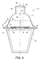
- FIGURE 4 is a side cross-sectional view taken along line 4-4 in FIGURE 7 (the translucent cover shown in FIGURE 4 is the same as FIGURE 2 as opposed to FIGURE 7 ).
- FIGURE 5 is a cross-sectional view shown in perspective taken along line 5-5 in FIGURE 7 .
- FIGURE 6 is a cross-sectional view shown in perspective taken along line 6-6 in FIGURE 7 .
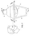
- FIGURE 7 is a side elevation view of the light fixture shown in FIGURE 1 showing an alternative embodiment of a translucent cover for the light engine.
- a decorative light fixture 10 includes a light engine 12 disposed within a housing where the housing includes a shroud 14 and a lower housing 16 connected to the shroud.
- the decorative light fixture 10 can mount to a post where the light fixture illuminates a pathway, a street or another area.
- the light fixture can have a similar look to decorative light fixtures that typically include a 75 watt metal-halide lamp.
- the light fixture can also be useful as a pendant light, where no pole is provided but instead the light fixture hangs from a bracket or other support.
- the light engine 12 includes a heat sink 20 and a light source in thermal communication with the heat sink.
- the light source is a plurality of LEDs 22 mounted on a printed circuit board (“PCB") 24 attached to a lower surface 26 of the heat sink 20.
- the light engine 12 also includes reflectors 28 that redirect light emanating from the LEDs 22.
- the reflectors 28 could be replaced by refractive optics to redirect light where it is desired.
- a translucent cover 32 attaches to the lower surface 26 of the heat sink 20 and defines a sealed cavity 34 ( FIGURE 4 ) in which the electrical components of the LED light engine are housed.
- brackets 36 are used to attach the translucent cover 32 to the lower surface 26 of the heat sink 20.
- the light engine 12 is more particularly described in International Application No. PCT/US2008/70184 , which is incorporated by reference in its entirety.
- LED light engines can require aggressive cooling to provide a bright long lasting light source. Where a decorative lighting fixture is desired, it can be difficult to allow for adequate air flow and adequate surface area of the heat sink to cool the LED light engine.
- By shaping an internal surface 38 of the shroud 14 to direct cool air over the heat sink 20 natural convection can be used to cool the LED light engine 14 without the need for a fan or heat pipe. Additionally, the heat does not need to be conducted into a pole upon which the light fixture can be mounted. This allows the light fixture to be used as a pendant light since no pole is required for a heat sink.
- the decorative shroud 14 covers the light engine 12 to define an air path, designated by arrow 40, between an air inlet 42 and an exhaust 44.
- the air inlet 42 is disposed vertically below the exhaust 44. Air moves between the air inlet and the exhaust via natural convection - fans to move the air and additional heat removal components, e.g. heat pipes, can be unnecessary.
- the air path is shaped to direct air over the heat sink 20 so that the air exits the shroud 14 above the light engine 12. Both the air inlet 42 and the exhaust 44 are in communication with ambient.
- the shroud also defines an internal volume 46 covering the heat sink 20.
- the shroud 14 defines a vertical axis 50, which is also a central axis of the light fixture 10.
- the shroud 14 tapers inwardly toward the vertical axis from a lower edge towards an upper end of the shroud. More particular to the embodiment that is illustrated, the shroud 14 tapers toward a cylindrical section 48 that is at the top of the shroud and concentric with the vertical central axis 50.
- the cross-sectional area of the internal volume 46 taken normal to the central axis 50 adjacent the inlet 42 (see FIGURE 5 ) and not occupied by the heat sink 20 is greater than the cross-sectional area of the internal volume taken normal to the central axis adjacent the outlet.
- cross sectional areas taken above the heat sink 20 can be less than the area of the inlet 44. This facilitates the shroud acting as a chimney to efficiently remove heat that is generated by the LEDs 22 ( FIGURE 3 ) from the light fixture.
- the heat sink 20 includes a base 52 and a plurality of spaced fins 54.
- the fins 54 extend upwardly from the base 52 into the internal volume 46 of the shroud 14 and are arranged to be in thermal communication with the air path such that air passing through the air inlet passes through spaces between adjacent fins prior to passing through the air exhaust 44.
- the fins 54 of the illustrated embodiment radiate from the central axis 50.
- the fins 54 are angularly spaced from one another around the central axis 50.
- the heat sink 20 also includes a central pillar 56 that is coaxial with the central axis 50 and that extends upwardly from and normal to the base 52.
- each fin 54 includes a contoured distal edge 58 and the inner surface 62 of the shroud 14 is contoured to generally follow the distal edges of the fins.
- the area of the air inlet 42 is shown which is defined by a peripheral edge 60 of the base 52 of the heat sink 20 and the internal surface 38 of the shroud 14. Much of the peripheral edge 60 of the base 52 of the heat sink 60 is offset from the internal surface 38 of the shroud.
- the heat sink 20 includes extensions 62 (four extensions in the illustrated embodiment) to provide an attachment location for attaching the heat sink to the shroud 14.
- FIGURE 5 depicts an isometric view of a cross section taken normal to the central axis 50 through the shroud 14 and the heat sink 20 at the vertical location of the air inlet 42.
- FIGURE 7 shows the location of the cross section of FIGURE 5 .
- the shroud 14 and the heat sink 20 define an envelope 64, which is the internal volume 46 of the shroud 14 above the lower surface 26 of the heat sink 20 less the volume occupied by the heat sink.
- the cross-sectional area of the envelope 64 normal to the central axis 50 at locations above the lower surface 26 of the heat sink 20 taken through the heat sink is at least about 90% and less than about 150% of the area of the air inlet 42.
- the cross-sectional area of the envelope normal to the central axis at locations above the lower surface of the heat sink and taken through the heat sink is at least about 100% and less than about 120% of the area of the air inlet 42. Even more desirably, the area of the exhaust 44 is about 20% to about 30% less than the area of the inlet 42.
- the area of the air inlet 42 is shown in FIGURE 5 .
- the area of the envelope 64 which can be considered as the spaces between adjacent fins 54, through the cross section shown in FIGURE 6 is at least about 90% of the area of the air inlet and preferably less than about 150% of the area of the air inlet. This promotes a chimney effect where the shroud 14 acts as a chimney.
- the volume of the envelope 64 between the base 52 of the heat sink 20 and an upper edge of each heat fin 54 is too small, this can restrict airflow and not allow the highest possible velocity of airflow through the fixture to cool the LEDs.
- the volume of the envelope between the base 52 of the heat sink 20 and an upper edge of each fin 54 is too large, the air velocity over the heat sink can decrease as compared to an optimally designed envelope volume.
- the exhaust 44 is depicted schematically.
- the exhaust 44 can be formed via openings 70 formed in the shroud 14.
- FIGURE 1 shows three possible locations for these openings 70. It can be desirable to locate the openings 70 in locations that are protected from rainfall. Nevertheless, since the electrical components of the light engine 12 are disposed in a sealed cavity 34 ( FIGURE 4 - an electrical cable, which is not shown, passes into the sealed cavity to provide energy) the exhaust openings 70 can be located in areas where the ingress of water is possible during a rain storm. It can be desirable to have the area of the exhaust 44, which would be the total surface area for the openings 70, to be at least about 70% of the area of the air inlet 42.
- the area of exhaust can also be less than about 80% of the area of the inlet. This promotes the chimney effect that is desirable to remove heat via convection. If the ratio of the exhaust area to the air inlet area is too large or too small, this could be detrimental to the chimney effect.
- FIGURE 1 simply depicts locations where the exhaust openings 70 can be located on the shroud. The number and the size of the exhaust openings will be dependent upon the area of the air inlet and the amount of power delivered to the light source of the light engine.
- the lower housing 16 connects to the shroud 14 and includes openings 80 that are shaped to receive associated glass panels, which are typically found in decorative light fixtures that include an incandescent light source, a metal halide light source, or a halogen light source.
- the openings 80 can receive translucent panels 82 (only one is shown in FIGURE 1 ) or can be left open to ambient such that air entering from ambient passes through the openings prior to entering the air inlet 42.
- holes 84 in the lower housing 16 allow for the ingress of air to cool the light engine 12.
- the holes 84 shown in FIGURE 1 are simply to show possible locations for such holes. The total surface area of these holes 84 is dependent upon the flow that is desired to cool the light engine. Moreover, it can be desirable to locate these holes 84 on generally horizontal surfaces that are covered by other components of the light fixture so that the openings are protected from rain and other elements.
- the LEDs which are not visible in FIGURE 7 , are hidden by the shroud 14 or the lower housing 16 when viewed from horizontal at an elevation about equal to an elevation of the LEDs.
- the LEDs are disposed vertically above at least one of a lowermost edge 90 of the shroud 14 or an uppermost edge 92 of the openings 80 in the lower housing 16. This obscures the point light sources from view of a person viewing the LED light fixture 10 looking downward or horizontally with respect to the light engine and the central axis 50. This obscures the point light sources and provides for a more attractive light fixture.
- the translucent cover 32 can be changed from its flat configuration shown in FIGURE 1 to a hemispherical configuration shown in FIGURE 7 , but it still may be desirable to locate the LEDs so that they are hidden from view.
Landscapes
- Engineering & Computer Science (AREA)
- General Engineering & Computer Science (AREA)
- Physics & Mathematics (AREA)
- Geometry (AREA)
- Arrangement Of Elements, Cooling, Sealing, Or The Like Of Lighting Devices (AREA)
- Non-Portable Lighting Devices Or Systems Thereof (AREA)
Abstract
Description
- Decorative light fixtures typically include an attractive housing with a light source that is typically a metal halide lamp or a halogen lamp or an incandescent lamp. These light fixtures work well, but can be improved by using a more efficient and longer lasting light source.
- Light emitting diodes (LEDs) can provide a bright, longer lasting light engine as compared to a metal halide lamp or a halogen lamp. LEDs, however, generate a great amount of heat that needs to be dissipated to provide a bright, long lasting light engine. Dissipating this heat can be difficult where it is desirable to use an attractive housing that is similar in configuration to the known decorative housings used with metal halide or halogen lamps.
- A known decorative light fixture that employs an LED light engine in a conventional attractive housing, i.e., one that would typically include a metal halide or halogen lamp, conducts heat generated by the LEDs either into a pole upon which the light fixture is mounted or maintains the heat within a glass enclosure that forms a part of the housing. Either situation limits the amount of power that can be delivered to the LEDs. This is due to the pole typically not being a very good heat conductor or that the heat maintained within the glass enclosure results in heat still being maintained in a volume that is adjacent the LEDs. Furthermore, where the heat is dissipated into the pole upon which the light fixture is mounted, the pole can get hot. Also, for light fixtures where no pole is provided, e.g. a pendent light fixture, there is no pole which can act as a heat sink.
- Another drawback with known attractive light fixtures that employ an LED light engine is that the LEDs are point light sources, which are visible when viewing the light fixture from horizontal. When these point light sources are visible, this can result in an unattractive look for the light fixture.
- A decorative light fixture that overcomes the aforementioned shortcomings includes a light engine and a shroud. The light engine includes a heat sink and a light source in thermal communication with the heat sink. The shroud covers the light engine to define an air path between an air inlet and an exhaust. The air inlet is disposed vertically below the exhaust. The air path is shaped to direct air over the heat sink and to exit the shroud above the light engine. The light source can be a plurality of LEDs.
- The air inlet and the exhaust can each be in communication with ambient. The area of the air inlet can be at least about 20% larger than the area of the exhaust. The area of the exhaust can be less than about 30% larger than the area of the air inlet. The shroud can define a central axis and a cross sectional area normal to the central axis of a volume surrounded by the shroud adjacent the air inlet can be greater than the cross-sectional area normal to the central axis of the volume adjacent the outlet.
- The heat sink can include a base and fins. The fins can extend upwardly from the base and radiate from the central axis. The heat sink can further include a central pillar coaxial with the central axis that extends upwardly from and normal to the base. Some fins can have internal edges that are contiguous with the pillar and some fins can have internal edges that are spaced from the pillar. The heat sink can also include fins where the cross-sectional area normal to the central axis of an envelope, which is the area surrounded by the shroud less the area occupied by the fins, is at least about 90% and less than about 150% of the area of the air inlet. The envelope may be the volume above the lower surface of the heat sink surrounded by the shroud less the volume occupied by the heat sink.
- The shroud can taper inwardly toward a vertical axis. The shroud can also define a vertical axis and the heat sink can include fins that radiate from the vertical axis. The fins can include a contoured distal edge and an inner surface of the shroud can be contoured to generally follow at least one distal edge of the fins.
- The fixture can further include a lower housing connected to the shroud. The lower housing can include openings shaped to receive associated glass panels. The openings can be in communication with the air inlet such that air from ambient entering the air inlet passes through the openings. The light fixture can further include translucent panels received in these openings. A lower most edge of the light engine can be disposed vertically above at least one of a lower most edge of the shroud or an uppermost edge of the openings in the lower housing.
- The fixture can also include a lower housing connected to the shroud where the light source is a plurality of LEDs. The LEDs can be hidden by the shroud or the lower housing when viewed from horizontal at an elevation equal to an elevation of the LEDs. The fixture can also include a translucent cover connected to the heat sink to define a sealed cavity. The light source can be disposed in the sealed cavity. Portions of a peripheral edge of the heat sink can also be spaced from an internal surface of the shroud.
- The light fixture may comprise a light engine including a heat sink and a light source in thermal communication with the heat sink; and a shroud defining an internal volume and covering the heat sink to define an air path through the internal volume between an air inlet and an air exhaust, the air inlet being disposed vertically below the air exhaust; wherein the heat sink comprises a plurality of spaced fins extending into the internal volume of the shroud and arranged to be in thermal communication with the air path such that air passing through the air inlet passes through spaces between adjacent fins prior to passing through the air exhaust.
-
FIGURE 1 is a perspective view of a decorative light fixture. -
FIGURE 2 is a perspective view of a light engine for the decorative light fixture ofFIGURE 1 . -
FIGURE 3 is a perspective view of the light engine shown inFIGURE 2 with a translucent cover and retaining members for the translucent cover removed. -
FIGURE 4 is a side cross-sectional view taken along line 4-4 inFIGURE 7 (the translucent cover shown inFIGURE 4 is the same asFIGURE 2 as opposed toFIGURE 7 ). -
FIGURE 5 is a cross-sectional view shown in perspective taken along line 5-5 inFIGURE 7 . -
FIGURE 6 is a cross-sectional view shown in perspective taken along line 6-6 inFIGURE 7 . -
FIGURE 7 is a side elevation view of the light fixture shown inFIGURE 1 showing an alternative embodiment of a translucent cover for the light engine. - With reference to
FIGURE 1 , adecorative light fixture 10 includes alight engine 12 disposed within a housing where the housing includes ashroud 14 and alower housing 16 connected to the shroud. Thedecorative light fixture 10 can mount to a post where the light fixture illuminates a pathway, a street or another area. In this instance, the light fixture can have a similar look to decorative light fixtures that typically include a 75 watt metal-halide lamp. The light fixture can also be useful as a pendant light, where no pole is provided but instead the light fixture hangs from a bracket or other support. - With reference to
FIGURES 2 and 3 , thelight engine 12 includes aheat sink 20 and a light source in thermal communication with the heat sink. In the depicted embodiment, the light source is a plurality ofLEDs 22 mounted on a printed circuit board ("PCB") 24 attached to alower surface 26 of theheat sink 20. Thelight engine 12 also includesreflectors 28 that redirect light emanating from theLEDs 22. Thereflectors 28 could be replaced by refractive optics to redirect light where it is desired. Atranslucent cover 32 attaches to thelower surface 26 of theheat sink 20 and defines a sealed cavity 34 (FIGURE 4 ) in which the electrical components of the LED light engine are housed. With reference back toFIGURE 2 ,brackets 36 are used to attach thetranslucent cover 32 to thelower surface 26 of theheat sink 20. Thelight engine 12 is more particularly described in International Application No.PCT/US2008/70184 , which is incorporated by reference in its entirety. - LED light engines can require aggressive cooling to provide a bright long lasting light source. Where a decorative lighting fixture is desired, it can be difficult to allow for adequate air flow and adequate surface area of the heat sink to cool the LED light engine. By shaping an
internal surface 38 of theshroud 14 to direct cool air over theheat sink 20, natural convection can be used to cool theLED light engine 14 without the need for a fan or heat pipe. Additionally, the heat does not need to be conducted into a pole upon which the light fixture can be mounted. This allows the light fixture to be used as a pendant light since no pole is required for a heat sink. - With reference to
FIGURE 4 , thedecorative shroud 14 covers thelight engine 12 to define an air path, designated byarrow 40, between anair inlet 42 and anexhaust 44. Theair inlet 42 is disposed vertically below theexhaust 44. Air moves between the air inlet and the exhaust via natural convection - fans to move the air and additional heat removal components, e.g. heat pipes, can be unnecessary. The air path is shaped to direct air over theheat sink 20 so that the air exits theshroud 14 above thelight engine 12. Both theair inlet 42 and theexhaust 44 are in communication with ambient. The shroud also defines aninternal volume 46 covering theheat sink 20. - The
shroud 14 defines avertical axis 50, which is also a central axis of thelight fixture 10. In the illustrated embodiment, theshroud 14 tapers inwardly toward the vertical axis from a lower edge towards an upper end of the shroud. More particular to the embodiment that is illustrated, theshroud 14 tapers toward acylindrical section 48 that is at the top of the shroud and concentric with the verticalcentral axis 50. The cross-sectional area of theinternal volume 46 taken normal to thecentral axis 50 adjacent the inlet 42 (seeFIGURE 5 ) and not occupied by theheat sink 20 is greater than the cross-sectional area of the internal volume taken normal to the central axis adjacent the outlet. Also, cross sectional areas taken above theheat sink 20 can be less than the area of theinlet 44. This facilitates the shroud acting as a chimney to efficiently remove heat that is generated by the LEDs 22 (FIGURE 3 ) from the light fixture. - With reference back to
FIGURES 2 and 3 , theheat sink 20 includes abase 52 and a plurality of spacedfins 54. With reference toFIGURES 4 and6 , thefins 54 extend upwardly from the base 52 into theinternal volume 46 of theshroud 14 and are arranged to be in thermal communication with the air path such that air passing through the air inlet passes through spaces between adjacent fins prior to passing through theair exhaust 44. Thefins 54 of the illustrated embodiment radiate from thecentral axis 50. Thefins 54 are angularly spaced from one another around thecentral axis 50. With reference toFIGURE 6 , theheat sink 20 also includes acentral pillar 56 that is coaxial with thecentral axis 50 and that extends upwardly from and normal to thebase 52. Some of thefins 54 have internal edges that are contiguous with thepillar 56 and some fins have internal edges that are radially spaced from the pillar.Many fins 54 are shown in the depicted embodiment; however, the number of fins and the surface area occupied by the fins can be dependent upon the amount of power that is to be delivered to theLEDs 22 to provide the desired light output from the light fixture. Moreover, theradial fins 54 should allow higher air velocities through the light fixture due to natural convection as compared to fins having other orientations, but the fins can be provided to have other orientations other than the radial configuration that is shown. With reference toFIGURE 4 , eachfin 54 includes a contoureddistal edge 58 and theinner surface 62 of theshroud 14 is contoured to generally follow the distal edges of the fins. - With reference to
FIGURE 5 , the area of theair inlet 42 is shown which is defined by aperipheral edge 60 of thebase 52 of theheat sink 20 and theinternal surface 38 of theshroud 14. Much of theperipheral edge 60 of thebase 52 of theheat sink 60 is offset from theinternal surface 38 of the shroud. Theheat sink 20 includes extensions 62 (four extensions in the illustrated embodiment) to provide an attachment location for attaching the heat sink to theshroud 14. -
FIGURE 5 depicts an isometric view of a cross section taken normal to thecentral axis 50 through theshroud 14 and theheat sink 20 at the vertical location of theair inlet 42.FIGURE 7 shows the location of the cross section ofFIGURE 5 . With reference toFIGURE 6 , theshroud 14 and theheat sink 20 define anenvelope 64, which is theinternal volume 46 of theshroud 14 above thelower surface 26 of theheat sink 20 less the volume occupied by the heat sink. The cross-sectional area of theenvelope 64 normal to thecentral axis 50 at locations above thelower surface 26 of theheat sink 20 taken through the heat sink is at least about 90% and less than about 150% of the area of theair inlet 42. More desirably, the cross-sectional area of the envelope normal to the central axis at locations above the lower surface of the heat sink and taken through the heat sink is at least about 100% and less than about 120% of the area of theair inlet 42. Even more desirably, the area of theexhaust 44 is about 20% to about 30% less than the area of theinlet 42. - For example, the area of the
air inlet 42 is shown inFIGURE 5 . With reference toFIGURE 6 , the area of theenvelope 64, which can be considered as the spaces betweenadjacent fins 54, through the cross section shown inFIGURE 6 is at least about 90% of the area of the air inlet and preferably less than about 150% of the area of the air inlet. This promotes a chimney effect where theshroud 14 acts as a chimney. Where the volume of theenvelope 64 between the base 52 of theheat sink 20 and an upper edge of eachheat fin 54 is too small, this can restrict airflow and not allow the highest possible velocity of airflow through the fixture to cool the LEDs. Where the volume of the envelope between the base 52 of theheat sink 20 and an upper edge of eachfin 54 is too large, the air velocity over the heat sink can decrease as compared to an optimally designed envelope volume. - With reference to
FIGURE 4 , theexhaust 44 is depicted schematically. With reference toFIGURE 1 , theexhaust 44 can be formed viaopenings 70 formed in theshroud 14.FIGURE 1 shows three possible locations for theseopenings 70. It can be desirable to locate theopenings 70 in locations that are protected from rainfall. Nevertheless, since the electrical components of thelight engine 12 are disposed in a sealed cavity 34 (FIGURE 4 - an electrical cable, which is not shown, passes into the sealed cavity to provide energy) theexhaust openings 70 can be located in areas where the ingress of water is possible during a rain storm. It can be desirable to have the area of theexhaust 44, which would be the total surface area for theopenings 70, to be at least about 70% of the area of theair inlet 42. The area of exhaust can also be less than about 80% of the area of the inlet. This promotes the chimney effect that is desirable to remove heat via convection. If the ratio of the exhaust area to the air inlet area is too large or too small, this could be detrimental to the chimney effect.FIGURE 1 simply depicts locations where theexhaust openings 70 can be located on the shroud. The number and the size of the exhaust openings will be dependent upon the area of the air inlet and the amount of power delivered to the light source of the light engine. - With reference back to
FIGURE 1 , thelower housing 16 connects to theshroud 14 and includesopenings 80 that are shaped to receive associated glass panels, which are typically found in decorative light fixtures that include an incandescent light source, a metal halide light source, or a halogen light source. This gives the decorativeLED light fixture 10 the same general look as conventional light fixtures. Theopenings 80 can receive translucent panels 82 (only one is shown inFIGURE 1 ) or can be left open to ambient such that air entering from ambient passes through the openings prior to entering theair inlet 42. For the embodiments that include translucent panels received in theopenings 80, holes 84 in thelower housing 16 allow for the ingress of air to cool thelight engine 12. Theholes 84 shown inFIGURE 1 are simply to show possible locations for such holes. The total surface area of theseholes 84 is dependent upon the flow that is desired to cool the light engine. Moreover, it can be desirable to locate theseholes 84 on generally horizontal surfaces that are covered by other components of the light fixture so that the openings are protected from rain and other elements. - With reference to
FIGURE 7 , the LEDs, which are not visible inFIGURE 7 , are hidden by theshroud 14 or thelower housing 16 when viewed from horizontal at an elevation about equal to an elevation of the LEDs. To accomplish this, the LEDs are disposed vertically above at least one of a lowermost edge 90 of theshroud 14 or anuppermost edge 92 of theopenings 80 in thelower housing 16. This obscures the point light sources from view of a person viewing theLED light fixture 10 looking downward or horizontally with respect to the light engine and thecentral axis 50. This obscures the point light sources and provides for a more attractive light fixture. If desired, thetranslucent cover 32 can be changed from its flat configuration shown inFIGURE 1 to a hemispherical configuration shown inFIGURE 7 , but it still may be desirable to locate the LEDs so that they are hidden from view. - A decorative light fixture has been described with reference to the particular embodiments. Modifications and alterations will occur to those skilled in the art upon reading and understanding the preceding detailed description. It is intended that the invention be construed as including all such modifications and alterations insofar as they come within the scope of the appended claims or the equivalents thereof.
Claims (15)
- A light fixture comprising:a light engine including a heat sink and a light source in thermal communication with the heat sink;a shroud covering the heat sink to define an air path between an air inlet and an exhaust, the air inlet being disposed vertically below the exhaust and the air path being shaped to direct air over the heat sink and to exit the shroud above the light engine.
- The fixture of claim 1, wherein the air inlet and the exhaust are each in communication with ambient.
- The fixture of claim 1 or 2, wherein the shroud defines a central axis, and the cross-sectional area normal to the central axis of a volume surrounded by the shroud adjacent the inlet is greater than the cross-sectional area normal to the central axis of the volume adjacent the outlet.
- The fixture of claim 3, wherein the heat sink includes a base and fins that extend upwardly from the base and radiate from the central axis.
- The fixture of claim 4, wherein the heat sink further comprises a central pillar coaxial with the central axis and extending upwardly from and normal to the base, some fins having internal edges being contiguous with the pillar and some fins having internal edges being spaced from the pillar.
- The fixture of claim 3, wherein the heat sink includes fins, the cross-sectional area of an envelope normal to the central axis and through the heat sink, being at least about 90% and less than about 150% of the area of the air inlet, wherein the envelope is the volume above the lower surface of the heat sink surrounded by the shroud less the volume occupied by the heat sink.
- The fixture of any of the preceding claims, wherein the area of the air inlet is at least about 20% larger than the area of the exhaust.
- The fixture of any of the preceding claims, wherein the area of the air inlet is less than about 30% larger than the area of the exhaust.
- The fixture of any of the preceding claims, wherein the shroud tapers inwardly toward a vertical axis.
- The fixture of any of the preceding claims, wherein the shroud defines a vertical axis and the heat sink includes fins that radiate from the vertical axis.
- The fixture of claim 10, wherein the fins include a contoured distal edge each contoured to generally follow an inner surface of the shroud.
- The fixture of any of the preceding claims, further comprising a lower housing connected to the shroud, the lower housing including openings shaped to receive associated glass panels.
- The fixture of any of the preceding claims, further comprising a lower housing connected to the shroud wherein the light source is a plurality of LEDs, and the LEDs are hidden by the shroud or the lower housing when viewed from horizontal at an elevation about equal to an elevation of the LEDs.
- The fixture of any of the preceding claims, wherein portions of a peripheral edge of the heat sink are spaced from an internal surface of the shroud.
- A light fixture comprising:a light engine including a heat sink and a light source in thermal communication with the heat sink; anda shroud defining an internal volume and covering the heat sink to define an air path through the internal volume between an air inlet and an air exhaust, the air inlet being disposed vertically below the air exhaust;wherein the heat sink comprises a plurality of spaced fins extending into the internal volume of the shroud and arranged to be in thermal communication with the air path such that air passing through the air inlet passes through spaces between adjacent fins prior to passing through the air exhaust.
Priority Applications (1)
| Application Number | Priority Date | Filing Date | Title |
|---|---|---|---|
| PL09171786T PL2169302T3 (en) | 2008-09-30 | 2009-09-30 | Decorative light fixture including cooling system |
Applications Claiming Priority (1)
| Application Number | Priority Date | Filing Date | Title |
|---|---|---|---|
| US12/242,100 US7914182B2 (en) | 2008-09-30 | 2008-09-30 | Decorative light fixture including cooling system |
Publications (2)
| Publication Number | Publication Date |
|---|---|
| EP2169302A1 true EP2169302A1 (en) | 2010-03-31 |
| EP2169302B1 EP2169302B1 (en) | 2014-12-31 |
Family
ID=41479389
Family Applications (1)
| Application Number | Title | Priority Date | Filing Date |
|---|---|---|---|
| EP09171786.8A Not-in-force EP2169302B1 (en) | 2008-09-30 | 2009-09-30 | Decorative light fixture including cooling system |
Country Status (6)
| Country | Link |
|---|---|
| US (1) | US7914182B2 (en) |
| EP (1) | EP2169302B1 (en) |
| CN (1) | CN101713504B (en) |
| ES (1) | ES2532730T3 (en) |
| PL (1) | PL2169302T3 (en) |
| PT (1) | PT2169302E (en) |
Cited By (4)
| Publication number | Priority date | Publication date | Assignee | Title |
|---|---|---|---|---|
| FR2996906A1 (en) * | 2012-10-16 | 2014-04-18 | Antoine Araman | EXTERIOR LIGHTING DEVICE |
| CN103874881A (en) * | 2010-04-07 | 2014-06-18 | 西特科照明有限公司 | Lamp housing |
| EP2746652A1 (en) * | 2012-11-30 | 2014-06-25 | Fivep S.p.a. | LED lighting device |
| WO2014202987A1 (en) * | 2013-06-19 | 2014-12-24 | Jcc Lighting Products Limited | Lantern type luminaire |
Families Citing this family (24)
| Publication number | Priority date | Publication date | Assignee | Title |
|---|---|---|---|---|
| US20100128483A1 (en) * | 2008-11-25 | 2010-05-27 | Cooper Technologies Company | Led luminaire |
| US8104929B2 (en) * | 2008-11-26 | 2012-01-31 | Spring City Electrical Manufacturing Company | Outdoor lighting fixture using LEDs |
| US8382347B2 (en) * | 2009-04-02 | 2013-02-26 | Abl Ip Holding Llc | Light fixture |
| US8430533B1 (en) * | 2010-02-12 | 2013-04-30 | Cooper Technologies Company | Devices and methods for replacing LED light sources for LED-based luminaires |
| TWI397650B (en) * | 2010-09-15 | 2013-06-01 | Sunonwealth Electr Mach Ind Co | Lamp |
| CN102454933A (en) * | 2011-05-20 | 2012-05-16 | 张波 | Decorating lamp |
| US8740421B2 (en) | 2011-06-14 | 2014-06-03 | Litelab Corp. | Luminaire with enhanced thermal dissipation characteristics |
| US8746929B2 (en) | 2011-10-14 | 2014-06-10 | GE Lighting Solutions, LLC | Device with combined features of lighting and air purification |
| US9157585B2 (en) | 2012-03-28 | 2015-10-13 | Milwaukee Electric Tool Corporation | Area light |
| US9091402B2 (en) | 2012-03-28 | 2015-07-28 | Milwaukee Electric Tool Corporation | Area light |
| US9228733B2 (en) | 2013-03-15 | 2016-01-05 | Kenall Manufacturing Company | LED light fixture having circumferentially mounted drivers adjacent external heat sinks |
| USD779694S1 (en) | 2013-08-27 | 2017-02-21 | Milwaukee Electric Tool Corporation | Portable light |
| CN104421876A (en) * | 2013-09-06 | 2015-03-18 | 深圳市海洋王照明工程有限公司 | Fixing assembly |
| US20160053982A1 (en) * | 2014-08-19 | 2016-02-25 | Spring City Mfg. Co. | Outdoor lighting fixture |
| EP3254016B1 (en) | 2015-02-04 | 2019-10-02 | Milwaukee Electric Tool Corporation | Light |
| US10378739B2 (en) | 2015-04-24 | 2019-08-13 | Milwaukee Electric Tool Corporation | Stand light |
| US10775032B2 (en) | 2015-07-01 | 2020-09-15 | Milwaukee Electric Tool Corporation | Area light |
| US10323831B2 (en) | 2015-11-13 | 2019-06-18 | Milwaukee Electric Tool Corporation | Utility mount light |
| USD816252S1 (en) | 2016-05-16 | 2018-04-24 | Milwaukee Electric Tool Corporation | Light |
| CN108361575A (en) * | 2018-01-31 | 2018-08-03 | 嘉兴爱劳科斯智能照明有限公司 | A kind of layer-stepping desk lamp |
| USD952231S1 (en) * | 2018-09-25 | 2022-05-17 | Signify Holding B.V. | Lighting fixture |
| USD923846S1 (en) * | 2020-09-23 | 2021-06-29 | Jianzi Peng | Solar post light |
| US11592165B1 (en) * | 2022-08-17 | 2023-02-28 | B.C. Lighting LLC | Modular light housing |
| CN222950943U (en) * | 2024-08-08 | 2025-06-06 | 东莞嘉盛照明科技有限公司 | Lighting device |
Citations (5)
| Publication number | Priority date | Publication date | Assignee | Title |
|---|---|---|---|---|
| US20020144809A1 (en) * | 2001-04-09 | 2002-10-10 | Siu Wing Ming | Laminated heat transfer device and method of producing thereof |
| WO2004088761A1 (en) * | 2003-04-02 | 2004-10-14 | Lucea Ag | Light-emitting panel |
| US20050146874A1 (en) * | 2004-01-02 | 2005-07-07 | Leonard Cech | Using organic light emitting diodes (OLEDs) in landscape lighting applications |
| US20070195527A1 (en) * | 2004-08-18 | 2007-08-23 | Remco Solid State Lighting Inc. | System and method for power control in a led luminaire |
| WO2008061082A1 (en) * | 2006-11-14 | 2008-05-22 | Cree Led Lighting Solutions, Inc. | Light engine assemblies |
Family Cites Families (7)
| Publication number | Priority date | Publication date | Assignee | Title |
|---|---|---|---|---|
| US7144135B2 (en) * | 2003-11-26 | 2006-12-05 | Philips Lumileds Lighting Company, Llc | LED lamp heat sink |
| JP2006310057A (en) * | 2005-04-27 | 2006-11-09 | Arumo Technos Kk | LED lighting and LED lighting control circuit |
| JP2007048638A (en) * | 2005-08-10 | 2007-02-22 | Pearl Denkyu Seisakusho:Kk | Lighting device |
| US7663229B2 (en) * | 2006-07-12 | 2010-02-16 | Hong Kong Applied Science And Technology Research Institute Co., Ltd. | Lighting device |
| US7738235B2 (en) * | 2006-07-31 | 2010-06-15 | B/E Aerospace, Inc. | LED light apparatus |
| US7686469B2 (en) * | 2006-09-30 | 2010-03-30 | Ruud Lighting, Inc. | LED lighting fixture |
| JP2008210593A (en) * | 2007-02-23 | 2008-09-11 | Matsushita Electric Works Ltd | Lighting device |
-
2008
- 2008-09-30 US US12/242,100 patent/US7914182B2/en not_active Expired - Fee Related
-
2009
- 2009-09-30 ES ES09171786.8T patent/ES2532730T3/en active Active
- 2009-09-30 CN CN200910179802.2A patent/CN101713504B/en not_active Expired - Fee Related
- 2009-09-30 PT PT09171786T patent/PT2169302E/en unknown
- 2009-09-30 PL PL09171786T patent/PL2169302T3/en unknown
- 2009-09-30 EP EP09171786.8A patent/EP2169302B1/en not_active Not-in-force
Patent Citations (5)
| Publication number | Priority date | Publication date | Assignee | Title |
|---|---|---|---|---|
| US20020144809A1 (en) * | 2001-04-09 | 2002-10-10 | Siu Wing Ming | Laminated heat transfer device and method of producing thereof |
| WO2004088761A1 (en) * | 2003-04-02 | 2004-10-14 | Lucea Ag | Light-emitting panel |
| US20050146874A1 (en) * | 2004-01-02 | 2005-07-07 | Leonard Cech | Using organic light emitting diodes (OLEDs) in landscape lighting applications |
| US20070195527A1 (en) * | 2004-08-18 | 2007-08-23 | Remco Solid State Lighting Inc. | System and method for power control in a led luminaire |
| WO2008061082A1 (en) * | 2006-11-14 | 2008-05-22 | Cree Led Lighting Solutions, Inc. | Light engine assemblies |
Cited By (5)
| Publication number | Priority date | Publication date | Assignee | Title |
|---|---|---|---|---|
| CN103874881A (en) * | 2010-04-07 | 2014-06-18 | 西特科照明有限公司 | Lamp housing |
| FR2996906A1 (en) * | 2012-10-16 | 2014-04-18 | Antoine Araman | EXTERIOR LIGHTING DEVICE |
| US9482422B2 (en) | 2012-10-16 | 2016-11-01 | Antoine ARAMAN | Outdoor lighting device |
| EP2746652A1 (en) * | 2012-11-30 | 2014-06-25 | Fivep S.p.a. | LED lighting device |
| WO2014202987A1 (en) * | 2013-06-19 | 2014-12-24 | Jcc Lighting Products Limited | Lantern type luminaire |
Also Published As
| Publication number | Publication date |
|---|---|
| US20100079998A1 (en) | 2010-04-01 |
| ES2532730T3 (en) | 2015-03-31 |
| EP2169302B1 (en) | 2014-12-31 |
| CN101713504B (en) | 2014-11-05 |
| PL2169302T3 (en) | 2015-06-30 |
| CN101713504A (en) | 2010-05-26 |
| US7914182B2 (en) | 2011-03-29 |
| PT2169302E (en) | 2015-03-26 |
Similar Documents
| Publication | Publication Date | Title |
|---|---|---|
| US7914182B2 (en) | Decorative light fixture including cooling system | |
| CN203082587U (en) | Lighting device with peripheral cooling channel | |
| US8272763B1 (en) | LED luminaire | |
| TWI394918B (en) | Lighting module and lighting system | |
| US8002446B1 (en) | Virtual direct and indirect suspended lighting fixture | |
| US8104929B2 (en) | Outdoor lighting fixture using LEDs | |
| CN202082661U (en) | Lighting device and lampshade with heat dissipation and light diffusion functions | |
| US20100061091A1 (en) | Led based acorn style luminaire | |
| EP1561993A3 (en) | LED lamps and method of cooling their LED | |
| US8419238B2 (en) | Lighting fixtures having enhanced heat sink performance | |
| CN103827580A (en) | LED luminaire | |
| KR20090042572A (en) | LED lamp | |
| CN103534527A (en) | Flat panel lighting device and retrofit kit | |
| TWM418237U (en) | Lighting device and light source module thereof | |
| MX2011007133A (en) | Lighting apparatus using light-emitting diode. | |
| CN106461165A (en) | Thermally dissipated lighting system | |
| JP3172223U (en) | light bulb | |
| JP2012164541A (en) | Straight-tube type led electric bulb | |
| US9523468B2 (en) | Lighting fixture having enhanced light distribution performance | |
| RU85784U1 (en) | LED LAMP | |
| KR100966582B1 (en) | Illuminator for lamp post thereby | |
| KR100778235B1 (en) | Fanless heat dissipation LED lighting fixtures | |
| TW201113467A (en) | Reduced size LED luminaire | |
| RU88769U1 (en) | LED STREET LIGHT | |
| CN214425910U (en) | a tree lamp |
Legal Events
| Date | Code | Title | Description |
|---|---|---|---|
| PUAI | Public reference made under article 153(3) epc to a published international application that has entered the european phase |
Free format text: ORIGINAL CODE: 0009012 |
|
| AK | Designated contracting states |
Kind code of ref document: A1 Designated state(s): AT BE BG CH CY CZ DE DK EE ES FI FR GB GR HR HU IE IS IT LI LT LU LV MC MK MT NL NO PL PT RO SE SI SK SM TR |
|
| AX | Request for extension of the european patent |
Extension state: AL BA RS |
|
| 17P | Request for examination filed |
Effective date: 20100922 |
|
| 17Q | First examination report despatched |
Effective date: 20101014 |
|
| RAP1 | Party data changed (applicant data changed or rights of an application transferred) |
Owner name: GE LIGHTING SOLUTIONS, LLC |
|
| RIC1 | Information provided on ipc code assigned before grant |
Ipc: F21V 29/00 20060101AFI20140527BHEP Ipc: F21Y 101/00 20060101ALN20140527BHEP Ipc: F21S 8/08 20060101ALI20140527BHEP |
|
| GRAP | Despatch of communication of intention to grant a patent |
Free format text: ORIGINAL CODE: EPIDOSNIGR1 |
|
| INTG | Intention to grant announced |
Effective date: 20140715 |
|
| GRAS | Grant fee paid |
Free format text: ORIGINAL CODE: EPIDOSNIGR3 |
|
| GRAA | (expected) grant |
Free format text: ORIGINAL CODE: 0009210 |
|
| AK | Designated contracting states |
Kind code of ref document: B1 Designated state(s): AT BE BG CH CY CZ DE DK EE ES FI FR GB GR HR HU IE IS IT LI LT LU LV MC MK MT NL NO PL PT RO SE SI SK SM TR |
|
| REG | Reference to a national code |
Ref country code: CH Ref legal event code: EP Ref country code: GB Ref legal event code: FG4D |
|
| REG | Reference to a national code |
Ref country code: IE Ref legal event code: FG4D |
|
| REG | Reference to a national code |
Ref country code: AT Ref legal event code: REF Ref document number: 704643 Country of ref document: AT Kind code of ref document: T Effective date: 20150215 |
|
| REG | Reference to a national code |
Ref country code: DE Ref legal event code: R096 Ref document number: 602009028655 Country of ref document: DE Effective date: 20150219 |
|
| REG | Reference to a national code |
Ref country code: PT Ref legal event code: SC4A Free format text: AVAILABILITY OF NATIONAL TRANSLATION Effective date: 20150313 |
|
| REG | Reference to a national code |
Ref country code: ES Ref legal event code: FG2A Ref document number: 2532730 Country of ref document: ES Kind code of ref document: T3 Effective date: 20150331 |
|
| PG25 | Lapsed in a contracting state [announced via postgrant information from national office to epo] |
Ref country code: NO Free format text: LAPSE BECAUSE OF FAILURE TO SUBMIT A TRANSLATION OF THE DESCRIPTION OR TO PAY THE FEE WITHIN THE PRESCRIBED TIME-LIMIT Effective date: 20150331 Ref country code: LT Free format text: LAPSE BECAUSE OF FAILURE TO SUBMIT A TRANSLATION OF THE DESCRIPTION OR TO PAY THE FEE WITHIN THE PRESCRIBED TIME-LIMIT Effective date: 20141231 Ref country code: FI Free format text: LAPSE BECAUSE OF FAILURE TO SUBMIT A TRANSLATION OF THE DESCRIPTION OR TO PAY THE FEE WITHIN THE PRESCRIBED TIME-LIMIT Effective date: 20141231 |
|
| REG | Reference to a national code |
Ref country code: NL Ref legal event code: VDEP Effective date: 20141231 |
|
| REG | Reference to a national code |
Ref country code: LT Ref legal event code: MG4D |
|
| PG25 | Lapsed in a contracting state [announced via postgrant information from national office to epo] |
Ref country code: LV Free format text: LAPSE BECAUSE OF FAILURE TO SUBMIT A TRANSLATION OF THE DESCRIPTION OR TO PAY THE FEE WITHIN THE PRESCRIBED TIME-LIMIT Effective date: 20141231 Ref country code: GR Free format text: LAPSE BECAUSE OF FAILURE TO SUBMIT A TRANSLATION OF THE DESCRIPTION OR TO PAY THE FEE WITHIN THE PRESCRIBED TIME-LIMIT Effective date: 20150401 Ref country code: HR Free format text: LAPSE BECAUSE OF FAILURE TO SUBMIT A TRANSLATION OF THE DESCRIPTION OR TO PAY THE FEE WITHIN THE PRESCRIBED TIME-LIMIT Effective date: 20141231 Ref country code: SE Free format text: LAPSE BECAUSE OF FAILURE TO SUBMIT A TRANSLATION OF THE DESCRIPTION OR TO PAY THE FEE WITHIN THE PRESCRIBED TIME-LIMIT Effective date: 20141231 |
|
| PG25 | Lapsed in a contracting state [announced via postgrant information from national office to epo] |
Ref country code: NL Free format text: LAPSE BECAUSE OF FAILURE TO SUBMIT A TRANSLATION OF THE DESCRIPTION OR TO PAY THE FEE WITHIN THE PRESCRIBED TIME-LIMIT Effective date: 20141231 |
|
| REG | Reference to a national code |
Ref country code: PL Ref legal event code: T3 |
|
| REG | Reference to a national code |
Ref country code: HU Ref legal event code: AG4A Ref document number: E023477 Country of ref document: HU |
|
| PG25 | Lapsed in a contracting state [announced via postgrant information from national office to epo] |
Ref country code: SK Free format text: LAPSE BECAUSE OF FAILURE TO SUBMIT A TRANSLATION OF THE DESCRIPTION OR TO PAY THE FEE WITHIN THE PRESCRIBED TIME-LIMIT Effective date: 20141231 Ref country code: RO Free format text: LAPSE BECAUSE OF FAILURE TO SUBMIT A TRANSLATION OF THE DESCRIPTION OR TO PAY THE FEE WITHIN THE PRESCRIBED TIME-LIMIT Effective date: 20141231 Ref country code: CZ Free format text: LAPSE BECAUSE OF FAILURE TO SUBMIT A TRANSLATION OF THE DESCRIPTION OR TO PAY THE FEE WITHIN THE PRESCRIBED TIME-LIMIT Effective date: 20141231 |
|
| PG25 | Lapsed in a contracting state [announced via postgrant information from national office to epo] |
Ref country code: IS Free format text: LAPSE BECAUSE OF FAILURE TO SUBMIT A TRANSLATION OF THE DESCRIPTION OR TO PAY THE FEE WITHIN THE PRESCRIBED TIME-LIMIT Effective date: 20150430 |
|
| REG | Reference to a national code |
Ref country code: DE Ref legal event code: R097 Ref document number: 602009028655 Country of ref document: DE |
|
| PG25 | Lapsed in a contracting state [announced via postgrant information from national office to epo] |
Ref country code: DK Free format text: LAPSE BECAUSE OF FAILURE TO SUBMIT A TRANSLATION OF THE DESCRIPTION OR TO PAY THE FEE WITHIN THE PRESCRIBED TIME-LIMIT Effective date: 20141231 Ref country code: EE Free format text: LAPSE BECAUSE OF FAILURE TO SUBMIT A TRANSLATION OF THE DESCRIPTION OR TO PAY THE FEE WITHIN THE PRESCRIBED TIME-LIMIT Effective date: 20141231 |
|
| PLBE | No opposition filed within time limit |
Free format text: ORIGINAL CODE: 0009261 |
|
| STAA | Information on the status of an ep patent application or granted ep patent |
Free format text: STATUS: NO OPPOSITION FILED WITHIN TIME LIMIT |
|
| 26N | No opposition filed |
Effective date: 20151001 |
|
| REG | Reference to a national code |
Ref country code: AT Ref legal event code: UEP Ref document number: 704643 Country of ref document: AT Kind code of ref document: T Effective date: 20141231 |
|
| PG25 | Lapsed in a contracting state [announced via postgrant information from national office to epo] |
Ref country code: SI Free format text: LAPSE BECAUSE OF FAILURE TO SUBMIT A TRANSLATION OF THE DESCRIPTION OR TO PAY THE FEE WITHIN THE PRESCRIBED TIME-LIMIT Effective date: 20141231 |
|
| PG25 | Lapsed in a contracting state [announced via postgrant information from national office to epo] |
Ref country code: LU Free format text: LAPSE BECAUSE OF FAILURE TO SUBMIT A TRANSLATION OF THE DESCRIPTION OR TO PAY THE FEE WITHIN THE PRESCRIBED TIME-LIMIT Effective date: 20150930 Ref country code: MC Free format text: LAPSE BECAUSE OF FAILURE TO SUBMIT A TRANSLATION OF THE DESCRIPTION OR TO PAY THE FEE WITHIN THE PRESCRIBED TIME-LIMIT Effective date: 20141231 |
|
| REG | Reference to a national code |
Ref country code: FR Ref legal event code: PLFP Year of fee payment: 8 |
|
| PG25 | Lapsed in a contracting state [announced via postgrant information from national office to epo] |
Ref country code: MT Free format text: LAPSE BECAUSE OF FAILURE TO SUBMIT A TRANSLATION OF THE DESCRIPTION OR TO PAY THE FEE WITHIN THE PRESCRIBED TIME-LIMIT Effective date: 20141231 |
|
| PG25 | Lapsed in a contracting state [announced via postgrant information from national office to epo] |
Ref country code: SM Free format text: LAPSE BECAUSE OF FAILURE TO SUBMIT A TRANSLATION OF THE DESCRIPTION OR TO PAY THE FEE WITHIN THE PRESCRIBED TIME-LIMIT Effective date: 20141231 Ref country code: BG Free format text: LAPSE BECAUSE OF FAILURE TO SUBMIT A TRANSLATION OF THE DESCRIPTION OR TO PAY THE FEE WITHIN THE PRESCRIBED TIME-LIMIT Effective date: 20141231 |
|
| PG25 | Lapsed in a contracting state [announced via postgrant information from national office to epo] |
Ref country code: CY Free format text: LAPSE BECAUSE OF FAILURE TO SUBMIT A TRANSLATION OF THE DESCRIPTION OR TO PAY THE FEE WITHIN THE PRESCRIBED TIME-LIMIT Effective date: 20141231 |
|
| PG25 | Lapsed in a contracting state [announced via postgrant information from national office to epo] |
Ref country code: TR Free format text: LAPSE BECAUSE OF FAILURE TO SUBMIT A TRANSLATION OF THE DESCRIPTION OR TO PAY THE FEE WITHIN THE PRESCRIBED TIME-LIMIT Effective date: 20141231 |
|
| REG | Reference to a national code |
Ref country code: FR Ref legal event code: PLFP Year of fee payment: 9 |
|
| PGFP | Annual fee paid to national office [announced via postgrant information from national office to epo] |
Ref country code: IT Payment date: 20170925 Year of fee payment: 9 Ref country code: FR Payment date: 20170925 Year of fee payment: 9 Ref country code: CH Payment date: 20170927 Year of fee payment: 9 Ref country code: GB Payment date: 20170927 Year of fee payment: 9 |
|
| PGFP | Annual fee paid to national office [announced via postgrant information from national office to epo] |
Ref country code: IE Payment date: 20170928 Year of fee payment: 9 Ref country code: HU Payment date: 20170911 Year of fee payment: 9 Ref country code: BE Payment date: 20170927 Year of fee payment: 9 Ref country code: PT Payment date: 20170831 Year of fee payment: 9 Ref country code: PL Payment date: 20170918 Year of fee payment: 9 Ref country code: AT Payment date: 20170901 Year of fee payment: 9 |
|
| PGFP | Annual fee paid to national office [announced via postgrant information from national office to epo] |
Ref country code: DE Payment date: 20170927 Year of fee payment: 9 |
|
| PGFP | Annual fee paid to national office [announced via postgrant information from national office to epo] |
Ref country code: ES Payment date: 20171002 Year of fee payment: 9 |
|
| PG25 | Lapsed in a contracting state [announced via postgrant information from national office to epo] |
Ref country code: MK Free format text: LAPSE BECAUSE OF FAILURE TO SUBMIT A TRANSLATION OF THE DESCRIPTION OR TO PAY THE FEE WITHIN THE PRESCRIBED TIME-LIMIT Effective date: 20141231 |
|
| REG | Reference to a national code |
Ref country code: DE Ref legal event code: R119 Ref document number: 602009028655 Country of ref document: DE |
|
| REG | Reference to a national code |
Ref country code: CH Ref legal event code: PL |
|
| REG | Reference to a national code |
Ref country code: AT Ref legal event code: MM01 Ref document number: 704643 Country of ref document: AT Kind code of ref document: T Effective date: 20180930 |
|
| GBPC | Gb: european patent ceased through non-payment of renewal fee |
Effective date: 20180930 |
|
| REG | Reference to a national code |
Ref country code: BE Ref legal event code: FP Effective date: 20150311 Ref country code: BE Ref legal event code: MM Effective date: 20180930 |
|
| REG | Reference to a national code |
Ref country code: IE Ref legal event code: MM4A |
|
| PG25 | Lapsed in a contracting state [announced via postgrant information from national office to epo] |
Ref country code: PT Free format text: LAPSE BECAUSE OF NON-PAYMENT OF DUE FEES Effective date: 20190401 Ref country code: IT Free format text: LAPSE BECAUSE OF NON-PAYMENT OF DUE FEES Effective date: 20180930 Ref country code: DE Free format text: LAPSE BECAUSE OF NON-PAYMENT OF DUE FEES Effective date: 20190402 Ref country code: IE Free format text: LAPSE BECAUSE OF NON-PAYMENT OF DUE FEES Effective date: 20180930 |
|
| PG25 | Lapsed in a contracting state [announced via postgrant information from national office to epo] |
Ref country code: BE Free format text: LAPSE BECAUSE OF NON-PAYMENT OF DUE FEES Effective date: 20180930 Ref country code: FR Free format text: LAPSE BECAUSE OF NON-PAYMENT OF DUE FEES Effective date: 20180930 Ref country code: HU Free format text: LAPSE BECAUSE OF NON-PAYMENT OF DUE FEES Effective date: 20181001 Ref country code: LI Free format text: LAPSE BECAUSE OF NON-PAYMENT OF DUE FEES Effective date: 20180930 Ref country code: CH Free format text: LAPSE BECAUSE OF NON-PAYMENT OF DUE FEES Effective date: 20180930 |
|
| PG25 | Lapsed in a contracting state [announced via postgrant information from national office to epo] |
Ref country code: GB Free format text: LAPSE BECAUSE OF NON-PAYMENT OF DUE FEES Effective date: 20180930 Ref country code: AT Free format text: LAPSE BECAUSE OF NON-PAYMENT OF DUE FEES Effective date: 20180930 |
|
| REG | Reference to a national code |
Ref country code: ES Ref legal event code: FD2A Effective date: 20191104 |
|
| PG25 | Lapsed in a contracting state [announced via postgrant information from national office to epo] |
Ref country code: ES Free format text: LAPSE BECAUSE OF NON-PAYMENT OF DUE FEES Effective date: 20181001 |
|
| PG25 | Lapsed in a contracting state [announced via postgrant information from national office to epo] |
Ref country code: PL Free format text: LAPSE BECAUSE OF NON-PAYMENT OF DUE FEES Effective date: 20180930 |