EP2169182A2 - Integrated guide vane assembly - Google Patents
Integrated guide vane assembly Download PDFInfo
- Publication number
- EP2169182A2 EP2169182A2 EP09171243A EP09171243A EP2169182A2 EP 2169182 A2 EP2169182 A2 EP 2169182A2 EP 09171243 A EP09171243 A EP 09171243A EP 09171243 A EP09171243 A EP 09171243A EP 2169182 A2 EP2169182 A2 EP 2169182A2
- Authority
- EP
- European Patent Office
- Prior art keywords
- guide vane
- bifurcation
- assembly
- leading edge
- rotation
- Prior art date
- Legal status (The legal status is an assumption and is not a legal conclusion. Google has not performed a legal analysis and makes no representation as to the accuracy of the status listed.)
- Withdrawn
Links
Images


Classifications
-
- F—MECHANICAL ENGINEERING; LIGHTING; HEATING; WEAPONS; BLASTING
- F01—MACHINES OR ENGINES IN GENERAL; ENGINE PLANTS IN GENERAL; STEAM ENGINES
- F01D—NON-POSITIVE DISPLACEMENT MACHINES OR ENGINES, e.g. STEAM TURBINES
- F01D9/00—Stators
- F01D9/02—Nozzles; Nozzle boxes; Stator blades; Guide conduits, e.g. individual nozzles
- F01D9/04—Nozzles; Nozzle boxes; Stator blades; Guide conduits, e.g. individual nozzles forming ring or sector
- F01D9/041—Nozzles; Nozzle boxes; Stator blades; Guide conduits, e.g. individual nozzles forming ring or sector using blades
-
- F—MECHANICAL ENGINEERING; LIGHTING; HEATING; WEAPONS; BLASTING
- F01—MACHINES OR ENGINES IN GENERAL; ENGINE PLANTS IN GENERAL; STEAM ENGINES
- F01D—NON-POSITIVE DISPLACEMENT MACHINES OR ENGINES, e.g. STEAM TURBINES
- F01D25/00—Component parts, details, or accessories, not provided for in, or of interest apart from, other groups
- F01D25/16—Arrangement of bearings; Supporting or mounting bearings in casings
- F01D25/162—Bearing supports
-
- F—MECHANICAL ENGINEERING; LIGHTING; HEATING; WEAPONS; BLASTING
- F05—INDEXING SCHEMES RELATING TO ENGINES OR PUMPS IN VARIOUS SUBCLASSES OF CLASSES F01-F04
- F05D—INDEXING SCHEME FOR ASPECTS RELATING TO NON-POSITIVE-DISPLACEMENT MACHINES OR ENGINES, GAS-TURBINES OR JET-PROPULSION PLANTS
- F05D2250/00—Geometry
- F05D2250/30—Arrangement of components
- F05D2250/31—Arrangement of components according to the direction of their main axis or their axis of rotation
- F05D2250/314—Arrangement of components according to the direction of their main axis or their axis of rotation the axes being inclined in relation to each other
-
- Y—GENERAL TAGGING OF NEW TECHNOLOGICAL DEVELOPMENTS; GENERAL TAGGING OF CROSS-SECTIONAL TECHNOLOGIES SPANNING OVER SEVERAL SECTIONS OF THE IPC; TECHNICAL SUBJECTS COVERED BY FORMER USPC CROSS-REFERENCE ART COLLECTIONS [XRACs] AND DIGESTS
- Y02—TECHNOLOGIES OR APPLICATIONS FOR MITIGATION OR ADAPTATION AGAINST CLIMATE CHANGE
- Y02T—CLIMATE CHANGE MITIGATION TECHNOLOGIES RELATED TO TRANSPORTATION
- Y02T50/00—Aeronautics or air transport
- Y02T50/60—Efficient propulsion technologies, e.g. for aircraft
Definitions
- the technology described herein relates generally to turbomachinery, particularly to gas turbine engines, and more particularly, to a gas turbine engine guide vane assembly.
- At least one known gas turbine engine assembly includes a fan assembly that is mounted upstream from a core gas turbine engine. During operation, a portion of the airflow discharged from the fan assembly is channeled downstream to the core gas turbine engine wherein the airflow is further compressed. The compressed airflow is then channeled into a combustor, mixed with fuel, and ignited to generate hot combustion gases. The combustion gases are then channeled to a turbine, which extracts energy from the combustion gases for powering the compressor, as well as producing useful work to propel an aircraft in flight. The other portion of the airflow discharged from the fan assembly exits the engine through a fan stream nozzle.
- At least one known gas turbine engine assembly includes an outlet guide vane assembly that is used to remove swirl before the fan nozzle.
- Such an outlet guide vane assembly is configured to turn the airflow discharged from the fan assembly to a substantially axial direction prior to the fan flow being exhausted from the bypass duct.
- the outlet guide vane assembly also provides structural stiffness to the fan frame. More specifically, outlet guide vane assemblies generally include a plurality of outlet guide vanes that are coupled to the fan frame.
- fan frame assemblies include one or more (frequently two, diametrically opposed) dividing structures, often called “bifurcations", which divide the annular space defined by the bypass duct into two semi-annular spaces.
- These dividing structures are typically hollow duct-like structures through which various mechanical, electrical, pneumatic, hydraulic, or other connections (including structural supports) can pass without causing disruption to the airflow through the bypass duct.
- the bifurcations "fair” or guide the flow in aerodynamic fashion around these structures, and may be integrated or blended into the profile of an upstream guide vane to reduce the number of individual airflow disruptions.
- Geometric sweep and lean characteristics for guide vanes have been previously demonstrated to be useful design parameters for reducing noise caused by aerodynamic interactions between guide vanes and upstream and/or downstream rotating elements such as fan blades.
- bifurcations are typically radially oriented there remains a need for an improved approach to integrating advanced design swept and/or leaned guide vanes with bypass duct bifurcations.
- an integrated outlet guide vane assembly for turbomachinery typically includes at least one outlet guide vane and at least one bifurcation having a leading edge and a trailing edge.
- the turbomachinery has a central axis of rotation and a defined direction of rotation about the axis.
- the guide vane comprises an airfoil having a leading edge and a trailing edge and has a non-zero angle of lean in the direction of rotation and a non-zero sweep angle relative to a line perpendicular to the central axis.
- the leading edge of the bifurcation has a non-zero angle of lean in the direction of rotation and a non-zero sweep angle relative to a line perpendicular to the central axis.
- the trailing edge of the vane is faired into the leading edge of the bifurcation.
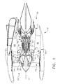
- FIG. 1 is a cross-sectional schematic illustration of an exemplary gas turbine engine assembly 10 having a longitudinal axis 11.
- Gas turbine engine assembly 10 includes a fan assembly 12 and a core gas turbine engine 13.
- Core gas turbine engine 13 includes a high pressure compressor 14, a combustor 16, and a high pressure turbine 18.
- gas turbine engine assembly 10 also includes a low pressure turbine 20, and a multi-stage booster compressor 22, and a splitter 44 that substantially circumscribes booster 22.
- Fan assembly 12 includes an array of fan blades 24 extending radially outward from a rotor disk 26.
- Gas turbine engine assembly 10 has an intake side 28 and an exhaust side 30.
- Fan assembly 12, booster 22, and turbine 20 are coupled together by a first rotor shaft 31, and compressor 14 and turbine 18 are coupled together by a second rotor shaft 32.
- the compressed air that is discharged from booster 22 is channeled through compressor 14 wherein the airflow is further compressed and delivered to combustor 16.
- Hot products of combustion (not shown in Figure 1 ) from combustor 16 are utilized to drive turbines 18 and 20, and turbine 20 is utilized to drive fan assembly 12 and booster 22 by way of shaft 31.
- Gas turbine engine assembly 10 is operable at a range of operating conditions between design operating conditions and off-design operating conditions.
- a second portion 52 of the airflow discharged from fan assembly 12 is channeled through a bypass duct 40 to bypass a portion of the airflow from fan assembly 12 around the core gas turbine engine 13. More specifically, bypass duct 40 extends between a fan casing or shroud 42 and splitter 44. Accordingly, a first portion 50 of the airflow from fan assembly 12 is channeled through booster 22 and then into compressor 14 as described above, and a second portion 52 of the airflow from fan assembly 12 is channeled through bypass duct 40 to provide thrust for an aircraft, for example.
- Gas turbine engine assembly 10 also includes a fan frame assembly 60 to provide structural support for fan assembly 12 and is also utilized to couple fan assembly 12 to core gas turbine engine 13.
- Fan frame assembly 60 includes a plurality of outlet guide vanes 70 that typically extend substantially radially, between a radially-outer mounting flange and a radially-inner mounting flange, and are circumferentially-spaced within bypass duct 40.
- Fan frame assembly 60 may also include a plurality of struts that are coupled between a radially outer mounting flange and a radially inner mounting flange.
- fan frame assembly 60 is fabricated in arcuate segments in which flanges are coupled to outlet guide vanes 70 and struts.
- outlet guide vanes and struts are coupled coaxially within bypass duct 40.
- outlet guide vanes 70 may be coupled upstream or downstream from struts within bypass duct 40. Guide vanes 70 serve to turn the airflow downstream from rotating blades such as fan blades 24.
- Fan frame assembly 60 is one of various frame and support assemblies of gas turbine engine assembly 10 that are used to facilitate maintaining an orientation of various components within gas turbine engine assembly 10. More specifically, such frame and support assemblies interconnect stationary components and provide rotor bearing supports. Fan frame assembly 60 is coupled downstream from fan assembly 12 within bypass duct 40 such that outlet guide vanes 70 and struts are circumferentially-spaced around the outlet of fan assembly 12 and extend across the airflow path discharged from fan assembly 12.
- Figure 1 also illustrates the bifurcations 80 and 82 which extend radially through the bypass duct 40 between the fan casing or shroud 42 and splitter 44.
- the configuration of bifurcations 80 and 82 will be described in greater detail hereafter. While the figures herein illustrate two (upper and lower) bifurcations, it is possible that for certain configurations (including certain engine mounting arrangements) that either a single bifurcation or three or more bifurcations may be utilized.
- Figure 2 is an enlarged elevational cross-sectional view of the gas turbine engine 10 of Figure 1 , showing the elements of Figure 1 in greater detail as well as illustrating the location at which the sectional elevational view of Figure 3 is taken along lines 3-3.
- Figure 3 is an elevational view which illustrates, looking rearward from the front of the gas turbine engine, the relationship of the vanes 70 to the reference lines and axes of the gas turbine engine 10.
- the guide vanes 70 are circumferentially distributed around the central axis 11 of the gas turbine engine 10.
- Figure 3 illustrates the direction of rotation D of the gas turbine engine during normal operation, the radial direction R, and the lean angle L which leaned typical guide vanes 70 make with respect to the radial direction R.
- the lean angle L shown in the direction of fan rotation, which provides maximum acoustic benefit.
- Figure 4 is a plan view looking downward on elements of the gas turbine engine 10 to illustrate the relationship between the fan assembly 12, guide vanes 70, and bifurcation 80.
- the guide vanes 70 incorporate lean in the direction of rotation, and a sweep angle toward the rear of the engine from their inner end (root) 72 to their outer end (tip) 74.
- the bifurcation 80 is a hollow duct-like structure through which various mechanical, electrical, pneumatic, hydraulic, or other connections (including structural supports) can pass without causing disruption to the airflow through the bypass duct 40.
- the upper bifurcation houses the engine mounts and various electrical, hydraulic, and pneumatic systems while the lower bifurcation houses oil drains and the like.
- the bifurcations "fair" or guide the flow in aerodynamic fashion around these structures.
- the forward edge of the bifurcation 80 is leaned and/or swept to meet with and blend into the trailing edge 73 of the guide vane 70.
- the remaining portion of the bifurcation, aft of the leading edge portion may be similarly leaned or may be more radially oriented as needed to accommodate structural loads and the passage of the various service connections.
- Figure 5 shows the aerodynamic integration of the guide vane 70, and particularly the trailing edge of the guide vane 70, into the leading edge of the bifurcation 80. This is an important aspect of implementing the swept and leaned guide vane designs into the integral vane frame engine architecture.
- Lean and/or sweep of the guide vanes and bifurcations may provide aerodynamic, acoustic, and/or other benefits in terms of gas turbine engine performance.
- Angles of sweep S such as about 0 to about 40 degrees aft, relative to the hub radial direction (normal to the central axis), and/or circumferentially leaning the outlet guide vane 70 with lean angles L from about -40 to about 0 degrees, relative to the radial orientation, in the direction of fan rotation, may provide acoustic benefits, such as reductions in noise from the fan assembly 12.
- Angles of sweep greater than about 5 degrees aft, and angles of lean greater than about -5 degrees, are believed to be particularly useful.
- Negative angles of sweep i.e., forward sweep
- Positive lean angles are also possible, in comparable angular ranges of about 0 to about 40 degrees.
- the drawing figures depict configurations employing a lean angle of about -10 degrees and a sweep angle of about 25 degrees.
- Figure 8 is an elevational partial cross-sectional view similar to Figure 2 of another embodiment of the gas turbine engine assembly shown in Figure 1 .
- the same numbering scheme for individual elements described above with respect to Figure 2 is employed.
- the configuration of Figure 8 differs from that of Figure 2 in that the fan frame assembly 60 includes guide vanes 70 along with a smaller number (such as, for example, 6) structural strut members 90 spaced annularly around the bypass duct and a bifurcation 80.
- the strut members 90 are load-bearing elements which reduce the structural loads imparted to the guide vanes 70.
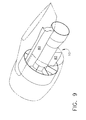
- FIG. 9 is a perspective view of the gas turbine engine of Figure 8 in a typical installation configuration for an aircraft (not shown).
- the guide vanes and bifurcations may be fabricated from any suitable materials using any suitable fabrication methods as are known in the art and suitable for the intended configuration and operating environment. Configuration details, such as the number and thickness of guide vanes 70, may influence the degree to which lean and sweep can be implemented without interfering with adjacent vanes.
Landscapes
- Engineering & Computer Science (AREA)
- Mechanical Engineering (AREA)
- General Engineering & Computer Science (AREA)
- Structures Of Non-Positive Displacement Pumps (AREA)
- Turbine Rotor Nozzle Sealing (AREA)
Abstract
Description
- The technology described herein relates generally to turbomachinery, particularly to gas turbine engines, and more particularly, to a gas turbine engine guide vane assembly.
- At least one known gas turbine engine assembly includes a fan assembly that is mounted upstream from a core gas turbine engine. During operation, a portion of the airflow discharged from the fan assembly is channeled downstream to the core gas turbine engine wherein the airflow is further compressed. The compressed airflow is then channeled into a combustor, mixed with fuel, and ignited to generate hot combustion gases. The combustion gases are then channeled to a turbine, which extracts energy from the combustion gases for powering the compressor, as well as producing useful work to propel an aircraft in flight. The other portion of the airflow discharged from the fan assembly exits the engine through a fan stream nozzle.
- To facilitate channeling the airflow from the fan assembly to the fan stream exhaust, at least one known gas turbine engine assembly includes an outlet guide vane assembly that is used to remove swirl before the fan nozzle. Such an outlet guide vane assembly is configured to turn the airflow discharged from the fan assembly to a substantially axial direction prior to the fan flow being exhausted from the bypass duct. In addition to turning the fan airflow, the outlet guide vane assembly also provides structural stiffness to the fan frame. More specifically, outlet guide vane assemblies generally include a plurality of outlet guide vanes that are coupled to the fan frame.
- In addition to outlet guide vanes, many fan frame assemblies include one or more (frequently two, diametrically opposed) dividing structures, often called "bifurcations", which divide the annular space defined by the bypass duct into two semi-annular spaces. These dividing structures are typically hollow duct-like structures through which various mechanical, electrical, pneumatic, hydraulic, or other connections (including structural supports) can pass without causing disruption to the airflow through the bypass duct. The bifurcations "fair" or guide the flow in aerodynamic fashion around these structures, and may be integrated or blended into the profile of an upstream guide vane to reduce the number of individual airflow disruptions.
- Geometric sweep and lean characteristics for guide vanes have been previously demonstrated to be useful design parameters for reducing noise caused by aerodynamic interactions between guide vanes and upstream and/or downstream rotating elements such as fan blades. However, since bifurcations are typically radially oriented there remains a need for an improved approach to integrating advanced design swept and/or leaned guide vanes with bypass duct bifurcations.
- In one aspect, an integrated outlet guide vane assembly for turbomachinery typically includes at least one outlet guide vane and at least one bifurcation having a leading edge and a trailing edge. The turbomachinery has a central axis of rotation and a defined direction of rotation about the axis. The guide vane comprises an airfoil having a leading edge and a trailing edge and has a non-zero angle of lean in the direction of rotation and a non-zero sweep angle relative to a line perpendicular to the central axis. The leading edge of the bifurcation has a non-zero angle of lean in the direction of rotation and a non-zero sweep angle relative to a line perpendicular to the central axis. The trailing edge of the vane is faired into the leading edge of the bifurcation.
- There follows a detailed description of embodiments of the invention by way of example only with reference to the accompanying drawings, in which:
-
Figure 1 is a cross-sectional illustration of an exemplary gas turbine engine assembly; -
Figure 2 is an elevational partial cross-sectional view of the gas turbine engine assembly shown inFigure 1 ; -
Figure 3 is an elevational view of the guide vane assembly shown inFigure 2 taken along line 3-3; -
Figure 4 is an illustration of the relationship in plan view between the fan assembly, guide vane assembly, and bifurcation shown inFigure 1 ; -
Figures 5, 6, and 7 illustrate the relationship between guide vanes and the leading edge of the bifurcation shown inFigure 1 ; -
Figure 8 is an elevational partial cross-sectional view similar toFigure 2 of another embodiment of the gas turbine engine assembly shown inFigure 1 ; and -
Figure 9 is a perspective view of the gas turbine engine ofFigure 8 in a typical installation configuration for an aircraft (not shown). -
Figure 1 is a cross-sectional schematic illustration of an exemplary gasturbine engine assembly 10 having alongitudinal axis 11. Gasturbine engine assembly 10 includes afan assembly 12 and a coregas turbine engine 13. Coregas turbine engine 13 includes ahigh pressure compressor 14, acombustor 16, and ahigh pressure turbine 18. In the exemplary embodiment, gasturbine engine assembly 10 also includes alow pressure turbine 20, and amulti-stage booster compressor 22, and asplitter 44 that substantially circumscribesbooster 22. -
Fan assembly 12 includes an array offan blades 24 extending radially outward from arotor disk 26. Gasturbine engine assembly 10 has anintake side 28 and anexhaust side 30.Fan assembly 12,booster 22, andturbine 20 are coupled together by afirst rotor shaft 31, andcompressor 14 andturbine 18 are coupled together by asecond rotor shaft 32. - In operation, air flows through
fan assembly 12 and afirst portion 50 of the airflow is channeled throughbooster 22. The compressed air that is discharged frombooster 22 is channeled throughcompressor 14 wherein the airflow is further compressed and delivered tocombustor 16. Hot products of combustion (not shown inFigure 1 ) fromcombustor 16 are utilized to driveturbines turbine 20 is utilized to drivefan assembly 12 andbooster 22 by way ofshaft 31. Gasturbine engine assembly 10 is operable at a range of operating conditions between design operating conditions and off-design operating conditions. - A
second portion 52 of the airflow discharged fromfan assembly 12 is channeled through abypass duct 40 to bypass a portion of the airflow fromfan assembly 12 around the coregas turbine engine 13. More specifically,bypass duct 40 extends between a fan casing orshroud 42 andsplitter 44. Accordingly, afirst portion 50 of the airflow fromfan assembly 12 is channeled throughbooster 22 and then intocompressor 14 as described above, and asecond portion 52 of the airflow fromfan assembly 12 is channeled throughbypass duct 40 to provide thrust for an aircraft, for example. Gasturbine engine assembly 10 also includes afan frame assembly 60 to provide structural support forfan assembly 12 and is also utilized tocouple fan assembly 12 to coregas turbine engine 13. -
Fan frame assembly 60 includes a plurality ofoutlet guide vanes 70 that typically extend substantially radially, between a radially-outer mounting flange and a radially-inner mounting flange, and are circumferentially-spaced withinbypass duct 40.Fan frame assembly 60 may also include a plurality of struts that are coupled between a radially outer mounting flange and a radially inner mounting flange. In one embodiment,fan frame assembly 60 is fabricated in arcuate segments in which flanges are coupled tooutlet guide vanes 70 and struts. In one embodiment, outlet guide vanes and struts are coupled coaxially withinbypass duct 40. Optionally, outlet guide vanes 70 may be coupled upstream or downstream from struts withinbypass duct 40.Guide vanes 70 serve to turn the airflow downstream from rotating blades such asfan blades 24. -
Fan frame assembly 60 is one of various frame and support assemblies of gasturbine engine assembly 10 that are used to facilitate maintaining an orientation of various components within gasturbine engine assembly 10. More specifically, such frame and support assemblies interconnect stationary components and provide rotor bearing supports.Fan frame assembly 60 is coupled downstream fromfan assembly 12 withinbypass duct 40 such that outlet guide vanes 70 and struts are circumferentially-spaced around the outlet offan assembly 12 and extend across the airflow path discharged fromfan assembly 12. -
Figure 1 also illustrates thebifurcations bypass duct 40 between the fan casing orshroud 42 andsplitter 44. The configuration ofbifurcations -
Figure 2 is an enlarged elevational cross-sectional view of thegas turbine engine 10 ofFigure 1 , showing the elements ofFigure 1 in greater detail as well as illustrating the location at which the sectional elevational view ofFigure 3 is taken along lines 3-3. -
Figure 3 is an elevational view which illustrates, looking rearward from the front of the gas turbine engine, the relationship of thevanes 70 to the reference lines and axes of thegas turbine engine 10. As shown inFigure 3 , theguide vanes 70 are circumferentially distributed around thecentral axis 11 of thegas turbine engine 10.Figure 3 illustrates the direction of rotation D of the gas turbine engine during normal operation, the radial direction R, and the lean angle L which leanedtypical guide vanes 70 make with respect to the radial direction R. In the embodiment shown, the lean angle L shown in the direction of fan rotation, which provides maximum acoustic benefit. -
Figure 4 is a plan view looking downward on elements of thegas turbine engine 10 to illustrate the relationship between thefan assembly 12,guide vanes 70, andbifurcation 80. In this illustration, theguide vanes 70 incorporate lean in the direction of rotation, and a sweep angle toward the rear of the engine from their inner end (root) 72 to their outer end (tip) 74. - As shown in
Figure 4 , thebifurcation 80 is a hollow duct-like structure through which various mechanical, electrical, pneumatic, hydraulic, or other connections (including structural supports) can pass without causing disruption to the airflow through thebypass duct 40. In a typical installation of thegas turbine engine 10 under the wing of an aircraft (not shown), the upper bifurcation houses the engine mounts and various electrical, hydraulic, and pneumatic systems while the lower bifurcation houses oil drains and the like. The bifurcations "fair" or guide the flow in aerodynamic fashion around these structures. As will become apparent with respect toFigures 5-7 , the forward edge of thebifurcation 80 is leaned and/or swept to meet with and blend into the trailingedge 73 of theguide vane 70. The remaining portion of the bifurcation, aft of the leading edge portion, may be similarly leaned or may be more radially oriented as needed to accommodate structural loads and the passage of the various service connections. -
Figure 5 shows the aerodynamic integration of theguide vane 70, and particularly the trailing edge of theguide vane 70, into the leading edge of thebifurcation 80. This is an important aspect of implementing the swept and leaned guide vane designs into the integral vane frame engine architecture. - Lean and/or sweep of the guide vanes and bifurcations may provide aerodynamic, acoustic, and/or other benefits in terms of gas turbine engine performance. Angles of sweep S such as about 0 to about 40 degrees aft, relative to the hub radial direction (normal to the central axis), and/or circumferentially leaning the
outlet guide vane 70 with lean angles L from about -40 to about 0 degrees, relative to the radial orientation, in the direction of fan rotation, may provide acoustic benefits, such as reductions in noise from thefan assembly 12. Angles of sweep greater than about 5 degrees aft, and angles of lean greater than about -5 degrees, are believed to be particularly useful. Negative angles of sweep, i.e., forward sweep, is also possible for some applications in comparable angular ranges of about -40 to about 0 degrees forward. Positive lean angles are also possible, in comparable angular ranges of about 0 to about 40 degrees. For the sake of illustration, the drawing figures depict configurations employing a lean angle of about -10 degrees and a sweep angle of about 25 degrees. - Because of the sweep incorporated into the geometry of
guide vane 70, the axial location of thevane leading edge 71 varies with radial station. Aerodynamic and acoustic optimization also requires different vane turning angles at each radial station.Figures 6 and 7 illustrate the extremes of these differences, at thevane root 72 and tip 74 locations, respectively. Comparison of these figures also illustrates increased axial fan/vane spacing at thevane tip 74, due to the swept design in a positive (rearward) sweep configuration, which provides acoustic benefit.Figures 4 and7 depict the axial component of vane sweep, from root to tip, as the distance A. -
Figure 8 is an elevational partial cross-sectional view similar toFigure 2 of another embodiment of the gas turbine engine assembly shown inFigure 1 . InFigure 8 , the same numbering scheme for individual elements described above with respect toFigure 2 is employed. The configuration ofFigure 8 differs from that ofFigure 2 in that thefan frame assembly 60 includesguide vanes 70 along with a smaller number (such as, for example, 6)structural strut members 90 spaced annularly around the bypass duct and abifurcation 80. In such a configuration, thestrut members 90 are load-bearing elements which reduce the structural loads imparted to the guide vanes 70. As previously described above, the strut members are incorporated into the bifurcation(s) and the guide vane(s) adjacent to the bifurcation(s) are blended or faired in such that the trailing edge of the guide vane and the leading edge of the respective bifurcation are blended together.Figure 9 is a perspective view of the gas turbine engine ofFigure 8 in a typical installation configuration for an aircraft (not shown). - The guide vanes and bifurcations may be fabricated from any suitable materials using any suitable fabrication methods as are known in the art and suitable for the intended configuration and operating environment. Configuration details, such as the number and thickness of
guide vanes 70, may influence the degree to which lean and sweep can be implemented without interfering with adjacent vanes. - While much of the discussion has focused on an aviation gas turbine engine as the context for integration of the guide vane and bifurcation, it is foreseeable that such geometries and integrations may be suitable for use in other environments wherein a stationary guide vane and bifurcation are located downstream from rotating turbomachinery, such as wind or steam turbines.
- While the invention has been described in terms of various specific embodiments, those skilled in the art will recognize that the invention can be practiced with modification within the spirit and scope of the claims.
Claims (10)
- An integrated outlet guide vane assembly for turbomachinery, said turbomachinery having a central axis of rotation (11) and a defined direction of rotation (D) about said axis (11), said assembly comprising:at least one outlet guide vane (70), said vane (70) comprising an airfoil having a leading edge (71) and a trailing edge (73), said vane (70) further having a non-zero angle of lean (L) in said direction of rotation (D) and a non-zero sweep angle (S) relative to a line perpendicular to said central axis (11); andat least one bifurcation (80), said bifurcation (80) having a leading edge and a trailing edge, said leading edge of said bifurcation (80) having a non-zero angle of lean (L) in said direction of rotation (D) and a non-zero sweep angle (S) relative to a line perpendicular to said central axis (11);wherein said trailing edge (73) of said vane (70) is faired into said leading edge of said bifurcation (80).
- An integrated guide vane assembly in accordance with Claim 1, wherein said lean angle (L) is negative.
- An integrated guide vane assembly in accordance with Claim 1 or 2, wherein said sweep angle (S) is positive.
- An integrated guide vane assembly in accordance with any of the preceding claims, wherein said lean angle (L) is greater than about -5 degrees and said sweep angle (S) is greater than about 5 degrees.
- An integrated guide vane assembly in accordance with any of the preceding claims, wherein said assembly includes at least two guide vanes (70) and at least two bifurcations (80,82), wherein said guide vanes (70) and said bifurcations (80,82) are faired together.
- An integrated guide vane assembly in accordance with any of the preceding claims, wherein said bifurcation (80) is a hollow structure.
- An integrated guide vane assembly in accordance with any of the preceding claims, wherein said lean angle (L) is about -10 degrees and said sweep angle (S) is about 25 degrees.
- An integrated guide vane assembly in accordance with any of the preceding claims, wherein said bifurcation (80) aft of said leading edge is generally radially oriented.
- An integrated guide vane assembly in accordance with any of the preceding claims, further comprising at least one strut member (90) located between said guide vane (70) and said bifurcation (80).
- A gas turbine engine (10), said gas turbine engine (10) having a central axis of rotation (11) and a defined direction of rotation (D) about said axis (11), said gas turbine engine (10) comprising:a core gas turbine engine (13);a fan assembly (12) disposed upstream from said core gas turbine engine (13), said fan assembly (12) comprising a plurality of fan blades (24); andan integrated outlet guide vane assembly disposed downstream from said fan blades (24), said assembly comprising:wherein said trailing edge (73) of said vane (70) is faired into said leading edge of said bifurcation (80).at least one outlet guide vane (70), said vane (70) comprising an airfoil having a leading edge (71) and a trailing edge (73), said vane (70) further having a non-zero angle of lean (L) in said direction of rotation (D) and a non-zero sweep angle (S) relative to a line perpendicular to said central axis (11); andat least one bifurcation (80), said bifurcation (80) having a leading edge and a trailing edge, said leading edge of said bifurcation (80) having a non-zero angle of lean (L) in said direction of rotation (D) and a non-zero sweep angle (S) relative to a line perpendicular to said central axis (11);
Applications Claiming Priority (1)
| Application Number | Priority Date | Filing Date | Title |
|---|---|---|---|
| US12/241,842 US8221071B2 (en) | 2008-09-30 | 2008-09-30 | Integrated guide vane assembly |
Publications (2)
| Publication Number | Publication Date |
|---|---|
| EP2169182A2 true EP2169182A2 (en) | 2010-03-31 |
| EP2169182A3 EP2169182A3 (en) | 2017-05-10 |
Family
ID=41203690
Family Applications (1)
| Application Number | Title | Priority Date | Filing Date |
|---|---|---|---|
| EP09171243.0A Withdrawn EP2169182A3 (en) | 2008-09-30 | 2009-09-24 | Integrated guide vane assembly |
Country Status (3)
| Country | Link |
|---|---|
| US (1) | US8221071B2 (en) |
| EP (1) | EP2169182A3 (en) |
| CA (1) | CA2680629C (en) |
Cited By (8)
| Publication number | Priority date | Publication date | Assignee | Title |
|---|---|---|---|---|
| WO2013107966A1 (en) * | 2012-01-20 | 2013-07-25 | Turbomeca | Bearing bracket for a turbine engine |
| WO2013184426A1 (en) * | 2012-06-05 | 2013-12-12 | United Technologies Corporation | Nacelle bifurcation for gas turbine engine |
| WO2014018137A3 (en) * | 2012-04-25 | 2014-04-17 | General Electric Company | Aircraft engine driveshaft vessel assembly and method of assembling the same |
| WO2014174214A1 (en) * | 2013-04-24 | 2014-10-30 | Aircelle | Flow-straightening structure for nacelle |
| WO2016128665A1 (en) * | 2015-02-09 | 2016-08-18 | Snecma | Turbine engine air guide assembly with improved aerodynamic performance |
| US9593586B2 (en) | 2013-04-05 | 2017-03-14 | Rolls-Royce Plc | Vane assembly and method of making the same |
| GB2544526A (en) * | 2015-11-20 | 2017-05-24 | Rolls Royce Plc | Gas turbine engine |
| FR3090033A1 (en) | 2018-12-18 | 2020-06-19 | Safran Aircraft Engines | DAWN DIRECTION AND BIFURCATION DIRECTOR SET FOR TURBOMACHINE |
Families Citing this family (57)
| Publication number | Priority date | Publication date | Assignee | Title |
|---|---|---|---|---|
| US20130084174A1 (en) * | 2011-10-03 | 2013-04-04 | United Technologies Corporation | Strut rods for structural guide vanes |
| US20130219922A1 (en) * | 2012-02-29 | 2013-08-29 | Jonathan Gilson | Geared gas turbine engine with reduced fan noise |
| US10107191B2 (en) | 2012-02-29 | 2018-10-23 | United Technologies Corporation | Geared gas turbine engine with reduced fan noise |
| US9790861B2 (en) * | 2012-09-28 | 2017-10-17 | United Technologies Corporation | Gas turbine engine having support structure with swept leading edge |
| US9903224B2 (en) | 2012-12-29 | 2018-02-27 | United Technologies Corporation | Scupper channelling in gas turbine modules |
| US9771818B2 (en) | 2012-12-29 | 2017-09-26 | United Technologies Corporation | Seals for a circumferential stop ring in a turbine exhaust case |
| EP2938863B1 (en) | 2012-12-29 | 2019-09-25 | United Technologies Corporation | Mechanical linkage for segmented heat shield |
| WO2014105599A1 (en) | 2012-12-29 | 2014-07-03 | United Technologies Corporation | Heat shield for cooling a strut |
| US9631517B2 (en) | 2012-12-29 | 2017-04-25 | United Technologies Corporation | Multi-piece fairing for monolithic turbine exhaust case |
| US10240532B2 (en) | 2012-12-29 | 2019-03-26 | United Technologies Corporation | Frame junction cooling holes |
| US9863261B2 (en) | 2012-12-29 | 2018-01-09 | United Technologies Corporation | Component retention with probe |
| US9297312B2 (en) | 2012-12-29 | 2016-03-29 | United Technologies Corporation | Circumferentially retained fairing |
| EP2938868B1 (en) | 2012-12-29 | 2019-08-07 | United Technologies Corporation | Flow diverter assembly |
| WO2014105616A1 (en) | 2012-12-29 | 2014-07-03 | United Technologies Corporation | Turbine exhaust case architecture |
| WO2014105800A1 (en) | 2012-12-29 | 2014-07-03 | United Technologies Corporation | Gas turbine seal assembly and seal support |
| US10094389B2 (en) | 2012-12-29 | 2018-10-09 | United Technologies Corporation | Flow diverter to redirect secondary flow |
| WO2014105604A1 (en) | 2012-12-29 | 2014-07-03 | United Technologies Corporation | Angled cut to direct radiative heat load |
| US9850780B2 (en) | 2012-12-29 | 2017-12-26 | United Technologies Corporation | Plate for directing flow and film cooling of components |
| US10053998B2 (en) | 2012-12-29 | 2018-08-21 | United Technologies Corporation | Multi-purpose gas turbine seal support and assembly |
| US9206742B2 (en) | 2012-12-29 | 2015-12-08 | United Technologies Corporation | Passages to facilitate a secondary flow between components |
| US9347330B2 (en) | 2012-12-29 | 2016-05-24 | United Technologies Corporation | Finger seal |
| EP2938836B1 (en) | 2012-12-29 | 2020-02-05 | United Technologies Corporation | Seal support disk and assembly |
| WO2014105602A1 (en) | 2012-12-29 | 2014-07-03 | United Technologies Corporation | Heat shield for a casing |
| WO2014105657A1 (en) | 2012-12-29 | 2014-07-03 | United Technologies Corporation | Mount with deflectable tabs |
| WO2014137444A2 (en) | 2012-12-29 | 2014-09-12 | United Technologies Corporation | Multi-ply finger seal |
| US9562478B2 (en) | 2012-12-29 | 2017-02-07 | United Technologies Corporation | Inter-module finger seal |
| WO2014105619A1 (en) | 2012-12-29 | 2014-07-03 | United Technologies Corporation | Multi-function boss for a turbine exhaust case |
| US9541006B2 (en) | 2012-12-29 | 2017-01-10 | United Technologies Corporation | Inter-module flow discourager |
| WO2014105100A1 (en) | 2012-12-29 | 2014-07-03 | United Technologies Corporation | Bumper for seals in a turbine exhaust case |
| WO2014105603A1 (en) | 2012-12-29 | 2014-07-03 | United Technologies Corporation | Multi-piece heat shield |
| DE112013006258B4 (en) | 2012-12-29 | 2026-01-15 | RTX Corporation (n.d.Ges.d. Staates Delaware) | Turbine frame arrangement and method for providing a turbine frame arrangement |
| JP6271582B2 (en) | 2012-12-29 | 2018-01-31 | ユナイテッド テクノロジーズ コーポレイションUnited Technologies Corporation | Gas turbine seal assembly and seal support |
| JP6249499B2 (en) | 2012-12-31 | 2017-12-20 | ユナイテッド テクノロジーズ コーポレイションUnited Technologies Corporation | Multi-piece frame for turbine exhaust case |
| EP2938860B1 (en) | 2012-12-31 | 2018-08-29 | United Technologies Corporation | Turbine exhaust case multi-piece frame |
| WO2014105716A1 (en) | 2012-12-31 | 2014-07-03 | United Technologies Corporation | Turbine exhaust case multi-piece frame |
| US10161254B2 (en) | 2013-03-11 | 2018-12-25 | United Technologies Corporation | Structural guide vane sonic shape and inspection |
| US10330011B2 (en) | 2013-03-11 | 2019-06-25 | United Technologies Corporation | Bench aft sub-assembly for turbine exhaust case fairing |
| US9810147B2 (en) * | 2013-10-31 | 2017-11-07 | The Boeing Company | Angled inlet system for a precooler |
| US9803546B2 (en) | 2013-10-31 | 2017-10-31 | The Boeing Company | Dual inlets for a turbofan precooler |
| DE102014207547A1 (en) * | 2014-04-22 | 2015-10-22 | MTU Aero Engines AG | Aircraft engine |
| GB201418396D0 (en) * | 2014-10-17 | 2014-12-03 | Rolls Royce Plc | Gas turbine engine support structures |
| FR3032495B1 (en) * | 2015-02-09 | 2017-01-13 | Snecma | RECOVERY ASSEMBLY WITH OPTIMIZED AERODYNAMIC PERFORMANCE |
| FR3050759B1 (en) * | 2016-04-27 | 2020-02-07 | Safran Aircraft Engines | AIR FLOW STRAIGHTENING ASSEMBLY AND TURBOMACHINE COMPRISING SUCH AN ASSEMBLY |
| US10364748B2 (en) | 2016-08-19 | 2019-07-30 | United Technologies Corporation | Finger seal flow metering |
| FR3072607B1 (en) * | 2017-10-23 | 2019-12-20 | Safran Aircraft Engines | TURBOMACHINE COMPRISING A STRAIGHTENING ASSEMBLY |
| US11255343B2 (en) | 2018-02-02 | 2022-02-22 | General Electric Company | Engine systems and methods |
| GB201803571D0 (en) * | 2018-03-06 | 2018-04-18 | Rolls Royce Plc | Component |
| CN114718761B (en) * | 2021-01-05 | 2023-10-13 | 中国航发商用航空发动机有限责任公司 | Design method for fusing guide vanes of partition support plates |
| FR3118787B1 (en) * | 2021-01-12 | 2023-06-09 | Safran Aircraft Engines | PROPULSION ASSEMBLY FOR AIRCRAFT COMPRISING A RECTIFIER VANE INTEGRATED IN AN UPSTREAM PART OF A REDUCED HEIGHT ATTACHMENT MAST |
| CN113123834B (en) * | 2021-06-17 | 2021-09-28 | 中国航发上海商用航空发动机制造有限责任公司 | Blade subassembly and engine of engine |
| US11873738B2 (en) | 2021-12-23 | 2024-01-16 | General Electric Company | Integrated stator-fan frame assembly |
| US20240218835A1 (en) * | 2023-01-04 | 2024-07-04 | General Electric Company | Outlet guide vanes and an accessory drive gearbox for a gas turbine engine |
| US12228053B1 (en) | 2023-08-09 | 2025-02-18 | General Electric Company | Turbofan engine including integrated pylon and fan outlet guide vane with noise reduction features |
| US12209557B1 (en) * | 2023-11-30 | 2025-01-28 | General Electric Company | Gas turbine engine with forward swept outlet guide vanes |
| US20250179974A1 (en) * | 2023-11-30 | 2025-06-05 | General Electric Company | Gas turbine engine with forward swept outlet guide vanes |
| US12385430B2 (en) | 2023-11-30 | 2025-08-12 | General Electric Company | Gas turbine engine with forward swept outlet guide vanes |
| US12509988B2 (en) | 2024-06-14 | 2025-12-30 | Pratt & Whitney Canada Corp. | Turbine engine airfoil |
Family Cites Families (6)
| Publication number | Priority date | Publication date | Assignee | Title |
|---|---|---|---|---|
| US4793770A (en) * | 1987-08-06 | 1988-12-27 | General Electric Company | Gas turbine engine frame assembly |
| US6195983B1 (en) | 1999-02-12 | 2001-03-06 | General Electric Company | Leaned and swept fan outlet guide vanes |
| ATE395506T1 (en) * | 2004-06-01 | 2008-05-15 | Volvo Aero Corp | GAS TURBINE COMPRESSION SYSTEM AND COMPRESSOR STRUCTURE |
| GB0520850D0 (en) * | 2005-10-14 | 2005-11-23 | Rolls Royce Plc | Fan static structure |
| WO2008045053A2 (en) * | 2006-10-12 | 2008-04-17 | United Technologies Corporation | Actuation of a turbofan engine bifurcation to change an effective nozzle exit area |
| US20080159851A1 (en) | 2006-12-29 | 2008-07-03 | Thomas Ory Moniz | Guide Vane and Method of Fabricating the Same |
-
2008
- 2008-09-30 US US12/241,842 patent/US8221071B2/en active Active
-
2009
- 2009-09-24 CA CA2680629A patent/CA2680629C/en not_active Expired - Fee Related
- 2009-09-24 EP EP09171243.0A patent/EP2169182A3/en not_active Withdrawn
Cited By (21)
| Publication number | Priority date | Publication date | Assignee | Title |
|---|---|---|---|---|
| FR2986040A1 (en) * | 2012-01-20 | 2013-07-26 | Turbomeca | TURBOMACHINE BEARING SUPPORT |
| US9915173B2 (en) | 2012-01-20 | 2018-03-13 | Turbomeca | Bearing support for a hot section of a turboshaft engine, and an associated turboshaft engine |
| WO2013107966A1 (en) * | 2012-01-20 | 2013-07-25 | Turbomeca | Bearing bracket for a turbine engine |
| WO2014018137A3 (en) * | 2012-04-25 | 2014-04-17 | General Electric Company | Aircraft engine driveshaft vessel assembly and method of assembling the same |
| CN104350237A (en) * | 2012-04-25 | 2015-02-11 | 通用电气公司 | Aircraft engine drive shaft container assembly and method of assembling said assembly |
| CN104350237B (en) * | 2012-04-25 | 2016-03-02 | 通用电气公司 | Aircraft engine drive shaft container assembly and method of assembling said assembly |
| US9657646B2 (en) | 2012-04-25 | 2017-05-23 | General Electric Company | Aircraft engine driveshaft vessel assembly and method of assembling the same |
| WO2013184426A1 (en) * | 2012-06-05 | 2013-12-12 | United Technologies Corporation | Nacelle bifurcation for gas turbine engine |
| US9249731B2 (en) | 2012-06-05 | 2016-02-02 | United Technologies Corporation | Nacelle bifurcation for gas turbine engine |
| US9593586B2 (en) | 2013-04-05 | 2017-03-14 | Rolls-Royce Plc | Vane assembly and method of making the same |
| FR3005120A1 (en) * | 2013-04-24 | 2014-10-31 | Aircelle Sa | FLOW RECOVERY STRUCTURE FOR NACELLE |
| WO2014174214A1 (en) * | 2013-04-24 | 2014-10-30 | Aircelle | Flow-straightening structure for nacelle |
| WO2016128665A1 (en) * | 2015-02-09 | 2016-08-18 | Snecma | Turbine engine air guide assembly with improved aerodynamic performance |
| CN107250486A (en) * | 2015-02-09 | 2017-10-13 | 赛峰飞机发动机公司 | Turbine engine air guide assembly with improved aerodynamic performance |
| CN107250486B (en) * | 2015-02-09 | 2019-12-17 | 赛峰飞机发动机公司 | Turbine engine air guide assembly with improved aerodynamic performance |
| RU2715131C2 (en) * | 2015-02-09 | 2020-02-25 | Сафран Эркрафт Энджинз | Gas turbine engine air flow straightening unit with improved aerodynamic characteristics |
| US11149565B2 (en) | 2015-02-09 | 2021-10-19 | Safran Aircraft Engines | Turbine engine air guide assembly with improved aerodynamic performance |
| GB2544526A (en) * | 2015-11-20 | 2017-05-24 | Rolls Royce Plc | Gas turbine engine |
| US10364773B2 (en) | 2015-11-20 | 2019-07-30 | Rolls-Royce Plc | Gas turbine engine |
| GB2544526B (en) * | 2015-11-20 | 2019-09-18 | Rolls Royce Plc | Gas turbine engine |
| FR3090033A1 (en) | 2018-12-18 | 2020-06-19 | Safran Aircraft Engines | DAWN DIRECTION AND BIFURCATION DIRECTOR SET FOR TURBOMACHINE |
Also Published As
| Publication number | Publication date |
|---|---|
| US8221071B2 (en) | 2012-07-17 |
| CA2680629A1 (en) | 2010-03-30 |
| US20100080697A1 (en) | 2010-04-01 |
| CA2680629C (en) | 2017-02-14 |
| EP2169182A3 (en) | 2017-05-10 |
Similar Documents
| Publication | Publication Date | Title |
|---|---|---|
| US8221071B2 (en) | Integrated guide vane assembly | |
| US11401824B2 (en) | Gas turbine engine outlet guide vane assembly | |
| US10677264B2 (en) | Supersonic single-stage turbofan engine | |
| EP3369893B1 (en) | Gas turbine engine vanes | |
| EP3450727B1 (en) | Gas turbine engine | |
| US8147207B2 (en) | Compressor blade having a ratio of leading edge sweep to leading edge dihedral in a range of 1:1 to 3:1 along the radially outer portion | |
| US10968749B2 (en) | Combustion chamber arrangement and a gas turbine engine comprising a combustion chamber arrangement | |
| US12140040B2 (en) | Airfoil assembly with a differentially oriented stage | |
| US11073108B2 (en) | Louvre offtake arrangement | |
| CN111911238A (en) | Gas turbine engine | |
| US20220162959A1 (en) | Unison member for variable guide vane | |
| US20180216576A1 (en) | Supersonic turbofan engine | |
| US20200018178A1 (en) | Gas turbine engine outlet guide vanes | |
| US20200102067A1 (en) | Nacelle intake | |
| US11473434B2 (en) | Gas turbine engine airfoil | |
| US11421592B2 (en) | Gas turbine engine | |
| CN112392552A (en) | Integral seal for blades retained in a rotatable annular outer drum rotor of a turbomachine | |
| EP3536902B1 (en) | Gas turbine engine component | |
| US20170342839A1 (en) | System for a low swirl low pressure turbine | |
| US12006829B1 (en) | Seal member support system for a gas turbine engine | |
| US20190382122A1 (en) | Gas turbine engine | |
| US20200317354A1 (en) | Seal assembly | |
| US12442308B2 (en) | Gas turbine engine with relative clocking of bifurcations | |
| EP3170973B1 (en) | Turbine engine flow path | |
| US20240141795A1 (en) | Flow splitter |
Legal Events
| Date | Code | Title | Description |
|---|---|---|---|
| PUAI | Public reference made under article 153(3) epc to a published international application that has entered the european phase |
Free format text: ORIGINAL CODE: 0009012 |
|
| AK | Designated contracting states |
Kind code of ref document: A2 Designated state(s): AT BE BG CH CY CZ DE DK EE ES FI FR GB GR HR HU IE IS IT LI LT LU LV MC MK MT NL NO PL PT RO SE SI SK SM TR |
|
| PUAL | Search report despatched |
Free format text: ORIGINAL CODE: 0009013 |
|
| AK | Designated contracting states |
Kind code of ref document: A3 Designated state(s): AT BE BG CH CY CZ DE DK EE ES FI FR GB GR HR HU IE IS IT LI LT LU LV MC MK MT NL NO PL PT RO SE SI SK SM TR |
|
| RIC1 | Information provided on ipc code assigned before grant |
Ipc: F01D 9/02 20060101AFI20170403BHEP |
|
| STAA | Information on the status of an ep patent application or granted ep patent |
Free format text: STATUS: THE APPLICATION IS DEEMED TO BE WITHDRAWN |
|
| 18D | Application deemed to be withdrawn |
Effective date: 20171111 |