EP2168671A2 - Micro device and liquid mixing method - Google Patents
Micro device and liquid mixing method Download PDFInfo
- Publication number
- EP2168671A2 EP2168671A2 EP09012150A EP09012150A EP2168671A2 EP 2168671 A2 EP2168671 A2 EP 2168671A2 EP 09012150 A EP09012150 A EP 09012150A EP 09012150 A EP09012150 A EP 09012150A EP 2168671 A2 EP2168671 A2 EP 2168671A2
- Authority
- EP
- European Patent Office
- Prior art keywords
- liquid
- liquids
- confluent part
- flow
- confluent
- Prior art date
- Legal status (The legal status is an assumption and is not a legal conclusion. Google has not performed a legal analysis and makes no representation as to the accuracy of the status listed.)
- Withdrawn
Links
- 239000007788 liquid Substances 0.000 title claims abstract description 233
- 238000000034 method Methods 0.000 title claims description 17
- 238000007599 discharging Methods 0.000 claims description 2
- IAZDPXIOMUYVGZ-UHFFFAOYSA-N Dimethylsulphoxide Chemical compound CS(C)=O IAZDPXIOMUYVGZ-UHFFFAOYSA-N 0.000 description 10
- 230000008602 contraction Effects 0.000 description 10
- 238000012360 testing method Methods 0.000 description 10
- 238000006243 chemical reaction Methods 0.000 description 8
- 239000002184 metal Substances 0.000 description 4
- 238000004088 simulation Methods 0.000 description 4
- LFQSCWFLJHTTHZ-UHFFFAOYSA-N Ethanol Chemical compound CCO LFQSCWFLJHTTHZ-UHFFFAOYSA-N 0.000 description 3
- OKKJLVBELUTLKV-UHFFFAOYSA-N Methanol Chemical compound OC OKKJLVBELUTLKV-UHFFFAOYSA-N 0.000 description 3
- 230000000052 comparative effect Effects 0.000 description 3
- 238000010438 heat treatment Methods 0.000 description 3
- 239000000203 mixture Substances 0.000 description 3
- 238000011056 performance test Methods 0.000 description 3
- 229910021420 polycrystalline silicon Inorganic materials 0.000 description 3
- 229920005591 polysilicon Polymers 0.000 description 3
- 230000009467 reduction Effects 0.000 description 3
- 238000010008 shearing Methods 0.000 description 3
- XLYOFNOQVPJJNP-UHFFFAOYSA-N water Substances O XLYOFNOQVPJJNP-UHFFFAOYSA-N 0.000 description 3
- 238000001816 cooling Methods 0.000 description 2
- 238000009792 diffusion process Methods 0.000 description 2
- 239000010409 thin film Substances 0.000 description 2
- 238000012546 transfer Methods 0.000 description 2
- 239000002253 acid Substances 0.000 description 1
- 238000005054 agglomeration Methods 0.000 description 1
- 230000002776 aggregation Effects 0.000 description 1
- 239000012670 alkaline solution Substances 0.000 description 1
- 230000008859 change Effects 0.000 description 1
- 230000001595 contractor effect Effects 0.000 description 1
- 238000013461 design Methods 0.000 description 1
- 239000010408 film Substances 0.000 description 1
- 239000012530 fluid Substances 0.000 description 1
- 238000010327 methods by industry Methods 0.000 description 1
- 239000003960 organic solvent Substances 0.000 description 1
- 239000002245 particle Substances 0.000 description 1
- 239000000243 solution Substances 0.000 description 1
- 239000000126 substance Substances 0.000 description 1
Images


Classifications
-
- B—PERFORMING OPERATIONS; TRANSPORTING
- B01—PHYSICAL OR CHEMICAL PROCESSES OR APPARATUS IN GENERAL
- B01F—MIXING, e.g. DISSOLVING, EMULSIFYING OR DISPERSING
- B01F25/00—Flow mixers; Mixers for falling materials, e.g. solid particles
- B01F25/10—Mixing by creating a vortex flow, e.g. by tangential introduction of flow components
-
- B—PERFORMING OPERATIONS; TRANSPORTING
- B01—PHYSICAL OR CHEMICAL PROCESSES OR APPARATUS IN GENERAL
- B01F—MIXING, e.g. DISSOLVING, EMULSIFYING OR DISPERSING
- B01F33/00—Other mixers; Mixing plants; Combinations of mixers
- B01F33/30—Micromixers
- B01F33/301—Micromixers using specific means for arranging the streams to be mixed, e.g. channel geometries or dispositions
- B01F33/3012—Interdigital streams, e.g. lamellae
-
- B—PERFORMING OPERATIONS; TRANSPORTING
- B01—PHYSICAL OR CHEMICAL PROCESSES OR APPARATUS IN GENERAL
- B01F—MIXING, e.g. DISSOLVING, EMULSIFYING OR DISPERSING
- B01F2215/00—Auxiliary or complementary information in relation with mixing
- B01F2215/04—Technical information in relation with mixing
- B01F2215/0413—Numerical information
- B01F2215/0418—Geometrical information
- B01F2215/0431—Numerical size values, e.g. diameter of a hole or conduit, area, volume, length, width, or ratios thereof
-
- B—PERFORMING OPERATIONS; TRANSPORTING
- B01—PHYSICAL OR CHEMICAL PROCESSES OR APPARATUS IN GENERAL
- B01F—MIXING, e.g. DISSOLVING, EMULSIFYING OR DISPERSING
- B01F2215/00—Auxiliary or complementary information in relation with mixing
- B01F2215/04—Technical information in relation with mixing
- B01F2215/0413—Numerical information
- B01F2215/0486—Material property information
- B01F2215/0495—Numerical values of viscosity of substances
Definitions
- the present invention relates to a micro device and a liquid mixing method, and more particularly to a micro device and a liquid mixing method for passing multiple kinds of liquids through independent supply channels to be joined into a confluent part and mixing the liquids (including reaction by mixing).
- a so-called micro device (also referred to as a microreactor or a micromixer) for performing mixing or reaction while precisely controlling liquids in a minute space has recently received attention.
- a specific surface area of the micro device is increased by a scale-down, and thus molecules are moved by only diffusion. This allows collision between molecules to be precisely controlled.
- Japanese Patent Application Laid-Open No. 2006-167600 discloses a micromixer that supplies liquids to a mixing vessel so as to generate a swirling flow of the liquids in the mixing vessel as one example of devices for efficiently mixing multiple kinds of liquids.
- the micromixer described in Japanese Patent Application Laid-Open No. 2006-167600 has a structure in which a power portion such as an actuator is provided in a mixing portion, and has a problem of a cost increase of the device and a reduction in reaction controllability due to a size increase of the mixing portion.
- the cyclone mixer described in Hessel et al. is necessary to design a large confluent part, and thus a shearing force applied between the liquids is reduced to make it difficult to efficiently convert kinetic energy of the liquids into swirling energy.
- a diameter of the confluent part is reduced and the multiple liquids are brought into contact with each other in thin film form.
- reducing (narrowing) a diameter of a confluent part inlet of a supply channel has been proposed.
- reducing the diameter of the confluent part inlet of the supply channel increases pressure loss.
- the present invention is achieved in view of such circumstances, and provides a micro device and a liquid mixing method that can quickly and efficiently mix multiple kinds of liquids without increasing pressure loss.
- a first aspect of the present invention provides a micro device including: a supply channel portion; a confluent part into which multiple kinds of liquids flow from the supply channel portion to join flows of the liquids from the supply channel portion; and a discharge channel portion through which a confluent liquid obtained by joining the flows of liquids is discharged, wherein the supply channel portion includes one or more channel units arranged around the confluent part, each of the channel units including three supply channels for joining the multiple kinds of liquids so as to sandwich one flow of liquid between two flows of liquid, and a flow-in direction of the liquids flowing from each of the channel units into the confluent part is offset from the center of the confluent part.
- one or more channel units are arranged around the confluent part, and each channel includes the three supply channels for joining the multiple kinds of liquids so as to sandwich one liquid between two liquids. Therefore, a contracted liquid constituted by a contracted thin middle liquid sandwiched between liquids on opposite sides is formed in the confluent part. Thus, the three liquids that constitute the contracted liquid are joined in thin film form to increase mixing efficiency. Therefore, instantaneous mixing of the three liquids is achieved.
- a diameter of the supply channel is not narrowed to form the contraction, but the two liquids sandwich the middle liquid to form the contracted liquid. Therefore, mixing efficiency can be increased without increasing pressure loss in the supply channel.
- the flow-in direction of the liquid flowing from the channel unit into the confluent part that is, the contracted liquid is offset from the center of the confluent part. Therefore, a swirling flow of the contracted liquid is generated in the confluent part.
- the swirling flow can apply a high shearing force between the liquids that constitute the contracted liquid, and also generates a suction flow of the contracted liquid sucked from the center of the confluent part into the discharge channel portion.
- the contracted liquid formed by the channel unit is pulled by the swirling flow, and the middle liquid sandwiched between the two liquids in the contracted liquid is contracted to be tapered.
- the three liquids that constitute the contracted liquid are further made into thinner film form, thereby further increasing mixing efficiency and allowing instantaneous mixing.
- the contracted liquid formed by the channel unit is further contracted by the swirling flow to maintain a contraction condition in the confluent part, and thus the liquids can be efficiently mixed even with a relatively large diameter of the confluent part.
- an imbalance in flow rates of the two sandwiching liquids may reduce a contraction effect to reduce mixing efficiency, but a combination with the swirling flow prevents the reduction in mixing efficiency even with the imbalance in flow rates.
- the three liquids that constitute the contracted liquid preferably include two kinds of liquids: two sandwiching liquids A and one sandwiched liquid B mixed together, but all the three liquids may be of different kinds.
- the liquids passed through the channel units preferably have the same kind constitution, but may have different kind constitutions. The same applies to the case with three or more channel units.
- the aspect of the present invention describes mixing the liquids in the confluent part, but also includes reaction by mixing.
- the two supply channels for sandwiching preferably form an obtuse angle (the second aspect). This can increase contribution of kinetic energy of the two sandwiching liquids to the contraction of the middle liquid, thereby increasing the degree of contraction and further increasing mixing efficiency.
- two channel units are preferably provided in symmetrical positions with respect to the center of the confluent part (the third aspect).
- swirling flows of two contracted liquids are generated in the confluent part in symmetrical positions with respect to the center of the confluent part, thereby further increasing mixing efficiency.
- the confluent part in the micro space preferably has a diameter of 0.1 mm to 10 mm (the fourth aspect).
- the confluent part may have a relatively large diameter, but a diameter of larger than 10 mm may significantly reduce mixing efficiency.
- a fifth aspect of the present invention provides a liquid mixing method including steps of: joining flows of multiple kinds of liquids flowing from a supply channel portion into a confluent part; forming at least one contracted liquid (S) in the confluent part, and contracting the contracted liquid by joining the flows of multiple kinds of liquids from the supply channel portion into the confluent part so as to sandwich one flow of liquid (L1) between two flows of liquid (L2); generating a swirling flow of the contracted liquid in the confluent part by offsetting a flow-in direction of the contracted liquid into the confluent part from the center of the confluent part; and discharging the contracted liquid obtained by joining the flows of liquids from the confluent part through a discharge channel portion.
- the swirling flow of the contracted liquid is generated in the confluent part, and thus the operation described for the micro device occurs.
- multiple kinds of liquids may be quickly and efficiently mixed without increasing pressure loss.
- two contracted liquids are preferably formed in symmetrical positions with respect to the center of the confluent part (the sixth aspect).
- swirling flows of the two contracted liquids are generated in the confluent part in 180° opposite positions around the confluent part center, thereby mixing efficiency is further increased.
- flow rates of the multiple kinds of liquids introduced into the confluent part are preferably controlled so that the center of swirling of the swirling flow matches the center of the confluent part (the seventh aspect). This can increase a pulling force of the contracted liquid sucked by a suction flow from the center of the confluent part into the discharge channel portion, thereby contraction by the swirling flow is provided effectively.
- the liquid preferably has viscosity of 30 cp or less (the eighth aspect).
- the low viscosity of 30 cp or less of the liquid further facilitates mixing of the liquids and further reducing pressure loss.
- the multiple kinds of liquids can be quickly and efficiently mixed without increasing pressure loss.
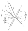
- Fig. 1 is a perspective view of a device body 10 of a micro device according to an embodiment of the present invention
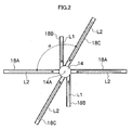
- Fig. 2 is a sectional view of a confluent part and therearound in Fig. 1 .
- the micro device includes at least a supply device that supplies a liquid in the device body 10.
- the device body 10 of the micro device of the present embodiment includes a supply channel portion 12 for two kinds of liquids "A” and “B", a confluent part 14 in which the two kinds of liquids “A” and “B” are joined through the supply channel portion 12, and a discharge channel portion 16 that discharges a confluent liquid LM obtained by joining.
- the supply channel portion 12 two channel units 18 are arranged around a cylindrical confluent part 14 with one end closed, each channel unit 18 including three supply channels 18A, 18B and 18C for joining the liquids so as to sandwich one flow of the liquid "A" between two flows of the liquid "B".
- An upper limit of a number of the channel units 18 that can be arranged around the confluent part 14 is determined according to a size (sectional area) of the confluent part 14.
- the number of the channel units 18 is preferably equal to or greater than two and equal to or less than four.
- the channel unit 18 joins the liquids into the confluent part so as to sandwich one flow of liquid L1 between two flows of liquid L2 to form a contracted liquid S constituted by the flow of liquid L1 contracted by the flows of liquid L2.
- the two supply channels 18A and 18C for sandwiching preferably form an obtuse angle ⁇ (larger than 90° and smaller than 180°). This can increase the degree of contraction.
- the two channel units 18 are arranged in symmetrical positions with respect to a confluent part center 14A around the confluent part 14, and a flow-in direction of the contracted liquid S flowing from each of the two channel units 18 into the confluent part 14 is offset from the confluent part center 14A.
- each channel unit 18 is arranged so that central axes of the supply channels 18A, 18B and 18C do not pass thorough the confluent part center 14A.
- the flow-in direction of the contracted liquid S formed by the channel unit 18 is offset to generate a swirling flow in the confluent part 14.
- the two channel units 18 are arranged in the point-symmetrical positions to generate two swirling energies for generating the swirling flows in two positions which are at 180° opposite positions in the confluent part 14 to increase strength of the swirling flows.
- the swirling flow by the contracted liquid S is generated in the confluent part 14, thereby allowing instantaneous mixing of the liquids L1 and L2 that constitute the contracted liquid S.
- the discharge channel portion 16 includes one cylindrical discharge channel 20, and is formed continuously with the cylindrical confluent part 14.
- the discharge channel 20 has such a length L that can ensure a distance for a mixing rate of the confluent liquid LM joined in the confluent part 14 to reach an upper limit and to reach a state of equilibrium.
- the length L is preferably about 10 mm.
- an equivalent diameter of the supply channels 18A to 18C is preferably 10 ⁇ m or more and 1000 ⁇ m or less.
- the equivalent diameter of the cylindrical confluent part 14 may be relatively large and is preferably 0.1 mm or more and 10 mm or less.
- the discharge channel 20 preferably has an equivalent diameter equal to or larger than that of the confluent part 14 so as to quickly discharge the confluent liquid LM joined in the confluent part 14.
- the equivalent diameter is also referred to as equilibrium diameter, and is a term used in the field of machine engineering.
- a diameter of the equivalent circular pipe is referred to as an equivalent diameter.
- deq 4A/p
- A is a sectional area of a pipe
- p is a wetted perimeter length (perimeter length) of the pipe
- the equivalent diameter matches the diameter of the circular pipe.
- the equivalent diameter is used for estimating a flow or heat transfer characteristic of the pipe on the basis of data on the equivalent circular pipe, and the equivalent diameter indicates a spatial scale (representative length) of a phenomenon.
- the supply channels 18A to 18C each have a square sectional shape, but not limited to this, and may have various shapes such as a circular, semi-circular, or inversed trapezoidal shape.
- the discharge channel 20 preferably has the same circular sectional shape as the confluent part 14 so as to efficiently transfer the swirling flow generated in the confluent part 14.
- the discharge channel 20 with a circular shape can also reduce dead space.
- a supply device that supplies the liquids L1 and L2 to the supply channels 18A to 18C
- a micro syringe pump can be suitably used.
- a heating device (not illustrated) that heats the device body 10 of the micro device is provided as required.
- the heating device there is a method of incorporating a heater structure including a metal resistance wire or polysilicon or the like into the device body. When the heater structure including the metal resistance wire or polysilicon or the like is used, a thermal cycle is performed by using the heater structure for heating and using natural cooling for cooling to control temperature.
- the metal resistance wire when the metal resistance wire is used, one more metal resistance wire which is of the same sort as that included in the heater structure is incorporated to detect the temperature on the basis of a change in resistance value thereof. And when the polysilicon is used, a thermocouple is used to detect the temperature. A temperature control function using a Peltier device may be incorporated into the device body.
- organic solvent such as water, acid solution, alkaline solution, methanol, ethanol or dimethyl sulfoxide, a mixture of these liquids, or a dispersed liquid that is the above described liquids or the mixture having particulates dispersed therein can be suitably used.
- the particulate refers to a particle having a diameter of 1 ⁇ m or less.
- the liquids L1 and L2 preferably have low viscosity in terms of mixing performance and pressure loss, and more specifically, the liquids preferably have viscosity of 30 cp or less.
- the liquids "A" and "B” are preferably used at a flow rate of 1 to 1000 cc/min.
- the three liquids that constitute the contracted liquid S include two kinds of liquids: one sandwiched liquid L1 and two sandwiching liquids L2, but all the three liquids that constitute the contracted liquid S may be of different kinds.
- the liquids passed through the channel units 18 preferably have the same kind constitution, but may have different kind constitutions.
- a liquid passed through one channel unit 18 and a liquid passed through another channel unit 18 may be of different kinds. The same applies to the case with three or more channel units 18.
- each channel unit 18 includes the three supply channels 18A to 18C that join the flows of liquids so as to sandwich one flow of liquid L1 between two flows of liquid L2.
- the contracted liquid S constituted by the middle flow of liquid L1 sandwiched between the flows of liquid L2 on opposite sides is formed in the confluent part 14.
- a flow-in direction of the liquids L1 and L2 flowing from the channel unit 18 into the confluent part 14, that is, the contracted liquid S is offset from the confluent part center 14A, and thus the swirling flow of the contracted liquid S is generated in the confluent part 14.
- FIG. 3A shows the liquids L1 and L2 flowing through the three supply channels 18A to 18C being supplied at the same speed of 1 m/sec, and the swirling flow of the contracted liquid S is formed around the confluent part center 14A.
- the center of the swirling flow is substantially identical to the confluent part center 14A.
- Fig. 3B shows the liquids L1 and L2 flowing through the three supply channels 18A to 18C being supplied at different speeds, and the center of the swirling flow is offset from the confluent part center 14A.
- the lightest color shows the flow of the liquid L2
- the second lightest color shows the flow of the liquid L1
- the darkest color shows the liquids L1 and L2 being mixed.
- the swirling flow can apply a high shearing force between the flows of liquids L1 and L2 that constitute the contracted liquid S, and also generates a suction flow of the contracted liquid S sucked from the confluent part center 14A into the discharge channel 20.
- the contracted liquid S is pulled by the suction flow, and the middle flow of liquid L1 in the contracted liquid S is particularly contracted to be tapered.
- the contracted liquid S formed by the channel unit 18 When the flow-in direction of the contracted liquid S formed by the channel unit 18 is directed to the confluent part center 14A, the contracted liquid S easily expands in the confluent part 14 having the larger diameter than the supply channels 18A to 18C, thereby preventing the contraction of the contracted liquid S from being maintained.
- the contracted liquid S when the contracted liquid S is swirled in the confluent part 14 as described in the embodiment, the flow of contracted liquid S is pressed against an inner wall of the confluent part 14, thereby preventing the expansion and further facilitating the contraction.
- the contracted liquid S formed by the channel unit 18 is further contracted by the swirling flow, and thus the middle flow of liquid L1 sandwiched between the two flows of liquid L2 is contracted to be tapered in the confluent part 14 to increase a mixing rate of the liquids L1 and L2.
- the contracted liquid S is further contracted by the swirling flow to maintain the contraction from the confluent part 14 toward the discharge channel 20, thereby providing high mixing efficiency even with a relatively large diameter of the confluent part 14.
- the contracted liquid S is further contracted by the swirling flow to prevent the influence on mixing performance even if flow ratios of the three flows of liquids L1 and L2 that constitute the contracted liquid S are not equal to each other, that is, even if a flow balance changes.
- the channel unit 18 has the structure in which the flows of liquid L2 contracts the flow of liquid L1, and thus there is no need for narrowing confluent part inlets of the supply channels 18A to 18C to prevent an increase in pressure loss.
- a micro device also referred to as reactor
- a micro device including two channel units 18, each channel unit 18 including three supply channels 18A to 18C, and one discharge channel 20 in a device body 10.
- the three supply channels 18A to 18C that constitute the channel unit 18 each had a square section with a size of 0.4 mm x 0.4 mm.
- one supply channel 18B that passes a liquid L1 had a length of 3 mm
- two supply channels 18A and 18C that pass a liquid L2 each had a length of 5.3 mm.
- An angle ⁇ between the two supply channels 18A and 18C for sandwiching was 120°.
- a confluent part 14 was formed into a cylindrical shape having a diameter of 1.1 mm and a depth of 0.4 mm.
- the discharge channel 20 was formed into a cylindrical shape having the same diameter of 1.1 mm as the confluent part 14 and a length of 10 mm.
- a KM reactor 30 was used as a conventional reactor in Fig. 4 .
- a device body 31 of the KM reactor 30 three supply channels 32A, 32B and 32C that pass a liquid L1 and three supply channels 34A, 34B and 34C that pass a liquid L2 are joined in a confluent part 36, and the liquids are discharged from a discharge channel 38.
- the six channels 32A to 32C and 34A to 34C are radially extended from a center 36A of the confluent part 36, angles between the channels are all 60°, and the liquids L1 and L2 flowing from the six channels 32A to 32C and 34A to 34C into the confluent part 36 collide with each other in the confluent part center 36A.
- the KM reactor 30 is not configured so that a flow-in direction of liquids flowing into a confluent part 14 is offset from the confluent part center 14A as in the present embodiment.
- the three supply channels 32A to 32C that pass the liquid L1 had a size of 0.4 mm x 0.2 mm and a length of 3 mm.
- the three supply channels 34A to 34C that pass the liquid L2 had a size of 0.4 mm x 0.4 mm and a length of 5.3 mm.
- the confluent part 36 was formed into a cylindrical shape having a diameter of 0.8 mm and a depth of 0.4 mm.
- the discharge channel 38 was formed into a cylindrical shape having the same diameter of 0.8 mm as the confluent part 36 and a length of 10 mm.
- DMSO dimethyl sulfoxide
- a flow rate thereof was set to 500 cc/min (cubic centimeter per minute) as simulation conditions.
- water was used as the liquid L2, and a flow rate thereof was set to 1000 cc/min.
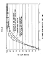
- the test results are shown in Fig. 5 .
- a mixing rate when there are flow rate variations in the micro device 10 of the present embodiment was also tested. Specifically, it is checked that whether combination use of two actions, that is, contraction and swirling which are the features of the present embodiment can reduces the influence of the flow rate variations on a mixing rate.
- the mixing rate is a percentage of a mixing rate when complete mixing of the liquids L1 and L2 is 100%.
- a flow rate of one of the supply channels 18B was set to 375 cc/min and a flow rate of the other was set to 625 cc/min so that variations of 25% occur.
- a flow rate of one of the supply channels was set to 500 cc/min and a flow rate of the other was set to 1500 cc/min so that variations of 50% occur.
- the reactor of the present embodiment (without flow rate variations) could achieve a mixing rate equal to or higher than that of the conventional KM reactor. It could be also confirmed that there is little influence on the mixing rate even if there are flow rate variations as the reactor of the present embodiment (with flow rate variations).
- a pressure loss test for checking a reduction in pressure loss as the feature of the micro device of the present embodiment was conducted and compared with the conventional KM reactor.
- the configuration of the reactor used in the pressure loss test was the same as in the mixing performance test for both the present embodiment and the comparative example.
- DMSO Dimethyl sulfoxide
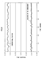
- Fig. 5 shows results of pressure loss when only the liquid L2 is passed and immediately before the liquid L1 is passed.
- Fig. 7 shows results of pressure loss when only the liquid L1 is passed and immediately before the liquid L2 is passed.
- the pressure loss is remarkably reduced in the micro device of the present embodiment as compared with the conventional KM reactor. Specifically, it is supposed that the micro device of the present embodiment joins the flows of liquids into the confluent part so as to sandwich one flow of liquid between two flows of liquid to form the contracted liquid in the confluent part, thereby effectively preventing an increase in pressure loss.
- the micro device of the present embodiment can maintain higher mixing performance, prevent the mixing performance from being influenced by flow rate variations, and further reduce pressure loss, as compared with the conventional KM reactor.
Landscapes
- Chemical & Material Sciences (AREA)
- Chemical Kinetics & Catalysis (AREA)
- Physical Or Chemical Processes And Apparatus (AREA)
- Micromachines (AREA)
Abstract
Description
- The present invention relates to a micro device and a liquid mixing method, and more particularly to a micro device and a liquid mixing method for passing multiple kinds of liquids through independent supply channels to be joined into a confluent part and mixing the liquids (including reaction by mixing).
- A so-called micro device (also referred to as a microreactor or a micromixer) for performing mixing or reaction while precisely controlling liquids in a minute space has recently received attention. A specific surface area of the micro device is increased by a scale-down, and thus molecules are moved by only diffusion. This allows collision between molecules to be precisely controlled.
- There is a two-stage reaction process in which, for example, all molecules are reacted in a first stage and agglomeration of the reacted molecules is prevented in a second stage. In this case, mixing needs to be instantaneously completed in the first stage. However, in the conventional micro device, only molecule diffusion contributes to velocity components perpendicular to a mainstream direction, and thus such reaction is difficult to handle.
- Thus, Japanese Patent Application Laid-Open No.
2006-167600 - Also, "Chemical Micro Process Engineering", V. Hessel et al., WILEY-VCH Verlag GmbH & Co. KGaA discloses a cyclone mixer including a plurality of nozzles for injecting liquids into a confluent part.
- However, the micromixer described in Japanese Patent Application Laid-Open No.
2006-167600 - For instantaneously mixing multiple kinds of liquids in a confluent part, it is preferable that a diameter of the confluent part is reduced and the multiple liquids are brought into contact with each other in thin film form. Thus, reducing (narrowing) a diameter of a confluent part inlet of a supply channel has been proposed. However, reducing the diameter of the confluent part inlet of the supply channel increases pressure loss.
- The present invention is achieved in view of such circumstances, and provides a micro device and a liquid mixing method that can quickly and efficiently mix multiple kinds of liquids without increasing pressure loss.
- To achieve the above described object, a first aspect of the present invention provides a micro device including: a supply channel portion; a confluent part into which multiple kinds of liquids flow from the supply channel portion to join flows of the liquids from the supply channel portion; and a discharge channel portion through which a confluent liquid obtained by joining the flows of liquids is discharged, wherein the supply channel portion includes one or more channel units arranged around the confluent part, each of the channel units including three supply channels for joining the multiple kinds of liquids so as to sandwich one flow of liquid between two flows of liquid, and a flow-in direction of the liquids flowing from each of the channel units into the confluent part is offset from the center of the confluent part.
- According to the micro device of the aspect of the present invention, one or more channel units are arranged around the confluent part, and each channel includes the three supply channels for joining the multiple kinds of liquids so as to sandwich one liquid between two liquids. Therefore, a contracted liquid constituted by a contracted thin middle liquid sandwiched between liquids on opposite sides is formed in the confluent part. Thus, the three liquids that constitute the contracted liquid are joined in thin film form to increase mixing efficiency. Therefore, instantaneous mixing of the three liquids is achieved. In the aspect of the present invention, a diameter of the supply channel is not narrowed to form the contraction, but the two liquids sandwich the middle liquid to form the contracted liquid. Therefore, mixing efficiency can be increased without increasing pressure loss in the supply channel.
- Further, the flow-in direction of the liquid flowing from the channel unit into the confluent part, that is, the contracted liquid is offset from the center of the confluent part. Therefore, a swirling flow of the contracted liquid is generated in the confluent part. The swirling flow can apply a high shearing force between the liquids that constitute the contracted liquid, and also generates a suction flow of the contracted liquid sucked from the center of the confluent part into the discharge channel portion. Thus, the contracted liquid formed by the channel unit is pulled by the swirling flow, and the middle liquid sandwiched between the two liquids in the contracted liquid is contracted to be tapered. Thus, the three liquids that constitute the contracted liquid are further made into thinner film form, thereby further increasing mixing efficiency and allowing instantaneous mixing.
- As such, in the present invention, the contracted liquid formed by the channel unit is further contracted by the swirling flow to maintain a contraction condition in the confluent part, and thus the liquids can be efficiently mixed even with a relatively large diameter of the confluent part. Further, when the two liquids sandwich the middle liquid to form the contracted liquid as in the aspect of the present invention, an imbalance in flow rates of the two sandwiching liquids may reduce a contraction effect to reduce mixing efficiency, but a combination with the swirling flow prevents the reduction in mixing efficiency even with the imbalance in flow rates.
- In the aspect of the present invention, the three liquids that constitute the contracted liquid preferably include two kinds of liquids: two sandwiching liquids A and one sandwiched liquid B mixed together, but all the three liquids may be of different kinds. When two channel units are provided, the liquids passed through the channel units preferably have the same kind constitution, but may have different kind constitutions. The same applies to the case with three or more channel units. The aspect of the present invention describes mixing the liquids in the confluent part, but also includes reaction by mixing.
- In the micro device of the aspect of the present invention, among the three supply channels that constitute the channel unit, the two supply channels for sandwiching preferably form an obtuse angle (the second aspect). This can increase contribution of kinetic energy of the two sandwiching liquids to the contraction of the middle liquid, thereby increasing the degree of contraction and further increasing mixing efficiency.
- In the micro device of the aspects of the present invention, two channel units are preferably provided in symmetrical positions with respect to the center of the confluent part (the third aspect). Thus, swirling flows of two contracted liquids are generated in the confluent part in symmetrical positions with respect to the center of the confluent part, thereby further increasing mixing efficiency.
- In the micro device of the aspects of the present invention, the confluent part in the micro space preferably has a diameter of 0.1 mm to 10 mm (the fourth aspect). In the aspect of the present invention, as described above, the confluent part may have a relatively large diameter, but a diameter of larger than 10 mm may significantly reduce mixing efficiency.
- To achieve the above described object, a fifth aspect of the present invention provides a liquid mixing method including steps of: joining flows of multiple kinds of liquids flowing from a supply channel portion into a confluent part; forming at least one contracted liquid (S) in the confluent part, and contracting the contracted liquid by joining the flows of multiple kinds of liquids from the supply channel portion into the confluent part so as to sandwich one flow of liquid (L1) between two flows of liquid (L2); generating a swirling flow of the contracted liquid in the confluent part by offsetting a flow-in direction of the contracted liquid into the confluent part from the center of the confluent part; and discharging the contracted liquid obtained by joining the flows of liquids from the confluent part through a discharge channel portion.
- According to the liquid mixing method of the fifth aspect of the present invention, the swirling flow of the contracted liquid is generated in the confluent part, and thus the operation described for the micro device occurs. Thus, multiple kinds of liquids may be quickly and efficiently mixed without increasing pressure loss.
- In the liquid mixing method of the aspect of the present invention, two contracted liquids are preferably formed in symmetrical positions with respect to the center of the confluent part (the sixth aspect). Thus, swirling flows of the two contracted liquids are generated in the confluent part in 180° opposite positions around the confluent part center, thereby mixing efficiency is further increased.
- In the liquid mixing method of the aspects of the present invention, flow rates of the multiple kinds of liquids introduced into the confluent part are preferably controlled so that the center of swirling of the swirling flow matches the center of the confluent part (the seventh aspect). This can increase a pulling force of the contracted liquid sucked by a suction flow from the center of the confluent part into the discharge channel portion, thereby contraction by the swirling flow is provided effectively.
- In the liquid mixing method of the aspects of the present invention, the liquid preferably has viscosity of 30 cp or less (the eighth aspect). The low viscosity of 30 cp or less of the liquid further facilitates mixing of the liquids and further reducing pressure loss.
- According to the micro device and the liquid mixing method of the aspects of the present invention, the multiple kinds of liquids can be quickly and efficiently mixed without increasing pressure loss.
-
-
Fig. 1 is a perspective view of an example of a device body of a micro device according to an embodiment of the present invention; -
Fig. 2 is a sectional view illustrating a supply channel and a confluent part inFig. 1 ; -
Figs. 3A and 3B illustrate an operation of the embodiment of the present invention; -
Fig. 4 is a perspective view of a device body of a conventional KM reactor; -
Fig. 5 illustrates an example of a mixing rate of the micro device of the embodiment of the present invention as compared with a conventional device; -
Fig. 6 illustrates an example of pressure loss of the micro device of the embodiment of the present invention as compared with the conventional device; and -
Fig. 7 illustrates an example of pressure loss of the micro device of another embodiment of the present invention as compared with the conventional device. - Now, preferred embodiments of a micro device and a liquid mixing method according to the present invention will be described with reference to the accompanying drawings.
-
Fig. 1 is a perspective view of adevice body 10 of a micro device according to an embodiment of the present invention, andFig. 2 is a sectional view of a confluent part and therearound inFig. 1 . In this embodiment, the case of mixing two kinds of liquids "A" and "B" will be described. The micro device includes at least a supply device that supplies a liquid in thedevice body 10. - As shown in
Figs. 1 and2 , thedevice body 10 of the micro device of the present embodiment includes asupply channel portion 12 for two kinds of liquids "A" and "B", aconfluent part 14 in which the two kinds of liquids "A" and "B" are joined through thesupply channel portion 12, and adischarge channel portion 16 that discharges a confluent liquid LM obtained by joining. In thesupply channel portion 12, twochannel units 18 are arranged around a cylindricalconfluent part 14 with one end closed, eachchannel unit 18 including threesupply channels channel units 18 that can be arranged around theconfluent part 14 is determined according to a size (sectional area) of theconfluent part 14. The number of thechannel units 18 is preferably equal to or greater than two and equal to or less than four. - As such, the
channel unit 18 joins the liquids into the confluent part so as to sandwich one flow of liquid L1 between two flows of liquid L2 to form a contracted liquid S constituted by the flow of liquid L1 contracted by the flows of liquid L2. As shown inFig. 2 , among the threesupply channels channel unit 18, the twosupply channels channel units 18 are arranged in symmetrical positions with respect to aconfluent part center 14A around theconfluent part 14, and a flow-in direction of the contracted liquid S flowing from each of the twochannel units 18 into theconfluent part 14 is offset from theconfluent part center 14A. For example, eachchannel unit 18 is arranged so that central axes of thesupply channels confluent part center 14A. The flow-in direction of the contracted liquid S formed by thechannel unit 18 is offset to generate a swirling flow in theconfluent part 14. The twochannel units 18 are arranged in the point-symmetrical positions to generate two swirling energies for generating the swirling flows in two positions which are at 180° opposite positions in theconfluent part 14 to increase strength of the swirling flows. - As such, the swirling flow by the contracted liquid S is generated in the
confluent part 14, thereby allowing instantaneous mixing of the liquids L1 and L2 that constitute the contracted liquid S. - Meanwhile, the
discharge channel portion 16 includes onecylindrical discharge channel 20, and is formed continuously with the cylindricalconfluent part 14. Thedischarge channel 20 has such a length L that can ensure a distance for a mixing rate of the confluent liquid LM joined in theconfluent part 14 to reach an upper limit and to reach a state of equilibrium. Generally, the length L is preferably about 10 mm. Specifically, mixing of the two kinds of liquids L1 and L2 joined in theconfluent part 14 is started in theconfluent part 14, and instantaneous mixing is performed in a short time for the liquids to flow through thedischarge channel 20 whose length is about 10 mm. Thus, when the liquids L1 and L2 are also reacted, the reaction is completed while the liquids flow through thedischarge channel 20. - As to the size of the channels used in the micro device of the present embodiment, in order to achieve quick mixing and precise control of reaction, an equivalent diameter of the
supply channels 18A to 18C is preferably 10 µm or more and 1000 µm or less. In the present embodiment, the equivalent diameter of the cylindricalconfluent part 14 may be relatively large and is preferably 0.1 mm or more and 10 mm or less. Thedischarge channel 20 preferably has an equivalent diameter equal to or larger than that of theconfluent part 14 so as to quickly discharge the confluent liquid LM joined in theconfluent part 14. - The equivalent diameter is also referred to as equilibrium diameter, and is a term used in the field of machine engineering. When an equivalent circular pipe with respect to a pipe (channel in the present embodiment) having an arbitrary sectional shape is supposed, a diameter of the equivalent circular pipe is referred to as an equivalent diameter. The equivalent diameter (deq) is defined as deq = 4A/p, where "A" is a sectional area of a pipe and "p" is a wetted perimeter length (perimeter length) of the pipe When applied to the circular pipe, the equivalent diameter matches the diameter of the circular pipe. The equivalent diameter is used for estimating a flow or heat transfer characteristic of the pipe on the basis of data on the equivalent circular pipe, and the equivalent diameter indicates a spatial scale (representative length) of a phenomenon. The equivalent diameter is deq = 4a2/4a = a for a square pipe with each side of "a", deq = a/31/2 for a regular triangular pipe with each side of "a", and deq = 2h for a flow between parallel flat plates with a channel height "h" (for example, see "Dictionary of machine engineering", edited by The Japan Society of Mechanical Engineers, 1997, Maruzen Co., Ltd.).
- In
Fig. 1 , thesupply channels 18A to 18C each have a square sectional shape, but not limited to this, and may have various shapes such as a circular, semi-circular, or inversed trapezoidal shape. When theconfluent part 14 is formed into the cylindrical shape as described above, thedischarge channel 20 preferably has the same circular sectional shape as theconfluent part 14 so as to efficiently transfer the swirling flow generated in theconfluent part 14. Thedischarge channel 20 with a circular shape can also reduce dead space. - As a supply device that supplies the liquids L1 and L2 to the
supply channels 18A to 18C, for example, a micro syringe pump can be suitably used. Also, a heating device (not illustrated) that heats thedevice body 10 of the micro device is provided as required. As the heating device, there is a method of incorporating a heater structure including a metal resistance wire or polysilicon or the like into the device body. When the heater structure including the metal resistance wire or polysilicon or the like is used, a thermal cycle is performed by using the heater structure for heating and using natural cooling for cooling to control temperature. In this case, generally, when the metal resistance wire is used, one more metal resistance wire which is of the same sort as that included in the heater structure is incorporated to detect the temperature on the basis of a change in resistance value thereof. And when the polysilicon is used, a thermocouple is used to detect the temperature. A temperature control function using a Peltier device may be incorporated into the device body. - As the specific kinds of the liquids L1 and L2 used in the embodiment, organic solvent such as water, acid solution, alkaline solution, methanol, ethanol or dimethyl sulfoxide, a mixture of these liquids, or a dispersed liquid that is the above described liquids or the mixture having particulates dispersed therein can be suitably used. The particulate refers to a particle having a diameter of 1 µm or less.
- The liquids L1 and L2 preferably have low viscosity in terms of mixing performance and pressure loss, and more specifically, the liquids preferably have viscosity of 30 cp or less. The liquids "A" and "B" are preferably used at a flow rate of 1 to 1000 cc/min.
- In this embodiment, the three liquids that constitute the contracted liquid S include two kinds of liquids: one sandwiched liquid L1 and two sandwiching liquids L2, but all the three liquids that constitute the contracted liquid S may be of different kinds. When two
channel units 18 are provided, the liquids passed through thechannel units 18 preferably have the same kind constitution, but may have different kind constitutions. Specifically, a liquid passed through onechannel unit 18 and a liquid passed through anotherchannel unit 18 may be of different kinds. The same applies to the case with three ormore channel units 18. - Next, an operation of the micro device configured as described above will be described.
- According to the micro device configured as described above, the two
channel units 18 arranged around theconfluent part 14 eachchannel unit 18 includes the threesupply channels 18A to 18C that join the flows of liquids so as to sandwich one flow of liquid L1 between two flows of liquid L2. Thus, as shown inFigs. 3A and 3B , the contracted liquid S constituted by the middle flow of liquid L1 sandwiched between the flows of liquid L2 on opposite sides is formed in theconfluent part 14. Further, a flow-in direction of the liquids L1 and L2 flowing from thechannel unit 18 into theconfluent part 14, that is, the contracted liquid S is offset from theconfluent part center 14A, and thus the swirling flow of the contracted liquid S is generated in theconfluent part 14.Fig. 3A shows the liquids L1 and L2 flowing through the threesupply channels 18A to 18C being supplied at the same speed of 1 m/sec, and the swirling flow of the contracted liquid S is formed around theconfluent part center 14A. In this case, the center of the swirling flow is substantially identical to theconfluent part center 14A.Fig. 3B shows the liquids L1 and L2 flowing through the threesupply channels 18A to 18C being supplied at different speeds, and the center of the swirling flow is offset from theconfluent part center 14A. InFigs. 3A and 3B , the lightest color shows the flow of the liquid L2, the second lightest color shows the flow of the liquid L1, and the darkest color shows the liquids L1 and L2 being mixed. - The swirling flow can apply a high shearing force between the flows of liquids L1 and L2 that constitute the contracted liquid S, and also generates a suction flow of the contracted liquid S sucked from the
confluent part center 14A into thedischarge channel 20. The contracted liquid S is pulled by the suction flow, and the middle flow of liquid L1 in the contracted liquid S is particularly contracted to be tapered. - When the flow-in direction of the contracted liquid S formed by the
channel unit 18 is directed to theconfluent part center 14A, the contracted liquid S easily expands in theconfluent part 14 having the larger diameter than thesupply channels 18A to 18C, thereby preventing the contraction of the contracted liquid S from being maintained. In contrast, when the contracted liquid S is swirled in theconfluent part 14 as described in the embodiment, the flow of contracted liquid S is pressed against an inner wall of theconfluent part 14, thereby preventing the expansion and further facilitating the contraction. - As such, the contracted liquid S formed by the
channel unit 18 is further contracted by the swirling flow, and thus the middle flow of liquid L1 sandwiched between the two flows of liquid L2 is contracted to be tapered in theconfluent part 14 to increase a mixing rate of the liquids L1 and L2. The contracted liquid S is further contracted by the swirling flow to maintain the contraction from theconfluent part 14 toward thedischarge channel 20, thereby providing high mixing efficiency even with a relatively large diameter of theconfluent part 14. The contracted liquid S is further contracted by the swirling flow to prevent the influence on mixing performance even if flow ratios of the three flows of liquids L1 and L2 that constitute the contracted liquid S are not equal to each other, that is, even if a flow balance changes. Further, thechannel unit 18 has the structure in which the flows of liquid L2 contracts the flow of liquid L1, and thus there is no need for narrowing confluent part inlets of thesupply channels 18A to 18C to prevent an increase in pressure loss. - Next, simulation tests conducted for evaluating mixing performance and pressure loss of the micro device and the fluid mixing method of the present embodiment will be described. An analysis software used for the simulation tests is "FLUENT: version 6.3" by ANSYS Japan K.K.
- In the simulation, as shown in
Fig. 1 , a micro device (also referred to as reactor) was used including twochannel units 18, eachchannel unit 18 including threesupply channels 18A to 18C, and onedischarge channel 20 in adevice body 10. - The three
supply channels 18A to 18C that constitute thechannel unit 18 each had a square section with a size of 0.4 mm x 0.4 mm. Among thesupply channels 18A to 18C, onesupply channel 18B that passes a liquid L1 had a length of 3 mm, and twosupply channels supply channels - Meanwhile, a
confluent part 14 was formed into a cylindrical shape having a diameter of 1.1 mm and a depth of 0.4 mm. Thedischarge channel 20 was formed into a cylindrical shape having the same diameter of 1.1 mm as theconfluent part 14 and a length of 10 mm. - For comparison, a
KM reactor 30 was used as a conventional reactor inFig. 4 . As is clear fromFig. 4 , in adevice body 31 of theKM reactor 30, threesupply channels supply channels confluent part 36, and the liquids are discharged from adischarge channel 38. However, the sixchannels 32A to 32C and 34A to 34C are radially extended from acenter 36A of theconfluent part 36, angles between the channels are all 60°, and the liquids L1 and L2 flowing from the sixchannels 32A to 32C and 34A to 34C into theconfluent part 36 collide with each other in theconfluent part center 36A. Specifically, theKM reactor 30 is not configured so that a flow-in direction of liquids flowing into aconfluent part 14 is offset from theconfluent part center 14A as in the present embodiment. - In the
KM reactor 30 used, the threesupply channels 32A to 32C that pass the liquid L1 had a size of 0.4 mm x 0.2 mm and a length of 3 mm. The threesupply channels 34A to 34C that pass the liquid L2 had a size of 0.4 mm x 0.4 mm and a length of 5.3 mm. Theconfluent part 36 was formed into a cylindrical shape having a diameter of 0.8 mm and a depth of 0.4 mm. Thedischarge channel 38 was formed into a cylindrical shape having the same diameter of 0.8 mm as theconfluent part 36 and a length of 10 mm. - For both the present embodiment and the comparative example, dimethyl sulfoxide (DMSO) was used as the liquid L1, and a flow rate thereof was set to 500 cc/min (cubic centimeter per minute) as simulation conditions. Also, water was used as the liquid L2, and a flow rate thereof was set to 1000 cc/min.
- The test results are shown in
Fig. 5 . In the mixing performance test, in addition to comparison between a mixing rate in the use of themicro device 10 of the present embodiment and a mixing rate in the use of theconventional KM reactor 30, a mixing rate when there are flow rate variations in themicro device 10 of the present embodiment was also tested. Specifically, it is checked that whether combination use of two actions, that is, contraction and swirling which are the features of the present embodiment can reduces the influence of the flow rate variations on a mixing rate. The mixing rate is a percentage of a mixing rate when complete mixing of the liquids L1 and L2 is 100%. - For the reactor of the present embodiment (without flow rate variations) in
Fig. 5 , the same flow rate of 500 cc/min of the liquid L1 was passed through the two supply channels and the same flow rate of 1000 cc/min of the liquid L2 was passed through the four supply channels so that the liquids L1 and L2 are evenly supplied to the respective supply channels. - For the reactor of the present embodiment (with flow rate variations), among the two
supply channels 18B that pass the liquid L1, a flow rate of one of thesupply channels 18B was set to 375 cc/min and a flow rate of the other was set to 625 cc/min so that variations of 25% occur. Also, among the twosupply channels - Thus, as is clear from
Fig. 5 , the reactor of the present embodiment (without flow rate variations) could achieve a mixing rate equal to or higher than that of the conventional KM reactor. It could be also confirmed that there is little influence on the mixing rate even if there are flow rate variations as the reactor of the present embodiment (with flow rate variations). - Also, a pressure loss test for checking a reduction in pressure loss as the feature of the micro device of the present embodiment was conducted and compared with the conventional KM reactor. The configuration of the reactor used in the pressure loss test was the same as in the mixing performance test for both the present embodiment and the comparative example.
- Dimethyl sulfoxide (DMSO) was used as the liquid L1 in the test, and a flow rate thereof was set to 100 cc/min. Also, water was used as the liquid L2, and a flow rate thereof was set to 200 cc/min, and the liquids were actually supplied to measure pressure loss.
- The test results are shown in
Fig. 5 .Fig. 6 shows results of pressure loss when only the liquid L2 is passed and immediately before the liquid L1 is passed.Fig. 7 shows results of pressure loss when only the liquid L1 is passed and immediately before the liquid L2 is passed. - As is clear from
Figs. 6 and7 , it was confirmed that the pressure loss is remarkably reduced in the micro device of the present embodiment as compared with the conventional KM reactor. Specifically, it is supposed that the micro device of the present embodiment joins the flows of liquids into the confluent part so as to sandwich one flow of liquid between two flows of liquid to form the contracted liquid in the confluent part, thereby effectively preventing an increase in pressure loss. - As described above, it became apparent that the micro device of the present embodiment can maintain higher mixing performance, prevent the mixing performance from being influenced by flow rate variations, and further reduce pressure loss, as compared with the conventional KM reactor.
Claims (8)
- A micro device (10) comprising:a supply channel portion (12);a confluent part (14) into which multiple kinds of liquids (L1, L2) flow from the supply channel portion to join flows of the liquids from the supply channel portion; anda discharge channel portion (16) through which a confluent liquid obtained by joining the flows of liquids is discharged,
wherein the supply channel portion includes one or more channel units (18) arranged around the confluent part, each of the channel units including three supply channels (18A, 18B, 18C) for joining the multiple kinds of liquids so as to sandwich one flow of liquid (L1) between two flows of liquid (L2), anda flow-in direction of the liquids flowing from each of the channel units into the confluent part is offset from the center (14C) of the confluent part. - The micro device according to claim 1, wherein among the three supply channels that constitute the channel unit, two supply channels (18A, 18C) for sandwiching one supply channel (18B) form an obtuse angle.
- The micro device according to claim 1 or 2, wherein two channel units are provided in point-symmetrical positions with respect to the center of the confluent part.
- The micro device according to any one of claims 1 to 3, wherein the confluent part is a micro space, and has an equivalent diameter of 0.1 mm to 10 mm.
- A liquid mixing method comprising steps of:joining flows of multiple kinds of liquids (L1, L2) flowing from a supply channel portion (12) into a confluent part (14);forming at least one contracted liquid (S) in the confluent part, and contracting the contracted liquid by joining the flows of multiple kinds of liquids from the supply channel portion into the confluent part so as to sandwich one flow of liquid (L1) between two flows of liquid (L2);generating a swirling flow of the contracted liquid in the confluent part by offsetting a flow-in direction of the contracted liquid into the confluent part from the center (14A) of the confluent part; anddischarging the contracted liquid obtained by joining the flows of liquids (L1, L2) from the confluent part through a discharge channel portion (16).
- The liquid mixing method according to claim 5, wherein the forming step includes step of forming two contracted liquids in point-symmetrical positions with respect to the center of the confluent part.
- The liquid mixing method according to claim 5 or 6, further comprising step of controlling flow rates of the multiple kinds of liquids introduced into the confluent part so that the center of swirling of the swirling flow matches the center of the confluent part.
- The liquid mixing method according to any one of claims 5 to 7, wherein the liquid (L1, L2) has viscosity of 30 cp or less.
Applications Claiming Priority (1)
| Application Number | Priority Date | Filing Date | Title |
|---|---|---|---|
| JP2008250892A JP2010082491A (en) | 2008-09-29 | 2008-09-29 | Micro device and method for mixing liquid |
Publications (2)
| Publication Number | Publication Date |
|---|---|
| EP2168671A2 true EP2168671A2 (en) | 2010-03-31 |
| EP2168671A3 EP2168671A3 (en) | 2011-03-23 |
Family
ID=41508744
Family Applications (1)
| Application Number | Title | Priority Date | Filing Date |
|---|---|---|---|
| EP09012150A Withdrawn EP2168671A3 (en) | 2008-09-29 | 2009-09-24 | Micro device and liquid mixing method |
Country Status (2)
| Country | Link |
|---|---|
| EP (1) | EP2168671A3 (en) |
| JP (1) | JP2010082491A (en) |
Citations (1)
| Publication number | Priority date | Publication date | Assignee | Title |
|---|---|---|---|---|
| JP2006167600A (en) | 2004-12-16 | 2006-06-29 | Nikkiso Co Ltd | Micromixer, micromixer chip and microsensor |
Family Cites Families (5)
| Publication number | Priority date | Publication date | Assignee | Title |
|---|---|---|---|---|
| CA2408574A1 (en) * | 2000-05-24 | 2001-11-29 | Micronics, Inc. | Microfluidic concentration gradient loop |
| DE10123093A1 (en) * | 2001-05-07 | 2002-11-21 | Inst Mikrotechnik Mainz Gmbh | Method and static micromixer for mixing at least two fluids |
| FR2840546B1 (en) * | 2002-06-07 | 2005-02-25 | Atofina | METHOD FOR MIXING CONTENT DYNAMICALLY AT LEAST TWO FLUIDS AND MICROMELANGER |
| DE102005015433A1 (en) * | 2005-04-05 | 2006-10-12 | Forschungszentrum Karlsruhe Gmbh | Mixer system, reactor and reactor system |
| JP5030520B2 (en) * | 2006-09-29 | 2012-09-19 | 富士フイルム株式会社 | Fluid mixing method and microdevice |
-
2008
- 2008-09-29 JP JP2008250892A patent/JP2010082491A/en active Pending
-
2009
- 2009-09-24 EP EP09012150A patent/EP2168671A3/en not_active Withdrawn
Patent Citations (1)
| Publication number | Priority date | Publication date | Assignee | Title |
|---|---|---|---|---|
| JP2006167600A (en) | 2004-12-16 | 2006-06-29 | Nikkiso Co Ltd | Micromixer, micromixer chip and microsensor |
Non-Patent Citations (2)
| Title |
|---|
| "Dictionary of machine engineering", 1997, MARUZEN CO., LTD. |
| V. HESSEL ET AL.: "Chemical Micro Process Engineering", WILEY-VCH VERLAG GMBH & CO |
Also Published As
| Publication number | Publication date |
|---|---|
| JP2010082491A (en) | 2010-04-15 |
| EP2168671A3 (en) | 2011-03-23 |
Similar Documents
| Publication | Publication Date | Title |
|---|---|---|
| EP2089144B1 (en) | Micromixing chamber, micromixer comprising a plurality of such micromixing chambers and methods for manufacturing thereof | |
| Gidde et al. | Evaluation of the mixing performance in a planar passive micromixer with circular and square mixing chambers | |
| CN101102835B (en) | microreactor | |
| US6935768B2 (en) | Method and statistical micromixer for mixing at least two liquids | |
| Li et al. | Intensification of liquid–liquid two‐phase mass transfer in a capillary microreactor system | |
| Fu et al. | Scaling the formation of slug bubbles in microfluidic flow-focusing devices | |
| JP4803671B2 (en) | Static micro mixer | |
| JP4932655B2 (en) | Microdevice and fluid mixing method | |
| US20080078446A1 (en) | Fluid mixing method, microdevice and manufacturing method thereof | |
| JP2011504221A (en) | Microfluidic self-excited oscillation mixer and apparatus and method of use thereof | |
| EP2113558B1 (en) | Microreactor | |
| Xu et al. | An oscillating feedback microextractor with asymmetric feedback channels | |
| Chakraborty et al. | Anomalous mixing behaviour in rotationally actuated microfluidic devices | |
| CN112755934B (en) | Micro-channel structure, micro-fluidic chip and heterogeneous reaction method | |
| Pu et al. | Droplet coalescence phenomena during liquid–liquid heterogeneous reactions in microreactors | |
| CN111957361A (en) | Micro-droplet preparation system, micro-fluidic chip and design method thereof | |
| EP2814773A1 (en) | Centrifugal microfluidic mixing apparatus and method | |
| Sheng et al. | N‐shape pressure drop curve of gas–liquid microchannel reactor and modeling | |
| Guo et al. | Flow distribution and mass transfer of gas–liquid flow in parallel microchannels with different tree-shaped distributors: halving-width versus constant-width | |
| Oskooei et al. | Partial wetting gas–liquid segmented flow microreactor | |
| EP2168671A2 (en) | Micro device and liquid mixing method | |
| Milotin et al. | The passive mixing phenomena in microtubes with baffle configuration | |
| Rajbanshi et al. | Analysis of mixing in a helical microchannel | |
| WO2004101124A1 (en) | Inertial micromixer | |
| JP6115930B2 (en) | Multi-stage split channel mixer |
Legal Events
| Date | Code | Title | Description |
|---|---|---|---|
| PUAI | Public reference made under article 153(3) epc to a published international application that has entered the european phase |
Free format text: ORIGINAL CODE: 0009012 |
|
| AK | Designated contracting states |
Kind code of ref document: A2 Designated state(s): AT BE BG CH CY CZ DE DK EE ES FI FR GB GR HR HU IE IS IT LI LT LU LV MC MK MT NL NO PL PT RO SE SI SK SM TR |
|
| AX | Request for extension of the european patent |
Extension state: AL BA RS |
|
| PUAL | Search report despatched |
Free format text: ORIGINAL CODE: 0009013 |
|
| AK | Designated contracting states |
Kind code of ref document: A3 Designated state(s): AT BE BG CH CY CZ DE DK EE ES FI FR GB GR HR HU IE IS IT LI LT LU LV MC MK MT NL NO PL PT RO SE SI SK SM TR |
|
| AX | Request for extension of the european patent |
Extension state: AL BA RS |
|
| STAA | Information on the status of an ep patent application or granted ep patent |
Free format text: STATUS: THE APPLICATION IS DEEMED TO BE WITHDRAWN |
|
| 18D | Application deemed to be withdrawn |
Effective date: 20110927 |