EP2166661A1 - Ultrasonic motor - Google Patents
Ultrasonic motor Download PDFInfo
- Publication number
- EP2166661A1 EP2166661A1 EP08777414A EP08777414A EP2166661A1 EP 2166661 A1 EP2166661 A1 EP 2166661A1 EP 08777414 A EP08777414 A EP 08777414A EP 08777414 A EP08777414 A EP 08777414A EP 2166661 A1 EP2166661 A1 EP 2166661A1
- Authority
- EP
- European Patent Office
- Prior art keywords
- ultrasonic motor
- piezoelectric device
- axis
- vibrational
- motor according
- Prior art date
- Legal status (The legal status is an assumption and is not a legal conclusion. Google has not performed a legal analysis and makes no representation as to the accuracy of the status listed.)
- Withdrawn
Links
Images


Classifications
-
- H—ELECTRICITY
- H10—SEMICONDUCTOR DEVICES; ELECTRIC SOLID-STATE DEVICES NOT OTHERWISE PROVIDED FOR
- H10N—ELECTRIC SOLID-STATE DEVICES NOT OTHERWISE PROVIDED FOR
- H10N30/00—Piezoelectric or electrostrictive devices
- H10N30/80—Constructional details
- H10N30/87—Electrodes or interconnections, e.g. leads or terminals
- H10N30/871—Single-layered electrodes of multilayer piezoelectric or electrostrictive devices, e.g. internal electrodes
-
- H—ELECTRICITY
- H02—GENERATION; CONVERSION OR DISTRIBUTION OF ELECTRIC POWER
- H02N—ELECTRIC MACHINES NOT OTHERWISE PROVIDED FOR
- H02N2/00—Electric machines in general using piezoelectric effect, electrostriction or magnetostriction
- H02N2/0005—Electric machines in general using piezoelectric effect, electrostriction or magnetostriction producing non-specific motion; Details common to machines covered by H02N2/02 - H02N2/16
- H02N2/001—Driving devices, e.g. vibrators
- H02N2/003—Driving devices, e.g. vibrators using longitudinal or radial modes combined with bending modes
- H02N2/004—Rectangular vibrators
-
- H—ELECTRICITY
- H02—GENERATION; CONVERSION OR DISTRIBUTION OF ELECTRIC POWER
- H02N—ELECTRIC MACHINES NOT OTHERWISE PROVIDED FOR
- H02N2/00—Electric machines in general using piezoelectric effect, electrostriction or magnetostriction
- H02N2/0005—Electric machines in general using piezoelectric effect, electrostriction or magnetostriction producing non-specific motion; Details common to machines covered by H02N2/02 - H02N2/16
- H02N2/0075—Electrical details, e.g. drive or control circuits or methods
- H02N2/0085—Leads; Wiring arrangements
-
- H—ELECTRICITY
- H02—GENERATION; CONVERSION OR DISTRIBUTION OF ELECTRIC POWER
- H02N—ELECTRIC MACHINES NOT OTHERWISE PROVIDED FOR
- H02N2/00—Electric machines in general using piezoelectric effect, electrostriction or magnetostriction
- H02N2/02—Electric machines in general using piezoelectric effect, electrostriction or magnetostriction producing linear motion, e.g. actuators; Linear positioners ; Linear motors
- H02N2/026—Electric machines in general using piezoelectric effect, electrostriction or magnetostriction producing linear motion, e.g. actuators; Linear positioners ; Linear motors by pressing one or more vibrators against the driven body
-
- H—ELECTRICITY
- H10—SEMICONDUCTOR DEVICES; ELECTRIC SOLID-STATE DEVICES NOT OTHERWISE PROVIDED FOR
- H10N—ELECTRIC SOLID-STATE DEVICES NOT OTHERWISE PROVIDED FOR
- H10N30/00—Piezoelectric or electrostrictive devices
- H10N30/20—Piezoelectric or electrostrictive devices with electrical input and mechanical output, e.g. functioning as actuators or vibrators
- H10N30/202—Piezoelectric or electrostrictive devices with electrical input and mechanical output, e.g. functioning as actuators or vibrators using longitudinal or thickness displacement combined with bending, shear or torsion displacement
- H10N30/2023—Piezoelectric or electrostrictive devices with electrical input and mechanical output, e.g. functioning as actuators or vibrators using longitudinal or thickness displacement combined with bending, shear or torsion displacement having polygonal or rectangular shape
Definitions
- the present invention relates to an ultrasonic motor.
- Jpn. Pat. Appln. KOKAI Publication No. 2005-65358 discloses an ultrasonic motor using a stacked piezoelectric device as the foregoing ultrasonic motor.
- the ultrasonic motor disclosed in the foregoing Publication No. 2005-65358 is provided with an external electrode, which short-circuits an internal electrode.
- the external electrode is located on both ends (that is, two surfaces) of the longitudinal axis in the stacked piezoelectric device to avoid the vicinity of the middle of flexural vibration in a stacked piezoelectric device.
- the position provided with the external electrode corresponds to the middle of longitudinal vibration in a stacked piezoelectric device.
- the ultrasonic motor disclosed in the foregoing Publication No. 2005-65358 has no consideration to a reduction of efficiency resulting from wirings of a stacked piezoelectric device. Therefore, the Publication No. 2005-65358 has neither disclosure nor suggestion related to the following technique. Namely, the technique is to prevent a vibrational loss, that is, reduction of efficiency resulting from a wiring method of a feed member for feeding the foregoing internal and external electrodes.
- An object of the invention is to provide a high-efficiency ultrasonic motor, which can prevent a vibrational loss resulting from a feed member.
- an ultrasonic motor driving a piezoelectric device; a feed member feeding the piezoelectric device; and a driven member using an elliptical vibration synthesizing a longitudinal vibrational mode and a flexural vibrational mode as a drive force, characterized in that an extensional axis of the feed member is set to an axis different from main vibrational axes of the longitudinal vibrational mode and the flexural vibrational mode.
- FIG. 1 is a view showing the structure of an ultrasonic motor according to one embodiment of the present invention.
- the ultrasonic motor includes a piezoelectric device 3, a holding member 5 of the piezoelectric device 3, a driven member 7, a drive force output member 9, an external electrode 11 of the piezoelectric device 3 and a feed member 13.
- the drive force output member 9 obtains a drive force from elliptical vibration (described later) in the piezoelectric device 3 to drive the driven member 7.
- the feed member 13 comprises a lead wire for feeding the piezoelectric device 3, for example.
- the piezoelectric device 3 held by the holding member 5 contacts the driven member 7 to vertically apply a pressure force to the driven member 7 via the drive force output member 9.
- the drive force output member 9 attached to the piezoelectric device 3 produces the same elliptical vibration as the piezoelectric device 3.
- the foregoing elliptical vibration of the drive force output member 9 drives the driven member 7 contacting the drive force output member 9 as described above.
- the foregoing external electrode 11 and feed member 13 are essentially constituent members for driving an ultrasonic motor.
- the feed member 13 also functions as a load, which damps the vibration of the piezoelectric device 3.
- the feed member 13 is a factor in reducing the efficiency of the ultrasonic motor in comparison with the conventional case.
- FIG. 2 is a view showing a model of the ultrasonic motor shown in FIG. 1 using an equivalent mass m related to displacement near the drive force output member 9, a force F produced by a vibration near the drive force output member 9, load coefficients K and C showing a load by the feed member 13.
- a motion formula of the vibrational axis near the drive force output member 9 is expressed by the following formula.
- the foregoing load coefficients K and C are determined depending on the extensional axis, kind, size, soldering method of the feed member and a distance to the drive force output member 9.
- the displacement X express displacement to the main displacement axis near the drive force output member 9.
- the extensional axis of the feed member 13 is set independently of the vibrational axis X shown in FIG. 2 .
- K and C values of the foregoing (Formula 2) can be made small.
- the extensional axis of the feed member 13 is set independently of the foregoing vibrational axis X without changing a design of the piezoelectric device 3 and a method of manufacturing the same. This serves to realize a high-efficiency ultrasonic motor, which reduces vibrational loss by the feed member 13.
- the vibrational axis X of the model described referring to FIG. 2 can be regarded as both axes of longitudinal and flexural vibration of the piezoelectric device 3.
- the model described referring to FIG. 2 is a generalized model applicable to both longitudinal and flexural vibrations of the piezoelectric device 3.
- the extensional axis of the feed member 13 is set to the axis independent of both longitudinal and flexural vibrations of the piezoelectric device 3. In this way, it is possible to greatly reduce a vibrational loss by the feed member 13.
- the extensional axis of the feed member 13 is preferably set to an axis made by an angle of 90° to the axes of longitudinal and flexural vibration of the piezoelectric device 3.
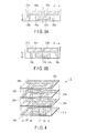
- FIGS. 3A and 3B are views showing one configuration example of a piezoelectric material forming the piezoelectric device 3.
- the piezoelectric device 3 is configured in such a manner that a plurality of piezoelectric materials 21a shown in FIG. 3A and piezoelectric materials 21b shown in FIG. 3B are alternately stacked and sintered.
- the piezoelectric material 21a is formed with three internal electrodes 23a, 25a and 27a at its surface. These internal electrodes are extended toward the same longer side (side A) of the rectangular piezoelectric material 21a. Further, the piezoelectric material 21a has exposed portions 29a, 31a and 33a to the outer periphery.
- the piezoelectric material 21b is formed with three internal electrodes 23b, 25b and 27b at its surface. These internal electrodes are extended toward the same longer side (side A) of the rectangular piezoelectric material 21b. Further, the piezoelectric material 21b has exposed portions 29b, 31b and 33b to the outer periphery.
- Internal electrodes 23a, 25a and 27a of the piezoelectric material 21a and internal electrodes 23b, 25b and 27b of the piezoelectric material 21b have the following configuration. Specifically, when a plurality of piezoelectric materials 21a and 21b is alternately stacked, the foregoing internal electrodes 23a, 25a and 27a and internal electrodes 23b, 25b and 27b are arranged so that they are overlapped corresponding to each other (see FIG. 4 described later).
- exposed portions 29a, 31a and 33a of the piezoelectric material 21a and exposed portions 29b, 31b and 33b of the piezoelectric material 21b have the following configuration. Specifically, when a plurality of piezoelectric materials 21a and 21b is alternately stacked, the foregoing exposed portions 29a, 31a and 33a and exposed portions 29b, 31b and 33b are arranged so that they are not overlapped (all exposed portions are not overlapped) (see FIG. 4 described later).
- zirconic/titanic acid lead is used as the foregoing piezoelectric materials 21a and 21b.
- the vertical thickness on the paper of piezoelectric materials 21a and 21b is set to an arbitrary range from about 10 to 200 ⁇ m.
- a conductive material having a high melting point such as sliver palladium durable to temperature used for sintering piezoelectric materials is used as the material of internal electrodes 23a, 25a and 27a and internal electrodes 23b, 25b and 27b.
- FIG. 4 is a schematic view showing a stacking example when a plurality of piezoelectric materials 21a and 21b shown in FIG. 3 is alternately stacked and sintered.
- the foregoing piezoelectric materials 21a and 21b are alternately stacked and sintered, and thereafter, exposed portions 29a are short-circuited each other to form an external electrode 41.
- exposed portions 31a, 33a, 29b, 31b and 33b are short-circuited each other to form external electrodes 43, 45, 47, 49 and 51, respectively.
- conductive materials such as silver palladium or silver having a thickness of 10 ⁇ m are used as the material for the foregoing external electrodes 41, 43, 47, 49 and 51.
- polarization is performed between the foregoing external electrodes 41 and 43, and thereby, a common area in the stacked direction, that is, internal electrodes 23a and 23b only are formed as a piezoelectric active area.
- an alternating signal is applied between external electrodes 41 and 43, and thereby, a vibration is produced in the piezoelectric device 3.
- polarization is performed between the foregoing external electrodes 45 and 47, and thereby, a common area in the stacked direction, that is, internal electrodes 27a and 27b only are formed as a piezoelectric active area. In this case, an alternating signal is applied between external electrodes 45 and 47 and thereby, a vibration is produced in the piezoelectric device 3.
- polarization is performed between the foregoing external electrodes 49 and 51 and thereby, a common area in the stacked direction, that is, internal electrodes 25a and 25b only are formed as a piezoelectric active area. In this case, an alternating signal is applied between external electrodes 49 and 51 and thereby, a vibration is produced in the piezoelectric device 3.
- the foregoing active area formed of internal electrodes 23a and 23b and the foregoing active area formed of internal electrodes 25a and 25b are used when longitudinal vibration and flexural vibration are simultaneously induced in the piezoelectric device 3 or when flexural vibration only is induced.
- the foregoing active area formed of internal electrodes 27a and 27b is used for inducing a longitudinal vibration in the piezoelectric device 3 or detecting the vibrational state of the piezoelectric device 3.
- the foregoing polarization is the option in its axis.
- the polarization axis is not the same in the piezoelectric active areas between internal electrodes 23a and 23b and between internal electrodes 25a and 25b.
- a sheet of stacked piezoelectric materials 21a and 21b is the option.
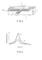
- FIG. 5 is a view showing a piezoelectric device 3 connecting a holding member 5, a drive force output member 9 and a feed member 13a.
- connection wires from several external electrodes are collected on one feed member 13a using a flexible printed board.
- the foregoing flexible printed board and the external electrode 11 are connected by means of thermal pressure using a conductive bonding agent, for example.
- the flexible printed board is relatively light; therefore, the effect of reducing a vibrational loss is great compared with the case of welding a lead wire to an external electrode.
- the extensional axis of the feed member 13 is set to an axis independent of the longitudinal and flexural vibrational axes. In this way, it is possible to reduce a vibrational loss resulting from the feed member 13 as can be seen from a graph shown in FIG. 6 .
- FIG. 6 is a graph taking vibrational amplitude of a piezoelectric device 3 as the vertical axis, and taking a vibrational frequency thereof as the horizontal axis.
- a characteristic curve 71 is a characteristic curve of an ultrasonic motor according to one embodiment.
- a characteristic curve 73 is a characteristic curve of a conventional ultrasonic motor (Namely, the extensional axis of a feed member coincides with the longitudinal vibrational or flexural vibrational axis of a piezoelectric device 3).
- the extensional axis of the feed member 13 is set to an axis independent of the longitudinal vibrational and flexural vibrational axes of a piezoelectric device 3.
- the characteristic curve 71 it is possible to achieve a preferable drive efficiency reducing a vibrational amplitude loss.
- the ultrasonic motor according to this embodiment can reduce a vibrational loss resulting from the feed member to improve a drive efficiency.
- a vibrational loss resulting from the feed member can be reduced as described above. Therefore, the feed member 13 and external electrodes 41, 43, 45, 49 and 51 are located at a position corresponding to the middle of the piezoelectric device 3. This serves to provide an ultrasonic motor having a high freedom of design without limiting located places of the feed member 13 and external electrodes 41, 43, 45, 49 and 51.
- FIG. 7 is a view showing one modification example of the structure of the ultrasonic motor shown in FIG. 1 .
- the longitudinal vibrational axis of the piezoelectric device 3 and the driving axis of the driven member 7 are the same.
- the flexural vibrational axis of the piezoelectric device 3 and the driving axis of the driven member 7 are the same.
- the following structure is employed, namely, the flexural vibrational axis of the piezoelectric device 3 and the driving axis of the driven member 7 are the same. Even if the foregoing structure is employed, the extensional axis of the feed member 13 is set to an axis different from the longitudinal and flexural vibrations as in the case of the structure shown in FIG. 1 . In this way, the same effect as obtained by the structure shown in FIG. 1 is obtained.
- the number of internal electrodes is set to three in one piezoelectric material according to the foregoing embodiment. Of course, two or four internal electrodes may be used. In also case, the configuration is performed like the ultrasonic motor according to the foregoing embodiment. Therefore, a space is effectively used to preferably make a proper design.
- the foregoing embodiment includes various inventive steps, and various inventions are made by properly combining a plurality of disclosed constituent components. For example, even if some constituent components are deleted from all constituent components, it is possible to solve the problem described in the column "Problem that the invention is to solve”. If the effect described in the column "Effect of the invention” is obtained, the configuration of deleting the constituent components is provided as the invention.
Landscapes
- General Electrical Machinery Utilizing Piezoelectricity, Electrostriction Or Magnetostriction (AREA)
Abstract
Description
- The present invention relates to an ultrasonic motor.
- Recently, a small-size, high-torque, long-stroke and high-resolution ultrasonic motor has been frequently used compared with an electromagnetic motor. For example, Jpn. Pat. Appln. KOKAI Publication No.
2005-65358 - Specifically, in order to realize high efficiency, the ultrasonic motor disclosed in the foregoing Publication No.
2005-65358 - However, the position provided with the external electrode corresponds to the middle of longitudinal vibration in a stacked piezoelectric device.
- Further, the ultrasonic motor disclosed in the foregoing Publication No.
2005-65358 2005-65358 - The present invention has been made in view of the foregoing circumstances. An object of the invention is to provide a high-efficiency ultrasonic motor, which can prevent a vibrational loss resulting from a feed member.
- In order to achieve the foregoing object, according to a first aspect of the present invention, there is provided an ultrasonic motor driving a piezoelectric device; a feed member feeding the piezoelectric device; and a driven member using an elliptical vibration synthesizing a longitudinal vibrational mode and a flexural vibrational mode as a drive force, characterized in that an extensional axis of the feed member is set to an axis different from main vibrational axes of the longitudinal vibrational mode and the flexural vibrational mode.
-
-
FIG. 1 is a view showing the structure of an ultrasonic motor according to one embodiment of the present invention; -
FIG. 2 is a view showing a model of an ultrasonic motor according to one embodiment of the present invention using an equivalent mass m related to displacement of a piezoelectric device near a drive force output member, a force F produced by a vibration of the piezoelectric device near the drive force output member, loads K and C by a feed member; -
FIG. 3A is a view showing one configuration example of a piezoelectric material forming thepiezoelectric device 3; -
FIG. 3B is a view showing one configuration example of a piezoelectric material forming thepiezoelectric device 3; -
FIG. 4 is a schematic view showing one stacked example when a plurality of piezoelectric materials shown inFIGS. 3A and 3B are and sintered; -
FIG. 5 is a view showing a piezoelectric device connecting a hold member, a drive force output member and a feed member; -
FIG. 6 is a graph taking vibrational amplitude of a piezoelectric device as the vertical axis and taking a vibrational frequency of a piezoelectric device as the horizontal axis; and -
FIG. 7 is a view showing a modification example of the structure of the ultrasonic motor shown inFIG. 1 . - An ultrasonic motor according to one embodiment of the present invention will be hereinafter described with reference to the accompanying drawings.
-
FIG. 1 is a view showing the structure of an ultrasonic motor according to one embodiment of the present invention. As seen fromFIG. 1 , the ultrasonic motor includes apiezoelectric device 3, aholding member 5 of thepiezoelectric device 3, a drivenmember 7, a driveforce output member 9, anexternal electrode 11 of thepiezoelectric device 3 and afeed member 13. In this case, the driveforce output member 9 obtains a drive force from elliptical vibration (described later) in thepiezoelectric device 3 to drive the drivenmember 7. Thefeed member 13 comprises a lead wire for feeding thepiezoelectric device 3, for example. - The
piezoelectric device 3 held by theholding member 5 contacts the drivenmember 7 to vertically apply a pressure force to the drivenmember 7 via the driveforce output member 9. - When two alternating signals having a phase difference are applied to the external electrode of the
piezoelectric device 3 via thefeed member 13, elliptical vibration synthesizing a longitudinal vibrational mode and a flexural vibrational mode is produced in thepiezoelectric device 3. - Of course, the drive
force output member 9 attached to thepiezoelectric device 3 produces the same elliptical vibration as thepiezoelectric device 3. The foregoing elliptical vibration of the driveforce output member 9 drives the drivenmember 7 contacting the driveforce output member 9 as described above. - The foregoing
external electrode 11 andfeed member 13 are essentially constituent members for driving an ultrasonic motor. However, thefeed member 13 also functions as a load, which damps the vibration of thepiezoelectric device 3. In other words, thefeed member 13 is a factor in reducing the efficiency of the ultrasonic motor in comparison with the conventional case. - Specifically, for example, if the extensional axis of the
feed member 13 coincides with the axis of longitudinal or flexural vibration of thepiezoelectric device 3, vibrational loss of the piezoelectric device remarkably appears. -
FIG. 2 is a view showing a model of the ultrasonic motor shown inFIG. 1 using an equivalent mass m related to displacement near the driveforce output member 9, a force F produced by a vibration near the driveforce output member 9, load coefficients K and C showing a load by thefeed member 13. - In this case, a motion formula of the vibrational axis near the drive
force output member 9 is expressed by the following formula.
- The foregoing load coefficients K and C are determined depending on the extensional axis, kind, size, soldering method of the feed member and a distance to the drive
force output member 9. The displacement X express displacement to the main displacement axis near the driveforce output member 9. - The foregoing force F produced by the piezoelectric effect of the
piezoelectric device 3 is constant; therefore, the foregoing (Formula 1) is expressed by the following formula.
- In this case, the extensional axis of the
feed member 13 is set independently of the vibrational axis X shown inFIG. 2 . In this way, K and C values of the foregoing (Formula 2) can be made small. Namely, the extensional axis of thefeed member 13 is set independently of the foregoing vibrational axis X without changing a design of thepiezoelectric device 3 and a method of manufacturing the same. This serves to realize a high-efficiency ultrasonic motor, which reduces vibrational loss by thefeed member 13. - The vibrational axis X of the model described referring to
FIG. 2 can be regarded as both axes of longitudinal and flexural vibration of thepiezoelectric device 3. Namely, the model described referring toFIG. 2 is a generalized model applicable to both longitudinal and flexural vibrations of thepiezoelectric device 3. - Therefore, the extensional axis of the
feed member 13 is set to the axis independent of both longitudinal and flexural vibrations of thepiezoelectric device 3. In this way, it is possible to greatly reduce a vibrational loss by thefeed member 13. Specifically, the extensional axis of thefeed member 13 is preferably set to an axis made by an angle of 90° to the axes of longitudinal and flexural vibration of thepiezoelectric device 3. - The smaller the vibrational loss by the
feed member 13 is, the larger vibrational acceleration near the driveforce output member 9 becomes. In other words, a more high-efficiency ultrasonic motor can be provided. - The detailed configuration of an ultrasonic motor according to one embodiment of the present invention will be described below with reference to
FIGS. 3 and 4 . -
FIGS. 3A and 3B are views showing one configuration example of a piezoelectric material forming thepiezoelectric device 3. According to this embodiment, thepiezoelectric device 3 is configured in such a manner that a plurality ofpiezoelectric materials 21a shown inFIG. 3A andpiezoelectric materials 21b shown inFIG. 3B are alternately stacked and sintered. - As shown in
FIG. 3A , thepiezoelectric material 21a is formed with threeinternal electrodes piezoelectric material 21a. Further, thepiezoelectric material 21a has exposedportions - Likewise, as shown in
FIG. 3B , thepiezoelectric material 21b is formed with threeinternal electrodes piezoelectric material 21b. Further, thepiezoelectric material 21b has exposedportions -
Internal electrodes piezoelectric material 21a andinternal electrodes piezoelectric material 21b have the following configuration. Specifically, when a plurality ofpiezoelectric materials internal electrodes internal electrodes FIG. 4 described later). - On the other hand, exposed
portions piezoelectric material 21a and exposedportions piezoelectric material 21b have the following configuration. Specifically, when a plurality ofpiezoelectric materials portions portions FIG. 4 described later). - For example, zirconic/titanic acid lead is used as the foregoing
piezoelectric materials piezoelectric materials - For example, a conductive material having a high melting point such as sliver palladium durable to temperature used for sintering piezoelectric materials is used as the material of
internal electrodes internal electrodes -
FIG. 4 is a schematic view showing a stacking example when a plurality ofpiezoelectric materials FIG. 3 is alternately stacked and sintered. As seen fromFIG. 4 , the foregoingpiezoelectric materials portions 29a are short-circuited each other to form anexternal electrode 41. Likewise, exposedportions external electrodes - In this case, conductive materials such as silver palladium or silver having a thickness of 10 µm are used as the material for the foregoing
external electrodes - For example, polarization is performed between the foregoing
external electrodes internal electrodes external electrodes piezoelectric device 3. - Likewise, for example, polarization is performed between the foregoing
external electrodes internal electrodes external electrodes piezoelectric device 3. Further, likewise, for example, polarization is performed between the foregoingexternal electrodes internal electrodes external electrodes piezoelectric device 3. - The foregoing active area formed of
internal electrodes internal electrodes piezoelectric device 3 or when flexural vibration only is induced. On the other hand, the foregoing active area formed ofinternal electrodes piezoelectric device 3 or detecting the vibrational state of thepiezoelectric device 3. - The foregoing polarization is the option in its axis. In other words, in the same piezoelectric material, the polarization axis is not the same in the piezoelectric active areas between
internal electrodes internal electrodes piezoelectric materials -
FIG. 5 is a view showing apiezoelectric device 3 connecting a holdingmember 5, a driveforce output member 9 and afeed member 13a. - As can be seen from the
feed member 13a illustrated inFIG. 5 , for example, connection wires from several external electrodes are collected on onefeed member 13a using a flexible printed board. In this way, the number of members is reduced, and the connection process of thefeed member 13a is simplified. The foregoing flexible printed board and theexternal electrode 11 are connected by means of thermal pressure using a conductive bonding agent, for example. The flexible printed board is relatively light; therefore, the effect of reducing a vibrational loss is great compared with the case of welding a lead wire to an external electrode. - As described above, according to this embodiment, it is possible to realize a high-efficiency ultrasonic motor, which prevents a vibrational loss resulting from a fee member.
- Specifically, the extensional axis of the
feed member 13 is set to an axis independent of the longitudinal and flexural vibrational axes. In this way, it is possible to reduce a vibrational loss resulting from thefeed member 13 as can be seen from a graph shown inFIG. 6 . -
FIG. 6 is a graph taking vibrational amplitude of apiezoelectric device 3 as the vertical axis, and taking a vibrational frequency thereof as the horizontal axis. In the graph ofFIG. 6 , acharacteristic curve 71 is a characteristic curve of an ultrasonic motor according to one embodiment. On the other hand, acharacteristic curve 73 is a characteristic curve of a conventional ultrasonic motor (Namely, the extensional axis of a feed member coincides with the longitudinal vibrational or flexural vibrational axis of a piezoelectric device 3). - Specifically, in the ultrasonic motor according to one embodiment, the extensional axis of the
feed member 13 is set to an axis independent of the longitudinal vibrational and flexural vibrational axes of apiezoelectric device 3. In this case, as seen from thecharacteristic curve 71, it is possible to achieve a preferable drive efficiency reducing a vibrational amplitude loss. - In this way, the ultrasonic motor according to this embodiment can reduce a vibrational loss resulting from the feed member to improve a drive efficiency.
- According to one embodiment, a vibrational loss resulting from the feed member can be reduced as described above. Therefore, the
feed member 13 andexternal electrodes piezoelectric device 3. This serves to provide an ultrasonic motor having a high freedom of design without limiting located places of thefeed member 13 andexternal electrodes - The present invention has been described based on the foregoing one embodiment. However, the present invention is not limited to the foregoing embodiment. Off course, various modifications and applications are possible within the scope of the invention.
-
FIG. 7 is a view showing one modification example of the structure of the ultrasonic motor shown inFIG. 1 . - As described above, according to the example shown in
FIG. 1 , the longitudinal vibrational axis of thepiezoelectric device 3 and the driving axis of the drivenmember 7 are the same. On the other hand, according to the example shown inFIG. 7 , the flexural vibrational axis of thepiezoelectric device 3 and the driving axis of the drivenmember 7 are the same. - As depicted in
FIG. 7 , the following structure is employed, namely, the flexural vibrational axis of thepiezoelectric device 3 and the driving axis of the drivenmember 7 are the same. Even if the foregoing structure is employed, the extensional axis of thefeed member 13 is set to an axis different from the longitudinal and flexural vibrations as in the case of the structure shown inFIG. 1 . In this way, the same effect as obtained by the structure shown inFIG. 1 is obtained. - The number of internal electrodes is set to three in one piezoelectric material according to the foregoing embodiment. Of course, two or four internal electrodes may be used. In also case, the configuration is performed like the ultrasonic motor according to the foregoing embodiment. Therefore, a space is effectively used to preferably make a proper design.
- The foregoing embodiment includes various inventive steps, and various inventions are made by properly combining a plurality of disclosed constituent components. For example, even if some constituent components are deleted from all constituent components, it is possible to solve the problem described in the column "Problem that the invention is to solve". If the effect described in the column "Effect of the invention" is obtained, the configuration of deleting the constituent components is provided as the invention.
Claims (10)
- An ultrasonic motor driving
a piezoelectric device (3);
a feed member (13, 13a) feeding the piezoelectric device (3); and
a driven member (7) using an elliptical vibration synthesizing a longitudinal vibrational mode and a flexural vibrational mode as a drive force,
characterized in that
an extensional axis of the feed member (13, 13a) is set to an axis different from main vibrational axes of the longitudinal vibrational mode and the flexural vibrational mode. - The ultrasonic motor according to claim 1, characterized in that the piezoelectric device (3) is configured in such a manner that rectangular piezoelectric materials (21a, 21b) and a plurality of internal electrodes (23a, 25a, 27a, 23b, 25b, 27b) formed on the piezoelectric materials (21a, 21b) are alternately stacked.
- The ultrasonic motor according to claim 2, characterized in that the internal electrodes (23a, 25a, 27a, 23b, 25b, 27b) are extended toward the same one side of the piezoelectric materials (21a, 21b), and electrically connected to the feed member (13, 13a) via exposed portions (29a, 31a, 33a, 29b, 31b, 33b) at the outer periphery of the piezoelectric device (3) and external electrodes (41, 43, 45, 47, 49, 51).
- The ultrasonic motor according to claim 3, characterized in that the same one side is a longer side of the rectangular piezoelectric materials (21a, 21b).
- The ultrasonic motor according to claim 3, characterized by further including:a drive force output member (9) driving the driven member (7) using a drive force obtained from an elliptical vibration of the piezoelectric device (3),the drive force output member (9) being located at a surface of the piezoelectric device (3), which surface is opposite to a surface formed with the external electrodes (41, 43, 45, 47, 49, 51).
- The ultrasonic motor according to claim 3, characterized by further including:a holding member (5) for holding the piezoelectric device (3),the holding member (5) being located on the same surface as a surface formed with the external electrodes (41, 43, 45, 47, 49, 51).
- The ultrasonic motor according to claim 1, characterized in that the feed member (13, 13a) comprises a flexible printed board.
- The ultrasonic motor according to claim 7, characterized in that the flexible printed board and the piezoelectric device (3) are connected by means of a conductive bonding agent.
- The ultrasonic motor according to claim 1, characterized in that the driven axis of the driven member coincides with the vibrational axis of the longitudinal vibrational mode.
- The ultrasonic motor according to claim 1, characterized in that the driven axis of the driven member coincides with the vibrational axis of the flexural vibrational mode.
Applications Claiming Priority (2)
| Application Number | Priority Date | Filing Date | Title |
|---|---|---|---|
| JP2007169517 | 2007-06-27 | ||
| PCT/JP2008/061258 WO2009001753A1 (en) | 2007-06-27 | 2008-06-19 | Ultrasonic motor |
Publications (2)
| Publication Number | Publication Date |
|---|---|
| EP2166661A1 true EP2166661A1 (en) | 2010-03-24 |
| EP2166661A4 EP2166661A4 (en) | 2011-12-28 |
Family
ID=40185571
Family Applications (1)
| Application Number | Title | Priority Date | Filing Date |
|---|---|---|---|
| EP08777414A Withdrawn EP2166661A4 (en) | 2007-06-27 | 2008-06-19 | Ultrasonic motor |
Country Status (5)
| Country | Link |
|---|---|
| US (1) | US7923900B2 (en) |
| EP (1) | EP2166661A4 (en) |
| JP (1) | JP5551434B2 (en) |
| CN (1) | CN101689817B (en) |
| WO (1) | WO2009001753A1 (en) |
Families Citing this family (2)
| Publication number | Priority date | Publication date | Assignee | Title |
|---|---|---|---|---|
| CN102751900B (en) * | 2012-07-17 | 2015-08-12 | 浙江大学 | Two-freedom supersonic motor |
| JP6602054B2 (en) * | 2015-05-29 | 2019-11-06 | キヤノン株式会社 | Piezoelectric body, vibrator, and vibration wave motor |
Family Cites Families (12)
| Publication number | Priority date | Publication date | Assignee | Title |
|---|---|---|---|---|
| JPS4942435B1 (en) * | 1970-08-28 | 1974-11-14 | ||
| EP0198183B1 (en) * | 1985-04-19 | 1992-08-12 | Hitachi Maxell Ltd. | Ultrasonic motor |
| JPH09135586A (en) * | 1995-11-08 | 1997-05-20 | Nikon Corp | Vibration actuator |
| JPH09233868A (en) * | 1996-02-23 | 1997-09-05 | Canon Inc | Vibration device |
| JPH10341580A (en) * | 1997-06-10 | 1998-12-22 | Nikon Corp | Oscillatory actuator |
| JP4459317B2 (en) * | 1998-08-07 | 2010-04-28 | セイコーインスツル株式会社 | Ultrasonic motor and electronic equipment with ultrasonic motor |
| JP3041608B2 (en) * | 1998-09-18 | 2000-05-15 | セイコーインスツルメンツ株式会社 | Bimorph actuator |
| JP4641709B2 (en) | 2003-08-12 | 2011-03-02 | セイコーインスツル株式会社 | Ultrasonic motor using laminated piezoelectric vibrator and electronic device using the same |
| JP2005333749A (en) * | 2004-05-20 | 2005-12-02 | Olympus Corp | Ultrasonic vibrator and ultrasonic motor using the same |
| JP4185486B2 (en) * | 2004-12-27 | 2008-11-26 | Tdk株式会社 | Multilayer piezoelectric element |
| JP4794897B2 (en) * | 2005-04-26 | 2011-10-19 | オリンパス株式会社 | Ultrasonic motor |
| US20100019621A1 (en) * | 2008-07-14 | 2010-01-28 | Olympus Corporation | Ultrasonic motor and ultrasonic motor apparatus retaining the same |
-
2008
- 2008-06-19 JP JP2009520538A patent/JP5551434B2/en not_active Expired - Fee Related
- 2008-06-19 WO PCT/JP2008/061258 patent/WO2009001753A1/en not_active Ceased
- 2008-06-19 EP EP08777414A patent/EP2166661A4/en not_active Withdrawn
- 2008-06-19 CN CN200880021859.3A patent/CN101689817B/en not_active Expired - Fee Related
-
2009
- 2009-12-17 US US12/640,392 patent/US7923900B2/en not_active Expired - Fee Related
Also Published As
| Publication number | Publication date |
|---|---|
| WO2009001753A1 (en) | 2008-12-31 |
| JPWO2009001753A1 (en) | 2010-08-26 |
| CN101689817A (en) | 2010-03-31 |
| US7923900B2 (en) | 2011-04-12 |
| JP5551434B2 (en) | 2014-07-16 |
| CN101689817B (en) | 2012-09-05 |
| EP2166661A4 (en) | 2011-12-28 |
| US20100096948A1 (en) | 2010-04-22 |
Similar Documents
| Publication | Publication Date | Title |
|---|---|---|
| EP1017116B1 (en) | Piezoelectric/electrostrictive device and method of fabricating the same | |
| US7501745B2 (en) | Piezoelectric vibrator | |
| US6455984B1 (en) | Piezoelectric/electrostrictive device and method of manufacturing same | |
| JP2019530111A (en) | Device for generating tactile feedback | |
| WO2013114857A1 (en) | Piezoelectric actuator device and method for manufacturing same | |
| CN104297918A (en) | Mirror drive device and driving method thereof | |
| WO2014050586A1 (en) | Mirror driving device and driving method for same | |
| JP2004104984A (en) | Ultrasonic linear motor | |
| US20100213792A1 (en) | Multilayered piezoelectric element and ultrasonic motor | |
| CN104297919A (en) | Mirror drive device and driving method thereof | |
| US10682768B2 (en) | Force detection sensor, force sensor, torque sensor, and robot | |
| WO2012073741A1 (en) | Piezoelectric power generating device | |
| JP5294143B2 (en) | Angular velocity sensor element | |
| WO2018021166A1 (en) | Angular velocity sensor, sensor element, and multi-axis angular velocity sensor | |
| EP2166661A1 (en) | Ultrasonic motor | |
| EP2555175A1 (en) | Transducer module | |
| JP2013135596A (en) | Vibration power generating element | |
| JPWO2006070595A1 (en) | Piezoelectric ceramic actuator and portable device | |
| JP2008191034A (en) | Compound sensor | |
| JP5089039B2 (en) | Piezoelectric element, piezoelectric transducer and electronic device using them | |
| JP4818858B2 (en) | Ultrasonic motor element | |
| JP4818853B2 (en) | Ultrasonic motor element | |
| JP5329912B2 (en) | Ultrasonic motor | |
| JP5327579B2 (en) | Angular velocity sensor element | |
| JP5235361B2 (en) | Sensor |
Legal Events
| Date | Code | Title | Description |
|---|---|---|---|
| PUAI | Public reference made under article 153(3) epc to a published international application that has entered the european phase |
Free format text: ORIGINAL CODE: 0009012 |
|
| 17P | Request for examination filed |
Effective date: 20091217 |
|
| AK | Designated contracting states |
Kind code of ref document: A1 Designated state(s): AT BE BG CH CY CZ DE DK EE ES FI FR GB GR HR HU IE IS IT LI LT LU LV MC MT NL NO PL PT RO SE SI SK TR |
|
| AX | Request for extension of the european patent |
Extension state: AL BA MK RS |
|
| RIN1 | Information on inventor provided before grant (corrected) |
Inventor name: SIMIZU, MORIMITI Inventor name: FUNAKUBO, TOMOKI Inventor name: SAKANO, HIROMICHI Inventor name: SAKAI, NAGAHIDE |
|
| RIN1 | Information on inventor provided before grant (corrected) |
Inventor name: SIMIZU, MORIMITI Inventor name: FUNAKUBO, TOMOKI Inventor name: SAKANO, HIROMICHI Inventor name: SAKAI, NAGAHIDE |
|
| DAX | Request for extension of the european patent (deleted) | ||
| A4 | Supplementary search report drawn up and despatched |
Effective date: 20111130 |
|
| RIC1 | Information provided on ipc code assigned before grant |
Ipc: H01L 41/09 20060101ALI20111124BHEP Ipc: H01L 41/047 20060101ALI20111124BHEP Ipc: H02N 2/00 20060101AFI20111124BHEP |
|
| 17Q | First examination report despatched |
Effective date: 20120801 |
|
| STAA | Information on the status of an ep patent application or granted ep patent |
Free format text: STATUS: THE APPLICATION HAS BEEN WITHDRAWN |
|
| 18W | Application withdrawn |
Effective date: 20130715 |