EP2166429A1 - Electronic device and heat dissipation unit thereof - Google Patents
Electronic device and heat dissipation unit thereof Download PDFInfo
- Publication number
- EP2166429A1 EP2166429A1 EP08164633A EP08164633A EP2166429A1 EP 2166429 A1 EP2166429 A1 EP 2166429A1 EP 08164633 A EP08164633 A EP 08164633A EP 08164633 A EP08164633 A EP 08164633A EP 2166429 A1 EP2166429 A1 EP 2166429A1
- Authority
- EP
- European Patent Office
- Prior art keywords
- heat
- heat dissipation
- housing
- electronic device
- disposed
- Prior art date
- Legal status (The legal status is an assumption and is not a legal conclusion. Google has not performed a legal analysis and makes no representation as to the accuracy of the status listed.)
- Granted
Links
Images

Classifications
-
- G—PHYSICS
- G06—COMPUTING OR CALCULATING; COUNTING
- G06F—ELECTRIC DIGITAL DATA PROCESSING
- G06F1/00—Details not covered by groups G06F3/00 - G06F13/00 and G06F21/00
- G06F1/16—Constructional details or arrangements
- G06F1/20—Cooling means
Definitions
- the present invention relates to an electronic device, and in particular, to an electronic device comprising additional heat dissipation ability.
- heat dissipation systems are provided to dissipate heat produced by the heat sources within the electronic devices.
- the heat dissipation system utilizes a heatsink to abut a heat source directly, thus transmitting heat from the heat source to the heatsink.
- air convection is conducted within the electronic device by using a system fan, exhausting heat accumulated in the heatsink.
- the electronic device includes a housing, a circuit board, a heat source, a heat dissipation system and a heat dissipation unit.
- the circuit board is disposed in the housing and the heat source is disposed on the circuit board.
- the heat dissipation system abuts the heat source, and the heat dissipation unit, disposed on the housing, abuts the heat dissipation system, wherein a portion of the heat dissipation unit is exposed outside of the housing.
- the invention further provides a heat dissipation unit.
- the heat dissipation unit includes a connecting portion, a heat exchanger, and a heat pipe.
- the connecting portion disposed in the housing, abuts the heat dissipation system.
- the heat exchanger is disposed in the housing, and a portion of the heat exchanger is exposed outside of the housing.
- the heat pipe connects the connecting portion with the heat exchanger.
- Fig. 1 is a schematic view of an electronic device of the invention
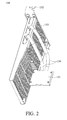
- Fig. 2 is a schematic view of a heat dissipation unit of the invention
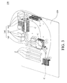
- Fig. 3 is a schematic view of the electronic device from another perspective, before application of the heat dissipation unit.
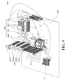
- Fig. 4 is a schematic view of the electronic device from another perspective, after application of the heat dissipation unit.
- the electronic device 100 comprises a housing 110, a circuit board 120, a heat dissipation system 140, a heat dissipation unit 150 and a plurality of heat sources C.
- the heat dissipation unit 150 is a supporting heat dissipation mechanism to enhance the heat dissipation efficiency of the overall system.
- the circuit board 120 is disposed in the housing 110.
- the plurality of heat sources C are distributed on the circuit board 120. Through application of the heat dissipation system 140, heat generated by the heat sources C is therefore dissipated.
- the heat dissipation system 140 comprises a plurality of heatsinks 141 and a plurality of first heat pipes 140.
- the number of heatsinks 141 is selected according to the number of heat sources C.
- the electronic device 100 comprises four heat sources C four heatsinks 141, but it is not limited thereto.
- the heatsinks 141 abut the heat sources C, respectively, such that heat from the heat sources C is able to transmit to the heatsinks 141. Additionally, every heatsink 141 is interconnected by one or two first heat pipes 141, allowing every heatsink 141 to achieve an average temperature. As a result, none of the heat sources C would be burned due to overheating. Next, a system fan is utilized for air convection within the housing 100, and further exhaust heat.
- the heat dissipation system 140 further comprises a water block 144 and a water-cooling system (not shown), as shown in Fig. 4 .
- the water block 144 is disposed on any of the heatsinks 141.
- the water-cooling system is disposed outside of the housing 110, communicated with the water block 144.
- the heat accumulated in the heatsinks 141 is able to be transmitted to the water-cooling system through the circulating cooling fluid, and then dissipated.
- the housing 110 has an aperture O.
- the heat dissipation unit 150 disposed in the housing 110, is adjacent to a PCI-E slot P, and a portion of the heat dissipation unit 150 is exposed outside of the housing 110.
- the heat dissipation unit 150 comprises a connecting portion 151, a fastening portion 152, a heat exchanger and two second heat pipes 154.
- the connecting portion 151 connects with the heat dissipation system 140.
- the second heat pipes 154 function to connect the connecting portion 15 and the heat exchanger.
- the fastening portion 152 is fixed on the periphery of the aperture O of the housing 110.
- the heat exchanger connects with the fastening portion 152, such that the heat exchanger is also fixed on the housing 110 by the fastening portion 152, and is therefore mounted in the housing 110.
- the heat exchanger comprises a plurality of stacked fins 153, and each of the fins 153 comprises an end portion 153E (as shown in Fig. 1 ). When the heat exchanger is fixed on the housing 110 by the fastening portion 152, the end portion 153E of each fin 153 is exposed outside of the housing 110.
- the heat dissipation unit 150 is disposed in the spare space adjacent to the PCI-E slot P, utilizing the empty space around the PCI-E slot P. Therefore, heat dissipation efficiency is significantly enhanced without increasing the overall volume of the electronic device 100.
- the embodiment is not limited thereto.
- the heat dissipation unit 150 can be disposed at any position within the housing 110, and only the alteration of the length of the second heat pips 154 is required to connect the connecting portion 151 with the heat dissipation system 140.
- Figs. 3 and 4 depict the housing 110 is excluded to clearly show the interior of the electronic device 100.
- Fig. 3 depicts the electronic device 100 before application of the heat dissipation unit 150
- Fig. 4 depicts the electronic device 100 after application of the heat dissipation unit 150.
- the heat dissipation system 140 further comprises a corresponding connecting portion 143 for connecting the heat dissipation unit 150 with the heat dissipation system 140.
- the corresponding connecting portion 143 is disposed on any of the heatsinks 141 to abut the connecting portion 151 of the heat dissipation unit 150.
- the corresponding connecting portion 143 comprises two grooves to accommodate the two second heat pipes 154.
- the corresponding portion 143 is disposed on one of the heatsinks 141, but it is not limited thereto.
- the corresponding connecting portion 143 can also be disposed on the first heat pipe 142, as long as the conduction of heat from in the heat dissipation system 140 to the heat dissipation unit 150 is successfully achieved.
- heat is also dissipated through the heat dissipation unit 150 connected to the heat dissipation system 140 to speed up heat dissipation efficiency. Because a portion of the heat dissipation unit 150 is exposed outside of the housing 110, directly exposed to the atmosphere, heat accumulated within the heat dissipation system 140 is efficiently transmitted to the exterior of the housing 110. Moreover, the heat dissipation unit 150 is disposed in the unused space within the housing 110, such that reconfiguration of the components within the housing 110 is not required, and the overall size of the electronic device 100 can be retained.
Landscapes
- Engineering & Computer Science (AREA)
- Theoretical Computer Science (AREA)
- Human Computer Interaction (AREA)
- Physics & Mathematics (AREA)
- General Engineering & Computer Science (AREA)
- General Physics & Mathematics (AREA)
- Cooling Or The Like Of Electrical Apparatus (AREA)
Abstract
Description
- The present invention relates to an electronic device, and in particular, to an electronic device comprising additional heat dissipation ability.
- In conventional electronic devices, heat dissipation systems are provided to dissipate heat produced by the heat sources within the electronic devices. The heat dissipation system utilizes a heatsink to abut a heat source directly, thus transmitting heat from the heat source to the heatsink. Next, air convection is conducted within the electronic device by using a system fan, exhausting heat accumulated in the heatsink.
- However, with continued technological development, significant heat is generated by electronic devices, due to increased performance, thus, decreasing efficiency of the conventional heat dissipation system. In other words, new electronic devices must be assembled with more powerful heat dissipation mechanisms, to efficiently dissipate heat.
- Accordingly, an electronic device is provided. The electronic device includes a housing, a circuit board, a heat source, a heat dissipation system and a heat dissipation unit. The circuit board is disposed in the housing and the heat source is disposed on the circuit board. The heat dissipation system abuts the heat source, and the heat dissipation unit, disposed on the housing, abuts the heat dissipation system, wherein a portion of the heat dissipation unit is exposed outside of the housing.
- The invention further provides a heat dissipation unit. The heat dissipation unit includes a connecting portion, a heat exchanger, and a heat pipe. The connecting portion, disposed in the housing, abuts the heat dissipation system. The heat exchanger is disposed in the housing, and a portion of the heat exchanger is exposed outside of the housing. The heat pipe connects the connecting portion with the heat exchanger.
- The present invention can be more fully understood by reading the subsequent detailed description and examples with references made to the accompanying drawings, wherein:
-
Fig. 1 is a schematic view of an electronic device of the invention; -
Fig. 2 is a schematic view of a heat dissipation unit of the invention; -
Fig. 3 is a schematic view of the electronic device from another perspective, before application of the heat dissipation unit; and -
Fig. 4 is a schematic view of the electronic device from another perspective, after application of the heat dissipation unit. - Referring to
Fig. 1 , theelectronic device 100 comprises ahousing 110, acircuit board 120, aheat dissipation system 140, aheat dissipation unit 150 and a plurality of heat sources C. In particular, theheat dissipation unit 150 is a supporting heat dissipation mechanism to enhance the heat dissipation efficiency of the overall system. - The
circuit board 120 is disposed in thehousing 110. The plurality of heat sources C are distributed on thecircuit board 120. Through application of theheat dissipation system 140, heat generated by the heat sources C is therefore dissipated. Theheat dissipation system 140 comprises a plurality ofheatsinks 141 and a plurality offirst heat pipes 140. The number ofheatsinks 141 is selected according to the number of heat sources C. In the embodiment, theelectronic device 100 comprises four heat sources C fourheatsinks 141, but it is not limited thereto. - The
heatsinks 141 abut the heat sources C, respectively, such that heat from the heat sources C is able to transmit to theheatsinks 141. Additionally, everyheatsink 141 is interconnected by one or twofirst heat pipes 141, allowing everyheatsink 141 to achieve an average temperature. As a result, none of the heat sources C would be burned due to overheating. Next, a system fan is utilized for air convection within thehousing 100, and further exhaust heat. - In addition to generating air convection to dissipate heat, the
heat dissipation system 140 further comprises awater block 144 and a water-cooling system (not shown), as shown inFig. 4 . Thewater block 144 is disposed on any of theheatsinks 141. The water-cooling system is disposed outside of thehousing 110, communicated with thewater block 144. The heat accumulated in theheatsinks 141 is able to be transmitted to the water-cooling system through the circulating cooling fluid, and then dissipated. - Referring to
Figs. 1 and2 , thehousing 110 has an aperture O. Theheat dissipation unit 150, disposed in thehousing 110, is adjacent to a PCI-E slot P, and a portion of theheat dissipation unit 150 is exposed outside of thehousing 110. Theheat dissipation unit 150 comprises a connectingportion 151, afastening portion 152, a heat exchanger and twosecond heat pipes 154. - The connecting
portion 151 connects with theheat dissipation system 140. Thesecond heat pipes 154 function to connect the connecting portion 15 and the heat exchanger. Thefastening portion 152 is fixed on the periphery of the aperture O of thehousing 110. The heat exchanger connects with thefastening portion 152, such that the heat exchanger is also fixed on thehousing 110 by thefastening portion 152, and is therefore mounted in thehousing 110. Additionally, the heat exchanger comprises a plurality of stackedfins 153, and each of thefins 153 comprises anend portion 153E (as shown inFig. 1 ). When the heat exchanger is fixed on thehousing 110 by thefastening portion 152, theend portion 153E of eachfin 153 is exposed outside of thehousing 110. - It should be noted that in the embodiment the
heat dissipation unit 150 is disposed in the spare space adjacent to the PCI-E slot P, utilizing the empty space around the PCI-E slot P. Therefore, heat dissipation efficiency is significantly enhanced without increasing the overall volume of theelectronic device 100. However, the embodiment is not limited thereto. Theheat dissipation unit 150 can be disposed at any position within thehousing 110, and only the alteration of the length of thesecond heat pips 154 is required to connect the connectingportion 151 with theheat dissipation system 140. - As shown in
Figs. 3 and4 , thehousing 110 is excluded to clearly show the interior of theelectronic device 100.Fig. 3 depicts theelectronic device 100 before application of theheat dissipation unit 150, andFig. 4 depicts theelectronic device 100 after application of theheat dissipation unit 150. - Referring to
Fig. 3 , theheat dissipation system 140 further comprises a corresponding connectingportion 143 for connecting theheat dissipation unit 150 with theheat dissipation system 140. The corresponding connectingportion 143 is disposed on any of theheatsinks 141 to abut the connectingportion 151 of theheat dissipation unit 150. The corresponding connectingportion 143 comprises two grooves to accommodate the twosecond heat pipes 154. - It should be noted that in the embodiment the
corresponding portion 143 is disposed on one of theheatsinks 141, but it is not limited thereto. The corresponding connectingportion 143 can also be disposed on thefirst heat pipe 142, as long as the conduction of heat from in theheat dissipation system 140 to theheat dissipation unit 150 is successfully achieved. - Referring to
Fig. 4 , when the connectingportion 151 is assembled to the corresponding connectingportion 143, thesecond heat pipes 154 are clamped therebetween. Thus, heat accumulated in theheat dissipation system 140 is transmitted to the heat exchanger through the connectingportion 151 and thesecond heat pipes 154, and is then exhausted to the exterior through the exposedend portions 153E of thefins 153, increasing overall heat dissipation efficiency. - For the
electronic device 100 of the invention, in addition to heat being dissipated through theheat dissipation system 140, heat is also dissipated through theheat dissipation unit 150 connected to theheat dissipation system 140 to speed up heat dissipation efficiency. Because a portion of theheat dissipation unit 150 is exposed outside of thehousing 110, directly exposed to the atmosphere, heat accumulated within theheat dissipation system 140 is efficiently transmitted to the exterior of thehousing 110. Moreover, theheat dissipation unit 150 is disposed in the unused space within thehousing 110, such that reconfiguration of the components within thehousing 110 is not required, and the overall size of theelectronic device 100 can be retained. - While the present invention has been described by way of example and in terms of preferred embodiment, it is to be understood that the present invention is not limited thereto. To the contrary, it is intended to cover various modifications and similar arrangements (as would be apparent to those skilled in the art). Therefore, the scope of the appended claims should be accorded the broadest interpretation so as to encompass all such modifications and similar arrangements.
Claims (13)
- An electronic device, comprising
a housing;
a circuit board disposed in the housing;
a heat source disposed on the circuit board;
a heat dissipation system abutting the heat source; and
a heat dissipation unit disposed on the housing and abutting the heat dissipation system,
wherein a portion of the heat dissipation unit is exposed outside of the housing. - The electronic device as claimed in claim 1, wherein the amount of the heat sources are plural, and the heat dissipation system comprises a plurality of heatsinks abutting the heat sources, respectively.
- The electronic device as claimed in claim 2, wherein the heat dissipation system comprises a plurality of first heat pipes connecting with the heat sinks, respectively.
- The electronic device as claimed in claim 1, wherein the heat dissipation unit comprises:a connecting portion abutting the heat dissipation system;a fastening portion fixed on the housing;a heat exchanger connected to the fastening portion; anda second heat pipe connecting the connecting portion with the heat exchanger.
- The electronic device as claimed in claims 4, wherein the heat exchanger comprises a plurality of fins.
- The electronic device as claimed in claim 5, wherein the housing has an aperture, and end portions of the fins are exposed outside of the housing through the aperture.
- The electronic device as claimed in claims 6, wherein the fourth coil is a self-adhesive coil or a coil wound on the winding portion.
- The electronic device as claimed in claims 4, wherein the heat dissipation system comprises a corresponding connecting portion abutting the connecting portion of the heat dissipation unit.
- The electronic device as claimed in claim 1, further comprising a PCI-E slot disposed on the circuit board, wherein the heat dissipation unit is disposed adjacent to the PCI-E slot.
- A heat dissipation unit, disposed in an electronic device having a heat dissipation system and a housing, comprising
a connecting portion disposed in the housing and abutting the heat dissipation system;
a heat exchanger disposed in the housing, and a portion of the heat exchanger being exposed outside of the housing;
a pipe connecting the connecting portion with the heat pipe. - The electronic device as claimed in claim 10, wherein the heat exchanger comprises a plurality of fins.
- The electronic device as claimed in claim 10, wherein ends of the fins are exposed outside of the housing.
- The electronic device as claimed in claim 10, further comprising a fastening portion fixed on the housing and connecting to the heat exchanger.
Priority Applications (1)
| Application Number | Priority Date | Filing Date | Title |
|---|---|---|---|
| EP08164633.3A EP2166429B1 (en) | 2008-09-18 | 2008-09-18 | Electronic device and heat dissipation unit thereof |
Applications Claiming Priority (1)
| Application Number | Priority Date | Filing Date | Title |
|---|---|---|---|
| EP08164633.3A EP2166429B1 (en) | 2008-09-18 | 2008-09-18 | Electronic device and heat dissipation unit thereof |
Publications (2)
| Publication Number | Publication Date |
|---|---|
| EP2166429A1 true EP2166429A1 (en) | 2010-03-24 |
| EP2166429B1 EP2166429B1 (en) | 2019-07-03 |
Family
ID=40280725
Family Applications (1)
| Application Number | Title | Priority Date | Filing Date |
|---|---|---|---|
| EP08164633.3A Not-in-force EP2166429B1 (en) | 2008-09-18 | 2008-09-18 | Electronic device and heat dissipation unit thereof |
Country Status (1)
| Country | Link |
|---|---|
| EP (1) | EP2166429B1 (en) |
Citations (2)
| Publication number | Priority date | Publication date | Assignee | Title |
|---|---|---|---|---|
| US20060139880A1 (en) * | 2004-12-27 | 2006-06-29 | Alan Tate | Integrated circuit cooling system including heat pipes and external heat sink |
| US20080218963A1 (en) * | 2007-03-05 | 2008-09-11 | Dfi, Inc. | Desktop personal computer and thermal module thereof |
Family Cites Families (1)
| Publication number | Priority date | Publication date | Assignee | Title |
|---|---|---|---|---|
| CN101257781A (en) * | 2007-03-01 | 2008-09-03 | 鸿富锦精密工业(深圳)有限公司 | Electronic equipment and radiators |
-
2008
- 2008-09-18 EP EP08164633.3A patent/EP2166429B1/en not_active Not-in-force
Patent Citations (2)
| Publication number | Priority date | Publication date | Assignee | Title |
|---|---|---|---|---|
| US20060139880A1 (en) * | 2004-12-27 | 2006-06-29 | Alan Tate | Integrated circuit cooling system including heat pipes and external heat sink |
| US20080218963A1 (en) * | 2007-03-05 | 2008-09-11 | Dfi, Inc. | Desktop personal computer and thermal module thereof |
Also Published As
| Publication number | Publication date |
|---|---|
| EP2166429B1 (en) | 2019-07-03 |
Similar Documents
| Publication | Publication Date | Title |
|---|---|---|
| US7613001B1 (en) | Heat dissipation device with heat pipe | |
| JP3680018B2 (en) | Multiple heat dissipation module | |
| US7800906B2 (en) | Electronic device and heat dissipation unit thereof | |
| US8630090B2 (en) | Heat dissipation device for power conversion module | |
| US8462504B2 (en) | Air-cooled heat exchanger and electronic device with same | |
| US20070139887A1 (en) | Portable projector using an LED and related heat dissipating system | |
| US6964295B1 (en) | Heat dissipation device | |
| US20140202666A1 (en) | Thermal module | |
| US20070175610A1 (en) | Heat dissipating device | |
| JP2007288061A (en) | Electronic equipment | |
| JP7139684B2 (en) | Cooling equipment and electronic equipment | |
| CN102065667A (en) | Electronic device and heat radiating device thereof | |
| US20080212285A1 (en) | Electronic equipment and heat dissipating device in the electronic equipment | |
| US7688590B2 (en) | Thermal module and electronic apparatus using the same | |
| US7447027B2 (en) | Hybrid heat dissipation device | |
| US20080169089A1 (en) | Heat sink assembly | |
| US20120073794A1 (en) | Heat dissipation device with multiple heat conducting pipes | |
| US20060203451A1 (en) | Heat dissipation apparatus with second degree curve shape heat pipe | |
| US20220071028A1 (en) | Server device | |
| CN107636562B (en) | Forced and natural convection liquid cooling device for personal computer | |
| US7365978B2 (en) | Heat dissipating device | |
| EP2166429B1 (en) | Electronic device and heat dissipation unit thereof | |
| US20080030949A1 (en) | Fluid-providing module and electronic device using the same | |
| WO2017187898A1 (en) | Heat sink and housing | |
| JP5897478B2 (en) | Electronic equipment enclosure |
Legal Events
| Date | Code | Title | Description |
|---|---|---|---|
| PUAI | Public reference made under article 153(3) epc to a published international application that has entered the european phase |
Free format text: ORIGINAL CODE: 0009012 |
|
| 17P | Request for examination filed |
Effective date: 20090620 |
|
| AK | Designated contracting states |
Kind code of ref document: A1 Designated state(s): AT BE BG CH CY CZ DE DK EE ES FI FR GB GR HR HU IE IS IT LI LT LU LV MC MT NL NO PL PT RO SE SI SK TR |
|
| AX | Request for extension of the european patent |
Extension state: AL BA MK RS |
|
| AKX | Designation fees paid |
Designated state(s): DE FR GB |
|
| RAP1 | Party data changed (applicant data changed or rights of an application transferred) |
Owner name: GIGA-BYTE TECHNOLOGY CO., LTD. |
|
| 17Q | First examination report despatched |
Effective date: 20160615 |
|
| GRAJ | Information related to disapproval of communication of intention to grant by the applicant or resumption of examination proceedings by the epo deleted |
Free format text: ORIGINAL CODE: EPIDOSDIGR1 |
|
| STAA | Information on the status of an ep patent application or granted ep patent |
Free format text: STATUS: GRANT OF PATENT IS INTENDED |
|
| GRAP | Despatch of communication of intention to grant a patent |
Free format text: ORIGINAL CODE: EPIDOSNIGR1 |
|
| INTG | Intention to grant announced |
Effective date: 20190207 |
|
| GRAS | Grant fee paid |
Free format text: ORIGINAL CODE: EPIDOSNIGR3 |
|
| GRAA | (expected) grant |
Free format text: ORIGINAL CODE: 0009210 |
|
| STAA | Information on the status of an ep patent application or granted ep patent |
Free format text: STATUS: THE PATENT HAS BEEN GRANTED |
|
| AK | Designated contracting states |
Kind code of ref document: B1 Designated state(s): DE FR GB |
|
| REG | Reference to a national code |
Ref country code: GB Ref legal event code: FG4D |
|
| REG | Reference to a national code |
Ref country code: DE Ref legal event code: R096 Ref document number: 602008060566 Country of ref document: DE |
|
| PGFP | Annual fee paid to national office [announced via postgrant information from national office to epo] |
Ref country code: DE Payment date: 20190903 Year of fee payment: 12 Ref country code: FR Payment date: 20190815 Year of fee payment: 12 |
|
| PGFP | Annual fee paid to national office [announced via postgrant information from national office to epo] |
Ref country code: GB Payment date: 20190919 Year of fee payment: 12 |
|
| REG | Reference to a national code |
Ref country code: DE Ref legal event code: R097 Ref document number: 602008060566 Country of ref document: DE |
|
| PLBE | No opposition filed within time limit |
Free format text: ORIGINAL CODE: 0009261 |
|
| STAA | Information on the status of an ep patent application or granted ep patent |
Free format text: STATUS: NO OPPOSITION FILED WITHIN TIME LIMIT |
|
| 26N | No opposition filed |
Effective date: 20200603 |
|
| REG | Reference to a national code |
Ref country code: DE Ref legal event code: R119 Ref document number: 602008060566 Country of ref document: DE |
|
| GBPC | Gb: european patent ceased through non-payment of renewal fee |
Effective date: 20200918 |
|
| PG25 | Lapsed in a contracting state [announced via postgrant information from national office to epo] |
Ref country code: FR Free format text: LAPSE BECAUSE OF NON-PAYMENT OF DUE FEES Effective date: 20200930 Ref country code: DE Free format text: LAPSE BECAUSE OF NON-PAYMENT OF DUE FEES Effective date: 20210401 |
|
| PG25 | Lapsed in a contracting state [announced via postgrant information from national office to epo] |
Ref country code: GB Free format text: LAPSE BECAUSE OF NON-PAYMENT OF DUE FEES Effective date: 20200918 |