EP2166224A2 - A method for stopping a wind turbine in two stages - Google Patents
A method for stopping a wind turbine in two stages Download PDFInfo
- Publication number
- EP2166224A2 EP2166224A2 EP09011887A EP09011887A EP2166224A2 EP 2166224 A2 EP2166224 A2 EP 2166224A2 EP 09011887 A EP09011887 A EP 09011887A EP 09011887 A EP09011887 A EP 09011887A EP 2166224 A2 EP2166224 A2 EP 2166224A2
- Authority
- EP
- European Patent Office
- Prior art keywords
- stopping
- pitch
- stage
- wind turbine
- high speed
- Prior art date
- Legal status (The legal status is an assumption and is not a legal conclusion. Google has not performed a legal analysis and makes no representation as to the accuracy of the status listed.)
- Granted
Links
- 238000000034 method Methods 0.000 title claims abstract description 30
- 230000004913 activation Effects 0.000 description 2
- 230000033001 locomotion Effects 0.000 description 2
- 230000009467 reduction Effects 0.000 description 2
- 230000009471 action Effects 0.000 description 1
- 230000033228 biological regulation Effects 0.000 description 1
- 230000005540 biological transmission Effects 0.000 description 1
- 238000010586 diagram Methods 0.000 description 1
- 230000000694 effects Effects 0.000 description 1
- 238000012423 maintenance Methods 0.000 description 1
- 238000004519 manufacturing process Methods 0.000 description 1
- 238000012986 modification Methods 0.000 description 1
- 230000004048 modification Effects 0.000 description 1
- 238000003825 pressing Methods 0.000 description 1
- 230000035484 reaction time Effects 0.000 description 1
Images
Classifications
-
- F—MECHANICAL ENGINEERING; LIGHTING; HEATING; WEAPONS; BLASTING
- F03—MACHINES OR ENGINES FOR LIQUIDS; WIND, SPRING, OR WEIGHT MOTORS; PRODUCING MECHANICAL POWER OR A REACTIVE PROPULSIVE THRUST, NOT OTHERWISE PROVIDED FOR
- F03D—WIND MOTORS
- F03D7/00—Controlling wind motors
- F03D7/02—Controlling wind motors the wind motors having rotation axis substantially parallel to the air flow entering the rotor
- F03D7/0264—Controlling wind motors the wind motors having rotation axis substantially parallel to the air flow entering the rotor for stopping; controlling in emergency situations
- F03D7/0268—Parking or storm protection
-
- F—MECHANICAL ENGINEERING; LIGHTING; HEATING; WEAPONS; BLASTING
- F03—MACHINES OR ENGINES FOR LIQUIDS; WIND, SPRING, OR WEIGHT MOTORS; PRODUCING MECHANICAL POWER OR A REACTIVE PROPULSIVE THRUST, NOT OTHERWISE PROVIDED FOR
- F03D—WIND MOTORS
- F03D7/00—Controlling wind motors
- F03D7/02—Controlling wind motors the wind motors having rotation axis substantially parallel to the air flow entering the rotor
- F03D7/0244—Controlling wind motors the wind motors having rotation axis substantially parallel to the air flow entering the rotor for braking
-
- F—MECHANICAL ENGINEERING; LIGHTING; HEATING; WEAPONS; BLASTING
- F03—MACHINES OR ENGINES FOR LIQUIDS; WIND, SPRING, OR WEIGHT MOTORS; PRODUCING MECHANICAL POWER OR A REACTIVE PROPULSIVE THRUST, NOT OTHERWISE PROVIDED FOR
- F03D—WIND MOTORS
- F03D7/00—Controlling wind motors
- F03D7/02—Controlling wind motors the wind motors having rotation axis substantially parallel to the air flow entering the rotor
- F03D7/0244—Controlling wind motors the wind motors having rotation axis substantially parallel to the air flow entering the rotor for braking
- F03D7/0248—Controlling wind motors the wind motors having rotation axis substantially parallel to the air flow entering the rotor for braking by mechanical means acting on the power train
-
- F—MECHANICAL ENGINEERING; LIGHTING; HEATING; WEAPONS; BLASTING
- F05—INDEXING SCHEMES RELATING TO ENGINES OR PUMPS IN VARIOUS SUBCLASSES OF CLASSES F01-F04
- F05B—INDEXING SCHEME RELATING TO WIND, SPRING, WEIGHT, INERTIA OR LIKE MOTORS, TO MACHINES OR ENGINES FOR LIQUIDS COVERED BY SUBCLASSES F03B, F03D AND F03G
- F05B2260/00—Function
- F05B2260/90—Braking
- F05B2260/901—Braking using aerodynamic forces, i.e. lift or drag
-
- F—MECHANICAL ENGINEERING; LIGHTING; HEATING; WEAPONS; BLASTING
- F05—INDEXING SCHEMES RELATING TO ENGINES OR PUMPS IN VARIOUS SUBCLASSES OF CLASSES F01-F04
- F05B—INDEXING SCHEME RELATING TO WIND, SPRING, WEIGHT, INERTIA OR LIKE MOTORS, TO MACHINES OR ENGINES FOR LIQUIDS COVERED BY SUBCLASSES F03B, F03D AND F03G
- F05B2260/00—Function
- F05B2260/90—Braking
- F05B2260/902—Braking using frictional mechanical forces
-
- Y—GENERAL TAGGING OF NEW TECHNOLOGICAL DEVELOPMENTS; GENERAL TAGGING OF CROSS-SECTIONAL TECHNOLOGIES SPANNING OVER SEVERAL SECTIONS OF THE IPC; TECHNICAL SUBJECTS COVERED BY FORMER USPC CROSS-REFERENCE ART COLLECTIONS [XRACs] AND DIGESTS
- Y02—TECHNOLOGIES OR APPLICATIONS FOR MITIGATION OR ADAPTATION AGAINST CLIMATE CHANGE
- Y02E—REDUCTION OF GREENHOUSE GAS [GHG] EMISSIONS, RELATED TO ENERGY GENERATION, TRANSMISSION OR DISTRIBUTION
- Y02E10/00—Energy generation through renewable energy sources
- Y02E10/70—Wind energy
- Y02E10/72—Wind turbines with rotation axis in wind direction
Definitions
- the invention relates to a method for stopping a wind turbine and more in particular to a method for stopping a wind turbine using aerodynamical and mechanical braking means.
- Wind turbines are devices that convert mechanical energy to electrical energy.
- a typical wind turbine includes a nacelle mounted on a tower housing a drive train for transmitting the rotation of a rotor to an electric generator.
- the efficiency of a wind turbine depends on many factors. One of them is the orientation of the rotor blades with respect to the direction of the air stream, which is usually controlled by a pitch system that allows adjusting the pitch angle of the rotor blades for maintaining the rotor's speed at a constant value or within a given range. Otherwise, specially at high wind speeds, the load of the rotor will exceed the limits set by the wind turbine's structural strength.
- the stopping of a wind turbine is one of the most critical operations because it may involve high loads for the wind turbine components.
- any stopping operation includes an step of pitching the blades towards the feathered position but there are known very different stopping methods such as the following.
- EP 1 701 034 A2 discloses a method for stopping the rotor of a wind pliant when the blade angles are in the operating position and the tower is inclined to the direction of the wind in which the blade angles of the blades of the rotor are adjusted from the operating position towards the feathered position so that at the first step, the blades angles are turned at the first blade angle speed so that the rotor brakes; at the second step, the blade angle speed is reduced so that while in the operating position, the rotor acts to soften the pendulous motion of the tower against the wind.
- US 2007/0116572 A1 discloses a method for braking a wind turbine that includes selectively controlling an angle of pitch of at least one- rotor blade with respect to a wind direction based on a design parameter of a component of the wind turbine to facilitate reducing a force induced into the wind turbine component as a result of braking.
- the stopping of a wind turbine may be carried out using different specific braking means that can be grouped in two categories: mechanical brakes and aerodynamic brakes such as air brakes, leading edge flaps or swing tips.
- An object of the invention is to provide a method for stopping a pitch controlled wind turbine that enable the reduction of the size of the mechanical brake.
- a pitch controlled wind turbine comprising a rotor with at least one blade, a mechanical brake on the high speed shaft, a pitch system for adjusting the blade pitch angle, that includes:
- the second stage begins when the high speed shaft rotational speed is under a predefined value So, or when a time delay To with respect to the beginning of the first stage is reached, or when a predefined high speed shaft torque level TLo is reached.
- a stopping method is achieved that can be implemented with a mechanical brake having a limited braking torque.
- wind turbines shall be provided with at least two braking systems able to control the rotor speed so that modern wind turbines are provided on the one hand with the aerodynamic braking functionalities of the pitch control means and on the other hand with specific braking means such as a mechanical disk brake placed on the high speed shaft.
- Both braking systems can be used in very different manners in wind turbine stopping operations.
- the time needed for taking the wind turbine to complete stop will differ, as well as the heat generated (that will have to be evacuated) in such an event (collaterally stress and temperatures in the disk). It is particularly important to take into account that if the temperature is too high the braking effect will decrease and then the temperature will increase even more, just like when one drives a car using the brakes all the time and not the engine for braking, so that at the end the brakes are so hot that they can not stop the car.
- a suitable value for So could be, for instance, 10-15% of nominal rpm.
- the mechanical brake will start working once a predefined time delay To with respect to the beginning of the first stage is reached.
- the blades When stopping the turbine the blades will pitch to feathered position and the brake should be applied just before the blades reaches the feathered position, so that the turbine could be brought to a complete stop.
- the To With a pitch speed of 10 deg/sec and a pitch movement of 90 deg, the To could be 8 sec. If the pitch action to stop the turbine is performed in several pitch speed steps or variable pitch speed the stopping time could be 30-40 sec. So the disk brake should be applied after 8-35 sec depending on the method the pitch is brought to feathered position
- the mechanical brake will start working when a predefined high speed shaft torque level TLo is reached.
- This torque level could be measured on the shaft or evaluated from generator power and rpm (if the generator is kept connected during stopping).
- Said torque level TLo can be reached increasing the torque in the generator momentaneously or even just keeping the generator connected.
- the system could be short circuit to reach a braking torque.
- the power reference could be brought to above nominal power for a short period, as the electrical system will be able to cope with some extra power for a short period.
- a suitable value for TLo could be 30% of nominal torque.
- the mechanical brake will start working when the first of the following conditions takes place: either the high speed shaft rotational speed is under a predefined value So, or a predefined time delay To with respect to the beginning of the first stage is reached.
- the mechanical brake will start working when the first of the following conditions takes place: either the high speed shaft rotational speed is under a predefined value So, or a predefined time delay To with respect to the beginning of the first stage is reached, or a predefined high speed shaft torque level TLo is reached.
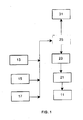
- the stopping method according to the present invention can be implemented using the control means available in known variable speed wind turbines as shown in Figure 1 .
- Pitch control means involve blades 11, an actuator 23, an adjusting transmission 21 and a control device 25.
- the control device 25 receives input data from the generator 13, and/or another wind turbine component 15, 17 and sends output data to the actuator 23 for changing the angular position of the blades 11 according to predefined rules.
- the control device 25 is also connected to the disk brake 31 to be able to command its activation.
- control device 25 is a second control device that will work failsafe in case of an emergency shut down caused by a failure in the first control device.
- control device 25 when the control device 25 receives the signal corresponding to an emergency stop sends output data to the actuator 23 for changing the angular position of the blades 11 towards the feathered position.
- a second stage initiated when the control device 25 detects that the rotational speed of the high speed shaft is under a predefined value So or any of the other above-mentioned conditions sends an activation signal to the disk brake 31.
- the method could be designed so that in case of failure in control device 25 the stopping operation is automatic activated
- the disk brake needed for carrying out the stopping method according to the present invention does not need to be a brake capable of taking the wind turbine to standstill in any condition and consequently can be a smaller disk allowing a cost reduction.
- this brake can be designed to work only in an emergency stop and in an stop for maintenance where the whole wind turbine shall be hoisted for a certain period of time and there is a need of a redundant system to the rotor locking system.
Landscapes
- Engineering & Computer Science (AREA)
- Life Sciences & Earth Sciences (AREA)
- Sustainable Development (AREA)
- Sustainable Energy (AREA)
- Chemical & Material Sciences (AREA)
- Combustion & Propulsion (AREA)
- Mechanical Engineering (AREA)
- General Engineering & Computer Science (AREA)
- Wind Motors (AREA)
Abstract
Description
- The invention relates to a method for stopping a wind turbine and more in particular to a method for stopping a wind turbine using aerodynamical and mechanical braking means.
- Wind turbines are devices that convert mechanical energy to electrical energy. A typical wind turbine includes a nacelle mounted on a tower housing a drive train for transmitting the rotation of a rotor to an electric generator.
- The efficiency of a wind turbine depends on many factors. One of them is the orientation of the rotor blades with respect to the direction of the air stream, which is usually controlled by a pitch system that allows adjusting the pitch angle of the rotor blades for maintaining the rotor's speed at a constant value or within a given range. Otherwise, specially at high wind speeds, the load of the rotor will exceed the limits set by the wind turbine's structural strength.
- There are two basic methods for controlling the power of a wind turbine changing the pitch angle of the rotor blades: the "pitch" control method and the "stall" control method. In the "pitch" control method the rotor blade's pitch angle is changed to a smaller angle of attack in order to reduce power capture and to a greater angle of attack to increase the power capture. This method allows a sensitive and stable control of the aerodynamic power capture and rotor speed.
- The stopping of a wind turbine is one of the most critical operations because it may involve high loads for the wind turbine components.
- In general terms, in pitch controlled wind turbines any stopping operation includes an step of pitching the blades towards the feathered position but there are known very different stopping methods such as the following.
-
EP 1 701 034 A2 discloses a method for stopping the rotor of a wind pliant when the blade angles are in the operating position and the tower is inclined to the direction of the wind in which the blade angles of the blades of the rotor are adjusted from the operating position towards the feathered position so that at the first step, the blades angles are turned at the first blade angle speed so that the rotor brakes; at the second step, the blade angle speed is reduced so that while in the operating position, the rotor acts to soften the pendulous motion of the tower against the wind. -
US 2007/0116572 A1 discloses a method for braking a wind turbine that includes selectively controlling an angle of pitch of at least one- rotor blade with respect to a wind direction based on a design parameter of a component of the wind turbine to facilitate reducing a force induced into the wind turbine component as a result of braking. - The stopping of a wind turbine may be carried out using different specific braking means that can be grouped in two categories: mechanical brakes and aerodynamic brakes such as air brakes, leading edge flaps or swing tips.
- In wind turbines with gearbox with three stages, mechanical brakes (typically disk brakes) are usually placed in the high speed shaft because there is a relatively low torque on it. The lower the torque the smaller will the disk brake be. In wind turbines with no gearbox or gearboxes with only two stages the torque will be higher and hence the disk brake needs to be larger.
- Modern wind turbines require optimised stopping methods and the present invention is intended to attend this demand.
- An object of the invention is to provide a method for stopping a pitch controlled wind turbine that enable the reduction of the size of the mechanical brake.
- This and other objects of the present invention are met by providing a method for stopping a pitch controlled wind turbine comprising a rotor with at least one blade, a mechanical brake on the high speed shaft, a pitch system for adjusting the blade pitch angle, that includes:
- A first stage using the pitch system for slowing down the rotor.
- A second stage using both the pitch system and the mechanical brake for stopping the rotor.
- In several embodiments, the second stage begins when the high speed shaft rotational speed is under a predefined value So, or when a time delay To with respect to the beginning of the first stage is reached, or when a predefined high speed shaft torque level TLo is reached. In all cases, a stopping method is achieved that can be implemented with a mechanical brake having a limited braking torque.
- Other features and advantages of the present invention will be understood from the following detailed description in relation with the enclosed drawings.
-
-
Figure 1 is a block diagram of the method of this invention. - Modern pitch controlled wind turbines use operational strategies intended to avoid as much as possible shutdowns that reduce the power production.
- In any case, the administrative regulations in many jurisdictions require that wind turbines shall be provided with at least two braking systems able to control the rotor speed so that modern wind turbines are provided on the one hand with the aerodynamic braking functionalities of the pitch control means and on the other hand with specific braking means such as a mechanical disk brake placed on the high speed shaft.
- Both braking systems can be used in very different manners in wind turbine stopping operations.
- The stopping method according to a preferred embodiment of the present invention which is particularly applicable for an emergency stop is carried out in two stages:
- In the first stage the blades will start feathering as soon as the stopping operation in started. Thus only an aerodynamic braking is used in this stage.
- In the second stage the blades will keep on feathering and the mechanical brake will start working once a predefined rotational speed, So, on the high speed shaft is achieved. Thus both an aerodynamic and a mechanical braking are used in this stage.
- Depending on the capacity of the disk brake and said predefined rotational speed, So, of the high speed shaft, the time needed for taking the wind turbine to complete stop will differ, as well as the heat generated (that will have to be evacuated) in such an event (collaterally stress and temperatures in the disk). It is particularly important to take into account that if the temperature is too high the braking effect will decrease and then the temperature will increase even more, just like when one drives a car using the brakes all the time and not the engine for braking, so that at the end the brakes are so hot that they can not stop the car.
- Once said predefined rotational speed, So, is achieved, in a typical disk brake it may take 0.1 seconds to the hydraulic group to start applying pressure and from that it may take 0.3 seconds later (0.4 seconds in overall) until the rated braking torque is achieved. In case of an electrical or pneumatic activated disk brake, the reaction times will be different.
- There are two basic limitations for selecting the rotational speed, So, of the high speed shaft at which the brake will start working. These are:
- It should not be very high (i.e. above 25% of nominal rpm) because otherwise the system will be applied too long, with the corresponding increase in temperature in the disk. Besides that, due to the low capacity of the mechanical brake compared to the aerodynamic one, the whole brake event duration will not be influenced.
- It should not be very low (i.e. below 5% of nominal rpm) because, otherwise we could risk that such speed is not achieved at any time, in the sense that the idling speed is above this value.
- A suitable value for So could be, for instance, 10-15% of nominal rpm.
- In another preferred embodiment, the mechanical brake will start working once a predefined time delay To with respect to the beginning of the first stage is reached.
- When stopping the turbine the blades will pitch to feathered position and the brake should be applied just before the blades reaches the feathered position, so that the turbine could be brought to a complete stop. With a pitch speed of 10 deg/sec and a pitch movement of 90 deg, the To could be 8 sec. If the pitch action to stop the turbine is performed in several pitch speed steps or variable pitch speed the stopping time could be 30-40 sec. So the disk brake should be applied after 8-35 sec depending on the method the pitch is brought to feathered position
- In another preferred embodiment the mechanical brake will start working when a predefined high speed shaft torque level TLo is reached. This torque level could be measured on the shaft or evaluated from generator power and rpm (if the generator is kept connected during stopping).
- Said torque level TLo can be reached increasing the torque in the generator momentaneously or even just keeping the generator connected. In case of a permanent magnet generator the system could be short circuit to reach a braking torque. Also the power reference could be brought to above nominal power for a short period, as the electrical system will be able to cope with some extra power for a short period.
- A suitable value for TLo could be 30% of nominal torque.
- In another preferred embodiment the mechanical brake will start working when the first of the following conditions takes place: either the high speed shaft rotational speed is under a predefined value So, or a predefined time delay To with respect to the beginning of the first stage is reached.
- In another preferred embodiment the mechanical brake will start working when the first of the following conditions takes place: either the high speed shaft rotational speed is under a predefined value So, or a predefined time delay To with respect to the beginning of the first stage is reached, or a predefined high speed shaft torque level TLo is reached.
- The stopping method according to the present invention can be implemented using the control means available in known variable speed wind turbines as shown in
Figure 1 . - Pitch control means involve
blades 11, anactuator 23, an adjustingtransmission 21 and acontrol device 25. Thecontrol device 25 receives input data from thegenerator 13, and/or anotherwind turbine component actuator 23 for changing the angular position of theblades 11 according to predefined rules. Thecontrol device 25 is also connected to thedisk brake 31 to be able to command its activation. - In a preferred embodiment said
control device 25 is a second control device that will work failsafe in case of an emergency shut down caused by a failure in the first control device. - According to the method of this invention, when the
control device 25 receives the signal corresponding to an emergency stop sends output data to theactuator 23 for changing the angular position of theblades 11 towards the feathered position. In a second stage, initiated when thecontrol device 25 detects that the rotational speed of the high speed shaft is under a predefined value So or any of the other above-mentioned conditions sends an activation signal to thedisk brake 31. - The method could be designed so that in case of failure in
control device 25 the stopping operation is automatic activated - The disk brake needed for carrying out the stopping method according to the present invention does not need to be a brake capable of taking the wind turbine to standstill in any condition and consequently can be a smaller disk allowing a cost reduction. In principle this brake can be designed to work only in an emergency stop and in an stop for maintenance where the whole wind turbine shall be hoisted for a certain period of time and there is a need of a redundant system to the rotor locking system.
- Although the present invention has been fully described in connection with preferred embodiments, it is evident that modifications may be introduced within the scope thereof, not considering this as limited by these embodiments, but by the contents of the following claims.
Claims (7)
- A method for stopping a pitch controlled wind turbine comprising a rotor with at least one blade (11), a mechanical brake (31) on the high speed shaft, a pitch system (21, 23, 25) for adjusting the blade pitch angle, characterized in that it includes:a) a first stage using the pitch system (21, 23, 25) for slowing down the rotor;b) a second stage using both the pitch system (21, 23, 25) and the mechanical brake (31) for stopping the rotor.
- A method for stopping a pitch controlled wind turbine according to claim 1, characterized in that the second stage begins when one of the following conditions takes place:- the high speed shaft rotational speed is under a predefined value So;- a predefined time delay To with respect to the beginning of the first stage is reached;- a predefined high speed shaft torque level TLo is reached.
- A method for stopping a pitch controlled wind turbine according to claim 1, characterized in that the second stage begins when the first of the following conditions takes place:- the high speed shaft rotational speed is under a predefined value So;- a predefined time delay To with respect to the beginning of the first stage is reached.
- A method for stopping a pitch controlled wind turbine according to claim 1, characterized in that the second stage begins when the first of the following conditions takes place:- the high speed shaft rotational speed is under a predefined value So;- a predefined time delay To with respect to the beginning of the first stage is reached;- a predefined high speed shaft torque level TLo is reached.
- A method for stopping a pitch controlled wind turbine according to any of claims 2-4, characterized in that said high speed shaft rotational speed predefined value So is comprised in the range of 10% to 15% the nominal rotational speed.
- A method for stopping a pitch controlled wind turbine according to any of claims 2-4, characterized in that said predefined time delay To is comprised between 8 and 35 sec.
- A method for stopping a pitch controlled wind turbine according to any of claims 2 and 4, characterized in that said high speed shaft torque level predefined value TLo is 30% of the nominal torque.
Applications Claiming Priority (1)
| Application Number | Priority Date | Filing Date | Title |
|---|---|---|---|
| ES200802646A ES2358711B1 (en) | 2008-09-18 | 2008-09-18 | METHOD TO STOP AN AIRBRUSHER IN TWO STAGES. |
Publications (3)
| Publication Number | Publication Date |
|---|---|
| EP2166224A2 true EP2166224A2 (en) | 2010-03-24 |
| EP2166224A3 EP2166224A3 (en) | 2016-08-10 |
| EP2166224B1 EP2166224B1 (en) | 2018-09-12 |
Family
ID=41478713
Family Applications (1)
| Application Number | Title | Priority Date | Filing Date |
|---|---|---|---|
| EP09011887.8A Not-in-force EP2166224B1 (en) | 2008-09-18 | 2009-09-17 | A method for stopping a wind turbine in two stages |
Country Status (5)
| Country | Link |
|---|---|
| US (1) | US20100068057A1 (en) |
| EP (1) | EP2166224B1 (en) |
| CN (1) | CN101709689B (en) |
| DK (1) | DK2166224T3 (en) |
| ES (1) | ES2358711B1 (en) |
Families Citing this family (19)
| Publication number | Priority date | Publication date | Assignee | Title |
|---|---|---|---|---|
| JP5566609B2 (en) * | 2009-01-05 | 2014-08-06 | 三菱重工業株式会社 | Wind power generator and control method for wind power generator |
| CN102619688A (en) * | 2012-04-18 | 2012-08-01 | 中船重工(重庆)海装风电设备有限公司 | Wind turbine generator system brake control device and wind turbine generator system brake control method |
| CN103266987B (en) * | 2013-05-22 | 2015-05-20 | 北京金风科创风电设备有限公司 | Wind driven generator stopping method under single blade clamping working condition |
| CN103967704B (en) * | 2014-05-16 | 2017-11-21 | 北京金风科创风电设备有限公司 | Control method and control system for locking impeller of wind generating set |
| US9745958B2 (en) | 2014-06-30 | 2017-08-29 | General Electric Company | Method and system for managing loads on a wind turbine |
| CN104832369B (en) * | 2015-04-21 | 2018-03-30 | 三一重型能源装备有限公司 | Wheel hub automatic matching system and control method and wind-driven generator |
| DE102015110715A1 (en) * | 2015-07-02 | 2017-01-05 | Ssb Wind Systems Gmbh & Co. Kg | Method for controlling a rotor blade adjusting device |
| CN105134492B (en) * | 2015-08-21 | 2018-03-02 | 东方电气风电有限公司 | Mitigate the method for wind-driven generator wheel-box rippling |
| US9920743B2 (en) * | 2015-10-21 | 2018-03-20 | General Electric Company | Wind turbine deceleration method and system |
| CN105781877B (en) * | 2016-03-04 | 2018-09-11 | 北京金风科创风电设备有限公司 | Shutdown control method, device and system of wind generating set |
| CN106121914B (en) * | 2016-08-26 | 2018-11-23 | 三一重型能源装备有限公司 | The closing method and system of blower under extremity |
| US11268493B2 (en) * | 2017-08-24 | 2022-03-08 | Vestas Wind Systems A/S | Wind turbine safety brake control strategy |
| CN109322787B (en) * | 2018-09-10 | 2019-10-25 | 许继集团有限公司 | A method and device for controlling shutdown of a wind power generating set |
| CN110067699B (en) * | 2019-05-27 | 2024-03-08 | 大连交通大学 | High-speed heavy-load working condition variable pressure mechanical braking method and large megawatt wind turbine mechanical braking system |
| ES3013289T3 (en) | 2019-06-24 | 2025-04-11 | Vestas Wind Sys As | Method of shutting down a wind turbine |
| CN114303012B (en) | 2019-06-27 | 2025-02-18 | 维斯塔斯风力系统集团公司 | Controlling wind turbine power output below rated wind speed |
| CN111306012B (en) * | 2020-03-05 | 2021-03-19 | 山东中车风电有限公司 | Method for correcting deviation of connecting surface of transmission main shaft of wind generating set |
| DK181381B1 (en) * | 2021-11-19 | 2023-09-19 | Shanghai electric wind power group co ltd | A wind turbine and controller, method and computer program product for wind turbine |
| CN120346858A (en) * | 2025-06-17 | 2025-07-22 | 四川钭进科技有限公司 | Automatic control method and system for full-automatic shutdown based on rice mill |
Citations (2)
| Publication number | Priority date | Publication date | Assignee | Title |
|---|---|---|---|---|
| EP1701034A2 (en) | 2005-03-09 | 2006-09-13 | Winwind Oy | Method for stopping the rotor of a wind power plant |
| US20070116572A1 (en) | 2005-11-18 | 2007-05-24 | Corneliu Barbu | Method and apparatus for wind turbine braking |
Family Cites Families (6)
| Publication number | Priority date | Publication date | Assignee | Title |
|---|---|---|---|---|
| US6265785B1 (en) * | 1998-11-30 | 2001-07-24 | Zond Systems, Inc. | Non-volatile over speed control system for wind turbines |
| US7175389B2 (en) * | 2004-06-30 | 2007-02-13 | General Electric Company | Methods and apparatus for reducing peak wind turbine loads |
| EP1774172A1 (en) * | 2004-07-28 | 2007-04-18 | The General Electric Company | Mechanical emergency brake for wind turbines and method for operating same |
| EP2450568B1 (en) * | 2005-05-31 | 2018-04-18 | Hitachi, Ltd. | Horizontal axis wind turbine |
| DE102006001613B4 (en) * | 2006-01-11 | 2008-01-31 | Repower Systems Ag | Method for operating a wind turbine and wind turbine |
| US7586216B2 (en) * | 2006-06-02 | 2009-09-08 | General Electric Company | Redundant electrical brake and protection system for electric generators |
-
2008
- 2008-09-18 ES ES200802646A patent/ES2358711B1/en not_active Expired - Fee Related
-
2009
- 2009-09-17 US US12/561,316 patent/US20100068057A1/en not_active Abandoned
- 2009-09-17 DK DK09011887.8T patent/DK2166224T3/en active
- 2009-09-17 EP EP09011887.8A patent/EP2166224B1/en not_active Not-in-force
- 2009-09-18 CN CN200910221413.1A patent/CN101709689B/en not_active Expired - Fee Related
Patent Citations (2)
| Publication number | Priority date | Publication date | Assignee | Title |
|---|---|---|---|---|
| EP1701034A2 (en) | 2005-03-09 | 2006-09-13 | Winwind Oy | Method for stopping the rotor of a wind power plant |
| US20070116572A1 (en) | 2005-11-18 | 2007-05-24 | Corneliu Barbu | Method and apparatus for wind turbine braking |
Also Published As
| Publication number | Publication date |
|---|---|
| DK2166224T3 (en) | 2018-12-17 |
| US20100068057A1 (en) | 2010-03-18 |
| EP2166224B1 (en) | 2018-09-12 |
| ES2358711A1 (en) | 2011-05-13 |
| CN101709689B (en) | 2014-08-13 |
| CN101709689A (en) | 2010-05-19 |
| EP2166224A3 (en) | 2016-08-10 |
| ES2358711B1 (en) | 2012-03-23 |
Similar Documents
| Publication | Publication Date | Title |
|---|---|---|
| EP2166224B1 (en) | A method for stopping a wind turbine in two stages | |
| DK3112676T3 (en) | PROCEDURE FOR OPERATING A WINDOW ENERGY INSTALLATION AND A WINDOW ENERGY INSTALLATION | |
| US7175389B2 (en) | Methods and apparatus for reducing peak wind turbine loads | |
| CN101096941B (en) | Wind energy device having the engine room and rotor | |
| CN102705161B (en) | Method and system for braking in wind turbine | |
| EP2698534B1 (en) | System and method for braking a wind turbine rotor at an overspeed condition | |
| EP3643915B1 (en) | System and method for application of a brake for a wind turbine | |
| EP2096300A2 (en) | Method of controlling the tip speed ratio of wind turbine blades | |
| EP2336558A2 (en) | Method of operating a variable speed wind turbine | |
| US20110140425A1 (en) | Method and System For Controlling Wind Turbine Rotational Speed | |
| EP2963286A1 (en) | Windturbine and method for stopping the same | |
| EP2466124A2 (en) | Hydraulic yaw drive system for a wind turbine and method of operating the same | |
| US8348617B2 (en) | Method for the emergency braking of a wind power plant and a wind power plant with a rotor blade pitch control for emergency braking | |
| WO2009138409A1 (en) | Method of reducing torsional oscillations in the power train of a wind turbine | |
| CN115929548A (en) | Intelligent yaw control system and method for wind turbines used in complex mountainous areas | |
| EP3892850B1 (en) | System and method for mitigating loads acting on a rotor blade of a wind turbine | |
| KR101363516B1 (en) | Method for controlling a generator of wind turbine generator | |
| CN101498280B (en) | Method for stopping a wind turbine | |
| EP3699421B1 (en) | Method of dynamically adjusting a rate of change of a rotor speed set point during wind turbine shutdown | |
| US12398693B2 (en) | Method for controlling a wind turbine during yaw operation | |
| EP3597906B1 (en) | System and method for reducing loads of a wind turbine when a rotor blade becomes stuck | |
| CN117267050A (en) | Anti-flying control system and control method for wind generating set |
Legal Events
| Date | Code | Title | Description |
|---|---|---|---|
| PUAI | Public reference made under article 153(3) epc to a published international application that has entered the european phase |
Free format text: ORIGINAL CODE: 0009012 |
|
| AK | Designated contracting states |
Kind code of ref document: A2 Designated state(s): AT BE BG CH CY CZ DE DK EE ES FI FR GB GR HR HU IE IS IT LI LT LU LV MC MK MT NL NO PL PT RO SE SI SK SM TR |
|
| AX | Request for extension of the european patent |
Extension state: AL BA RS |
|
| PUAL | Search report despatched |
Free format text: ORIGINAL CODE: 0009013 |
|
| AK | Designated contracting states |
Kind code of ref document: A3 Designated state(s): AT BE BG CH CY CZ DE DK EE ES FI FR GB GR HR HU IE IS IT LI LT LU LV MC MK MT NL NO PL PT RO SE SI SK SM TR |
|
| AX | Request for extension of the european patent |
Extension state: AL BA RS |
|
| RIC1 | Information provided on ipc code assigned before grant |
Ipc: F03D 7/02 20060101AFI20160705BHEP |
|
| 17P | Request for examination filed |
Effective date: 20170123 |
|
| RBV | Designated contracting states (corrected) |
Designated state(s): AT BE BG CH CY CZ DE DK EE ES FI FR GB GR HR HU IE IS IT LI LT LU LV MC MK MT NL NO PL PT RO SE SI SK SM TR |
|
| 17Q | First examination report despatched |
Effective date: 20170731 |
|
| GRAP | Despatch of communication of intention to grant a patent |
Free format text: ORIGINAL CODE: EPIDOSNIGR1 |
|
| INTG | Intention to grant announced |
Effective date: 20180430 |
|
| GRAS | Grant fee paid |
Free format text: ORIGINAL CODE: EPIDOSNIGR3 |
|
| GRAA | (expected) grant |
Free format text: ORIGINAL CODE: 0009210 |
|
| AK | Designated contracting states |
Kind code of ref document: B1 Designated state(s): AT BE BG CH CY CZ DE DK EE ES FI FR GB GR HR HU IE IS IT LI LT LU LV MC MK MT NL NO PL PT RO SE SI SK SM TR |
|
| REG | Reference to a national code |
Ref country code: GB Ref legal event code: FG4D |
|
| REG | Reference to a national code |
Ref country code: CH Ref legal event code: EP |
|
| REG | Reference to a national code |
Ref country code: IE Ref legal event code: FG4D |
|
| REG | Reference to a national code |
Ref country code: DE Ref legal event code: R096 Ref document number: 602009054428 Country of ref document: DE |
|
| REG | Reference to a national code |
Ref country code: AT Ref legal event code: REF Ref document number: 1040900 Country of ref document: AT Kind code of ref document: T Effective date: 20181015 |
|
| REG | Reference to a national code |
Ref country code: DK Ref legal event code: T3 Effective date: 20181210 |
|
| REG | Reference to a national code |
Ref country code: NL Ref legal event code: MP Effective date: 20180912 |
|
| REG | Reference to a national code |
Ref country code: LT Ref legal event code: MG4D |
|
| PG25 | Lapsed in a contracting state [announced via postgrant information from national office to epo] |
Ref country code: LT Free format text: LAPSE BECAUSE OF FAILURE TO SUBMIT A TRANSLATION OF THE DESCRIPTION OR TO PAY THE FEE WITHIN THE PRESCRIBED TIME-LIMIT Effective date: 20180912 Ref country code: SE Free format text: LAPSE BECAUSE OF FAILURE TO SUBMIT A TRANSLATION OF THE DESCRIPTION OR TO PAY THE FEE WITHIN THE PRESCRIBED TIME-LIMIT Effective date: 20180912 Ref country code: BG Free format text: LAPSE BECAUSE OF FAILURE TO SUBMIT A TRANSLATION OF THE DESCRIPTION OR TO PAY THE FEE WITHIN THE PRESCRIBED TIME-LIMIT Effective date: 20181212 Ref country code: NO Free format text: LAPSE BECAUSE OF FAILURE TO SUBMIT A TRANSLATION OF THE DESCRIPTION OR TO PAY THE FEE WITHIN THE PRESCRIBED TIME-LIMIT Effective date: 20181212 Ref country code: GR Free format text: LAPSE BECAUSE OF FAILURE TO SUBMIT A TRANSLATION OF THE DESCRIPTION OR TO PAY THE FEE WITHIN THE PRESCRIBED TIME-LIMIT Effective date: 20181213 Ref country code: FI Free format text: LAPSE BECAUSE OF FAILURE TO SUBMIT A TRANSLATION OF THE DESCRIPTION OR TO PAY THE FEE WITHIN THE PRESCRIBED TIME-LIMIT Effective date: 20180912 |
|
| PG25 | Lapsed in a contracting state [announced via postgrant information from national office to epo] |
Ref country code: HR Free format text: LAPSE BECAUSE OF FAILURE TO SUBMIT A TRANSLATION OF THE DESCRIPTION OR TO PAY THE FEE WITHIN THE PRESCRIBED TIME-LIMIT Effective date: 20180912 Ref country code: ES Free format text: LAPSE BECAUSE OF FAILURE TO SUBMIT A TRANSLATION OF THE DESCRIPTION OR TO PAY THE FEE WITHIN THE PRESCRIBED TIME-LIMIT Effective date: 20180912 Ref country code: LV Free format text: LAPSE BECAUSE OF FAILURE TO SUBMIT A TRANSLATION OF THE DESCRIPTION OR TO PAY THE FEE WITHIN THE PRESCRIBED TIME-LIMIT Effective date: 20180912 |
|
| REG | Reference to a national code |
Ref country code: AT Ref legal event code: MK05 Ref document number: 1040900 Country of ref document: AT Kind code of ref document: T Effective date: 20180912 |
|
| RAP2 | Party data changed (patent owner data changed or rights of a patent transferred) |
Owner name: SIEMENS GAMESA RENEWABLE ENERGY INNOVATION & TECHN |
|
| PG25 | Lapsed in a contracting state [announced via postgrant information from national office to epo] |
Ref country code: AT Free format text: LAPSE BECAUSE OF FAILURE TO SUBMIT A TRANSLATION OF THE DESCRIPTION OR TO PAY THE FEE WITHIN THE PRESCRIBED TIME-LIMIT Effective date: 20180912 Ref country code: IS Free format text: LAPSE BECAUSE OF FAILURE TO SUBMIT A TRANSLATION OF THE DESCRIPTION OR TO PAY THE FEE WITHIN THE PRESCRIBED TIME-LIMIT Effective date: 20190112 Ref country code: NL Free format text: LAPSE BECAUSE OF FAILURE TO SUBMIT A TRANSLATION OF THE DESCRIPTION OR TO PAY THE FEE WITHIN THE PRESCRIBED TIME-LIMIT Effective date: 20180912 Ref country code: EE Free format text: LAPSE BECAUSE OF FAILURE TO SUBMIT A TRANSLATION OF THE DESCRIPTION OR TO PAY THE FEE WITHIN THE PRESCRIBED TIME-LIMIT Effective date: 20180912 Ref country code: RO Free format text: LAPSE BECAUSE OF FAILURE TO SUBMIT A TRANSLATION OF THE DESCRIPTION OR TO PAY THE FEE WITHIN THE PRESCRIBED TIME-LIMIT Effective date: 20180912 Ref country code: IT Free format text: LAPSE BECAUSE OF FAILURE TO SUBMIT A TRANSLATION OF THE DESCRIPTION OR TO PAY THE FEE WITHIN THE PRESCRIBED TIME-LIMIT Effective date: 20180912 Ref country code: PL Free format text: LAPSE BECAUSE OF FAILURE TO SUBMIT A TRANSLATION OF THE DESCRIPTION OR TO PAY THE FEE WITHIN THE PRESCRIBED TIME-LIMIT Effective date: 20180912 Ref country code: CZ Free format text: LAPSE BECAUSE OF FAILURE TO SUBMIT A TRANSLATION OF THE DESCRIPTION OR TO PAY THE FEE WITHIN THE PRESCRIBED TIME-LIMIT Effective date: 20180912 |
|
| REG | Reference to a national code |
Ref country code: CH Ref legal event code: PL |
|
| PG25 | Lapsed in a contracting state [announced via postgrant information from national office to epo] |
Ref country code: PT Free format text: LAPSE BECAUSE OF FAILURE TO SUBMIT A TRANSLATION OF THE DESCRIPTION OR TO PAY THE FEE WITHIN THE PRESCRIBED TIME-LIMIT Effective date: 20190112 Ref country code: SM Free format text: LAPSE BECAUSE OF FAILURE TO SUBMIT A TRANSLATION OF THE DESCRIPTION OR TO PAY THE FEE WITHIN THE PRESCRIBED TIME-LIMIT Effective date: 20180912 Ref country code: SK Free format text: LAPSE BECAUSE OF FAILURE TO SUBMIT A TRANSLATION OF THE DESCRIPTION OR TO PAY THE FEE WITHIN THE PRESCRIBED TIME-LIMIT Effective date: 20180912 |
|
| REG | Reference to a national code |
Ref country code: BE Ref legal event code: MM Effective date: 20180930 |
|
| REG | Reference to a national code |
Ref country code: DE Ref legal event code: R097 Ref document number: 602009054428 Country of ref document: DE |
|
| REG | Reference to a national code |
Ref country code: IE Ref legal event code: MM4A |
|
| PG25 | Lapsed in a contracting state [announced via postgrant information from national office to epo] |
Ref country code: LU Free format text: LAPSE BECAUSE OF NON-PAYMENT OF DUE FEES Effective date: 20180917 |
|
| PLBE | No opposition filed within time limit |
Free format text: ORIGINAL CODE: 0009261 |
|
| STAA | Information on the status of an ep patent application or granted ep patent |
Free format text: STATUS: NO OPPOSITION FILED WITHIN TIME LIMIT |
|
| PG25 | Lapsed in a contracting state [announced via postgrant information from national office to epo] |
Ref country code: MC Free format text: LAPSE BECAUSE OF FAILURE TO SUBMIT A TRANSLATION OF THE DESCRIPTION OR TO PAY THE FEE WITHIN THE PRESCRIBED TIME-LIMIT Effective date: 20180912 Ref country code: IE Free format text: LAPSE BECAUSE OF NON-PAYMENT OF DUE FEES Effective date: 20180917 |
|
| 26N | No opposition filed |
Effective date: 20190613 |
|
| PG25 | Lapsed in a contracting state [announced via postgrant information from national office to epo] |
Ref country code: SI Free format text: LAPSE BECAUSE OF FAILURE TO SUBMIT A TRANSLATION OF THE DESCRIPTION OR TO PAY THE FEE WITHIN THE PRESCRIBED TIME-LIMIT Effective date: 20180912 Ref country code: CH Free format text: LAPSE BECAUSE OF NON-PAYMENT OF DUE FEES Effective date: 20180930 Ref country code: BE Free format text: LAPSE BECAUSE OF NON-PAYMENT OF DUE FEES Effective date: 20180930 Ref country code: LI Free format text: LAPSE BECAUSE OF NON-PAYMENT OF DUE FEES Effective date: 20180930 |
|
| PG25 | Lapsed in a contracting state [announced via postgrant information from national office to epo] |
Ref country code: FR Free format text: LAPSE BECAUSE OF NON-PAYMENT OF DUE FEES Effective date: 20181112 |
|
| PG25 | Lapsed in a contracting state [announced via postgrant information from national office to epo] |
Ref country code: MT Free format text: LAPSE BECAUSE OF NON-PAYMENT OF DUE FEES Effective date: 20180917 |
|
| PG25 | Lapsed in a contracting state [announced via postgrant information from national office to epo] |
Ref country code: TR Free format text: LAPSE BECAUSE OF FAILURE TO SUBMIT A TRANSLATION OF THE DESCRIPTION OR TO PAY THE FEE WITHIN THE PRESCRIBED TIME-LIMIT Effective date: 20180912 |
|
| PG25 | Lapsed in a contracting state [announced via postgrant information from national office to epo] |
Ref country code: HU Free format text: LAPSE BECAUSE OF FAILURE TO SUBMIT A TRANSLATION OF THE DESCRIPTION OR TO PAY THE FEE WITHIN THE PRESCRIBED TIME-LIMIT; INVALID AB INITIO Effective date: 20090917 |
|
| PG25 | Lapsed in a contracting state [announced via postgrant information from national office to epo] |
Ref country code: MK Free format text: LAPSE BECAUSE OF NON-PAYMENT OF DUE FEES Effective date: 20180912 Ref country code: CY Free format text: LAPSE BECAUSE OF FAILURE TO SUBMIT A TRANSLATION OF THE DESCRIPTION OR TO PAY THE FEE WITHIN THE PRESCRIBED TIME-LIMIT Effective date: 20180912 |
|
| PGFP | Annual fee paid to national office [announced via postgrant information from national office to epo] |
Ref country code: DK Payment date: 20200922 Year of fee payment: 12 |
|
| PGFP | Annual fee paid to national office [announced via postgrant information from national office to epo] |
Ref country code: DE Payment date: 20201118 Year of fee payment: 12 Ref country code: GB Payment date: 20201002 Year of fee payment: 12 |
|
| REG | Reference to a national code |
Ref country code: DE Ref legal event code: R119 Ref document number: 602009054428 Country of ref document: DE |
|
| REG | Reference to a national code |
Ref country code: DK Ref legal event code: EBP Effective date: 20210930 |
|
| GBPC | Gb: european patent ceased through non-payment of renewal fee |
Effective date: 20210917 |
|
| PG25 | Lapsed in a contracting state [announced via postgrant information from national office to epo] |
Ref country code: GB Free format text: LAPSE BECAUSE OF NON-PAYMENT OF DUE FEES Effective date: 20210917 Ref country code: DE Free format text: LAPSE BECAUSE OF NON-PAYMENT OF DUE FEES Effective date: 20220401 |
|
| PG25 | Lapsed in a contracting state [announced via postgrant information from national office to epo] |
Ref country code: DK Free format text: LAPSE BECAUSE OF NON-PAYMENT OF DUE FEES Effective date: 20210930 |