EP2166213A2 - Air filter mounting system and method for fabricating the same - Google Patents
Air filter mounting system and method for fabricating the same Download PDFInfo
- Publication number
- EP2166213A2 EP2166213A2 EP09170327A EP09170327A EP2166213A2 EP 2166213 A2 EP2166213 A2 EP 2166213A2 EP 09170327 A EP09170327 A EP 09170327A EP 09170327 A EP09170327 A EP 09170327A EP 2166213 A2 EP2166213 A2 EP 2166213A2
- Authority
- EP
- European Patent Office
- Prior art keywords
- retaining nut
- cavity
- accordance
- locking plate
- sized
- Prior art date
- Legal status (The legal status is an assumption and is not a legal conclusion. Google has not performed a legal analysis and makes no representation as to the accuracy of the status listed.)
- Withdrawn
Links
- 238000000034 method Methods 0.000 title claims description 19
- 238000007789 sealing Methods 0.000 claims abstract description 27
- 230000008878 coupling Effects 0.000 claims abstract description 19
- 238000010168 coupling process Methods 0.000 claims abstract description 19
- 238000005859 coupling reaction Methods 0.000 claims abstract description 19
- 238000002347 injection Methods 0.000 claims description 3
- 239000007924 injection Substances 0.000 claims description 3
- 230000006870 function Effects 0.000 description 6
- 238000001914 filtration Methods 0.000 description 4
- 238000013461 design Methods 0.000 description 3
- 230000001012 protector Effects 0.000 description 3
- 230000000712 assembly Effects 0.000 description 2
- 238000000429 assembly Methods 0.000 description 2
- 238000009434 installation Methods 0.000 description 2
- 238000007792 addition Methods 0.000 description 1
- 238000005452 bending Methods 0.000 description 1
- 238000012217 deletion Methods 0.000 description 1
- 230000037430 deletion Effects 0.000 description 1
- 230000007717 exclusion Effects 0.000 description 1
- 238000001746 injection moulding Methods 0.000 description 1
- JEIPFZHSYJVQDO-UHFFFAOYSA-N iron(III) oxide Inorganic materials O=[Fe]O[Fe]=O JEIPFZHSYJVQDO-UHFFFAOYSA-N 0.000 description 1
- 238000012423 maintenance Methods 0.000 description 1
- 239000002184 metal Substances 0.000 description 1
- 238000012986 modification Methods 0.000 description 1
- 230000004048 modification Effects 0.000 description 1
- 230000002093 peripheral effect Effects 0.000 description 1
- 238000003466 welding Methods 0.000 description 1
Images



Classifications
-
- B—PERFORMING OPERATIONS; TRANSPORTING
- B01—PHYSICAL OR CHEMICAL PROCESSES OR APPARATUS IN GENERAL
- B01D—SEPARATION
- B01D46/00—Filters or filtering processes specially modified for separating dispersed particles from gases or vapours
- B01D46/0002—Casings; Housings; Frame constructions
-
- B—PERFORMING OPERATIONS; TRANSPORTING
- B01—PHYSICAL OR CHEMICAL PROCESSES OR APPARATUS IN GENERAL
- B01D—SEPARATION
- B01D46/00—Filters or filtering processes specially modified for separating dispersed particles from gases or vapours
- B01D46/42—Auxiliary equipment or operation thereof
- B01D46/4227—Manipulating filters or filter elements, e.g. handles or extracting tools
-
- B—PERFORMING OPERATIONS; TRANSPORTING
- B01—PHYSICAL OR CHEMICAL PROCESSES OR APPARATUS IN GENERAL
- B01D—SEPARATION
- B01D2271/00—Sealings for filters specially adapted for separating dispersed particles from gases or vapours
- B01D2271/02—Gaskets, sealings
- B01D2271/027—Radial sealings
-
- B—PERFORMING OPERATIONS; TRANSPORTING
- B01—PHYSICAL OR CHEMICAL PROCESSES OR APPARATUS IN GENERAL
- B01D—SEPARATION
- B01D2279/00—Filters adapted for separating dispersed particles from gases or vapours specially modified for specific uses
- B01D2279/60—Filters adapted for separating dispersed particles from gases or vapours specially modified for specific uses for the intake of internal combustion engines or turbines
Definitions
- the field of the disclosure relates generally to air filtration systems, and more specifically to air filter mounting assemblies.
- Some known air intake filter systems used on gas turbine engines include a housing that houses a removable, replaceable filter cartridge. At least some known filter cartridges include an annular array of pleated paper that cooperates with a wall of the housing to define an inlet chamber, and an outlet chamber within the cartridge that communicates with a housing outlet defined in one end of the housing. Some known housings include a plurality of support legs that are coupled at one end using a bolt that extends through a hole defined in each leg. Such housings require each leg to be assembled in sequence and coupled to one another using a specially-designed carriage bolt.
- the filter cartridge is coupled within the housing using a washer, and a filter retaining nut. Additionally in some known systems a rubber seal is coupled between the filter cartridge and the washer/nut combination to prevent contaminates from being introduced into the air intake of the engine. Moreover, in some known systems, a separate thread protector is positioned over an end of the exposed bolt threads to provide personal protection during filter change-out and maintenance operations from potentially sharp edges of the threads.
- a separate thread protector is positioned over an end of the exposed bolt threads to provide personal protection during filter change-out and maintenance operations from potentially sharp edges of the threads.
- such a system is generally time consuming to assemble because of the many individual components that may potentially be installed incorrectly, and/or dropped or lost during assembly.
- the use of a conventional washer/nut combination may also require an operator to use additional tools to assemble and tighten the filter cartridge components into place.
- an air filter mounting system in one aspect, includes a filter mounting element extending from an air intake, wherein the filter mounting element includes a locking plate, a filter support bolt coupled to and extending outward from the locking plate, a plurality of support legs extending from the air intake, wherein the plurality of support legs coupled to the locking plate, and a retaining nut sized to threadably engage the filter support bolt.
- the retaining nut includes a handle portion comprising a cavity defined therein, wherein the cavity is sized to receive at least a portion of a fastener therein, and an attachment portion including a threaded bore defined therein, wherein the attachment portion is sized to threadably receive the fastener therein, and wherein the threaded bore is substantially axially aligned with the cavity.
- the retaining nut includes a sealing skirt extending outward from the attachment portion and includes a flexible sealing surface.
- a retaining nut in another aspect, includes a handle portion having a cavity defined therein, wherein the cavity is sized to receive at least a portion of a fastener therein, and an attachment portion including a threaded bore defined therein, wherein the attachment portion is sized to threadably receive the fastener therein, and wherein the threaded bore is substantially axially aligned with the cavity.
- the retaining nut includes a sealing skirt extending outward from the attachment portion and includes a flexible sealing surface.
- a method for assembly an air filter mounting assembly includes coupling a plurality of support legs to a locking plate, coupling a threaded bolt to the locking plate such that a portion of the bolt extends outward from the locking plate, coupling the plurality of support legs to an outer periphery of an air intake, and coupling a retaining nut to the threaded bolt.
- the retaining nut includes a handle portion having a cavity defined therein, wherein the cavity is sized to receive at least a portion of a fastener therein.
- the retaining nut also includes an attachment portion that includes a threaded bore extending therethrough that is sized to receive the fastener therein, and a sealing skirt extending outward from the attachment portion includes a flexible sealing surface.
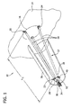
- FIG 1 is a perspective view of an exemplary air filter mounting system 10.
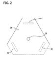
- Figure 2 is a schematic illustration of a locking plate 28 used with mounting system 10.
- air filter mounting system 10 includes a mounting assembly 12 that is coupled to and extends outward from a mounting surface 14, and more specifically, that is substantially centered about, and extending outward, from an air intake 16 defined on mounting surface 14.
- Mounting assembly 12 includes a plurality of legs 18, that each has a proximate end 20 and a distal end 22. Each proximate end 20 is coupled to mounting surface 14.
- each leg 18 is coupled circumferentially about air intake 16 using a bolt 24.
- mounting assembly 12 includes three legs 18 that each have a length L 1 and that are oriented in a tripod configuration 26.
- mounting assembly 12 may include any number of legs 18 coupled to mounting surface 14 in any orientation that enables air filter mounting system 10 to function as described herein.
- Each leg distal end 22 is coupled to locking plate 28.
- leg distal end 22 is welded to locking plate 28.
- each leg distal end 22 may be bolted locking plate 28, or coupled to locking plate by any coupling device that enables air filter mounting system 10 to function as described herein.
- locking plate 28 includes an aperture 30 that is sized to receive a threaded filter support bolt 32 therethough, such that the support bolt 32 extends outwardly from mounting surface 14, as shown in Figure 1 .
- mounting assembly 12 also includes a filter retaining nut 34 that includes a corresponding threaded aperture (not shown in Figure 1 ). Filter support bolt 32 is threadably coupled within the aperture to facilitate maintaining a filter 36 in a stationary position with respect to mounting assembly 12.
- each leg distal end 22 includes a flange 38 coupled to locking plate 28.
- Flange 38 may be formed by, for example, flattening and bending each leg distal end 22 to provide a hook-type flange thereto.
- flange may be formed by any method that enables air filter mounting system 10 to function as described herein.
- locking plate 28 includes a plurality of slots 40 defined therein that correspond to the number of legs 18 used with mounting assembly 12. Slots 40 are circumferentially spaced about locking plate 28 and each is sized and oriented to receive a respective flange 38 therein.
- mounting assembly 12 includes three legs 18 and locking plate 28 includes three corresponding slots 40.
- each distal end 22 may be coupled to locking plate 28 in any manner that enables air filter assembly 10 to function as described herein, including but not limited to bolting, welding, and/or friction fitting. Such a design reduces component count during assembly and facilitates the ease of installing mounting assembly 12 to mounting surface 14.
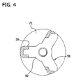
- Figures 3 , 4 , and 5 are respective side, end, and cross-sectional views of an exemplary air filter mounting nut 50 used with air filter mounting system 10.
- nut 50 is unitarily constructed by injection molding.
- nut 50 may be fabricated, for example, by joining individually molded or forged components.
- Nut 50 includes a handle portion 52 that includes an engaging end 54.
- handle portion 52 includes a contoured gripping surface 56 that has a substantially Y-shaped cross-sectional shape 58 that facilitates hand tightening of nut 50, as described in more detail herein.
- handle portion 52 may have a rectangular, circular, elliptical, or any other cross-sectional shape that enables air filter mounting system 10 to function as described herein.
- handle portion 52 may include a surface (not shown) that enables nut 50 to be tightened with a tool (not shown), such as, but not limited, to a wrench and/or a screwdriver.
- a tool such as, but not limited, to a wrench and/or a screwdriver.
- handle portion 52 provides a gripping surface that facilitates hand tightening without the need for additional tightening tools, thereby reducing part count for mounting system 10 and simplifying installation.
- Handle engaging end 54 includes a channel 60 that extends to a substantially hollow, elongated cavity 62, as shown in Figure 5 .
- a substantially cylindrical attachment portion 64 extends outward from nut engaging end 54. More specifically, in the exemplary embodiment, attachment portion 64 is substantially axially-aligned with channel 60 and includes a threaded aperture 66 that extends from engaging end 54 to an attachment portion distal end 68, that in combination with cavity 62 to forms a continuous opening 70 having a length L 2 .
- Nut 50 includes a substantially circular sealing skirt 72 that extends radially outward from an outer surface 74 of attachment portion 64.
- sealing skirt 72 includes a deformable concave surface 76 and a peripheral lip portion 78 that extends outward from outer surface 74 for use in developing an air-tight seal (not shown) with an attachment surface (not shown), for example, filter 36 (shown in Figure 1 ).
- nut 50 may include any sealing type configuration, such as for example a flap, a lip or an edge, that enables air filter mounting system 10 to function as described herein.
- retaining nuts 34 described herein are fabricated as a unitary molded component that includes a filter clamp, air-tight seal and thread protector in one unit that may be used to facilitate a reduced component count, cost effective, and more practical design for air filter mounting systems than currently existing filter mounting systems.
- FIG. 6 is a cross-sectional view of an alternative mounting nut 100. Similar to nut 50 (shown in Figures 3 and 4 ), nut 100 includes a sealing skirt 102, and a handle portion 104 having an engaging end 106 that includes a channel 108 that extends inward to a substantially hollow, elongated cavity 110.
- a substantially cylindrical attachment portion 112 extends outward from nut engaging end 106. More specifically, to the exemplary embodiment, attachment portion 112 is substantially axially-aligned with channel 108 and includes a threaded aperture 114 that extends from nut engaging end 106 to a distal end 116 of attachment portion 112, and in combination with cavity 10 forms a continuous opening 117 having a length L 3 .
- a portion 118 of cavity 110 is threaded and is sized to receive a threaded fastener (not shown) therein. In an alternative embodiment, an entire length L 4 of cavity 110 is threaded.
- Exemplary embodiments of air filtration systems are described in detail above.
- the above-described air filtration mounting assemblies facilitate murphy-proof assembly by coupling previously separate parts together and mounting of a filter thereon.
- the retaining nuts described herein are fabricated as a unitary molded component that includes a filter clamp, air-tight seal and thread protector in one unit that may be used to facilitate a reduced component count, cost effective, and practical design for air filter mounting systems.
- the present invention eliminates metal fasteners typically used to couple air filters to mounting brackets and thus eliminates the potential for rust to form on the nuts, causing components to seize.
- the embodiments contained herein provide a gripping surface that facilitates ease in hand-tightening. This feature may be useful for eliminating the need for additional tools used to tighten existing filter nuts.
Landscapes
- Chemical & Material Sciences (AREA)
- Chemical Kinetics & Catalysis (AREA)
- Filtering Of Dispersed Particles In Gases (AREA)
Abstract
A retaining nut (34) for use in coupling a filter (36) to a filter element is provided. The retaining nut includes a handle portion (52) comprising a cavity (62) defined therein, the cavity sized to receive at least a portion of a fastener therein, an attachment portion (64) comprising a threaded bore (66) defined therein, the attachment portion sized to threadably receive the fastener therein, the threaded bore is substantially axially-aligned with the cavity; and a sealing skirt (72) extending outward from the attachment portion and comprising a flexible sealing surface.
Description
- The field of the disclosure relates generally to air filtration systems, and more specifically to air filter mounting assemblies.
- Some known air intake filter systems used on gas turbine engines include a housing that houses a removable, replaceable filter cartridge. At least some known filter cartridges include an annular array of pleated paper that cooperates with a wall of the housing to define an inlet chamber, and an outlet chamber within the cartridge that communicates with a housing outlet defined in one end of the housing. Some known housings include a plurality of support legs that are coupled at one end using a bolt that extends through a hole defined in each leg. Such housings require each leg to be assembled in sequence and coupled to one another using a specially-designed carriage bolt.
- Additionally, in some known systems, the filter cartridge is coupled within the housing using a washer, and a filter retaining nut. Additionally in some known systems a rubber seal is coupled between the filter cartridge and the washer/nut combination to prevent contaminates from being introduced into the air intake of the engine. Moreover, in some known systems, a separate thread protector is positioned over an end of the exposed bolt threads to provide personal protection during filter change-out and maintenance operations from potentially sharp edges of the threads. However, such a system is generally time consuming to assemble because of the many individual components that may potentially be installed incorrectly, and/or dropped or lost during assembly. Furthermore, the use of a conventional washer/nut combination may also require an operator to use additional tools to assemble and tighten the filter cartridge components into place.
- In one aspect an air filter mounting system is provided. The systems includes a filter mounting element extending from an air intake, wherein the filter mounting element includes a locking plate, a filter support bolt coupled to and extending outward from the locking plate, a plurality of support legs extending from the air intake, wherein the plurality of support legs coupled to the locking plate, and a retaining nut sized to threadably engage the filter support bolt. The retaining nut includes a handle portion comprising a cavity defined therein, wherein the cavity is sized to receive at least a portion of a fastener therein, and an attachment portion including a threaded bore defined therein, wherein the attachment portion is sized to threadably receive the fastener therein, and wherein the threaded bore is substantially axially aligned with the cavity. The retaining nut includes a sealing skirt extending outward from the attachment portion and includes a flexible sealing surface.
- In another aspect, a retaining nut is provided. The retaining nut includes a handle portion having a cavity defined therein, wherein the cavity is sized to receive at least a portion of a fastener therein, and an attachment portion including a threaded bore defined therein, wherein the attachment portion is sized to threadably receive the fastener therein, and wherein the threaded bore is substantially axially aligned with the cavity. The retaining nut includes a sealing skirt extending outward from the attachment portion and includes a flexible sealing surface.
- In yet another aspect, a method for assembly an air filter mounting assembly is provided. The method includes coupling a plurality of support legs to a locking plate, coupling a threaded bolt to the locking plate such that a portion of the bolt extends outward from the locking plate, coupling the plurality of support legs to an outer periphery of an air intake, and coupling a retaining nut to the threaded bolt. The retaining nut includes a handle portion having a cavity defined therein, wherein the cavity is sized to receive at least a portion of a fastener therein. The retaining nut also includes an attachment portion that includes a threaded bore extending therethrough that is sized to receive the fastener therein, and a sealing skirt extending outward from the attachment portion includes a flexible sealing surface.
- Various refinements exist of the features noted in relation to the above-mentioned aspects of the present invention. Additional features may also be incorporated in the above-mentioned aspects of the present invention as well. These refinements and additional features may exist individually or in any combination. For instance, various features discussed below in relation to any of the illustrated embodiments of the present invention may be incorporated into any of the above-described aspects of the present invention, alone or in any combination.
-
-
Figure 1 is a perspective view of an exemplary air filter mounting system. -
Figure 2 is a schematic illustration of a locking plate used with the air filter mounting system shown inFigure 1 . -
Figure 3 is a side view of an exemplary mounting nut used with the air filter mounting system shown inFigure 1 . -
Figure 4 is an end view of the mounting nut shown inFigure 3 . -
Figure 5 is a cross-sectional view of the mounting nut shown inFigure 3 . -
Figure 6 is a cross-sectional view of an alternative mounting nut that may be used with the air filtering system shown inFigure 1 . -
Figure 1 is a perspective view of an exemplary airfilter mounting system 10.Figure 2 is a schematic illustration of alocking plate 28 used withmounting system 10. In the exemplary embodiment, airfilter mounting system 10 includes amounting assembly 12 that is coupled to and extends outward from amounting surface 14, and more specifically, that is substantially centered about, and extending outward, from anair intake 16 defined onmounting surface 14.Mounting assembly 12 includes a plurality oflegs 18, that each has aproximate end 20 and adistal end 22. Eachproximate end 20 is coupled to mountingsurface 14. In the exemplary embodiment, eachleg 18 is coupled circumferentially aboutair intake 16 using abolt 24. In the exemplary embodiment,mounting assembly 12 includes threelegs 18 that each have a length L1 and that are oriented in a tripod configuration 26. Alternatively,mounting assembly 12 may include any number oflegs 18 coupled to mountingsurface 14 in any orientation that enables airfilter mounting system 10 to function as described herein. - Each leg
distal end 22 is coupled tolocking plate 28. In the exemplary embodiment, legdistal end 22 is welded to lockingplate 28. Alternatively, each legdistal end 22 may be boltedlocking plate 28, or coupled to locking plate by any coupling device that enables airfilter mounting system 10 to function as described herein. Additionally,locking plate 28 includes anaperture 30 that is sized to receive a threadedfilter support bolt 32 therethough, such that thesupport bolt 32 extends outwardly frommounting surface 14, as shown inFigure 1 . In the exemplary embodiment,mounting assembly 12 also includes afilter retaining nut 34 that includes a corresponding threaded aperture (not shown inFigure 1 ).Filter support bolt 32 is threadably coupled within the aperture to facilitate maintaining afilter 36 in a stationary position with respect tomounting assembly 12. - In the exemplary embodiment, each leg
distal end 22 includes aflange 38 coupled tolocking plate 28.Flange 38 may be formed by, for example, flattening and bending each legdistal end 22 to provide a hook-type flange thereto. Alternatively, flange may be formed by any method that enables airfilter mounting system 10 to function as described herein. More specifically,locking plate 28 includes a plurality ofslots 40 defined therein that correspond to the number oflegs 18 used withmounting assembly 12.Slots 40 are circumferentially spaced aboutlocking plate 28 and each is sized and oriented to receive arespective flange 38 therein. In the exemplary embodiment,mounting assembly 12 includes threelegs 18 andlocking plate 28 includes threecorresponding slots 40. Alternatively, eachdistal end 22 may be coupled to lockingplate 28 in any manner that enablesair filter assembly 10 to function as described herein, including but not limited to bolting, welding, and/or friction fitting. Such a design reduces component count during assembly and facilitates the ease of installingmounting assembly 12 to mountingsurface 14. -
Figures 3 ,4 , and5 are respective side, end, and cross-sectional views of an exemplary airfilter mounting nut 50 used with airfilter mounting system 10. In the exemplary embodiment,nut 50 is unitarily constructed by injection molding. Alternatively,nut 50 may be fabricated, for example, by joining individually molded or forged components.Nut 50 includes ahandle portion 52 that includes anengaging end 54. In the exemplary embodiment,handle portion 52 includes a contouredgripping surface 56 that has a substantially Y-shapedcross-sectional shape 58 that facilitates hand tightening ofnut 50, as described in more detail herein. Alternatively,handle portion 52 may have a rectangular, circular, elliptical, or any other cross-sectional shape that enables airfilter mounting system 10 to function as described herein. In another alternative embodiment,handle portion 52 may include a surface (not shown) that enablesnut 50 to be tightened with a tool (not shown), such as, but not limited, to a wrench and/or a screwdriver. During use,handle portion 52 provides a gripping surface that facilitates hand tightening without the need for additional tightening tools, thereby reducing part count formounting system 10 and simplifying installation. - Handle engaging
end 54 includes achannel 60 that extends to a substantially hollow,elongated cavity 62, as shown inFigure 5 . In the exemplary embodiment, a substantiallycylindrical attachment portion 64 extends outward fromnut engaging end 54. More specifically, in the exemplary embodiment,attachment portion 64 is substantially axially-aligned withchannel 60 and includes a threadedaperture 66 that extends from engagingend 54 to an attachment portiondistal end 68, that in combination withcavity 62 to forms acontinuous opening 70 having a length L2. -
Nut 50 includes a substantiallycircular sealing skirt 72 that extends radially outward from anouter surface 74 ofattachment portion 64. In the exemplary embodiment, sealingskirt 72 includes a deformableconcave surface 76 and aperipheral lip portion 78 that extends outward fromouter surface 74 for use in developing an air-tight seal (not shown) with an attachment surface (not shown), for example, filter 36 (shown inFigure 1 ). Alternatively,nut 50 may include any sealing type configuration, such as for example a flap, a lip or an edge, that enables airfilter mounting system 10 to function as described herein. - Such a configuration facilitates ensuring murphy-proof installation of the
filter 36 upon mountingassembly 12 by combining previously separate parts together into one unit. Furthermore, retainingnuts 34 described herein are fabricated as a unitary molded component that includes a filter clamp, air-tight seal and thread protector in one unit that may be used to facilitate a reduced component count, cost effective, and more practical design for air filter mounting systems than currently existing filter mounting systems. -
Figure 6 is a cross-sectional view of analternative mounting nut 100. Similar to nut 50 (shown inFigures 3 and4 ),nut 100 includes a sealingskirt 102, and ahandle portion 104 having anengaging end 106 that includes achannel 108 that extends inward to a substantially hollow,elongated cavity 110. In the exemplary embodiment, a substantiallycylindrical attachment portion 112 extends outward fromnut engaging end 106. More specifically, to the exemplary embodiment,attachment portion 112 is substantially axially-aligned withchannel 108 and includes a threadedaperture 114 that extends fromnut engaging end 106 to adistal end 116 ofattachment portion 112, and in combination withcavity 10 forms acontinuous opening 117 having a length L3. In the illustrated embodiment, aportion 118 ofcavity 110 is threaded and is sized to receive a threaded fastener (not shown) therein. In an alternative embodiment, an entire length L4 ofcavity 110 is threaded. - Exemplary embodiments of air filtration systems are described in detail above. The above-described air filtration mounting assemblies facilitate murphy-proof assembly by coupling previously separate parts together and mounting of a filter thereon. Furthermore, the retaining nuts described herein are fabricated as a unitary molded component that includes a filter clamp, air-tight seal and thread protector in one unit that may be used to facilitate a reduced component count, cost effective, and practical design for air filter mounting systems. Moreover, the present invention eliminates metal fasteners typically used to couple air filters to mounting brackets and thus eliminates the potential for rust to form on the nuts, causing components to seize. The embodiments contained herein provide a gripping surface that facilitates ease in hand-tightening. This feature may be useful for eliminating the need for additional tools used to tighten existing filter nuts.
- Although the foregoing description contains many specifics, these should not be construed as limiting the scope of the present invention, but merely as providing illustrations of some of the presently preferred embodiments. Similarly, other embodiments of the invention may be devised which do not depart from the spirit or scope of the present invention. Features from different embodiments may be employed in combination. The scope of the invention is, therefore, indicated and limited only by the appended claims and their legal equivalents, rather than by the foregoing description. All additions, deletions and modifications to the invention as disclosed herein which fall within the meaning and scope of the claims are to be embraced thereby.
- Although the apparatus and methods described herein are described in the context of using a unitary filter mounting nut component with a pre-assembled tripod filter frame for use with gas turbine engine air intakes, it is understood that the apparatus and methods are not limited to gas turbine engine applications. Likewise, the system components illustrated are not limited to the specific embodiments described herein, but rather, system components can be utilized independently and separately from other components described herein.
- As used herein, an element or step recited in the singular and proceeded with the word "a" or "an" should be understood as not excluding plural elements or steps, unless such exclusion is explicitly recited. Furthermore, references to "one embodiment" of the present invention are not intended to be interpreted as excluding the existence of additional embodiments that also incorporate the recited features.
- This written description uses examples to disclose the invention, including the best mode, and also to enable any person skilled in the art to practice the invention, including making and using any devices or systems and performing any incorporated methods. The patentable scope of the invention is defined by the claims, and may include other examples that occur to those skilled in the art. Such other examples are intended to be within the scope of the claims if they have structural elements that do not differ from the literal language of the claims, or if they include equivalent structural elements with insubstantial differences from the literal languages of the claims.
- Aspects of the present invention are defined in the following numbered clauses:
- 1. A retaining nut for use in coupling a filter to a filter element, said retaining nut comprising:
- a handle portion comprising a cavity defined therein, said cavity sized to receive at least a portion of a fastener therein;
- an attachment portion comprising a threaded bore defined therein, said attachment portion sized to threadably receive the fastener therein, said threaded bore is substantially axially-aligned with said cavity; and
- a sealing skirt extending outward from said attachment portion and comprising a flexible sealing surface.
- 2. A retaining nut in accordance with Clause 1, wherein said handle portion has one of a substantially Y-shaped, rectangular, elliptical, or circular cross-sectional shape.
- 3. A retaining nut in accordance with Clause 1 or Clause 2, wherein said handle portion and said sealing skirt are formed unitarily with said attachment portion.
- 4. A retaining nut in accordance with any one of the preceding Clauses, wherein said retaining nut is injection molded.
- 5. A retaining nut in accordance with any one of the preceding Clauses, wherein said cavity comprises an enclosed interior.
- 6. A retaining nut in accordance with any one of the preceding Clauses, wherein at least a portion of said cavity is configured to threadably receive at least a portion of the fastener therein.
- 7. An air filter mounting system comprising:
- a filter mounting element extending from an air intake, said filter mounting element comprising
- a locking plate;
- a filter support bolt coupled to said locking plate;
- a plurality of support legs extending from the air intake, said plurality of support legs coupled to said locking plate;
- a retaining nut configured to couple to said filter support bolt, said retaining nut comprising:
- a handle portion;
- a cavity extending into said handle portion, said cavity sized to receive at least a portion of a fastener therein;
- an attachment portion comprising a threaded bore therethrough, said attachment portion sized to receive the fastener therein, said threaded bore substantially aligned with said cavity; and
- a sealing skirt extending outward from said attachment portion and comprising a flexible sealing surface.
- a filter mounting element extending from an air intake, said filter mounting element comprising
- 8. An air filter mounting system in accordance with Clause 7, wherein said locking plate further comprises a plurality of slots defined therein and sized to receive a flange therein.
- 9. An air filter mounting system in accordance with Clause 7 or Clause 8, wherein said plurality of support legs each have approximately the same length.
- 10. An air filter mounting system in accordance with any one of Clauses 7 to 9, wherein said handle portion has one of a substantially Y-shaped, rectangular, elliptical, or circular cross-sectional shape.
- 11. An air filter mounting system in accordance with any one of Clauses 7 to 10, wherein said handle portion and said sealing skirt are formed unitarily with said attachment portion.
- 12. An air filter mounting system in accordance with any one of Clauses 7 to 11, wherein at least a portion of said cavity is configured to threadably receive at least a portion of the fastener therein.
- 13. An air filter mounting system in accordance with any one of Clauses 7 to 12, wherein said cavity further comprises an enclosed interior sized to enclose a portion of said filter support bolt therein.
- 14. An air filter mounting system in accordance with any one of Clauses 7 to 13, wherein said retaining nut is injection molded.
- 15. An air filter mounting system in accordance with any one of Clauses 7 to 14, wherein said plurality of legs are circumferentially-spaced substantially equally about said locking plate.
- 16. A method for assembly an air filter mounting assembly, said method comprising:
- coupling a plurality of support legs to a locking plate;
- coupling a threaded bolt to the locking plate;
- such that a portion of the bolt extends outward from the locking plate;
- coupling the plurality of support legs to an outer periphery of an air intake;
- coupling a retaining nut to the threaded bolt, wherein the retaining nut comprises:
- a handle portion that includes a cavity defined therein that is sized to receive at least a portion of a fastener therein;
- an attachment portion that includes a threaded bore extending therethrough, that is sized to receive the fastener therein; and
- a sealing skirt that extends outward from the attachment portion to form a flexible sealing surface.
- 17. A method in accordance with
Clause 16, further comprising forming a seal about a filter surface when the retaining nut is coupled to the threaded bolt. - 18. A method in accordance with
Clause 16 or Clause 17, further comprising enclosing a portion of the filter support bolt within the nut cavity. - 19. A method in accordance with any one of
Clauses 16 to 18, further comprising providing a plurality of slots within the locking plate, wherein each slot is sized to receive a flange therein. - 20. A method in accordance with any one of
Clauses 16 to 19, wherein coupling a plurality of support legs to a locking plate further comprises circumferentially-spacing the support legs about the locking plate.
Claims (15)
- A retaining nut (34) for use in coupling a filter (36) to a filter element, said retaining nut comprising:a handle portion (52) comprising a cavity (62) defined therein, said cavity sized to receive at least a portion of a fastener therein;an attachment portion (64) comprising a threaded bore (66) defined therein, said attachment portion sized to threadably receive the fastener therein, said threaded bore is substantially axially-aligned with said cavity; anda sealing skirt (72) extending outward from said attachment portion and comprising a flexible sealing surface.
- A retaining nut (34) in accordance with Claim 1, wherein said handle portion (52) has one of a substantially Y-shaped, rectangular, elliptical, or circular cross-sectional shape.
- A retaining nut (34) in accordance with Claim 1 or Claim 2, wherein said handle portion (52) and said sealing skirt (72) are formed unitarily with said attachment portion (64).
- A retaining nut (34) in accordance with any one of the preceding Claims, wherein said retaining nut is injection molded.
- A retaining nut (34) in accordance with any one of the preceding Claims, wherein said cavity (62) comprises an enclosed interior.
- A retaining nut (34) in accordance with any one of the preceding Claims, wherein at least a portion of said cavity is configured to threadably receive at least a portion of the fastener therein.
- An air filter mounting system (10) comprising:a filter mounting element extending from an air intake (16), said filter mounting element comprisinga locking plate (28);a filter support bolt (32) coupled to said locking plate;a plurality of support legs (18) extending from the air intake, said plurality of support legs coupled to said locking plate;a retaining nut (34) configured to couple to said filter support bolt, said retaining nut comprising:a handle portion (52);a cavity (62) extending into said handle portion, said cavity sized to receive at least a portion of a fastener therein;an attachment portion (64) comprising a threaded bore (66) therethrough, said attachment portion sized to receive the fastener therein, said threaded bore substantially aligned with said cavity; anda sealing skirt (72) extending outward from said attachment portion and comprising a flexible sealing surface.
- An air filter mounting system (10) in accordance with Claim 7, wherein said locking plate (28) further comprises a plurality of slots (40) defined therein and sized to receive a flange (38) therein.
- An air filter mounting system (10) in accordance with Claim 7 or Claim 8, wherein said plurality of support legs (18) each have approximately the same length.
- An air filter mounting system (10) in accordance with any one of Claims 7 to 9, wherein said handle portion (52) has one of a substantially Y-shaped, rectangular, elliptical, or circular cross-sectional shape.
- A method for assembly an air filter mounting assembly, said method comprising:coupling a plurality of support legs to a locking plate;coupling a threaded bolt to the locking plate;such that a portion of the bolt extends outward from the locking plate;coupling the plurality of support legs to an outer periphery of an air intake;coupling a retaining nut to the threaded bolt, wherein the retaining nut comprises:a handle portion that includes a cavity defined therein that is sized to receive at least a portion of a fastener therein;an attachment portion that includes a threaded bore extending therethrough, that is sized to receive the fastener therein; anda sealing skirt that extends outward from the attachment portion to form a flexible sealing surface.
- A method in accordance with Claim 11, further comprising forming a seal about a filter surface when the retaining nut is coupled to the threaded bolt.
- A method in accordance with Claim 11 or Claim 12, further comprising enclosing a portion of the filter support bolt within the nut cavity.
- A method in accordance with any one of Claims 11 to 13, further comprising providing a plurality of slots within the locking plate, wherein each slot is sized to receive a flange therein.
- A method in accordance with any one of Claims 11 to 14, wherein coupling a plurality of support legs to a locking plate further comprises circumferentially-spacing the support legs about the locking plate.
Applications Claiming Priority (1)
| Application Number | Priority Date | Filing Date | Title |
|---|---|---|---|
| US12/235,732 US8070848B2 (en) | 2008-09-23 | 2008-09-23 | Air filter mounting system and method for fabricating the same |
Publications (1)
| Publication Number | Publication Date |
|---|---|
| EP2166213A2 true EP2166213A2 (en) | 2010-03-24 |
Family
ID=41161338
Family Applications (1)
| Application Number | Title | Priority Date | Filing Date |
|---|---|---|---|
| EP09170327A Withdrawn EP2166213A2 (en) | 2008-09-23 | 2009-09-15 | Air filter mounting system and method for fabricating the same |
Country Status (5)
| Country | Link |
|---|---|
| US (1) | US8070848B2 (en) |
| EP (1) | EP2166213A2 (en) |
| CN (1) | CN101684750A (en) |
| AU (1) | AU2009215225B2 (en) |
| CA (1) | CA2678988A1 (en) |
Cited By (4)
| Publication number | Priority date | Publication date | Assignee | Title |
|---|---|---|---|---|
| WO2012071271A1 (en) * | 2010-11-22 | 2012-05-31 | Florida Power & Light Company | Systems and methods for air intake filter assemblies |
| KR101170015B1 (en) | 2010-05-28 | 2012-08-01 | 주식회사 한성기건 | Device for fixing air intake filter of gas turbine |
| US8551206B2 (en) | 2011-05-18 | 2013-10-08 | General Electric Company | System and method for securing gas turbine air filters |
| BE1030389B1 (en) * | 2022-04-11 | 2024-03-14 | Atlas Copco Wuxi Compressor Co Ltd | MOUNTING DEVICE FOR FILTER ELEMENT AND AIR BLOWER |
Families Citing this family (8)
| Publication number | Priority date | Publication date | Assignee | Title |
|---|---|---|---|---|
| US8956434B2 (en) * | 2009-06-22 | 2015-02-17 | Donaldson Company, Inc. | Filter element support assembly, quick installation system, and methods |
| US20130014479A1 (en) * | 2011-07-12 | 2013-01-17 | General Electric Company | Systems, Methods, and Apparatus for Providing Filtration |
| US8425671B2 (en) * | 2011-07-12 | 2013-04-23 | General Electric Company | Systems, methods, and apparatus for providing filtration |
| US8734555B2 (en) * | 2012-06-12 | 2014-05-27 | Bha Altair, Llc | Device for filtering fluid in a power generating system |
| MX378278B (en) | 2014-04-04 | 2025-03-10 | Donaldson Co Inc | FILTER ELEMENTS WITH TERMINAL PROTECTION MEANS; ELEMENT SUPPORT ASSEMBLY; AND METHODS. |
| KR101601532B1 (en) * | 2014-11-10 | 2016-03-08 | 현대자동차주식회사 | An air cleaner structure for debris inlet blocking and an operation method thereof |
| EP3551269B1 (en) | 2016-12-07 | 2022-08-17 | Koninklijke Philips N.V. | Pressure generator inlet apparatus and method |
| DE102017003551A1 (en) * | 2017-04-12 | 2018-10-18 | Daimler Ag | Filter element for an air filter of a motor vehicle |
Family Cites Families (18)
| Publication number | Priority date | Publication date | Assignee | Title |
|---|---|---|---|---|
| US1393459A (en) * | 1919-01-16 | 1921-10-11 | Westinghouse Electric & Mfg Co | Wing-nut |
| US3399589A (en) * | 1965-12-29 | 1968-09-03 | Lamson & Sessions Co | Sealing fastener |
| US4020783A (en) * | 1975-06-19 | 1977-05-03 | Donaldson Company, Inc. | Air cleaner with restriction indicator |
| US4135899A (en) * | 1977-05-25 | 1979-01-23 | Donaldson Company, Inc. | Safety filter for air cleaner |
| JPS5919811Y2 (en) | 1979-05-18 | 1984-06-08 | 株式会社デンソー | Air cleaner support device |
| US4314832A (en) * | 1980-07-24 | 1982-02-09 | Donaldson Company, Inc. | Air cleaner with cartridge suspension |
| US4304580A (en) * | 1980-08-04 | 1981-12-08 | Donaldson Company, Inc. | Air cleaner with suspended cartridge |
| US4482368A (en) | 1983-02-28 | 1984-11-13 | Nelson Industries, Inc. | Air cleaning assembly including a fastening assembly having a novel wing nut construction |
| US4758256A (en) | 1987-06-25 | 1988-07-19 | Allied-Signal Inc. | Air filter with removable bridge assembly |
| CA1313578C (en) * | 1989-01-12 | 1993-02-16 | Kal Usmani | Central vacuum cleaner with detachable filter assembly |
| US5803941A (en) * | 1995-01-12 | 1998-09-08 | Donaldson Company, Inc. | Filter element |
| EP0802820B1 (en) * | 1995-01-12 | 2001-04-04 | Donaldson Company, Inc. | Filter element |
| JP3238327B2 (en) * | 1996-06-27 | 2001-12-10 | 株式会社オー・ピー・ジ | Nuts with washers for wood fastening |
| US5895510A (en) * | 1997-10-22 | 1999-04-20 | Dana Corporation | Air filter assembly |
| US5827025A (en) * | 1997-12-08 | 1998-10-27 | Seventy-Five And Associates, Ltd. | Lug nut disc spring assembly |
| DE19913181A1 (en) | 1999-03-24 | 2000-09-28 | Mann & Hummel Filter | Filters with cup-shaped housing and round filter cartridge |
| US20040103626A1 (en) * | 2002-08-23 | 2004-06-03 | Warth Scott B. | Filter element, filter assembly, gas turbine system, and methods |
| US7581913B2 (en) * | 2005-01-25 | 2009-09-01 | Honda Motor Company, Ltd. | Seal nut assembly and method of manufacture |
-
2008
- 2008-09-23 US US12/235,732 patent/US8070848B2/en active Active
-
2009
- 2009-09-15 EP EP09170327A patent/EP2166213A2/en not_active Withdrawn
- 2009-09-16 AU AU2009215225A patent/AU2009215225B2/en not_active Ceased
- 2009-09-17 CA CA2678988A patent/CA2678988A1/en not_active Abandoned
- 2009-09-23 CN CN200910204942A patent/CN101684750A/en active Pending
Cited By (5)
| Publication number | Priority date | Publication date | Assignee | Title |
|---|---|---|---|---|
| KR101170015B1 (en) | 2010-05-28 | 2012-08-01 | 주식회사 한성기건 | Device for fixing air intake filter of gas turbine |
| WO2012071271A1 (en) * | 2010-11-22 | 2012-05-31 | Florida Power & Light Company | Systems and methods for air intake filter assemblies |
| US8551206B2 (en) | 2011-05-18 | 2013-10-08 | General Electric Company | System and method for securing gas turbine air filters |
| BE1030389B1 (en) * | 2022-04-11 | 2024-03-14 | Atlas Copco Wuxi Compressor Co Ltd | MOUNTING DEVICE FOR FILTER ELEMENT AND AIR BLOWER |
| EP4509723A4 (en) * | 2022-04-11 | 2026-03-18 | Atlas Copco Wuxi Compressor Co Ltd | MOUNTING DEVICE FOR FILTER ELEMENT AND AIR BLOWER |
Also Published As
| Publication number | Publication date |
|---|---|
| CA2678988A1 (en) | 2010-03-23 |
| AU2009215225B2 (en) | 2013-12-19 |
| CN101684750A (en) | 2010-03-31 |
| US8070848B2 (en) | 2011-12-06 |
| AU2009215225A1 (en) | 2010-04-08 |
| US20100071323A1 (en) | 2010-03-25 |
Similar Documents
| Publication | Publication Date | Title |
|---|---|---|
| US8070848B2 (en) | Air filter mounting system and method for fabricating the same | |
| US4758256A (en) | Air filter with removable bridge assembly | |
| US5895510A (en) | Air filter assembly | |
| US9162174B2 (en) | Air cleaner assemblies with filter element and method for installing the filter element | |
| US6883538B2 (en) | Flow control valve coupling structure | |
| EP2312217A2 (en) | Fuel injector mounting system | |
| AU2012308622B2 (en) | Enhanced filter support basket | |
| EP0814295A2 (en) | Conduit fast connection | |
| EP3426907B1 (en) | Air filter for turbochargers and superchargers | |
| US20110083409A1 (en) | Filter Assembly with Housing Structure | |
| US20190374886A1 (en) | Filtration system with automatic drain plug | |
| WO2015112421A1 (en) | Filter base system and filter assembly | |
| US9797285B2 (en) | Unidirectional flow diesel particulate filter | |
| US8512563B2 (en) | Housing pot for accommodating a filter element in a filter device | |
| EP4538549A2 (en) | Filter system, filter mounting mechanism, and filter elements used in and with the filter system and filter mounting mechanism | |
| US7681890B2 (en) | Gasket | |
| EP0942167A2 (en) | Air filter failsafe filtered pressure tap | |
| CN210948944U (en) | Waterproof device for air inlet of automobile engine | |
| US7294160B2 (en) | Air cleaner | |
| CN103781526B (en) | oil filter | |
| CA2971039A1 (en) | Integral filter cartridge and cap | |
| US9115898B2 (en) | Fuel injector mounting system | |
| JPH0221541Y2 (en) | ||
| EP2737585A2 (en) | Metal conduit assemblies | |
| US9486718B2 (en) | Fluid filter |
Legal Events
| Date | Code | Title | Description |
|---|---|---|---|
| PUAI | Public reference made under article 153(3) epc to a published international application that has entered the european phase |
Free format text: ORIGINAL CODE: 0009012 |
|
| AK | Designated contracting states |
Kind code of ref document: A2 Designated state(s): AT BE BG CH CY CZ DE DK EE ES FI FR GB GR HR HU IE IS IT LI LT LU LV MC MK MT NL NO PL PT RO SE SI SK SM TR |
|
| RAP1 | Party data changed (applicant data changed or rights of an application transferred) |
Owner name: BHA ALTAIR, LLC |
|
| STAA | Information on the status of an ep patent application or granted ep patent |
Free format text: STATUS: THE APPLICATION IS DEEMED TO BE WITHDRAWN |
|
| 18D | Application deemed to be withdrawn |
Effective date: 20160401 |