EP2166164A1 - Urine bowl device - Google Patents
Urine bowl device Download PDFInfo
- Publication number
- EP2166164A1 EP2166164A1 EP08790199A EP08790199A EP2166164A1 EP 2166164 A1 EP2166164 A1 EP 2166164A1 EP 08790199 A EP08790199 A EP 08790199A EP 08790199 A EP08790199 A EP 08790199A EP 2166164 A1 EP2166164 A1 EP 2166164A1
- Authority
- EP
- European Patent Office
- Prior art keywords
- urinal
- radio beam
- urinal body
- degree
- frequency sensor
- Prior art date
- Legal status (The legal status is an assumption and is not a legal conclusion. Google has not performed a legal analysis and makes no representation as to the accuracy of the status listed.)
- Withdrawn
Links
- 210000002700 urine Anatomy 0.000 title description 11
- 230000005855 radiation Effects 0.000 claims abstract description 58
- 230000005284 excitation Effects 0.000 claims abstract description 28
- 238000001514 detection method Methods 0.000 claims abstract description 17
- XLYOFNOQVPJJNP-UHFFFAOYSA-N water Substances O XLYOFNOQVPJJNP-UHFFFAOYSA-N 0.000 claims abstract description 9
- 238000011010 flushing procedure Methods 0.000 claims abstract description 6
- 238000004088 simulation Methods 0.000 description 13
- 229910052571 earthenware Inorganic materials 0.000 description 5
- 230000007423 decrease Effects 0.000 description 4
- 230000005540 biological transmission Effects 0.000 description 2
- 238000004140 cleaning Methods 0.000 description 2
- 239000003989 dielectric material Substances 0.000 description 2
- 239000007788 liquid Substances 0.000 description 2
- 238000002310 reflectometry Methods 0.000 description 2
- 230000035945 sensitivity Effects 0.000 description 2
- 239000000919 ceramic Substances 0.000 description 1
- 239000000463 material Substances 0.000 description 1
- 230000000452 restraining effect Effects 0.000 description 1
Images






Classifications
-
- G—PHYSICS
- G01—MEASURING; TESTING
- G01V—GEOPHYSICS; GRAVITATIONAL MEASUREMENTS; DETECTING MASSES OR OBJECTS; TAGS
- G01V3/00—Electric or magnetic prospecting or detecting; Measuring magnetic field characteristics of the earth, e.g. declination, deviation
- G01V3/12—Electric or magnetic prospecting or detecting; Measuring magnetic field characteristics of the earth, e.g. declination, deviation operating with electromagnetic waves
-
- E—FIXED CONSTRUCTIONS
- E03—WATER SUPPLY; SEWERAGE
- E03D—WATER-CLOSETS OR URINALS WITH FLUSHING DEVICES; FLUSHING VALVES THEREFOR
- E03D13/00—Urinals ; Means for connecting the urinal to the flushing pipe and the wastepipe; Splashing shields for urinals
-
- E—FIXED CONSTRUCTIONS
- E03—WATER SUPPLY; SEWERAGE
- E03D—WATER-CLOSETS OR URINALS WITH FLUSHING DEVICES; FLUSHING VALVES THEREFOR
- E03D5/00—Special constructions of flushing devices, e.g. closed flushing system
- E03D5/10—Special constructions of flushing devices, e.g. closed flushing system operated electrically, e.g. by a photo-cell; also combined with devices for opening or closing shutters in the bowl outlet and/or with devices for raising/or lowering seat and cover and/or for swiveling the bowl
- E03D5/105—Special constructions of flushing devices, e.g. closed flushing system operated electrically, e.g. by a photo-cell; also combined with devices for opening or closing shutters in the bowl outlet and/or with devices for raising/or lowering seat and cover and/or for swiveling the bowl touchless, e.g. using sensors
Definitions
- the present invention relates to a urinal, and more particularly, to a urinal having a high-frequency sensor.
- a urinal can be used without wasting cleaning water.
- an antenna of the high-frequency sensor is configured by patch electrodes, it is possible to facilitate a decrease in size of the high-frequency sensor.
- a urinal cleaning device which controls an opening and closing of a valve provided in a water supply pipe (see e.g., Patent Document 1).
- a liquid flow state in a bowl interior space is calculated based on a Doppler frequency corresponding to a difference between a transmitted wave and a received wave, thereby controlling the valve.
- Patent Document 2 discloses a urinal in which a radio frequency sensor is placed on a rear upper surface of a urinal body and the radio frequency sensor is configured to radiate a radio beam obliquely.
- the radio beam radiated from the radio frequency sensor is reflected at the boundary between the urinal body and an air. Accordingly, in order to detect a human body or a flow of urine, it is necessary to provide a reflector, which is used for reflecting the radio beam reflected at the boundary between the urinal and the air again, over the radio frequency sensor.
- the reflector since the reflector must be newly provided in the urinal, there is a problem in that design of the urinal is limited.
- a urinal including a high-frequency sensor capable of radiating the radio beam to the object with high precision, and by which transmissivity in a dielectric material can be enhanced.
- a urinal includes: a urinal body; a high-frequency sensor which radiates a radio beam obliquely passing through an upper surface of the urinal body toward a bowl and receives a reflected wave from an object so as to generate a detection signal; and a valve which discharges or stops flushing water to the urinal body in response to the detection signal.
- An angle formed between a first plane including the upper surface of the urinal body and a second plane including a radiation surface of an antenna of the high-frequency sensor is in a range of more than 0 degree to less than 90 degree.
- a cross line where the first plane and the second plane intersect with each other is substantially parallel to a horizontal direction of the urinal body.
- the radio beam is a linearly-polarized wave.
- An excitation direction of the radio beam intersects with the cross line, and an intensity of the radio beam passing through the urinal body is larger than that of the radio beam reflected by the upper surface.
- a urinal includes: a urinal body; a high-frequency sensor which radiates a radio beam obliquely passing through a rear surface of the urinal body toward a bowl and receives a reflected wave from an object so as to generate a detection signal; and a valve which discharges or stops flushing water to the urinal body in response to the detection signal.
- An angle formed between a first plane including the rear surface of the urinal body and a second plane including a radiation surface of an antenna of the high-frequency sensor is in a range of more than 0 degree to less than 90 degree.
- a cross line where the first plane and the second plane intersect with each other is substantially parallel to a horizontal direction of the urinal body.
- the radio beam is a linearly-polarized wave.
- An excitation direction of the radio beam intersects with the cross line, and an intensity of the radio beam passing through the urinal body is larger than that of the radio beam reflected by the rear surface.
- FIG. 1 is a view illustrating a configuration of a urinal according to an embodiment of the present invention.
- a urinal body 12 is made of, e.g., earthenware (relative permittivity: ⁇ r ), and has an upper surface 12a and a rear surface 12b.
- a high-frequency sensor 30 is disposed on the upper surface 12a or the rear surface 12b, and radiates a radio beam 14.
- a radiation pattern of the high-frequency sensor 30 is controlled, and the high-frequency sensor 30 inputs a Doppler frequency signal corresponding to a difference frequency between a transmitted frequency and a reflected frequency reflected from an object, to a control part 16.
- the control part 16 outputs an ON/OFF signal, and controls an opening and closing of a valve 18 so as to discharge or stop flushing water 19.
- the high-frequency sensor 30 is relatively fixed to the urinal body 12, and radiates the radio beam 14 passing through the urinal body 12 to a bowl.
- the radio beam 14 when the upper surface 12a is substantially parallel to a radiation surface of an antenna, the radio beam 14 is radiated in a direction substantially perpendicular to the radiation surface 32a of the antenna, and the radio beam 14 substantially faces the downside in a vertical direction.
- a shake of seal water filled in the bowl of the urinal body 12 may be erroneously detected as the frequency of the Doppler signal from a human body.
- the radiation surface of the antenna is substantially parallel to the rear surface 12b, the radio beam 14 faces a horizontal direction. In this case, a disturbance such as a human body passing by the urinal body 12 or a noise of a fluorescent lamp may be easily detected.
- a plane including the incident surface of the urinal body 12 to which the radio wave radiated from the antenna is incident and a plane including the radiation surface of the antennal intersect with each other in an cross line in an angular range of 0 to 90 degree. Then, an excitation direction of the radio beam is set to be substantially perpendicular to the cross line. Specifically, an angle ⁇ formed between the upper surface 12a of the urinal body 12 and the radiation surface 32a of the antenna or an angle ⁇ formed between the rear surface 12b and the radiation surface 32a is set in a range of more than 0 degree to less than 90 degree.
- An cross line 17 formed between the upper surface 12a and the radiation surface 32a or the cross line 17 formed between the rear surface 12b and the radiation surface 32a is set to be substantially parallel to a horizontal direction of the urinal body 12, which is indicated by the arrow. That is, the angle ⁇ is maintained so that a gap formed between the radiation surface 32a and the upper surface 12a or a gap formed between the radiation surface 32a and the rear surface 12b is substantially identical with the horizontal direction of the urinal body 12. With such a configuration, it is possible to reduce an influence of the disturbance and the erroneous detection.
- the radio beam 14 is easily allowed to face a direction substantially perpendicular to the horizontal direction of the urinal body 12, and thus it is possible to restrict interference between a plurality of urinals arranged in rows, thereby improving a detection precision upon detecting the object.
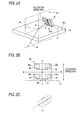
- Figs. 2A to 2C are views illustrating an arrangement of the high-frequency sensor 30 of the urinal 10 according to this embodiment, where Fig. 2A is a schematic perspective view, Fig. 2B is a schematic top view showing the patch antenna, and Fig. 2C is a view showing the radio beam.
- the high-frequency sensor 30 is disposed on the upper surface 12a of the ceramic ware or the like.
- the high-frequency sensor 30 is disposed such that an intersection angle formed between the upper surface 12a and the radiation surface 32a of the patch antenna 32 is set to the angle ⁇ .
- the radio beam 14 radiated from the patch antenna 32 generates a transmitted beam and a reflected beam at the upper surface 12a.
- FIG. 2B As shown in Fig. 2B , four feed elements 32c are arranged on both sides of the line A-A and the line B-B.
- a center point 36 corresponding to an intersection point where the line A-A intersects with the line B-B is almost a center point of the patch antenna 32 and a radiation center of the radio beam 14.
- Each feeding point 35 is connected to an oscillator so that the radio beam 14 is excited.
- the excitation direction of the radio beam 14 is located at the radiation surface 32a so as to be parallel to the line A-A indicated by the arrow.
- the radiation pattern of the radio beam 14 spreading in space can be controlled by changing an arrangement of the four feed elements 32c.
- a surface perpendicular to the radiation surface 32a and perpendicular to the upper surface 12a via the center point 36 is referred to as an incident surface 40.
- the radio beam 14 radiated from the vicinity of the center point 36 generates a transmitted beam passing through the upper surface 12a as a transmission surface so as to be transmitted to a medium such as earthenware constituting the urinal body 12 and a reflected beam reflected by the upper surface 12a as a reflection surface.
- the radiation pattern of the radio beam 14 is controlled by the four feed elements 32c.
- the configuration of the patch antenna 32 is not limited thereto.
- Figs. 3A to 3C show an arrangement of the high-frequency sensor in a case where the excitation direction is substantially perpendicular to the incident surface 40, where Fig. 3A is a schematic perspective view and Fig. 3B is a schematic top view showing a patch antenna.
- a simulation frequency is 10.525 GHz.
- an intersection angle ⁇ formed between the excitation direction and the cross line 17 in which a plane including the radiation surface 32a intersects with the upper surface 12a or the rear surface 12b of the urinal body 12 substantially forms a right angle.
- the radiation surface 32a may not directly contact with the upper surface 12a or the rear surface 12b.
- Fig. 4A shows a case where a plane including the radiation surface 32a intersects with the upper surface 12a or a plane including the radiation surface 32a intersects with the rear surface 12b.
- Fig. 4B shows a case where a plane including the radiation surface 32a intersects with a plane including the upper surface 12a or a plane including the radiation surface 32a intersects with a plane including the rear surface 12b.
- the radio beam 14 in the incident surface 40 includes an incident beam 42, a transmitted beam 44, and a reflected beam 46. That is, the incident beam 42 is divided into a component forming the transmitted beam 44 refracted by a difference in relative permittivity between air and the urinal body 12 and a component forming the reflected beam 46 reflected at the upper surface 12a or the rear surface 12b.
- a transmissivity of Fig. 6A is larger than that of Fig. 6B.
- Fig. 6B shows a case where a reflectivity of the urinal body 12 is large.
- the reflectivity becomes larger, so that the radiation intensity of the transmitted beam 44 becomes smaller than that of Fig. 7A and detection sensitivity becomes smaller.
- Each transmissivity becomes smaller than that in
- the transmitted beam 44 hardly exists, and it is difficult to detect the object.
- an attachment place of the high-frequency sensor 30 is determined in advance depending on the urinal. In the urinal 10, by appropriately selecting the angle ⁇ , it is possible to radiate the radio beam to the object with high precision.
- Figs. 9A to 9F are sectional views showing the radiation pattern in the incident surface 40 when the angle ⁇ formed between the excitation direction of the radio beam 14 and the cross line 17 is changed.
- the angle ⁇ formed between the excitation direction and the cross line 17 is set so that the intensity of the transmitted beam 44 is larger than that of the reflected beam 46, it is possible to increase the transmissivity of the radio beam 14 toward the object. With such a configuration, it is possible to facilitate the detection in the low-output radio beam.
- the radio wave radiation surface of the high-frequency sensor is inclined with respect to a surface of a dielectric material and the excitation direction of the radio wave is adjusted, it is possible to restrict the reflection of the radio wave at the surface of the dielectric body. As a result, it is possible to surely detect a user or the like in front of the urinal. Also, it is possible to prevent the erroneous detection caused by the reflected radio beam.
- Fig. 10A is a schematic sectional view showing the urinal 10 according to the first embodiment.
- the intersection angle ⁇ formed between the radiation surface 32a and the upper surface 12a is in a range of more than 0 degree to less than 90 degree.
- a concave portion is provided in the upper portion of the urinal body 12 made of earthenware so as to accommodate the high-frequency sensor 30, and the high-frequency sensor 30 is disposed so as to form the intersection angle ⁇ with respect to a bottom surface of the concave portion corresponding to the upper surface 12a.
- a direction of the radio beam 14 is optimally set so as to face the human body 50, and is capable of detecting a flow of urine.
- a disturbance such as a human body passing a space in the vicinity of the urinal or a noise of a fluorescent lamp may cause an influence.
- Fig. 10B is a schematic sectional view showing the urinal 10 according to a modified example of the first embodiment.
- a direction of the maximum radiation intensity of the radio beam 14 is substantially identical with a line connecting a center 12c of a lip front end of the urinal body 12 and the center point 36 of the antenna. With such a configuration, it is possible to detect the human body and the flow of urine with high precision.
- the center 12c is set to be located near the center of a lower portion of the urinal body 12 in a horizontal direction.
- Fig. 11 is a schematic sectional view showing the urinal 10 according to the second embodiment.
- the front end portion of the radio beam 14 faces the rear surface 12b of the urinal body 12. Since the radio beam 14 faces the flow of urine, it is possible to optimally detect the flow of urine and to optimally restrict an influence of the disturbance. Meanwhile, since the radio beam 14 does not face the human body, sensitivity for detecting the human body may be insufficient.
- Fig. 12A is a schematic sectional view showing the urinal 10 according to the third embodiment.
- the high-frequency sensor 30 is disposed so as to form the intersection angle ⁇ with respect to the rear surface 12b.
- the intersection angle ⁇ is preferably in a range of more than 0 degree to less than 90 degree, and more preferably in a range of more than 0 degree to 60 degree. With such a configuration, it is optimally detect the flow of urine and to detect the human body without being influenced by the disturbance.
- the rear surface 12b corresponds to a rear surface side of the urinal body 12 which is opposite to the human body.
- Fig. 12B is a schematic view showing a modified example of the third embodiment.
- a direction of the maximum radiation intensity of the radio beam 14 is substantially identical with a line connecting a center 12c of a lip front end of the urinal body 12 and the center point 36 of the antenna, thereby detecting the flow of urine and the human body with high precision.
- Fig. 13A is a schematic view showing the urinal 10 according to the fourth embodiment in a case where the maximum intensity direction is inclined with respect to a normal line of the radiation surface 32a and the angle ⁇ > 0 degree.
- the angle ⁇ is smaller than that of the third embodiment. Therefore, the urinal can be reduced in thickness by reducing a space of the rear surface 12b.
- the intersection angle ⁇ is larger than 30 degree, a gain of the antenna decreases and a radiation power decreases. As a result, it is difficult to maintain high precision upon detecting the flow of urine and the human body.
- the intersection angle ⁇ is preferably in a range of 0 to 30 degree.
- Fig. 14 is a schematic sectional view showing the urinal 10 according to a fifth embodiment.
- the high-frequency sensor 30 is located at a position in the vicinity of a height of the center 12c and is inclined at the intersection angle ⁇ with respect to the rear surface 12b so that the radio beam 14 is radiated upward.
- the intersection angle ⁇ is large, it is possible to increase the transmissivity of the radio beam 14. Particularly, it is possible to improve precision upon detecting the flow of urine.
- the angle ⁇ formed between the radiation surface 32a and the upper surface 12a of the urinal body 12 or the angle ⁇ formed between the radiation surface 32a and the rear surface 12b is set in a range of more than 0 degree to less than 90 degree.
- the intersection angle ⁇ formed between the excitation direction and the cross line 17 is set so that the intensity of the radio beam 14 passing through the urinal body 12 is larger than that of the reflected beam 46 reflected by the upper surface 12a or the rear surface 12b.
- the present invention is not limited to the exemplary embodiments, but the shape, the size, the material, and the arrangement relationship of the urinal body, the antenna, and the high-frequency sensor constituting the urinal may be modified by the person skilled in the art without departing from the spirit of the present invention.
Landscapes
- Engineering & Computer Science (AREA)
- Life Sciences & Earth Sciences (AREA)
- Remote Sensing (AREA)
- Health & Medical Sciences (AREA)
- Hydrology & Water Resources (AREA)
- Public Health (AREA)
- Water Supply & Treatment (AREA)
- Physics & Mathematics (AREA)
- Electromagnetism (AREA)
- Aviation & Aerospace Engineering (AREA)
- Environmental & Geological Engineering (AREA)
- Geology (AREA)
- General Life Sciences & Earth Sciences (AREA)
- General Physics & Mathematics (AREA)
- Geophysics (AREA)
- Sanitary Device For Flush Toilet (AREA)
- Radar Systems Or Details Thereof (AREA)
- Geophysics And Detection Of Objects (AREA)
Abstract
Description
- The present invention relates to a urinal, and more particularly, to a urinal having a high-frequency sensor.
- When a human body and a liquid flow are detected with high precision using a Doppler frequency signal from a high-frequency sensor to control an opening and closing of a valve at an appropriate timing, a urinal can be used without wasting cleaning water. Also, when an antenna of the high-frequency sensor is configured by patch electrodes, it is possible to facilitate a decrease in size of the high-frequency sensor.
- In the related art, there has been known a urinal cleaning device which controls an opening and closing of a valve provided in a water supply pipe (see e.g., Patent Document 1). In the related art, a liquid flow state in a bowl interior space is calculated based on a Doppler frequency corresponding to a difference between a transmitted wave and a received wave, thereby controlling the valve.
- In the urinal, in order to detect a human body or a flow of urine with a low emission power while restraining an erroneous detection, it is necessary to control a direction of a radio beam with high precision. However, there is a limitation upon changing a direction of a radio beam just by controlling an arrangement or a phase of the patch electrodes. When an intersection angle between a radiation surface of the patch antenna and a urinal body is adjusted, it is possible to easily change a direction of the radio beam. In this case, a transmissivity of a dielectric medium decreases due to an excitation direction, and thus a problem arises in that the radio beam cannot be transmitted to an object with a high transmissivity.
- Also, Patent Document 2 discloses a urinal in which a radio frequency sensor is placed on a rear upper surface of a urinal body and the radio frequency sensor is configured to radiate a radio beam obliquely. However, according to the configuration of the related art, the radio beam radiated from the radio frequency sensor is reflected at the boundary between the urinal body and an air. Accordingly, in order to detect a human body or a flow of urine, it is necessary to provide a reflector, which is used for reflecting the radio beam reflected at the boundary between the urinal and the air again, over the radio frequency sensor. Thus, since the reflector must be newly provided in the urinal, there is a problem in that design of the urinal is limited.
- [Patent Document 1] Japanese Patent No.
3740696 - [Patent Document 2] Japanese Unexamined Patent Publication No.
2005-290718 - According to the present invention, it is an object to provide a urinal including a high-frequency sensor capable of radiating the radio beam to the object with high precision, and by which transmissivity in a dielectric material can be enhanced.
- According to an exemplary embodiment of the present invention, there is provided a urinal. A urinal includes: a urinal body; a high-frequency sensor which radiates a radio beam obliquely passing through an upper surface of the urinal body toward a bowl and receives a reflected wave from an object so as to generate a detection signal; and a valve which discharges or stops flushing water to the urinal body in response to the detection signal. An angle formed between a first plane including the upper surface of the urinal body and a second plane including a radiation surface of an antenna of the high-frequency sensor is in a range of more than 0 degree to less than 90 degree. A cross line where the first plane and the second plane intersect with each other is substantially parallel to a horizontal direction of the urinal body. The radio beam is a linearly-polarized wave. An excitation direction of the radio beam intersects with the cross line, and an intensity of the radio beam passing through the urinal body is larger than that of the radio beam reflected by the upper surface.
- According to another exemplary embodiment of the present invention, there is provided a urinal. A urinal includes: a urinal body; a high-frequency sensor which radiates a radio beam obliquely passing through a rear surface of the urinal body toward a bowl and receives a reflected wave from an object so as to generate a detection signal; and a valve which discharges or stops flushing water to the urinal body in response to the detection signal. An angle formed between a first plane including the rear surface of the urinal body and a second plane including a radiation surface of an antenna of the high-frequency sensor is in a range of more than 0 degree to less than 90 degree. A cross line where the first plane and the second plane intersect with each other is substantially parallel to a horizontal direction of the urinal body. The radio beam is a linearly-polarized wave. An excitation direction of the radio beam intersects with the cross line, and an intensity of the radio beam passing through the urinal body is larger than that of the radio beam reflected by the rear surface.
-
-
Fig. 1 is a view illustrating a configuration of a urinal; -
Figs. 2A to 2C are views illustrating an arrangement of a high-frequency sensor in a case where an excitation direction is substantially parallel to an incident surface; -
Figs. 3A to 3C are views illustrating the arrangement of the high-frequency sensor in a case where the excitation direction is substantially perpendicular to the incident surface; -
Figs. 4A and 4B are schematic sectional view illustrating a case where a radiation surface does not directly contact with a surface; -
Figs. 5A and 5B are sectional views illustrating an emission pattern in a simulation case of an angle α = 0 degree; -
Figs. 6A and 6B are sectional views illustrating an emission pattern in the incident surface in the simulation; -
Figs. 7A and 7B are sectional views illustrating the emission pattern in the incident surface in the simulation; -
Figs. 8A and 8B are sectional views illustrating the emission pattern in the incident surface in the simulation; -
Figs. 9A to 9F are sectional views illustrating the emission pattern in the incident surface in the simulation; -
Figs. 10A and 10B are schematic sectional views illustrating the urinal according to a first embodiment; -
Fig. 11 is a schematic sectional view illustrating the urinal according to a second embodiment; -
Figs. 12A to 12C are schematic sectional views illustrating the urinal according to a third embodiment; -
Figs. 13A and 13B are schematic sectional views illustrating the urinal according to a fourth embodiment; and -
Fig. 14 is a schematic sectional view illustrating the urinal according to a fifth embodiment. -
- 10
- urinal
- 12
- urinal body
- 12a
- upper surface
- 12b
- rear surface
- 12c
- center of lip front
- 14
- radio beam
- 17
- cross line
- 18
- valve
- 30
- high-frequency sensor
- 32
- patch antenna
- 32a
- radiation surface
- 36
- center point
- Hereinafter, exemplary embodiments of the present invention will be described with reference to the accompanying drawings.
Fig. 1 is a view illustrating a configuration of a urinal according to an embodiment of the present invention. Aurinal body 12 is made of, e.g., earthenware (relative permittivity: εr), and has anupper surface 12a and arear surface 12b. A high-frequency sensor 30 is disposed on theupper surface 12a or therear surface 12b, and radiates aradio beam 14. A radiation pattern of the high-frequency sensor 30 is controlled, and the high-frequency sensor 30 inputs a Doppler frequency signal corresponding to a difference frequency between a transmitted frequency and a reflected frequency reflected from an object, to acontrol part 16. Thecontrol part 16 outputs an ON/OFF signal, and controls an opening and closing of avalve 18 so as to discharge or stop flushingwater 19. - The high-
frequency sensor 30 is relatively fixed to theurinal body 12, and radiates theradio beam 14 passing through theurinal body 12 to a bowl. In this case, when theupper surface 12a is substantially parallel to a radiation surface of an antenna, theradio beam 14 is radiated in a direction substantially perpendicular to theradiation surface 32a of the antenna, and theradio beam 14 substantially faces the downside in a vertical direction. In this case, a shake of seal water filled in the bowl of theurinal body 12 may be erroneously detected as the frequency of the Doppler signal from a human body.
Meanwhile, when the radiation surface of the antenna is substantially parallel to therear surface 12b, theradio beam 14 faces a horizontal direction. In this case, a disturbance such as a human body passing by theurinal body 12 or a noise of a fluorescent lamp may be easily detected. - In this embodiment, a plane including the incident surface of the
urinal body 12 to which the radio wave radiated from the antenna is incident and a plane including the radiation surface of the antennal intersect with each other in an cross line in an angular range of 0 to 90 degree. Then, an excitation direction of the radio beam is set to be substantially perpendicular to the cross line.
Specifically, an angle α formed between theupper surface 12a of theurinal body 12 and theradiation surface 32a of the antenna or an angle α formed between therear surface 12b and theradiation surface 32a is set in a range of more than 0 degree to less than 90 degree. Ancross line 17 formed between theupper surface 12a and theradiation surface 32a or thecross line 17 formed between therear surface 12b and theradiation surface 32a is set to be substantially parallel to a horizontal direction of theurinal body 12, which is indicated by the arrow. That is, the angle α is maintained so that a gap formed between theradiation surface 32a and theupper surface 12a or a gap formed between theradiation surface 32a and therear surface 12b is substantially identical with the horizontal direction of theurinal body 12. With such a configuration, it is possible to reduce an influence of the disturbance and the erroneous detection. In addition, theradio beam 14 is easily allowed to face a direction substantially perpendicular to the horizontal direction of theurinal body 12, and thus it is possible to restrict interference between a plurality of urinals arranged in rows, thereby improving a detection precision upon detecting the object. -
Figs. 2A to 2C are views illustrating an arrangement of the high-frequency sensor 30 of theurinal 10 according to this embodiment, whereFig. 2A is a schematic perspective view,Fig. 2B is a schematic top view showing the patch antenna, andFig. 2C is a view showing the radio beam.
The high-frequency sensor 30 is disposed on theupper surface 12a of the ceramic ware or the like. The high-frequency sensor 30 is disposed such that an intersection angle formed between theupper surface 12a and theradiation surface 32a of thepatch antenna 32 is set to the angle α. Theradio beam 14 radiated from thepatch antenna 32 generates a transmitted beam and a reflected beam at theupper surface 12a. In addition, the same applies to therear surface 12b as well as theupper surface 12a. - As shown in
Fig. 2B , fourfeed elements 32c are arranged on both sides of the line A-A and the line B-B. Acenter point 36 corresponding to an intersection point where the line A-A intersects with the line B-B is almost a center point of thepatch antenna 32 and a radiation center of theradio beam 14. Eachfeeding point 35 is connected to an oscillator so that theradio beam 14 is excited. The excitation direction of theradio beam 14 is located at theradiation surface 32a so as to be parallel to the line A-A indicated by the arrow. By using such apatch antenna 32, it is possible to easily generate an excitation of a linearly-polarized wave. - As shown in
Fig. 2C , the radiation pattern of theradio beam 14 spreading in space can be controlled by changing an arrangement of the fourfeed elements 32c. InFig. 2A , a surface perpendicular to theradiation surface 32a and perpendicular to theupper surface 12a via thecenter point 36 is referred to as anincident surface 40. Theradio beam 14 radiated from the vicinity of thecenter point 36 generates a transmitted beam passing through theupper surface 12a as a transmission surface so as to be transmitted to a medium such as earthenware constituting theurinal body 12 and a reflected beam reflected by theupper surface 12a as a reflection surface. - In addition, in the embodiment shown in
Fig. 2B , the radiation pattern of theradio beam 14 is controlled by the fourfeed elements 32c. However, the configuration of thepatch antenna 32 is not limited thereto. - Next, a case will be described in which the
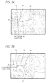
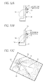
radio beam 14 changes depending on the intersection angle α formed between theradiation surface 32a and theupper surface 12a or therear surface 12b when theurinal body 12 is made of earthenware having εr = 4.15 in terms of a simulation.Figs. 3A to 3C show an arrangement of the high-frequency sensor in a case where the excitation direction is substantially perpendicular to theincident surface 40, whereFig. 3A is a schematic perspective view andFig. 3B is a schematic top view showing a patch antenna. In addition, a simulation frequency is 10.525 GHz. In the following simulation, an intersection angle β formed between the excitation direction and thecross line 17 in which a plane including theradiation surface 32a intersects with theupper surface 12a or therear surface 12b of theurinal body 12 substantially forms a right angle. In addition, theradiation surface 32a may not directly contact with theupper surface 12a or therear surface 12b.Fig. 4A shows a case where a plane including theradiation surface 32a intersects with theupper surface 12a or a plane including theradiation surface 32a intersects with therear surface 12b.Fig. 4B shows a case where a plane including theradiation surface 32a intersects with a plane including theupper surface 12a or a plane including theradiation surface 32a intersects with a plane including therear surface 12b. - Even when the angle β is not at 90 degree, the simulation result may be applied to components perpendicular to the
cross line 17. Theradio beam 14 in theincident surface 40 includes anincident beam 42, a transmittedbeam 44, and a reflectedbeam 46. That is, theincident beam 42 is divided into a component forming the transmittedbeam 44 refracted by a difference in relative permittivity between air and theurinal body 12 and a component forming the reflectedbeam 46 reflected at theupper surface 12a or therear surface 12b. -
Figs. 5A and 5B are sectional views showing the radiation pattern in theincident surface 40 in terms of a simulation in a case of angle α = 0 degree, that is, theradiation surface 32a is parallel to theupper surface 12a or therear surface 12b without being inclined, whereFig. 5A shows a case where the excitation direction is substantially parallel to theincident surface 40 andFig. 5B shows a case where the excitation direction is substantially perpendicular to theincident surface 40. Curved lines shown inFigs. 5A and 5B are obtained by connecting the points having the same radiation intensity of theradio beam 14, and the outermost curved line has the lowest radiation intensity. In any case, theradio beam 14 easily passes through theurinal body 12, and a large difference does not occur in the transmission power. However, it may not be supposed that the object exists at this position. In this case, when theradiation surface 32a is inclined with respect to theupper surface 12a or therear surface 12b, it is possible to efficiently radiate theradio beam 14 to the object. -
Figs. 6A and 6B are sectional views showing the radiation pattern in theincident surface 40 in terms of a simulation in a case of the angle α = 30 degree, whereFig. 6A shows a case where the excitation direction is substantially parallel to theincident surface 40 andFig. 6B shows a case where the excitation direction is substantially perpendicular to theincident surface 40. A transmissivity ofFig. 6A is larger than that ofFig. 6B. Fig. 6B shows a case where a reflectivity of theurinal body 12 is large. -
Figs. 7A and 7B are sectional views showing the radiation pattern in theincident surface 40 in terms of a simulation in a case of the angle α = 45 degree, whereFig. 7A shows a case where the excitation direction is substantially parallel to theincident surface 40 andFig. 7B shows a case where the excitation direction is substantially perpendicular to theincident surface 40. Each transmissivity becomes smaller than that in a case where the angle α = 30 degree. Particularly, inFig. 7B , the reflectivity becomes larger, so that the radiation intensity of the transmittedbeam 44 becomes smaller than that ofFig. 7A and detection sensitivity becomes smaller.Figs. 8A and 8B are sectional views showing the radiation pattern in theincident surface 40 in terms of a simulation in a case of the angle α = 60 degree, whereFig. 8A shows a case where the excitation direction is substantially parallel to theincident surface 40 andFig. 8B shows a case where the excitation direction is substantially perpendicular to theincident surface 40. Each transmissivity becomes smaller than that that in a case of the angle α = 45 degree. Particularly, inFig.8B , the transmittedbeam 44 hardly exists, and it is difficult to detect the object. In general, an attachment place of the high-frequency sensor 30 is determined in advance depending on the urinal. In theurinal 10, by appropriately selecting the angle α, it is possible to radiate the radio beam to the object with high precision. That is,Figs. 9A to 9F are sectional views showing the radiation pattern in theincident surface 40 when the angle β formed between the excitation direction of theradio beam 14 and thecross line 17 is changed. At this time,Fig. 9A shows a case where the angle β = 80 degree,Fig. 9B shows a case of the angle β = 75 degree,Fig. 9C shows a case where the angle β = 60 degree,Fig. 9D shows a case where the angle β = 55 degree,Fig. 9E shows a case where the angle β = 50 degree, andFig. 9 shows a case where the angle β = 45 degree, respectively, where the angle α formed between a plane including theradiation surface 32a of theantenna 32 and theupper surface 12a or therear surface 12b of theurinal body 12 is set to 45 degree. - The transmitted
beam 44 passing through theurinal body 12 becomes maximum when the angle β = 90 degree, and its intensity becomes smaller as the angle β becomes smaller. Meanwhile, the reflected beam 46 (indicated by the dashed line) in theupper surface 12a or therear surface 12b becomes larger as the angle β becomes smaller. From the analysis result, it is understood that the intensity of the reflectedbeam 46 is larger than that of the transmittedbeam 44 when the angle β is 55 degree or more. In this embodiment, when the angle β formed between the excitation direction and thecross line 17 is set so that the intensity of the transmittedbeam 44 is larger than that of the reflectedbeam 46, it is possible to increase the transmissivity of theradio beam 14 toward the object. With such a configuration, it is possible to facilitate the detection in the low-output radio beam. - For example, in a case of a public toilet in which a plurality of urinals are arranged in rows, it is necessary to provide the high-frequency sensor on the rear surface side of each urinal. In this case, when the radio wave radiated from the high-frequency sensor is reflected by the rear surface of the urinal made of earthenware, this reflection influences the other adjacent high-frequency sensors, and thus an erroneous detection may occur due to an interference of the radio wave.
- On the contrary, according to this embodiment, when the radio wave radiation surface of the high-frequency sensor is inclined with respect to a surface of a dielectric material and the excitation direction of the radio wave is adjusted, it is possible to restrict the reflection of the radio wave at the surface of the dielectric body. As a result, it is possible to surely detect a user or the like in front of the urinal. Also, it is possible to prevent the erroneous detection caused by the reflected radio beam.
-
Fig. 10A is a schematic sectional view showing theurinal 10 according to the first embodiment. The high-frequency sensor 30 is set such that the angle β = 90 degree inFig. 1 and the excitation direction is parallel to theincident surface 40. In addition, the intersection angle α formed between theradiation surface 32a and theupper surface 12a is in a range of more than 0 degree to less than 90 degree. When a direction of the maximum radiation intensity of theradio beam 14 in theincident surface 40 is substantially perpendicular to theradiation surface 32a, a direction of theradio beam 14 generated from the high-frequency sensor 30 disposed on the upper portion of theurinal body 12 faces ahuman body 50. - For example, a concave portion is provided in the upper portion of the
urinal body 12 made of earthenware so as to accommodate the high-frequency sensor 30, and the high-frequency sensor 30 is disposed so as to form the intersection angle α with respect to a bottom surface of the concave portion corresponding to theupper surface 12a. In this embodiment, a direction of theradio beam 14 is optimally set so as to face thehuman body 50, and is capable of detecting a flow of urine. Meanwhile, a disturbance such as a human body passing a space in the vicinity of the urinal or a noise of a fluorescent lamp may cause an influence. -
Fig. 10B is a schematic sectional view showing theurinal 10 according to a modified example of the first embodiment. A direction of the maximum radiation intensity of theradio beam 14 is substantially identical with a line connecting acenter 12c of a lip front end of theurinal body 12 and thecenter point 36 of the antenna. With such a configuration, it is possible to detect the human body and the flow of urine with high precision. In addition, thecenter 12c is set to be located near the center of a lower portion of theurinal body 12 in a horizontal direction. -
Fig. 11 is a schematic sectional view showing theurinal 10 according to the second embodiment. The front end portion of theradio beam 14 faces therear surface 12b of theurinal body 12. Since theradio beam 14 faces the flow of urine, it is possible to optimally detect the flow of urine and to optimally restrict an influence of the disturbance. Meanwhile, since theradio beam 14 does not face the human body, sensitivity for detecting the human body may be insufficient. -
Fig. 12A is a schematic sectional view showing theurinal 10 according to the third embodiment. The high-frequency sensor 30 is disposed so as to form the intersection angle α with respect to therear surface 12b. The intersection angle α is preferably in a range of more than 0 degree to less than 90 degree, and more preferably in a range of more than 0 degree to 60 degree. With such a configuration, it is optimally detect the flow of urine and to detect the human body without being influenced by the disturbance. In addition, as shown inFig. 1 , therear surface 12b corresponds to a rear surface side of theurinal body 12 which is opposite to the human body.Fig. 12B is a schematic view showing a modified example of the third embodiment. A direction of the maximum radiation intensity of theradio beam 14 is substantially identical with a line connecting acenter 12c of a lip front end of theurinal body 12 and thecenter point 36 of the antenna, thereby detecting the flow of urine and the human body with high precision. -
Fig. 12C is a sectional view showing the radiation pattern according to the modified example of the third embodiment, where a maximum intensity direction of the radiation pattern is substantially perpendicular to theradiation surface 32a in a case where the angle α = 60 degree. -
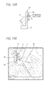
Fig. 13A is a schematic view showing theurinal 10 according to the fourth embodiment in a case where the maximum intensity direction is inclined with respect to a normal line of theradiation surface 32a and the angle α > 0 degree. In addition,Fig. 13B is a sectional view showing the radiation pattern in a case where the angle α = 30 degree and an intersection angle γ formed between the normal line of theradiation surface 32a and the maximum intensity direction is 30 degree. In this embodiment, the angle α is smaller than that of the third embodiment. Therefore, the urinal can be reduced in thickness by reducing a space of therear surface 12b. However, when the intersection angle γ is larger than 30 degree, a gain of the antenna decreases and a radiation power decreases. As a result, it is difficult to maintain high precision upon detecting the flow of urine and the human body. For this reason, the intersection angle γ is preferably in a range of 0 to 30 degree. -
Fig. 14 is a schematic sectional view showing theurinal 10 according to a fifth embodiment. The high-frequency sensor 30 is located at a position in the vicinity of a height of thecenter 12c and is inclined at the intersection angle α with respect to therear surface 12b so that theradio beam 14 is radiated upward. When the intersection angle α is large, it is possible to increase the transmissivity of theradio beam 14. Particularly, it is possible to improve precision upon detecting the flow of urine. - In the first to fifth embodiments, the angle α formed between the
radiation surface 32a and theupper surface 12a of theurinal body 12 or the angle α formed between theradiation surface 32a and therear surface 12b is set in a range of more than 0 degree to less than 90 degree. In addition, the intersection angle β formed between the excitation direction and thecross line 17 is set so that the intensity of theradio beam 14 passing through theurinal body 12 is larger than that of the reflectedbeam 46 reflected by theupper surface 12a or therear surface 12b. With such a configuration, it is possible to easily allow thetransmitting beam 44 to correctly face the object, and thus to increase the transmissivity of theradio beam 14. Also, it is possible to restrict an influence of the disturbance using the low-output radio beam 14, and thus to provide theurinal 10 capable of detecting the object with high precision. - As described above, the exemplary embodiments of the invention have been described with reference to the accompanying drawings. However, the present invention is not limited to the exemplary embodiments, but the shape, the size, the material, and the arrangement relationship of the urinal body, the antenna, and the high-frequency sensor constituting the urinal may be modified by the person skilled in the art without departing from the spirit of the present invention.
Claims (8)
- A urinal comprising:a urinal body;a high-frequency sensor which radiates a radio beam obliquely passing through an upper surface of the urinal body toward a bowl and receives a reflected wave from an object so as to generate a detection signal; anda valve which discharges or stops flushing water to the urinal body in response to the detection signal,wherein an angle formed between a first plane including the upper surface of the urinal body and a second plane including a radiation surface of an antenna of the high-frequency sensor is in a range of more than 0 degree to less than 90 degree,wherein a cross line where the first plane and the second plane intersect with each other is substantially parallel to a horizontal direction of the urinal body,wherein the radio beam is a linearly-polarized wave,wherein an excitation direction of the radio beam intersects with the cross line, andwherein an intensity of the radio beam passing through the urinal body is larger than that of the radio beam reflected by the upper surface.
- The urinal according to Claim 1, wherein the excitation direction is substantially perpendicular to the cross line.
- The urinal according to Claim 1, wherein a direction of the maximum intensity of the radio beam is substantially identical with a line connecting a center point of the antenna and a center of a lip front end of the urinal body.
- The urinal according to Claim 2, wherein a direction of the maximum intensity of the radio beam is substantially identical with a line connecting a center point of the antenna and a center of a lip front end of the urinal body.
- A urinal comprising:a urinal body;a high-frequency sensor which radiates a radio beam obliquely passing through a rear surface of the urinal body toward a bowl and receives a reflected wave from an object so as to generate a detection signal; anda valve which discharges or stops flushing water to the urinal body in response to the detection signal,wherein an angle formed between a first plane including the rear surface of the urinal body and a second plane including a radiation surface of an antenna of the high-frequency sensor is in a range of more than 0 degree to less than 90 degree,wherein a cross line where the first plane and the second plane intersect with each other is substantially parallel to a horizontal direction of the urinal body,wherein the radio beam is a linearly-polarized wave,wherein an excitation direction of the radio beam intersects with the cross line, andwherein an intensity of the radio beam passing through the urinal body is larger than that of the radio beam reflected by the rear surface.
- The urinal according to Claim 5, wherein the excitation direction is substantially perpendicular to the cross line.
- The urinal according to Claim 5, wherein a direction of the maximum intensity of the radio beam is substantially identical with a line connecting a center point of the antenna and a center of a lip front end of the urinal body.
- The urinal according to Claim 6, wherein a direction of the maximum intensity of the radio beam is substantially identical with a line connecting a center point of the antenna and a center of a lip front end of the urinal body.
Applications Claiming Priority (2)
| Application Number | Priority Date | Filing Date | Title |
|---|---|---|---|
| JP2007184566A JP4117688B1 (en) | 2007-07-13 | 2007-07-13 | Urinal equipment |
| PCT/JP2008/001847 WO2009011109A1 (en) | 2007-07-13 | 2008-07-10 | Urine bowl device |
Publications (2)
| Publication Number | Publication Date |
|---|---|
| EP2166164A1 true EP2166164A1 (en) | 2010-03-24 |
| EP2166164A4 EP2166164A4 (en) | 2016-12-14 |
Family
ID=39704883
Family Applications (1)
| Application Number | Title | Priority Date | Filing Date |
|---|---|---|---|
| EP08790199.7A Withdrawn EP2166164A4 (en) | 2007-07-13 | 2008-07-10 | Urine bowl device |
Country Status (6)
| Country | Link |
|---|---|
| US (1) | US8250680B2 (en) |
| EP (1) | EP2166164A4 (en) |
| JP (1) | JP4117688B1 (en) |
| CN (1) | CN101548055B (en) |
| TW (1) | TWI438324B (en) |
| WO (1) | WO2009011109A1 (en) |
Cited By (2)
| Publication number | Priority date | Publication date | Assignee | Title |
|---|---|---|---|---|
| EP3486382A1 (en) * | 2017-11-15 | 2019-05-22 | Geberit International AG | Actuation device for a sanitary device |
| WO2021051167A1 (en) * | 2019-09-20 | 2021-03-25 | Caroma Industries Limited | Urinal system, water consumer system having a urinal system, and method for operating a urinal system |
Families Citing this family (6)
| Publication number | Priority date | Publication date | Assignee | Title |
|---|---|---|---|---|
| CA2866674C (en) | 2012-03-07 | 2019-04-30 | Moen Incorporated | Electronic plumbing fixture fitting |
| TWI547622B (en) * | 2013-07-16 | 2016-09-01 | 許今彥 | Intelligent urination device with multiple sensing fields |
| JP6455018B2 (en) * | 2014-08-21 | 2019-01-23 | Toto株式会社 | Water discharge device |
| JP6656587B2 (en) * | 2016-03-23 | 2020-03-04 | Toto株式会社 | Water surrounding equipment |
| US10519642B2 (en) * | 2017-04-26 | 2019-12-31 | Masco Canada Limited | Adjustable sensor device for a plumbing fixture |
| WO2022070113A1 (en) * | 2020-09-29 | 2022-04-07 | Olive Diagnostics Ltd. | Home toilet system for monitoring urine components in real time while urination |
Family Cites Families (13)
| Publication number | Priority date | Publication date | Assignee | Title |
|---|---|---|---|---|
| CN2239457Y (en) * | 1994-10-17 | 1996-11-06 | 万继领 | Self-control flushing urinating device |
| US6212697B1 (en) * | 1999-09-07 | 2001-04-10 | Arichell Technologies, Inc. | Automatic flusher with bi-modal sensitivity pattern |
| JP4363803B2 (en) * | 2000-08-02 | 2009-11-11 | パナソニック株式会社 | Method for exciting circular array antenna and radio apparatus using the method |
| JP2002285626A (en) * | 2001-03-22 | 2002-10-03 | Toto Ltd | Urinal |
| EP1428947B1 (en) | 2001-08-30 | 2009-03-25 | Toto Ltd. | Flushing device with motion sensor |
| US6619614B2 (en) * | 2001-12-04 | 2003-09-16 | Arichell Technologies, Inc. | Automatic flow controller employing energy-conservation mode |
| EP1466118A4 (en) * | 2001-12-26 | 2008-11-12 | Arichell Tech Inc | Bathroom flushers with novel sensors and controllers |
| JP2005274406A (en) * | 2004-03-25 | 2005-10-06 | Toto Ltd | Object detector, and equipments for kitchens and sanitary spaces provided with object detector |
| JP4168446B2 (en) | 2004-03-31 | 2008-10-22 | Toto株式会社 | urinal |
| CN1683723A (en) * | 2004-04-12 | 2005-10-19 | 王立国 | Two purpose indoor urinary device for washing hand and toilet flushing |
| JP4063247B2 (en) * | 2004-05-14 | 2008-03-19 | Toto株式会社 | Urinal equipment |
| CN1724822A (en) * | 2004-07-21 | 2006-01-25 | 王立国 | Intelligent gesture sensing hand washing and flushing dual purpose indoor urinal (II) |
| JP2006287766A (en) * | 2005-04-04 | 2006-10-19 | Toto Ltd | Radio wave transmission antenna and object sensor |
-
2007
- 2007-07-13 JP JP2007184566A patent/JP4117688B1/en active Active
-
2008
- 2008-07-10 CN CN2008800009494A patent/CN101548055B/en not_active Expired - Fee Related
- 2008-07-10 EP EP08790199.7A patent/EP2166164A4/en not_active Withdrawn
- 2008-07-10 WO PCT/JP2008/001847 patent/WO2009011109A1/en not_active Ceased
- 2008-07-11 US US12/172,176 patent/US8250680B2/en not_active Expired - Fee Related
- 2008-07-11 TW TW097126463A patent/TWI438324B/en not_active IP Right Cessation
Non-Patent Citations (1)
| Title |
|---|
| See references of WO2009011109A1 * |
Cited By (6)
| Publication number | Priority date | Publication date | Assignee | Title |
|---|---|---|---|---|
| EP3486382A1 (en) * | 2017-11-15 | 2019-05-22 | Geberit International AG | Actuation device for a sanitary device |
| US10697163B2 (en) | 2017-11-15 | 2020-06-30 | Geberit International Ag | Actuating device |
| WO2021051167A1 (en) * | 2019-09-20 | 2021-03-25 | Caroma Industries Limited | Urinal system, water consumer system having a urinal system, and method for operating a urinal system |
| GB2602587A (en) * | 2019-09-20 | 2022-07-06 | Caroma Industries Ltd | Urinal system, water consumer system having a urinal system, and method for operating a urinal system |
| GB2602587B (en) * | 2019-09-20 | 2023-12-20 | Caroma Industries Ltd | Urinal system, water consumer system having a urinal system, and method for operating a urinal system |
| US12129637B2 (en) | 2019-09-20 | 2024-10-29 | Caroma Industries Limited | Urinal system, water consumer system having a urinal system, and method for operating a urinal system |
Also Published As
| Publication number | Publication date |
|---|---|
| EP2166164A4 (en) | 2016-12-14 |
| JP2009019461A (en) | 2009-01-29 |
| TWI438324B (en) | 2014-05-21 |
| US8250680B2 (en) | 2012-08-28 |
| WO2009011109A1 (en) | 2009-01-22 |
| CN101548055B (en) | 2011-04-20 |
| TW200912100A (en) | 2009-03-16 |
| CN101548055A (en) | 2009-09-30 |
| JP4117688B1 (en) | 2008-07-16 |
| US20090070922A1 (en) | 2009-03-19 |
Similar Documents
| Publication | Publication Date | Title |
|---|---|---|
| US8250680B2 (en) | Urinal | |
| EA004579B1 (en) | Device for determining the level of filler material in a container | |
| TWI444523B (en) | Automatic faucet device | |
| KR20140111660A (en) | Level transmitter | |
| CN101283477B (en) | Parabolic aerial with a conical diffusion disc for fill level radar | |
| JP6455018B2 (en) | Water discharge device | |
| US10697163B2 (en) | Actuating device | |
| JP2011044400A (en) | Lighting fixture | |
| JP2006283441A (en) | Automatic water discharge control device and its control method | |
| US11476956B2 (en) | Compact antenna test range equipment | |
| JP4192782B2 (en) | High frequency sensor and antenna device | |
| JP2005325589A (en) | Urinal device | |
| JP2009019489A (en) | Urinal apparatus | |
| JP4168446B2 (en) | urinal | |
| JP2009019944A (en) | Driving device | |
| CA3116798A1 (en) | System for recognizing and/or determining the volume of bodies or substances made of dielectric and/or conductive material | |
| JP2009002115A (en) | Urinal unit | |
| JP2008085908A (en) | High frequency sensor device | |
| JP4733582B2 (en) | Antenna device | |
| JP2006219889A (en) | Automatic water ejection control unit | |
| JP7108225B2 (en) | water equipment | |
| US20080083281A1 (en) | Process for measurement of the level of a medium in a container based on the radar principle | |
| JP7049575B2 (en) | Water supply device | |
| JP2015190142A (en) | urinal device | |
| JP2015127476A (en) | Water discharge device |
Legal Events
| Date | Code | Title | Description |
|---|---|---|---|
| PUAI | Public reference made under article 153(3) epc to a published international application that has entered the european phase |
Free format text: ORIGINAL CODE: 0009012 |
|
| 17P | Request for examination filed |
Effective date: 20091026 |
|
| AK | Designated contracting states |
Kind code of ref document: A1 Designated state(s): AT BE BG CH CY CZ DE DK EE ES FI FR GB GR HR HU IE IS IT LI LT LU LV MC MT NL NO PL PT RO SE SI SK TR |
|
| AX | Request for extension of the european patent |
Extension state: AL BA MK RS |
|
| DAX | Request for extension of the european patent (deleted) | ||
| RAP1 | Party data changed (applicant data changed or rights of an application transferred) |
Owner name: TOTO LTD. |
|
| RA4 | Supplementary search report drawn up and despatched (corrected) |
Effective date: 20161111 |
|
| RIC1 | Information provided on ipc code assigned before grant |
Ipc: E03D 13/00 20060101AFI20161107BHEP Ipc: E03D 5/10 20060101ALI20161107BHEP Ipc: G01V 3/12 20060101ALI20161107BHEP |
|
| 17Q | First examination report despatched |
Effective date: 20180221 |
|
| STAA | Information on the status of an ep patent application or granted ep patent |
Free format text: STATUS: THE APPLICATION HAS BEEN WITHDRAWN |
|
| 18W | Application withdrawn |
Effective date: 20190809 |