EP2165876B1 - Vehicle seat - Google Patents
Vehicle seat Download PDFInfo
- Publication number
- EP2165876B1 EP2165876B1 EP09275084A EP09275084A EP2165876B1 EP 2165876 B1 EP2165876 B1 EP 2165876B1 EP 09275084 A EP09275084 A EP 09275084A EP 09275084 A EP09275084 A EP 09275084A EP 2165876 B1 EP2165876 B1 EP 2165876B1
- Authority
- EP
- European Patent Office
- Prior art keywords
- seat
- handle
- squab
- release handle
- seat belt
- Prior art date
- Legal status (The legal status is an assumption and is not a legal conclusion. Google has not performed a legal analysis and makes no representation as to the accuracy of the status listed.)
- Active
Links
Images

Classifications
-
- B—PERFORMING OPERATIONS; TRANSPORTING
- B60—VEHICLES IN GENERAL
- B60R—VEHICLES, VEHICLE FITTINGS, OR VEHICLE PARTS, NOT OTHERWISE PROVIDED FOR
- B60R22/00—Safety belts or body harnesses in vehicles
- B60R22/18—Anchoring devices
- B60R22/26—Anchoring devices secured to the seat
-
- B—PERFORMING OPERATIONS; TRANSPORTING
- B60—VEHICLES IN GENERAL
- B60N—SEATS SPECIALLY ADAPTED FOR VEHICLES; VEHICLE PASSENGER ACCOMMODATION NOT OTHERWISE PROVIDED FOR
- B60N2/00—Seats specially adapted for vehicles; Arrangement or mounting of seats in vehicles
- B60N2/02—Seats specially adapted for vehicles; Arrangement or mounting of seats in vehicles the seat or part thereof being movable, e.g. adjustable
- B60N2/04—Seats specially adapted for vehicles; Arrangement or mounting of seats in vehicles the seat or part thereof being movable, e.g. adjustable the whole seat being movable
- B60N2/12—Seats specially adapted for vehicles; Arrangement or mounting of seats in vehicles the seat or part thereof being movable, e.g. adjustable the whole seat being movable slidable and tiltable
-
- B—PERFORMING OPERATIONS; TRANSPORTING
- B60—VEHICLES IN GENERAL
- B60N—SEATS SPECIALLY ADAPTED FOR VEHICLES; VEHICLE PASSENGER ACCOMMODATION NOT OTHERWISE PROVIDED FOR
- B60N2/00—Seats specially adapted for vehicles; Arrangement or mounting of seats in vehicles
- B60N2/68—Seat frames
- B60N2/688—Particular seat belt attachment and guiding
-
- B—PERFORMING OPERATIONS; TRANSPORTING
- B60—VEHICLES IN GENERAL
- B60R—VEHICLES, VEHICLE FITTINGS, OR VEHICLE PARTS, NOT OTHERWISE PROVIDED FOR
- B60R22/00—Safety belts or body harnesses in vehicles
- B60R22/18—Anchoring devices
- B60R2022/1818—Belt guides
Definitions
- the present invention relates to a vehicle seat, and particularly although not exclusively an automotive vehicle seat, with an aperture through which a seat belt extends and a release handle enabling the seat to be moved to allow access behind the seat.
- Front seats in two door motor vehicles are usually arranged so that they can be moved forwards to allow access to rear seats of the vehicle. Typically this involves tilting the seat squab forwards relative to the seat cushion into a so-called dumped position. Alternatively or additionally the seat cushion may slide forward. In each case forward movement of the seat is normally restrained by a latch which must be released to enable the seat to be moved forward. For this purpose a release handle is provided on the outside edge of the seat to enable it to be accessed from outside the vehicle.
- release handles tend to have been mounted about mid-way up the side of the seat squab.
- this is not an ergonomically efficient position. It requires an operator to stoop to reach the handle and to use both hands to achieve movement of the seat: one to operate the handle and the other, placed behind the seat squab, to urge the seat forward.
- the position of seat belt anchorage points, and hence the position at which webbing of an integrated seat belt pays of out of the seat squab, are determined by the function of the seat belt and also by automotive regulations. Necessarily therefore the upper effective anchorage point of a seat belt is above a seat occupant's shoulder. So, for a seat with an integrated seat belt, seat belt webbing must pay out towards the top of the outside of the seat squab.
- a 2005 027 074 discloses a vehicle seat where the seat belt runs through an aperture in the seat back.
- a release handle is positioned along the inside surface of the aperture closest to the vehicle door. An operator may pivot the handle outwards from the seat around a vertical axis to release the seat squab and allow it to move.
- a 103 41405 discloses a vehicle seat where the seat belt runs through an aperture in the seat back.
- An electrical seat release switch is positioned on the top inside surface of the aperture. On actuation, the switch sends an electrical signal to an unlocking mechanism which enables the user to move the seat.
- the proximity of the seat belt to the seat release handle creates packaging problems, it being important that neither component interferes with the operation of the other, and it is an object of embodiments of the present invention to overcome, or at least mitigate, these problems.
- a vehicle seat comprising a squab, a seat release handle mounted on the squab and an aperture in the squab through which a seat belt may pay out wherein the seat release handle extends over the intended path of a seat belt payed out from the aperture, characterised in that one end of the release handle is pivotally mounted on the seat release handle to one side of the intended path of the seat belt, and the opposite end of the seat release handle comprises an arcuate member which is slidably received into a guide means disposed on the seat squab on the opposite side of the intended path of the seat belt.
- Arranging for the seat release handle to extend over the intended path of the seat belt enables the seat vehicle handle to be positioned in generally the same location on the seat squab as a seat belt but without interfering with the operation of the seat belt.
- the seat is provided with a seat belt, which may comprise webbing, which extends out of the aperture and under the seat release handle.
- a seat belt which may comprise webbing, which extends out of the aperture and under the seat release handle.
- the seat release handle is preferably operable between a normal position and an open position in which the seat may be moved to allow access behind the seat. Movement of the seat release handle from the normal to open position preferably causes the handle to move away from the intended path of the seat belt.
- the seat handle preferably includes a guard arranged to lie between an operator of the handle's hand and the intended path of the seat belt.
- the seat release handle may be a loop handle.
- Seat belt webbing may run directly beneath the handle, and any guard incorporated with the handle. That is to say, there need be no other structure between the webbing and handle.
- an automotive vehicle seat comprises a squab 1 (or seat back).
- the squab 1 is arranged so that it can be tilted forwards in a direction indicated by arrow 2 in Figure 1 with respect to a cushion (not shown) into a so-called dumped position to allow access to the rear seats of a two door vehicle. This is common for front seats for two door vehicles.
- the squab 1 is normally retained relative to the cushion by a latch which is released by a squab release handle when it is desired to move the squab to the dumped position.
- a squab release handle assembly comprising a squab release handle 3 is mounted towards the top of the outside of the seat squab 1.
- the handle comprises a generally U-shaped member. At one end the member is pivotally mounted to a cast base piece 5 mounted to the squab 1.
- the opposite end of the handle 3 forms an arcuate guide member 3a which is received into a Nyton (RTM) or other suitable material guide piece 6 received into the base piece 5.
- the handle 3 may be pivoted between a normal position shown in Figure 3 , against the action of a return spring 7, to an open position shown in Figure 4 . When the handle 3 is in the open position the seat squab 1 is unlocked with respect to the seat cushion and may be moved between normal and dumped positions.
- the handle 3 As the handle 3 is engaged with the base casting 5 at each of its opposite ends to provide a secure mounting to the squab, it may be used to move the squab between normal and dumped positions with one hand.
- the handle 3 further comprises a guard 3b which, together with part of the remainder of the handle, forms a loop.
- the handle assembly also comprises front 8 and rear 9 moulded covers. These attach to and conceal the base casting 5 and may be trimmed to match or compliment the seat squab.
- the rear cover 9 is arranged to define a slot between the cover and the base casting 5, through which seat belt webbing 10 pays out to form a shoulder strap of an integrated seat belt.
- the seat belt webbing extends from a conventional inertia-type reel mounted inside the seat squab 1 to a lower anchorage point on the rear of the seat cushion.
- the webbing lies generally as shown in Figure 2 .
- the seat belt is drawn across the occupant and a buckle on the belt attached to an anchorage on the opposite side of the seat cushion.
- the webbing will then extend generally as shown by broken lines 10a in Figure 2 .
- the seat belt webbing extends over the base casting 5, which forms an effective upper anchorage point for the seat belt which is therefore clear of the seat release handle 3.
- a seat according to the present invention combines the advantages of an integrated seat belt with those of a high mounted seat release handle. Although the handle and seat belt occupy a similar position of the seat squab under normal operation they do not interfere with each other.
Landscapes
- Engineering & Computer Science (AREA)
- Mechanical Engineering (AREA)
- Aviation & Aerospace Engineering (AREA)
- Transportation (AREA)
- Automotive Seat Belt Assembly (AREA)
- Seats For Vehicles (AREA)
- Vehicle Waterproofing, Decoration, And Sanitation Devices (AREA)
Abstract
Description
- The present invention relates to a vehicle seat, and particularly although not exclusively an automotive vehicle seat, with an aperture through which a seat belt extends and a release handle enabling the seat to be moved to allow access behind the seat.
- Front seats in two door motor vehicles are usually arranged so that they can be moved forwards to allow access to rear seats of the vehicle. Typically this involves tilting the seat squab forwards relative to the seat cushion into a so-called dumped position. Alternatively or additionally the seat cushion may slide forward. In each case forward movement of the seat is normally restrained by a latch which must be released to enable the seat to be moved forward. For this purpose a release handle is provided on the outside edge of the seat to enable it to be accessed from outside the vehicle.
- Historically, release handles tend to have been mounted about mid-way up the side of the seat squab. However, it has been realised that this is not an ergonomically efficient position. It requires an operator to stoop to reach the handle and to use both hands to achieve movement of the seat: one to operate the handle and the other, placed behind the seat squab, to urge the seat forward. These ergonomic problems are exacerbated where the seat is heavy, and current trends in automotive seat design are resulting in the mass of seats increasing.
- These problems can be addressed by positioning a release handle higher up the squab. This avoids an operator stooping and the operator's better posture coupled with the added leverage afforded by the higher handle position allows for one handed movement of the seat forward.
- Another development in vehicle seat design is the provision of integrated seat belts where a reel of seat belt webbing is mounted on the seat and the webbing pays out of an aperture in the seat to form the shoulder strap of three point seatbelt. Seats with integrated seat belts are particularly advantageous for two door vehicles as the presence of a seat belt mounted on the vehicle does not impede access to the rear seats of the vehicle.
- The position of seat belt anchorage points, and hence the position at which webbing of an integrated seat belt pays of out of the seat squab, are determined by the function of the seat belt and also by automotive regulations. Necessarily therefore the upper effective anchorage point of a seat belt is above a seat occupant's shoulder. So, for a seat with an integrated seat belt, seat belt webbing must pay out towards the top of the outside of the seat squab.
- It will be appreciated, for the reasons discussed above, that it is desirable to position both a seat release handle and to pay out seat belt webbing at a similar location towards the top, outside edge of a seat squab.
-
DE A 2005 027 074 discloses a vehicle seat where the seat belt runs through an aperture in the seat back. A release handle is positioned along the inside surface of the aperture closest to the vehicle door. An operator may pivot the handle outwards from the seat around a vertical axis to release the seat squab and allow it to move. -
DE A 103 41405 discloses a vehicle seat where the seat belt runs through an aperture in the seat back. An electrical seat release switch is positioned on the top inside surface of the aperture. On actuation, the switch sends an electrical signal to an unlocking mechanism which enables the user to move the seat. - The proximity of the seat belt to the seat release handle creates packaging problems, it being important that neither component interferes with the operation of the other, and it is an object of embodiments of the present invention to overcome, or at least mitigate, these problems.
- According to the present invention there is provided a vehicle seat comprising a squab, a seat release handle mounted on the squab and an aperture in the squab through which a seat belt may pay out wherein the seat release handle extends over the intended path of a seat belt payed out from the aperture, characterised in that one end of the release handle is pivotally mounted on the seat release handle to one side of the intended path of the seat belt, and the opposite end of the seat release handle comprises an arcuate member which is slidably received into a guide means disposed on the seat squab on the opposite side of the intended path of the seat belt.
- Arranging for the seat release handle to extend over the intended path of the seat belt enables the seat vehicle handle to be positioned in generally the same location on the seat squab as a seat belt but without interfering with the operation of the seat belt.
- Preferably the seat is provided with a seat belt, which may comprise webbing, which extends out of the aperture and under the seat release handle.
- The seat release handle is preferably operable between a normal position and an open position in which the seat may be moved to allow access behind the seat. Movement of the seat release handle from the normal to open position preferably causes the handle to move away from the intended path of the seat belt.
- The seat handle preferably includes a guard arranged to lie between an operator of the handle's hand and the intended path of the seat belt. The seat release handle may be a loop handle.
- Seat belt webbing may run directly beneath the handle, and any guard incorporated with the handle. That is to say, there need be no other structure between the webbing and handle.
- In order that the present invention may be more clearly understood an embodiment thereof will now be described by way of example with reference to the accompanying drawings of which:
-
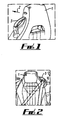
Figure 1 : is a partial rear quarter view of a vehicle seat according to the invention; -
Figure 2 : is a partial front view of the seat ofFigure 1 ; -
Figure 3 : is a cross-section through the squab release handle assembly of the seat ofFigure 1 in a closed position; -
Figure 4 : is a view corresponding toFigure 3 but with the handle in an open position; -
Figure 5 : is a cross-sectional view taken along the line A-A ofFigure 3 ; and -
Figure 6 : is an exploded view of the squab release handle assembly. - Referring to the drawings an automotive vehicle seat comprises a squab 1 (or seat back). The squab 1 is arranged so that it can be tilted forwards in a direction indicated by arrow 2 in
Figure 1 with respect to a cushion (not shown) into a so-called dumped position to allow access to the rear seats of a two door vehicle. This is common for front seats for two door vehicles. As is also common, the squab 1 is normally retained relative to the cushion by a latch which is released by a squab release handle when it is desired to move the squab to the dumped position. - A squab release handle assembly comprising a
squab release handle 3 is mounted towards the top of the outside of the seat squab 1. The handle comprises a generally U-shaped member. At one end the member is pivotally mounted to acast base piece 5 mounted to the squab 1. The opposite end of thehandle 3 forms anarcuate guide member 3a which is received into a Nyton (RTM) or other suitablematerial guide piece 6 received into thebase piece 5. Thehandle 3 may be pivoted between a normal position shown inFigure 3 , against the action of a return spring 7, to an open position shown inFigure 4 . When thehandle 3 is in the open position the seat squab 1 is unlocked with respect to the seat cushion and may be moved between normal and dumped positions. As thehandle 3 is engaged with thebase casting 5 at each of its opposite ends to provide a secure mounting to the squab, it may be used to move the squab between normal and dumped positions with one hand. Thehandle 3 further comprises aguard 3b which, together with part of the remainder of the handle, forms a loop. - The handle assembly also comprises
front 8 and rear 9 moulded covers. These attach to and conceal thebase casting 5 and may be trimmed to match or compliment the seat squab. Therear cover 9 is arranged to define a slot between the cover and thebase casting 5, through which seat belt webbing 10 pays out to form a shoulder strap of an integrated seat belt. - The seat belt webbing extends from a conventional inertia-type reel mounted inside the seat squab 1 to a lower anchorage point on the rear of the seat cushion. When the seat is not occupied the webbing lies generally as shown in
Figure 2 . When the seat is occupied the seat belt is drawn across the occupant and a buckle on the belt attached to an anchorage on the opposite side of the seat cushion. The webbing will then extend generally as shown bybroken lines 10a inFigure 2 . In normal use therefore the seat belt webbing extends over thebase casting 5, which forms an effective upper anchorage point for the seat belt which is therefore clear of theseat release handle 3. - Further, on operation of the handle a user's hand is effectively isolated from the webbing by the
guard 3a. - A seat according to the present invention combines the advantages of an integrated seat belt with those of a high mounted seat release handle. Although the handle and seat belt occupy a similar position of the seat squab under normal operation they do not interfere with each other.
- The above embodiment is described by way of example only. Many variations are possible without departing from the invention, according to claims 1 to 7.
Claims (7)
- A vehicle seat comprising a squab (1), a seat release handle (3) mounted on the squab and an aperture in the squab through which a seat belt (10) may pay out wherein the seat release handle (3) extends over the intended path of a seat belt (10) payed out from the aperture, characterised in that one end of the seat release handle (3) is pivotally mounted on the seat squab (1) to one side of the intended path of the seat belt and the opposite end of the seat release handle (3) comprises an arcuate member (3a) which is slidably received into a guide means (6) disposed on the seat squab (1) on the opposite side of the intended path of the seat belt (10).
- A vehicle seat as claimed in claim 1, the seat further comprising a seat belt (10) which extends out of the aperture and under the seat release handle (3).
- A vehicle seat as claimed in any preceding claim wherein the seat release handle (3) is operable between a normal position and an open position in which the seat may be moved to allow access behind the seat.
- A vehicle seat as claimed in claim 3 wherein movement of the seat release handle (3) from the normal to open position causes the handle to move away from the intended path of the seat belt (10).
- A vehicle seat as claimed in any preceding claim wherein the seat release handle (3) includes a guard (3b) arranged to lie between an operator of the handle's hand and the intended path of the seat belt.
- A vehicle seat as claimed in any preceding claim wherein the seat release handle is a loop handle.
- A vehicle seat as claimed in claim 2 and any of claims 3 to 6 when dependent, directly or indirectly, on claim 2 wherein the seat belt runs directly beneath the handle.
Applications Claiming Priority (1)
| Application Number | Priority Date | Filing Date | Title |
|---|---|---|---|
| GBGB0817081.3A GB0817081D0 (en) | 2008-09-18 | 2008-09-18 | Vehicle seat |
Publications (2)
| Publication Number | Publication Date |
|---|---|
| EP2165876A1 EP2165876A1 (en) | 2010-03-24 |
| EP2165876B1 true EP2165876B1 (en) | 2012-04-18 |
Family
ID=39951787
Family Applications (1)
| Application Number | Title | Priority Date | Filing Date |
|---|---|---|---|
| EP09275084A Active EP2165876B1 (en) | 2008-09-18 | 2009-09-18 | Vehicle seat |
Country Status (3)
| Country | Link |
|---|---|
| EP (1) | EP2165876B1 (en) |
| AT (1) | ATE553950T1 (en) |
| GB (1) | GB0817081D0 (en) |
Family Cites Families (6)
| Publication number | Priority date | Publication date | Assignee | Title |
|---|---|---|---|---|
| DE3530495A1 (en) * | 1985-08-27 | 1987-03-05 | Porsche Ag | SAFETY BELT, ESPECIALLY 3-POINT SAFETY BELT FOR VEHICLES, AIRPLANES OR THE LIKE |
| DE10341405B4 (en) | 2003-09-05 | 2010-02-25 | Audi Ag | Device for unlocking a folding backrest of a motor vehicle seat |
| DE102005027074A1 (en) | 2005-06-11 | 2006-12-14 | Recaro Gmbh & Co.Kg | Seat e.g. sport seat, for two-door motor vehicle, has backrest that is swivellable and lockable relative to seat part and comprising belt lead-through for safety belt and grip integrated in belt lead-through |
| FR2893288B1 (en) * | 2005-11-17 | 2007-12-14 | Peugeot Citroen Automobiles Sa | DEVICE FOR MAINTAINING THE USE OF A SAFETY BELT BELT OF A MOTOR VEHICLE SEAT |
| FR2916392B1 (en) * | 2007-05-24 | 2009-07-31 | Peugeot Citroen Automobiles Sa | INTEGRATED SAFETY BELT GUARD SEAT UNLOCKING ACTUATOR, AND CORRESPONDING UNLOCKING DEVICE AND SEAT |
| FR2920361B1 (en) * | 2007-08-29 | 2009-11-06 | Peugeot Citroen Automobiles Sa | SEAT UNLOCKING ACTUATOR WITH GUIDE HOUSING AND SEAT BELT EXTRACTION, AND CORRESPONDING UNLOCKING DEVICE AND SEAT. |
-
2008
- 2008-09-18 GB GBGB0817081.3A patent/GB0817081D0/en not_active Ceased
-
2009
- 2009-09-18 AT AT09275084T patent/ATE553950T1/en active
- 2009-09-18 EP EP09275084A patent/EP2165876B1/en active Active
Also Published As
| Publication number | Publication date |
|---|---|
| ATE553950T1 (en) | 2012-05-15 |
| GB0817081D0 (en) | 2008-10-29 |
| EP2165876A1 (en) | 2010-03-24 |
Similar Documents
| Publication | Publication Date | Title |
|---|---|---|
| EP1942029B1 (en) | Seat | |
| US6135529A (en) | Multi-position sliding center console | |
| US9956894B2 (en) | Apparatus for opening and closing sliding armrest console | |
| US6345856B1 (en) | Removable seat for automobile | |
| US7878567B2 (en) | Center console for a motor vehicle | |
| EP2221213B1 (en) | Integrated seat fold-down lever/belt exit | |
| JP5573363B2 (en) | Center console device for vehicle | |
| JP6262575B2 (en) | Vehicle seat | |
| US5673972A (en) | Vehicle seat assembly | |
| US11541792B2 (en) | Armrest assembly mounted on console of vehicle | |
| US3572818A (en) | Vehicle seat construction and arrangement | |
| JP2011246004A (en) | Center console device for vehicle | |
| US6964440B2 (en) | Outside vehicle door handle | |
| CN105263747A (en) | Vehicular seat | |
| US7530638B2 (en) | Dual action seat release mechanism | |
| EP2165876A1 (en) | Vehicle seat | |
| US20130292990A1 (en) | Light weight two-point aviation seatbelt | |
| JP2007285025A (en) | Locking device | |
| KR100968193B1 (en) | Cabin console of vehicle | |
| JP2003089329A (en) | On-vehicle roof box | |
| JP2003341431A (en) | Luggage floor device for automobile | |
| KR20080076468A (en) | Sheets for Heavy Construction Equipment | |
| JP6012158B2 (en) | Rotating body device and storage device | |
| US3068044A (en) | Safety arrangement, particularly for motor vehicles | |
| CN111688550B (en) | Vehicle seat |
Legal Events
| Date | Code | Title | Description |
|---|---|---|---|
| PUAI | Public reference made under article 153(3) epc to a published international application that has entered the european phase |
Free format text: ORIGINAL CODE: 0009012 |
|
| AK | Designated contracting states |
Kind code of ref document: A1 Designated state(s): AT BE BG CH CY CZ DE DK EE ES FI FR GB GR HR HU IE IS IT LI LT LU LV MC MK MT NL NO PL PT RO SE SI SK SM TR |
|
| AX | Request for extension of the european patent |
Extension state: AL BA RS |
|
| 17P | Request for examination filed |
Effective date: 20100920 |
|
| 17Q | First examination report despatched |
Effective date: 20110308 |
|
| GRAP | Despatch of communication of intention to grant a patent |
Free format text: ORIGINAL CODE: EPIDOSNIGR1 |
|
| GRAS | Grant fee paid |
Free format text: ORIGINAL CODE: EPIDOSNIGR3 |
|
| GRAA | (expected) grant |
Free format text: ORIGINAL CODE: 0009210 |
|
| AK | Designated contracting states |
Kind code of ref document: B1 Designated state(s): AT BE BG CH CY CZ DE DK EE ES FI FR GB GR HR HU IE IS IT LI LT LU LV MC MK MT NL NO PL PT RO SE SI SK SM TR |
|
| REG | Reference to a national code |
Ref country code: GB Ref legal event code: FG4D |
|
| REG | Reference to a national code |
Ref country code: CH Ref legal event code: EP |
|
| REG | Reference to a national code |
Ref country code: IE Ref legal event code: FG4D |
|
| REG | Reference to a national code |
Ref country code: AT Ref legal event code: REF Ref document number: 553950 Country of ref document: AT Kind code of ref document: T Effective date: 20120515 |
|
| REG | Reference to a national code |
Ref country code: DE Ref legal event code: R096 Ref document number: 602009006432 Country of ref document: DE Effective date: 20120614 |
|
| REG | Reference to a national code |
Ref country code: NL Ref legal event code: VDEP Effective date: 20120418 |
|
| REG | Reference to a national code |
Ref country code: AT Ref legal event code: MK05 Ref document number: 553950 Country of ref document: AT Kind code of ref document: T Effective date: 20120418 |
|
| LTIE | Lt: invalidation of european patent or patent extension |
Effective date: 20120418 |
|
| PG25 | Lapsed in a contracting state [announced via postgrant information from national office to epo] |
Ref country code: IS Free format text: LAPSE BECAUSE OF FAILURE TO SUBMIT A TRANSLATION OF THE DESCRIPTION OR TO PAY THE FEE WITHIN THE PRESCRIBED TIME-LIMIT Effective date: 20120818 Ref country code: PL Free format text: LAPSE BECAUSE OF FAILURE TO SUBMIT A TRANSLATION OF THE DESCRIPTION OR TO PAY THE FEE WITHIN THE PRESCRIBED TIME-LIMIT Effective date: 20120418 Ref country code: FI Free format text: LAPSE BECAUSE OF FAILURE TO SUBMIT A TRANSLATION OF THE DESCRIPTION OR TO PAY THE FEE WITHIN THE PRESCRIBED TIME-LIMIT Effective date: 20120418 Ref country code: CY Free format text: LAPSE BECAUSE OF FAILURE TO SUBMIT A TRANSLATION OF THE DESCRIPTION OR TO PAY THE FEE WITHIN THE PRESCRIBED TIME-LIMIT Effective date: 20120418 Ref country code: LT Free format text: LAPSE BECAUSE OF FAILURE TO SUBMIT A TRANSLATION OF THE DESCRIPTION OR TO PAY THE FEE WITHIN THE PRESCRIBED TIME-LIMIT Effective date: 20120418 Ref country code: SE Free format text: LAPSE BECAUSE OF FAILURE TO SUBMIT A TRANSLATION OF THE DESCRIPTION OR TO PAY THE FEE WITHIN THE PRESCRIBED TIME-LIMIT Effective date: 20120418 Ref country code: NO Free format text: LAPSE BECAUSE OF FAILURE TO SUBMIT A TRANSLATION OF THE DESCRIPTION OR TO PAY THE FEE WITHIN THE PRESCRIBED TIME-LIMIT Effective date: 20120718 |
|
| PG25 | Lapsed in a contracting state [announced via postgrant information from national office to epo] |
Ref country code: LV Free format text: LAPSE BECAUSE OF FAILURE TO SUBMIT A TRANSLATION OF THE DESCRIPTION OR TO PAY THE FEE WITHIN THE PRESCRIBED TIME-LIMIT Effective date: 20120418 Ref country code: PT Free format text: LAPSE BECAUSE OF FAILURE TO SUBMIT A TRANSLATION OF THE DESCRIPTION OR TO PAY THE FEE WITHIN THE PRESCRIBED TIME-LIMIT Effective date: 20120820 Ref country code: SI Free format text: LAPSE BECAUSE OF FAILURE TO SUBMIT A TRANSLATION OF THE DESCRIPTION OR TO PAY THE FEE WITHIN THE PRESCRIBED TIME-LIMIT Effective date: 20120418 Ref country code: GR Free format text: LAPSE BECAUSE OF FAILURE TO SUBMIT A TRANSLATION OF THE DESCRIPTION OR TO PAY THE FEE WITHIN THE PRESCRIBED TIME-LIMIT Effective date: 20120719 Ref country code: HR Free format text: LAPSE BECAUSE OF FAILURE TO SUBMIT A TRANSLATION OF THE DESCRIPTION OR TO PAY THE FEE WITHIN THE PRESCRIBED TIME-LIMIT Effective date: 20120418 |
|
| PG25 | Lapsed in a contracting state [announced via postgrant information from national office to epo] |
Ref country code: BE Free format text: LAPSE BECAUSE OF FAILURE TO SUBMIT A TRANSLATION OF THE DESCRIPTION OR TO PAY THE FEE WITHIN THE PRESCRIBED TIME-LIMIT Effective date: 20120418 |
|
| PG25 | Lapsed in a contracting state [announced via postgrant information from national office to epo] |
Ref country code: CZ Free format text: LAPSE BECAUSE OF FAILURE TO SUBMIT A TRANSLATION OF THE DESCRIPTION OR TO PAY THE FEE WITHIN THE PRESCRIBED TIME-LIMIT Effective date: 20120418 Ref country code: NL Free format text: LAPSE BECAUSE OF FAILURE TO SUBMIT A TRANSLATION OF THE DESCRIPTION OR TO PAY THE FEE WITHIN THE PRESCRIBED TIME-LIMIT Effective date: 20120418 Ref country code: AT Free format text: LAPSE BECAUSE OF FAILURE TO SUBMIT A TRANSLATION OF THE DESCRIPTION OR TO PAY THE FEE WITHIN THE PRESCRIBED TIME-LIMIT Effective date: 20120418 Ref country code: SK Free format text: LAPSE BECAUSE OF FAILURE TO SUBMIT A TRANSLATION OF THE DESCRIPTION OR TO PAY THE FEE WITHIN THE PRESCRIBED TIME-LIMIT Effective date: 20120418 Ref country code: RO Free format text: LAPSE BECAUSE OF FAILURE TO SUBMIT A TRANSLATION OF THE DESCRIPTION OR TO PAY THE FEE WITHIN THE PRESCRIBED TIME-LIMIT Effective date: 20120418 Ref country code: DK Free format text: LAPSE BECAUSE OF FAILURE TO SUBMIT A TRANSLATION OF THE DESCRIPTION OR TO PAY THE FEE WITHIN THE PRESCRIBED TIME-LIMIT Effective date: 20120418 Ref country code: EE Free format text: LAPSE BECAUSE OF FAILURE TO SUBMIT A TRANSLATION OF THE DESCRIPTION OR TO PAY THE FEE WITHIN THE PRESCRIBED TIME-LIMIT Effective date: 20120418 |
|
| PLBE | No opposition filed within time limit |
Free format text: ORIGINAL CODE: 0009261 |
|
| STAA | Information on the status of an ep patent application or granted ep patent |
Free format text: STATUS: NO OPPOSITION FILED WITHIN TIME LIMIT |
|
| PG25 | Lapsed in a contracting state [announced via postgrant information from national office to epo] |
Ref country code: IT Free format text: LAPSE BECAUSE OF FAILURE TO SUBMIT A TRANSLATION OF THE DESCRIPTION OR TO PAY THE FEE WITHIN THE PRESCRIBED TIME-LIMIT Effective date: 20120418 |
|
| 26N | No opposition filed |
Effective date: 20130121 |
|
| PG25 | Lapsed in a contracting state [announced via postgrant information from national office to epo] |
Ref country code: ES Free format text: LAPSE BECAUSE OF FAILURE TO SUBMIT A TRANSLATION OF THE DESCRIPTION OR TO PAY THE FEE WITHIN THE PRESCRIBED TIME-LIMIT Effective date: 20120729 Ref country code: MC Free format text: LAPSE BECAUSE OF NON-PAYMENT OF DUE FEES Effective date: 20120930 |
|
| REG | Reference to a national code |
Ref country code: DE Ref legal event code: R097 Ref document number: 602009006432 Country of ref document: DE Effective date: 20130121 |
|
| REG | Reference to a national code |
Ref country code: IE Ref legal event code: MM4A |
|
| PG25 | Lapsed in a contracting state [announced via postgrant information from national office to epo] |
Ref country code: IE Free format text: LAPSE BECAUSE OF NON-PAYMENT OF DUE FEES Effective date: 20120918 Ref country code: BG Free format text: LAPSE BECAUSE OF FAILURE TO SUBMIT A TRANSLATION OF THE DESCRIPTION OR TO PAY THE FEE WITHIN THE PRESCRIBED TIME-LIMIT Effective date: 20120718 |
|
| PG25 | Lapsed in a contracting state [announced via postgrant information from national office to epo] |
Ref country code: MT Free format text: LAPSE BECAUSE OF FAILURE TO SUBMIT A TRANSLATION OF THE DESCRIPTION OR TO PAY THE FEE WITHIN THE PRESCRIBED TIME-LIMIT Effective date: 20120418 |
|
| PG25 | Lapsed in a contracting state [announced via postgrant information from national office to epo] |
Ref country code: TR Free format text: LAPSE BECAUSE OF FAILURE TO SUBMIT A TRANSLATION OF THE DESCRIPTION OR TO PAY THE FEE WITHIN THE PRESCRIBED TIME-LIMIT Effective date: 20120418 |
|
| REG | Reference to a national code |
Ref country code: CH Ref legal event code: PL |
|
| PG25 | Lapsed in a contracting state [announced via postgrant information from national office to epo] |
Ref country code: LU Free format text: LAPSE BECAUSE OF NON-PAYMENT OF DUE FEES Effective date: 20120918 Ref country code: SM Free format text: LAPSE BECAUSE OF FAILURE TO SUBMIT A TRANSLATION OF THE DESCRIPTION OR TO PAY THE FEE WITHIN THE PRESCRIBED TIME-LIMIT Effective date: 20120418 |
|
| PG25 | Lapsed in a contracting state [announced via postgrant information from national office to epo] |
Ref country code: HU Free format text: LAPSE BECAUSE OF FAILURE TO SUBMIT A TRANSLATION OF THE DESCRIPTION OR TO PAY THE FEE WITHIN THE PRESCRIBED TIME-LIMIT Effective date: 20090918 Ref country code: LI Free format text: LAPSE BECAUSE OF NON-PAYMENT OF DUE FEES Effective date: 20130930 Ref country code: CH Free format text: LAPSE BECAUSE OF NON-PAYMENT OF DUE FEES Effective date: 20130930 |
|
| PG25 | Lapsed in a contracting state [announced via postgrant information from national office to epo] |
Ref country code: MK Free format text: LAPSE BECAUSE OF FAILURE TO SUBMIT A TRANSLATION OF THE DESCRIPTION OR TO PAY THE FEE WITHIN THE PRESCRIBED TIME-LIMIT Effective date: 20120418 |
|
| REG | Reference to a national code |
Ref country code: FR Ref legal event code: PLFP Year of fee payment: 8 |
|
| REG | Reference to a national code |
Ref country code: FR Ref legal event code: PLFP Year of fee payment: 9 |
|
| REG | Reference to a national code |
Ref country code: FR Ref legal event code: PLFP Year of fee payment: 10 |
|
| PGFP | Annual fee paid to national office [announced via postgrant information from national office to epo] |
Ref country code: FR Payment date: 20190909 Year of fee payment: 11 |
|
| PG25 | Lapsed in a contracting state [announced via postgrant information from national office to epo] |
Ref country code: FR Free format text: LAPSE BECAUSE OF NON-PAYMENT OF DUE FEES Effective date: 20200930 |
|
| PGFP | Annual fee paid to national office [announced via postgrant information from national office to epo] |
Ref country code: DE Payment date: 20220922 Year of fee payment: 14 |
|
| P01 | Opt-out of the competence of the unified patent court (upc) registered |
Effective date: 20230420 |
|
| REG | Reference to a national code |
Ref country code: DE Ref legal event code: R119 Ref document number: 602009006432 Country of ref document: DE |
|
| PG25 | Lapsed in a contracting state [announced via postgrant information from national office to epo] |
Ref country code: DE Free format text: LAPSE BECAUSE OF NON-PAYMENT OF DUE FEES Effective date: 20240403 |
|
| PGFP | Annual fee paid to national office [announced via postgrant information from national office to epo] |
Ref country code: GB Payment date: 20250903 Year of fee payment: 17 |