EP2165809A1 - Shaving razors - Google Patents
Shaving razors Download PDFInfo
- Publication number
- EP2165809A1 EP2165809A1 EP20090179263 EP09179263A EP2165809A1 EP 2165809 A1 EP2165809 A1 EP 2165809A1 EP 20090179263 EP20090179263 EP 20090179263 EP 09179263 A EP09179263 A EP 09179263A EP 2165809 A1 EP2165809 A1 EP 2165809A1
- Authority
- EP
- European Patent Office
- Prior art keywords
- blade
- aperture
- apertures
- cartridge
- array
- Prior art date
- Legal status (The legal status is an assumption and is not a legal conclusion. Google has not performed a legal analysis and makes no representation as to the accuracy of the status listed.)
- Withdrawn
Links
- 230000033001 locomotion Effects 0.000 claims description 15
- 210000004209 hair Anatomy 0.000 claims description 10
- 239000011888 foil Substances 0.000 claims description 6
- 230000002093 peripheral effect Effects 0.000 claims description 2
- 238000005201 scrubbing Methods 0.000 description 6
- 238000000034 method Methods 0.000 description 3
- 238000010191 image analysis Methods 0.000 description 1
Images





Classifications
-
- B—PERFORMING OPERATIONS; TRANSPORTING
- B26—HAND CUTTING TOOLS; CUTTING; SEVERING
- B26B—HAND-HELD CUTTING TOOLS NOT OTHERWISE PROVIDED FOR
- B26B21/00—Razors of the open or knife type; Safety razors or other shaving implements of the planing type; Hair-trimming devices involving a razor-blade; Equipment therefor
- B26B21/40—Details or accessories
- B26B21/4081—Shaving methods; Usage or wear indication; Testing methods
-
- B—PERFORMING OPERATIONS; TRANSPORTING
- B26—HAND CUTTING TOOLS; CUTTING; SEVERING
- B26B—HAND-HELD CUTTING TOOLS NOT OTHERWISE PROVIDED FOR
- B26B21/00—Razors of the open or knife type; Safety razors or other shaving implements of the planing type; Hair-trimming devices involving a razor-blade; Equipment therefor
- B26B21/08—Razors of the open or knife type; Safety razors or other shaving implements of the planing type; Hair-trimming devices involving a razor-blade; Equipment therefor involving changeable blades
- B26B21/14—Safety razors with one or more blades arranged transversely to the handle
- B26B21/20—Safety razors with one or more blades arranged transversely to the handle involving blades with more than two cutting edges; involving disc blades
-
- B—PERFORMING OPERATIONS; TRANSPORTING
- B26—HAND CUTTING TOOLS; CUTTING; SEVERING
- B26B—HAND-HELD CUTTING TOOLS NOT OTHERWISE PROVIDED FOR
- B26B21/00—Razors of the open or knife type; Safety razors or other shaving implements of the planing type; Hair-trimming devices involving a razor-blade; Equipment therefor
- B26B21/08—Razors of the open or knife type; Safety razors or other shaving implements of the planing type; Hair-trimming devices involving a razor-blade; Equipment therefor involving changeable blades
- B26B21/14—Safety razors with one or more blades arranged transversely to the handle
- B26B21/38—Safety razors with one or more blades arranged transversely to the handle with provision for reciprocating the blade by means other than rollers
-
- Y—GENERAL TAGGING OF NEW TECHNOLOGICAL DEVELOPMENTS; GENERAL TAGGING OF CROSS-SECTIONAL TECHNOLOGIES SPANNING OVER SEVERAL SECTIONS OF THE IPC; TECHNICAL SUBJECTS COVERED BY FORMER USPC CROSS-REFERENCE ART COLLECTIONS [XRACs] AND DIGESTS
- Y10—TECHNICAL SUBJECTS COVERED BY FORMER USPC
- Y10T—TECHNICAL SUBJECTS COVERED BY FORMER US CLASSIFICATION
- Y10T83/00—Cutting
- Y10T83/04—Processes
Definitions
- the shaving edge rather than being defined by the linear edge of an elongated blade, is defined by an aperture in a broad surface of a blade.
- a cutting edge is defined an aperture that has a sharpened edge.
- such razor blades will include an array of these apertures, e.g., apertures 12 shown in Fig. 1 .
- Patents describing such shaving systems include, for example, U.S. Patent Nos. 4,984,365 , 5,088,195 , 5,153,992 and 5,604,983 , the disclosures of which are incorporated herein by reference.
Landscapes
- Life Sciences & Earth Sciences (AREA)
- Forests & Forestry (AREA)
- Engineering & Computer Science (AREA)
- Mechanical Engineering (AREA)
- Dry Shavers And Clippers (AREA)
- Turbine Rotor Nozzle Sealing (AREA)
- Cosmetics (AREA)
Abstract
Description
- This invention relates to razors, and more particularly to razors for wet shaving.
- In some razors, the shaving edge, rather than being defined by the linear edge of an elongated blade, is defined by an aperture in a broad surface of a blade. For example, as described in
U.S. Patent No. 5,088,195 , the disclosure of which is incorporated herein by reference, a cutting edge is defined an aperture that has a sharpened edge. Generally, such razor blades will include an array of these apertures, e.g.,apertures 12 shown inFig. 1 . Patents describing such shaving systems include, for example,U.S. Patent Nos. 4,984,365 ,5,088,195 ,5,153,992 and5,604,983 , the disclosures of which are incorporated herein by reference. - The inventor has found that, when such razors are used, hairs can sometimes be missed due to small gaps between the effective shaving zones of the apertures. By "effective shaving zone," we mean the portion of the sharpened edge of each aperture that is positioned to cut hair when the blade is disposed in a razor and used in a normal manner (i.e., the razor is moved across the skin in the direction intended by the manufacturer). These gaps are illustrated diagrammatically in
FIGS. 2 and 2A . As shown inFIG. 2 , when the blade is moved across the skin in the direction indicated by arrow A, eachaperture 12 of theblade 10 has aneffective shaving zone 14 that will cut hair when the blade is drawn over the skin. The cutting effectiveness within eachzone 14 is distributed over a bell curve, as indicated bycurves 16 inFIG. 2 . These curves do not quite overlap, resulting ingaps 18, shown in detail inFIG. 2A . Eachgap 18 is approximately 150-250 microns in width. The width of a human beard hair is generally approximately 80 to 150 microns, and thus these tiny gaps can result in missed hairs. The effective shaving zone may be estimated, for example, by image analysis of high speed photography. - In general, the invention features razors in which these gaps are minimized or eliminated, generally resulting in a close, clean shave with very few or no missed hairs.
- In one aspect, the invention features a razor blade for use in a shaving system, the blade including a metallic foil sheet having a substantially planar surface with a plurality of apertures formed therein. The perimeter of each aperture forms a cutting edge, each cutting edge defining an effective cutting zone that will be positioned to cut hair when the razor blade is used in the shaving system. The blade further includes a peripheral surface extending outwardly from the periphery of said blade planar surface for mounting said blade into a shaving system. Importantly, the apertures are positioned relative to each other so that there is no distance, or a distance of less than 80 microns, between the effective cutting zone of each aperture and the effective cutting zone of each other aperture that is in an adjacent row and adjacent column. Due to this relative positioning, missed hairs are minimized or eliminated entirely. In some embodiments, there is no distance between the effective cutting zones or the effective cutting zones overlap.
- In another aspect, the invention features a shaving system including: (a) a cartridge carrying a blade, the blade comprising a metallic foil sheet having a substantially planar surface with a plurality of apertures formed therein, the perimeter of each said aperture forming a cutting edge; and (b) a handle having a distal end on which the cartridge is mounted; wherein a vertical axis of the cartridge is disposed at an angle with respect to a long axis of the handle. In some embodiments, the angle is selected so that when the razor is used with a normal stroking motion there is no distance, or a distance of less than 80 microns, between the effective cutting zone of each aperture and the effective cutting zone of each other aperture that is in an adjacent row and adjacent column.
- The invention also features methods of optimizing the shaving performance of a razor that includes a blade comprising a metallic foil sheet having a substantially planar surface with a plurality of apertures formed therein, the perimeter of each said aperture forming a cutting edge. In some cases, the apertures are arranged in an array having rows and columns, and the method includes arranging the apertures so that there is no distance, or a distance of less than 80 microns, between the effective cutting zone of each aperture and the effective cutting zone of each other aperture that is in an adjacent row and adjacent column. For example, the array may be positioned so that, when the blade is mounted in a cartridge, the array will be disposed at an angle with respect to a vertical axis of the cartridge. Other methods include utilizing the razor with a scrubbing motion.
- The details of one or more embodiments of the invention are set forth in the accompanying drawings and the description below. Other features, objects, and advantages of the invention will be apparent from the description and drawings, and from the claims.
-
-
FIG. 1 is a diagrammatic front plan view of an upper portion of a razor according to the prior art. -
FIG. 2 is a diagrammatic view of the blade of the razor shown inFIG. 1 , with effective shaving zone data from the razor ofFIG. 1 and the shaving direction employed with this razor superimposed on the blade.FIG. 2A is a highly enlarged illustration of the effective shaving zone data. -
FIG. 3 is a diagrammatic view of a blade according to one embodiment of the invention, with effective shaving zone data and shaving direction superimposed on the blade.FIG. 3A is a highly enlarged illustration of the effective shaving zone data. -
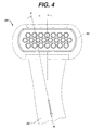
FIG. 4 is a diagrammatic front plan view of an upper portion of a razor according to another embodiment of the invention.FIG. 4A is a diagrammatic rear plan view of the razor ofFIG. 4 . -
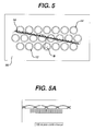
FIG. 5 is a diagrammatic view of the blade of the razor shown inFIG. 4 , with effective shaving zone data from the razor ofFIG. 4 and the resulting shaving direction of the blade when employed with this razor superimposed on the blade.FIG. 5A is a highly enlarged illustration of the effective shaving zone data. -
FIG. 6 is a diagrammatic front plan view of an upper portion of a razor according to another embodiment of the invention.FIG. 6A is a diagrammatic rear plan view of the razor ofFIG. 6 . -
FIGS. 7-7B are diagrammatic views showing the effective shaving zone data when the razor blade shown inFIG. 2 is used with various scrubbing motions. - A
blade 20, in which the gaps 18 (discussed above) are minimized or eliminated, is shown inFIG. 3 .Blade 20 can be used in a razor such as that shown inFIG. 1 , in whichcase blade 20 would generally be oriented in the cartridge in the same manner, and used in the same shaving direction, i.e., direction A indicated inFIG. 3 .Blade 20 includes an array of apertures in which the apertures are arranged differently than the apertures in the array onblade 10. As indicated by arrows SL and SR, the top and bottom rows of the array have been shifted right and left, respectively, so that the apertures in these two rows are offset (are not aligned) in the vertical direction. In other words, the center of each aperture is spaced horizontally from the center of each other aperture that is in an adjacent column and spaced two rows away. As shown inFIG. 3 , the centers of apertures in adjacent columns in the top and bottom rows are offset horizontally from each other by a distance D. Distance D will vary depending on the configuration of the blade (e.g., the diameter of the apertures and/or the spacing between the apertures within the same row). In some implementations, distance D is between about 0.05 mm and 2 mm, e.g., from about 0.1 to 1 mm. For a blade design in which the apertures have a diameter of 3 mm and a distance, center-to-center, of 4.2 mm, distance D may be between about 0.2 mm and 0.9 mm. By arranging the apertures in this manner,gaps 18 are eliminated and the effective shaving zones actually overlap, as shown diagrammatically inFIG. 3A . - Alternatively, the
gaps 18 can be minimized or eliminated by changing the orientation of the array of apertures as a whole relative to the long axis of the handle. Changing the orientation of the entire array will slightly change the radial orientation of the portion of each aperture that constitutes the effective shaving zone. This change of orientation will change the arrangement of the effective shaving zones in a manner similar to that discussed above with reference toFIGS. 3-3A . - Thus, referring to
FIGS. 4-5A , in one embodiment the orientation of the array relative to the long axis L of the handle is changed by changing the orientation of the cartridge relative to the handle.Razor 50 includes ahandle 52 and acartridge 54 mounted on the handle and carrying ablade 56.Blade 56 has substantially the same configuration as theblade 10 discussed above and shown inFIG. 2 . The razor differs, however, from the razor shown inFIG. 1 in that thecartridge 54 is mounted so that its vertical axis V is at an angle α relative to the long axis L of the handle. The angle α is selected to provide a desired resulting shaving direction of the blade (arrow B,FIG. 5 ) that will minimize or eliminate thegaps 18 discussed above, while allowing the user to use a normal shaving stroke (moving the handle in direction A,FIG. 4A ). While this angle will vary depending on the configuration of the blade (e.g., the diameter of the apertures and/or the spacing between the apertures within the same row), in some implementations angle α is between about 1 and 25 degrees, e.g., about 2 to 20 degrees. For a blade design in which the apertures have a diameter of 3 mm and a distance, center-to-center, of 4.2 mm, angle α may be from about 2.7 to 15 degrees. The resulting shaving direction B is rotated from the direction in which the user moves the handle (direction A) the same number of degrees. - The cartridge may be mounted at an angle, as discussed above, by providing an angled connector between the cartridge and the handle. Such connectors are well known in the art, and are described, for example, in
U.S. Patent No. 5,956,851 , the disclosure of which is incorporated herein by reference. Generally, the cartridge discussed above (often referred to as a blade unit) and the connector are sold together, as an integrated disposable unit (generally referred to as a whole as a "replaceable cartridge"). If desired, in addition to cartridges that are optimized for right-handed users, cartridges may be provided with the connector angled for left-handed users. If desired, the connector may include a pivotable portion, and may be position-settable between a right-handed position and a left-handed position. In this case, the connector is configured to lock in place at the desired "left-handed" angle and "right-handed" angle. - As shown in
FIG. 5 , when the blade is moved over the skin in the direction indicated by arrow B,gaps 18 are eliminated, and, as shown in detail inFIG. 5A , the effective shaving zones overlap. If it is not necessary that the effective shaving zones overlap, e.g., if it is acceptable that the "missed hair" phenomenon discussed above be reduced but not entirely eliminated, the angle α may be less. For example, suitable angles in this situation may be from about 0.1 to 10 degrees. - In another embodiment, shown in
FIGS. 6-6A , instead of orienting the cartridge at an angle, the array of apertures is oriented at an angle on the blade. Generally, the angle at which the array of apertures is oriented corresponds to the cartridge angles discussed above for the same design conditions. Thus, the array as a whole (and thus any single row in the array) is oriented at an angle with respect to the vertical axis V of the cartridge. This orientation will produce the same results discussed above and illustrated inFIG. 5A . - In a further embodiment, shown diagrammatically in
FIGS. 7-7B , thegaps 18 are eliminated by altering the shaving direction to include a circular scrubbing motion. It is generally preferred that the scrubbing motion be powered, e.g., using a battery powered razor having a head configured to move in an arcuate path, e.g., circular, oval, or other scrubbing motion. The parameters of the movement may be controlled, for example movement may be circular, having a predetermined diameter. The user is then free to control the direction of the shaving stroke as desired, using linear strokes or other shaving motion that the user is accustomed to. - As indicated in
FIGS. 7-7B , the diameter of the circles defined by a circular scrubbing motion will determine whethergaps 18 are reduced or eliminated entirely. For example, in the testing that is illustrated inFIGS. 7-7B , for a blade having apertures 3 mm in diameter, with their centers spaced 4.2 mm apart, a circular motion having a diameter of 6 mm completely eliminated gaps 18 (FIG. 7 ), while circular motions having diameters of 7 mm (FIG. 7A ) and5 mm (FIG. 7B ) reduced but did not eliminategaps 18. While the optimal diameter of the circular motion will vary depending on the blade design, for many embodiments it is preferred that the diameter of the circular motion be from about 4 mm to 10 mm, e.g., from about 5 mm to 7 mm. - Other embodiments are within the scope of the following claims.
- The dimensions and values disclosed herein are not to be understood as being strictly limited to the exact numerical values recited. Instead, unless otherwise specified, each such dimension is intended to mean both the recited value and a functionally equivalent range surrounding that value. For example, a dimension disclosed a "40 mm" is intended to mean "about 40 mm".
Claims (11)
- A razor blade (20) for employment in a shaving system, said blade comprising:a metallic foil sheet, said sheet having a substantially planar surface with a plurality of apertures (12) formed therein, the perimeter of each said aperture forming a cutting edge, each cutting edge defining an effective cutting zone (14) that will be positioned to cut hair when the razor blade is used in the shaving system,said blade (20) further comprising a peripheral surface extending outwardly from the periphery of said blade planar surface for mounting said blade into a shaving system,wherein the apertures (12) are positioned relative to each other so that there is a distance (18) of less than 80 microns, between the effective cutting zone (14) of each aperture (12) and the effective cutting zone (14) of each other aperture (12) that is in an adjacent row and adjacent column.
- The razor blade of claim 1 wherein there is a distance (18) of from about 0.1 to 1.0 mm between the center of each aperture (12) and the center of each other aperture that is in an adjacent column and spaced two rows away.
- The razor blade of claim 1 or claim 2 wherein there is no distance (18) between the effective cutting zones.
- The razor blade of claim 3 wherein the effective cutting zones (14) overlap.
- The razor blade of any one of the proceeding claims wherein the apertures (12) are arranged in an array having rows and columns and said array is positioned so that, when the blade is mounted in a cartridge (54), the array will be disposed at an angle (α) with respect to a vertical axis (V) of the cartridge (54).
- The razor blade of claim 5 wherein the angle is from about 1 to 25 degrees.
- A shaving system comprising:a cartridge (54) carrying a blade (20), the blade comprising a metallic foil sheet having a substantially planar surface with a plurality of apertures (12) formed therein, the perimeter of each said aperture (12) forming a cutting edge; anda handle (52) having a distal end on which the cartridge (54) is mounted;wherein a vertical axis (V) of the cartridge is disposed at an angle (α) with respect to a long axis (L)of the handle (52).
- The shaving system of claim 7 wherein the angle (α) is from about 1 to 25 degrees.
- The shaving system of claim 7 or claim 8 wherein the angle (α) is selected so that when the razor is used with a normal stroking motion there is no distance (18), or a distance (18) of less than 80 microns, between the effective cutting zone (14) of each aperture (12) and the effective cutting zone (14) of each other aperture (12) that is in an adjacent row and adjacent column.
- A shaving system comprising:a cartridge (54) carrying a blade (10; 20), the blade comprising a metallic foil sheet having a substantially planar surface with a plurality of apertures (12) formed therein, the perimeter of each said aperture (12) forming a cutting edge and the apertures (12) being arranged in an array having rows and columns, each column defined by an imaginary column line intersecting centers of apertures (12) that are spaced from one another by an intermediate row; anda handle (52) having a distal end on which the cartridge (54) is mounted, the handle adapted for being drawn along a shaving direction axis (A) through the handle; whereinsaid imaginary column line of the array is disposed at an angle (α) with respect to the saving direction (A).
- The shaving system of claim 10, wherein the imaginary column line of the array is substantially orthogonal to an axis of elongation of the cartridge (54).
Applications Claiming Priority (2)
| Application Number | Priority Date | Filing Date | Title |
|---|---|---|---|
| US11/145,341 US20060272460A1 (en) | 2005-06-02 | 2005-06-02 | Shaving razors |
| EP20060771682 EP1899118B1 (en) | 2005-06-02 | 2006-05-31 | Method of optimizing the shaving performance of a razor |
Related Parent Applications (1)
| Application Number | Title | Priority Date | Filing Date |
|---|---|---|---|
| EP06771682.9 Division | 2006-05-31 |
Publications (1)
| Publication Number | Publication Date |
|---|---|
| EP2165809A1 true EP2165809A1 (en) | 2010-03-24 |
Family
ID=37310290
Family Applications (2)
| Application Number | Title | Priority Date | Filing Date |
|---|---|---|---|
| EP20060771682 Active EP1899118B1 (en) | 2005-06-02 | 2006-05-31 | Method of optimizing the shaving performance of a razor |
| EP20090179263 Withdrawn EP2165809A1 (en) | 2005-06-02 | 2006-05-31 | Shaving razors |
Family Applications Before (1)
| Application Number | Title | Priority Date | Filing Date |
|---|---|---|---|
| EP20060771682 Active EP1899118B1 (en) | 2005-06-02 | 2006-05-31 | Method of optimizing the shaving performance of a razor |
Country Status (8)
| Country | Link |
|---|---|
| US (1) | US20060272460A1 (en) |
| EP (2) | EP1899118B1 (en) |
| JP (1) | JP4874331B2 (en) |
| CN (1) | CN100563951C (en) |
| AT (1) | ATE452008T1 (en) |
| DE (1) | DE602006011159D1 (en) |
| MX (1) | MX2007015251A (en) |
| WO (1) | WO2006130648A2 (en) |
Cited By (2)
| Publication number | Priority date | Publication date | Assignee | Title |
|---|---|---|---|---|
| WO2020128706A1 (en) | 2018-12-21 | 2020-06-25 | Brengor Innovation Ltd | Razor |
| GB2593407A (en) * | 2021-07-08 | 2021-09-22 | Brengor Innovation Ltd | Razor blade |
Families Citing this family (7)
| Publication number | Priority date | Publication date | Assignee | Title |
|---|---|---|---|---|
| JP6005495B2 (en) * | 2012-12-06 | 2016-10-12 | 株式会社泉精器製作所 | Manufacturing method of outer blade of rotary electric razor |
| EP3231564B1 (en) * | 2016-03-31 | 2020-07-01 | The Gillette Company LLC | Razor cartridge with fluid management system |
| CN109259634B (en) * | 2018-10-23 | 2021-06-15 | 宁波沃腾玛尔洁具有限公司 | A smart massage bathtub |
| EP4079471A1 (en) * | 2021-04-20 | 2022-10-26 | GFD Gesellschaft für Diamantprodukte mbH | Cutting element and hair removal device |
| EP4079472A1 (en) * | 2021-04-20 | 2022-10-26 | GFD Gesellschaft für Diamantprodukte mbH | Cutting element with asymmetric cutting segments |
| EP4079473A1 (en) * | 2021-04-20 | 2022-10-26 | GFD Gesellschaft für Diamantprodukte mbH | Cutting element and hair removal device |
| US20240227220A1 (en) * | 2023-01-09 | 2024-07-11 | The Gillette Company Llc | Hair removal device |
Citations (3)
| Publication number | Priority date | Publication date | Assignee | Title |
|---|---|---|---|---|
| US2439909A (en) * | 1945-12-12 | 1948-04-20 | George E Hale | Safety razor blade |
| EP0039567A1 (en) * | 1980-04-30 | 1981-11-11 | Wilkinson Sword Limited | Razors, razor blades and razor blade dispensers |
| US5031318A (en) * | 1990-03-22 | 1991-07-16 | The Gillette Company | Safety razor |
Family Cites Families (19)
| Publication number | Priority date | Publication date | Assignee | Title |
|---|---|---|---|---|
| US2614321A (en) * | 1950-12-23 | 1952-10-21 | Ackerman Charles | Safety razor |
| US2989804A (en) * | 1959-06-30 | 1961-06-27 | Edgar Bernhard | Self protected shaving device having multiple cutting edges |
| US3702026A (en) * | 1971-10-18 | 1972-11-07 | Unirazor Ltd | Razor |
| MA21155A1 (en) * | 1987-01-09 | 1988-10-01 | Gillette Co | MECHANICAL RAZORS. |
| US4807360A (en) * | 1987-09-02 | 1989-02-28 | The Gillette Company | Shaving device |
| US4875288A (en) * | 1987-09-02 | 1989-10-24 | The Gillette Company | Shaving device |
| GB2224044B (en) * | 1988-10-15 | 1993-06-23 | Matsushita Electric Works Ltd | Hand-held clipper for removing entangled fibres from the surface of fabrics |
| EP0436693B1 (en) * | 1989-07-24 | 1994-02-16 | The Gillette Company | Safety razors |
| US4977670A (en) * | 1989-12-18 | 1990-12-18 | American Safety Razor Company | Shaving implement |
| US4979298A (en) * | 1990-04-10 | 1990-12-25 | The Gillette Company | Shaving system |
| US4984365A (en) * | 1990-05-04 | 1991-01-15 | The Gillette Company | Safety razor |
| US5088195A (en) * | 1990-07-30 | 1992-02-18 | Lazarshik Daniel B | Shaving system |
| US5201253A (en) * | 1990-07-30 | 1993-04-13 | The Gillette Company | Shaving system |
| US5031317A (en) * | 1990-09-19 | 1991-07-16 | The Gillette Co. | Razor |
| USD373218S (en) * | 1994-04-14 | 1996-08-27 | The Gillette Company | Safety razor cartridge |
| US5604983A (en) * | 1994-04-14 | 1997-02-25 | The Gillette Company | Razor system |
| US5490329A (en) * | 1994-05-17 | 1996-02-13 | The Gillette Company | Shaving system |
| US5956851A (en) * | 1996-04-10 | 1999-09-28 | The Gillette Company | Shaving system including handle and replaceable cartridges |
| EP1597032A2 (en) * | 2003-02-25 | 2005-11-23 | Eveready Battery Company, Inc. | A method for manufacturing a razor blade |
-
2005
- 2005-06-02 US US11/145,341 patent/US20060272460A1/en not_active Abandoned
-
2006
- 2006-05-31 MX MX2007015251A patent/MX2007015251A/en active IP Right Grant
- 2006-05-31 EP EP20060771682 patent/EP1899118B1/en active Active
- 2006-05-31 AT AT06771682T patent/ATE452008T1/en not_active IP Right Cessation
- 2006-05-31 DE DE200660011159 patent/DE602006011159D1/en active Active
- 2006-05-31 WO PCT/US2006/021045 patent/WO2006130648A2/en not_active Ceased
- 2006-05-31 EP EP20090179263 patent/EP2165809A1/en not_active Withdrawn
- 2006-05-31 CN CNB200680019427XA patent/CN100563951C/en active Active
- 2006-05-31 JP JP2008513840A patent/JP4874331B2/en active Active
Patent Citations (3)
| Publication number | Priority date | Publication date | Assignee | Title |
|---|---|---|---|---|
| US2439909A (en) * | 1945-12-12 | 1948-04-20 | George E Hale | Safety razor blade |
| EP0039567A1 (en) * | 1980-04-30 | 1981-11-11 | Wilkinson Sword Limited | Razors, razor blades and razor blade dispensers |
| US5031318A (en) * | 1990-03-22 | 1991-07-16 | The Gillette Company | Safety razor |
Cited By (5)
| Publication number | Priority date | Publication date | Assignee | Title |
|---|---|---|---|---|
| WO2020128706A1 (en) | 2018-12-21 | 2020-06-25 | Brengor Innovation Ltd | Razor |
| US11524420B2 (en) | 2018-12-21 | 2022-12-13 | Brengor Innovation Ltd | Razor |
| GB2593407A (en) * | 2021-07-08 | 2021-09-22 | Brengor Innovation Ltd | Razor blade |
| GB2593407B (en) * | 2021-07-08 | 2022-04-27 | Brengor Innovation Ltd | Razor blade |
| WO2023281355A1 (en) | 2021-07-08 | 2023-01-12 | Brengor Innovation Ltd | Razor blade |
Also Published As
| Publication number | Publication date |
|---|---|
| JP2008541888A (en) | 2008-11-27 |
| US20060272460A1 (en) | 2006-12-07 |
| EP1899118B1 (en) | 2009-12-16 |
| CN101189104A (en) | 2008-05-28 |
| WO2006130648A2 (en) | 2006-12-07 |
| DE602006011159D1 (en) | 2010-01-28 |
| MX2007015251A (en) | 2008-02-22 |
| CN100563951C (en) | 2009-12-02 |
| WO2006130648A3 (en) | 2007-04-26 |
| ATE452008T1 (en) | 2010-01-15 |
| JP4874331B2 (en) | 2012-02-15 |
| EP1899118A2 (en) | 2008-03-19 |
Similar Documents
| Publication | Publication Date | Title |
|---|---|---|
| AU2023203465B2 (en) | Bidirectional shaving device | |
| EP1484144B1 (en) | Shaving razor and blade unit with improved guard | |
| EP1930136B1 (en) | Dry shaver | |
| EP2158067B1 (en) | A shaving apparatus, a cutting unit and a shaving head | |
| US8011102B2 (en) | Dry shaver | |
| US7730621B2 (en) | Shaving foil for a dry shaver | |
| EP2181815B1 (en) | Wet razor with four blades, and cartridge therefor | |
| EP2440376B1 (en) | Blade cartridge with finned guard | |
| EP1722945B1 (en) | Shaving razor with additional trimming blade | |
| US6035535A (en) | Flexible safety razor head with intrinsically fenced cantilevered cutting edges | |
| EP4257307B1 (en) | Razor cartridge | |
| EP1273400B1 (en) | Shaving implement having static and dynamic blades | |
| EP2165809A1 (en) | Shaving razors |
Legal Events
| Date | Code | Title | Description |
|---|---|---|---|
| PUAI | Public reference made under article 153(3) epc to a published international application that has entered the european phase |
Free format text: ORIGINAL CODE: 0009012 |
|
| AC | Divisional application: reference to earlier application |
Ref document number: 1899118 Country of ref document: EP Kind code of ref document: P |
|
| AK | Designated contracting states |
Kind code of ref document: A1 Designated state(s): AT BE BG CH CY CZ DE DK EE ES FI FR GB GR HU IE IS IT LI LT LU LV MC NL PL PT RO SE SI SK TR |
|
| 17P | Request for examination filed |
Effective date: 20100902 |
|
| 17Q | First examination report despatched |
Effective date: 20101028 |
|
| STAA | Information on the status of an ep patent application or granted ep patent |
Free format text: STATUS: THE APPLICATION IS DEEMED TO BE WITHDRAWN |
|
| 18D | Application deemed to be withdrawn |
Effective date: 20110510 |