EP2165647A1 - Apparatus for determining optical and spatial characteristics of an inclusion in a turbid medium using multiple-scattering optical tomography - Google Patents
Apparatus for determining optical and spatial characteristics of an inclusion in a turbid medium using multiple-scattering optical tomography Download PDFInfo
- Publication number
- EP2165647A1 EP2165647A1 EP08019605A EP08019605A EP2165647A1 EP 2165647 A1 EP2165647 A1 EP 2165647A1 EP 08019605 A EP08019605 A EP 08019605A EP 08019605 A EP08019605 A EP 08019605A EP 2165647 A1 EP2165647 A1 EP 2165647A1
- Authority
- EP
- European Patent Office
- Prior art keywords
- optical
- inclusion
- photon beams
- turbid medium
- light sources
- Prior art date
- Legal status (The legal status is an assumption and is not a legal conclusion. Google has not performed a legal analysis and makes no representation as to the accuracy of the status listed.)
- Ceased
Links
Images




Classifications
-
- A—HUMAN NECESSITIES
- A61—MEDICAL OR VETERINARY SCIENCE; HYGIENE
- A61B—DIAGNOSIS; SURGERY; IDENTIFICATION
- A61B5/00—Measuring for diagnostic purposes; Identification of persons
- A61B5/43—Detecting, measuring or recording for evaluating the reproductive systems
- A61B5/4306—Detecting, measuring or recording for evaluating the reproductive systems for evaluating the female reproductive systems, e.g. gynaecological evaluations
- A61B5/4312—Breast evaluation or disorder diagnosis
-
- A—HUMAN NECESSITIES
- A61—MEDICAL OR VETERINARY SCIENCE; HYGIENE
- A61B—DIAGNOSIS; SURGERY; IDENTIFICATION
- A61B5/00—Measuring for diagnostic purposes; Identification of persons
- A61B5/0059—Measuring for diagnostic purposes; Identification of persons using light, e.g. diagnosis by transillumination, diascopy, fluorescence
- A61B5/0073—Measuring for diagnostic purposes; Identification of persons using light, e.g. diagnosis by transillumination, diascopy, fluorescence by tomography, i.e. reconstruction of 3D images from 2D projections
-
- A—HUMAN NECESSITIES
- A61—MEDICAL OR VETERINARY SCIENCE; HYGIENE
- A61B—DIAGNOSIS; SURGERY; IDENTIFICATION
- A61B5/00—Measuring for diagnostic purposes; Identification of persons
- A61B5/0059—Measuring for diagnostic purposes; Identification of persons using light, e.g. diagnosis by transillumination, diascopy, fluorescence
- A61B5/0082—Measuring for diagnostic purposes; Identification of persons using light, e.g. diagnosis by transillumination, diascopy, fluorescence adapted for particular medical purposes
- A61B5/0091—Measuring for diagnostic purposes; Identification of persons using light, e.g. diagnosis by transillumination, diascopy, fluorescence adapted for particular medical purposes for mammography
-
- A—HUMAN NECESSITIES
- A61—MEDICAL OR VETERINARY SCIENCE; HYGIENE
- A61B—DIAGNOSIS; SURGERY; IDENTIFICATION
- A61B5/00—Measuring for diagnostic purposes; Identification of persons
- A61B5/48—Other medical applications
- A61B5/4887—Locating particular structures in or on the body
-
- G—PHYSICS
- G01—MEASURING; TESTING
- G01N—INVESTIGATING OR ANALYSING MATERIALS BY DETERMINING THEIR CHEMICAL OR PHYSICAL PROPERTIES
- G01N21/00—Investigating or analysing materials by the use of optical means, i.e. using sub-millimetre waves, infrared, visible or ultraviolet light
- G01N21/17—Systems in which incident light is modified in accordance with the properties of the material investigated
- G01N21/47—Scattering, i.e. diffuse reflection
- G01N21/4795—Scattering, i.e. diffuse reflection spatially resolved investigating of object in scattering medium
-
- A—HUMAN NECESSITIES
- A61—MEDICAL OR VETERINARY SCIENCE; HYGIENE
- A61B—DIAGNOSIS; SURGERY; IDENTIFICATION
- A61B5/00—Measuring for diagnostic purposes; Identification of persons
- A61B5/72—Signal processing specially adapted for physiological signals or for diagnostic purposes
- A61B5/7203—Signal processing specially adapted for physiological signals or for diagnostic purposes for noise prevention, reduction or removal
Definitions
- the invention relates to an apparatus for determining optical and spatial characteristics of an inclusion in a turbid medium using multiple-scattering optical tomography, especially by using a continuous wave laser.
- Imaging through turbid media has become an important field of research, for its great potential in diverse fields of applications like meteorology, ecology, aviation, astrophysics, etc.
- Basic limitations are posed by the effect of multiple scattering of light as well as hardware schematics whereby minimizing the multiple scattering effects are difficult to realize.
- optical tomography techniques like the double-side optical tomography, are based mainly on a transmission approach for detection of radiation transmitted through the turbid medium, in other words based on a forward scattering method.
- This method is characterized by double-side schematics, problems with a determination of the optical characteristics of the turbid medium, large measurement times of ballistic and snake photons and an impossibility to distinguish between normal and abnormal tissues.
- a turbid medium is a strongly scattering material, for example a tissue.
- An inclusion is a volume of a different material being a turbid medium of different scattering characteristics enclosed in the strongly scattering material.
- Spatial characteristics are to be understood as a totality of information comprising a position of the inclusion relative to a reference point, as well as 3-dimensional coordinates describing a volume of the inclusion.
- Optical characteristics describe an interaction of light with the turbid medium and the inclusion, like an absorption coefficient ⁇ a, an integral scattering coefficient ⁇ s, a back scattering coefficient ⁇ , an extinction coefficient ⁇ being a sum of the absorption coefficient and the integral scattering coefficient, and a scattering angular dependence ⁇ ( ⁇ ) on the angle ⁇ between an incident and a scattering direction, which is assumed to be sharply forward oriented, meaning that it sharply drops to zero at an angle close to zero.
- forward scattering is used for photons which have undergone few scattering events and travel in the direction of the incident radiation under certain angles, less than ⁇ /2 to the incident radiation direction.
- back scattering refers to photons which have undergone multiple scattering events and travel in a direction opposite to the incident radiation within a given solid angle.
- an apparatus for determining optical and spatial characteristics of an inclusion in a turbid medium using multiple-scattering optical tomography comprising:
- the apparatus therefore allows to determine the optical and spatial characteristics of an inclusion by simply observing the backscattered photon beams.
- the evaluation of the light intensity distribution for the backscattered photon beams enables the principal opportunity to use the apparatus for creation of miniature instruments for future applications in medical practice since the instrument can be designed similar to an ultrasonic head.
- control unit is preferably further enabled:
- a further preferred embodiment of the present invention resides in the construction of the filter array.
- a preferred filter array may comprise a number of distributed tube-like filter channels, said distributed tube-like filter channels being oriented parallel to each other along the direction of the optical axis (z) in order to reject and/or to absorb all particular backscattered photon beams which lack the substantial parallel orientation to the optical axis (z).
- said filter channels may be formed as cylindrical apertures within a filter block, said cylindrical apertures being oriented parallel to the optical axis (z).
- each light source preferably emits its collimated laser incident radiation along the optical axis, each of the radiations originating from a different continuous wave laser.
- the filter array may additionally host the array of light sources, thereby comprising an even periodical distribution of the detector elements and light sources as seen in the cross-sectional area oriented perpendicular to the optical axis.
- Even distribution in the context does not mean an equal periodicity of both the detector elements and the light sources but that both the detector elements and light sources have a regular periodicity but notably not the same periodicity. Therefore, the number of detector elements may be at least twice as big as the number of light sources. I.e., the detector elements and the light elements are disposed in regular chessboard-like pattern whereby each light source comprises at least four exclusive detector elements juxtaposed, preferably eight exclusive detector elements.
- the light sources are preferably controlled by the control unit; said control unit allowing the light sources to emit one after the other and only one at a time. Accordingly, the control unit is preferably collecting the detected optical output power in response to each of the emitted multiple radiations.
- a specific backscattered photon beam 7, which is parallel to the optical axis z is optically linked after passing the contact surface 3 through an optical detection and measurement block 8 with a computer and algorithms block 9.
- the operation of the apparatus A in Fig.1 based on the method for optical tomography mentioned above is as follows.
- the input collimated optical radiation 4 begins to scatter immediately after entering the turbid medium 1 through the contact surface 3.
- the turbid medium 1 containing the inclusion 2 will be illuminated within a spread angle ⁇ .
- a part of this radiation 4, backscattered in parallel to the optical axis z contains, after passing the contact surface 3, the specific photon beam 7, which is then optically detected and measured by the optical detection and measurement block 8.
- the step ⁇ k is defined as the minimum distance between the adjacent non-overlapped specific photon beams along the x -axis.
- This set can be denoted by S j x k x ⁇ p x ⁇ p z k x , j x in the presence of an inclusion, and by S j x k x k x , j x in the absence of any inclusions.
- the operation of the apparatus in Fig.2 based on the method for optical tomography and the apparatus A in Fig.1 is as follows.
- one of the emitting lasers (say, j x ) of the set 5 1 ...5 J x is switched to an "ON" state, while all other lasers are kept in an “OFF” state.
- the optical detectors in the optical multi-detection and measurement system 10 are always in the "ON" condition. Each of these optical detectors will measure the optical powers from the corresponding specific backscattered photon beams 7 1 ??7 K x .
- the emitting laser is switched “OFF” and the next laser j x +1 will switch “ON", while all other lasers remain in “OFF” state.
- the optical detectors in the optical multi-detection and measurement system 10 remain in the "ON" state.
- the recorded set of output signals for this case will be S j x + 1 k x ⁇ p x ⁇ p z k x .
- the entire set of output signals S j x k x ⁇ p x ⁇ p z k x , j x in the presence of an inclusion, and S j x k x k x , j x in the absence of any inclusions, that is necessary to calculate (block 9) the coordinates of the inclusion 2 and the optical characteristics of the turbid medium 1 and the inclusion 2, will be created after successive switching in "ON" state the entire set of emitting lasers 5 1 ...5 J x .
- all the elements of the apparatus remain unmoved. Moreover, the full measurement time can be thus minimized.
- the two-dimensional optical multi-detector system 11 contains a two-dimensional set of optical detectors, each one linked to the corresponding specific backscattered photon beams of the set 7 1 ...7 K x ,7 1 ...7 K y .
- the operation of the two dimensional apparatus in Fig.3 is similar to that of the one dimensional apparatus in Fig.2 .
- one of the lasers in the laser matrix 5 1 ...5 J x ,5 1 ...5 J y is in "ON” state, while all other lasers are switched to "OFF” state.
- the next laser in the matrix will be switched to "ON” state, while all other lasers are switched to "OFF” state.
- the two dimensional matrix 7 1 ...7 K x ,7 1 ...7 K y of optical detectors remains always in "ON" state.
- Fig.4 represents one possible implementation of the key block K, providing forming of the specific backscattered photon beam 7, which is parallel to the optical axis z.
- the formation of the backscattered photon beam 7 is realized by spatial filtering of scattered radiation using a tiny cylindrical tube 12 of internal diameter d tube and length l tube and an optical fiber 13.
- the tiny tube 12 is disposed with one of its edges near the laser beam 4 with an axis, parallel to the laser beam.
- the optical fiber 13 is inserted with one of its edges into the opposite (rear) edge of the tube 12, while the other fiber edge is fed to the optical detector of the optical detection & measuring system 8.
- the length l tube of the tube 12 is assumed to be too long with respect to the internal diameter d tube , i.e. d tube ⁇ l tube .
- the basic function of tubes is to provide the very narrow field of view for the photon detection.
- the tube angle of view ⁇ tube could be approximately determined by the expression ⁇ tube ⁇ d tube / l tube (say, for d tube ⁇ 0.1 cm and l tube ⁇ 5 cm we obtain that the tube field of view will be of the order of ⁇ tube ⁇ 20 mrad).
- the lateral receiving spot diameter will be of the order of 1.5 mm and thus, the overlapping of adjacent specific backscattered photon beams 7 can be easily avoided.
- the angular filtering can be improved by deposition of some absorbing coating on the internal wall of the tube 12.
- the set of specific backscattered photon beams for the 2D implementation of the apparatus can be formed (according to Figures 2 and 3 ) by a set of parallel tiny tubes 12 1 ...12 K x ,12 1 ...12 K y with corresponding optical fibers 13 1 ...13 K x ,13 1 ...13 K y .
- the outputs of optical fibers 13 1 ...13 K x ,13 1 ...13 K y are fed to corresponding optical detectors, disposed within the multi-channel optical detection and measurements system 11.
- the distance between the adjacent tiny tubes 12 will be equal to the step of the matrix in Fig.3 . In this case the matrix in Fig.
- Fig.5 presents a possible 2D implementation of the block of lasers in the matrix in Fig.3 and in Fig.4 .
- the emitted radiation from the two-dimensional block of lasers 5 1 ...5 J x ,5 1 ...5 J y (as in Fig.3 ) is directed into the optical fibers 14 1 ...14 J x ,14 1 ...14 J y .
- Lenses 15 1 ...15 J x ,15 1 ...15 J y are disposed on the opposite fiber edges (in some other configuration the lenses 15 1 ...15 J x ,15 1 ...15 J y are implemented on the fiber edges).
- the use of lenses 15 provides an emission of collimated laser beams into the turbid medium 1.
- the optical bunch 16 contains the fibers 13 1 ...13 K x ,13 1 ...13 K y of the receiving part of the apparatus and the fibers 14 1 ...14 J x ,14 1 ...14 J y of the emitting part.
- the optical detectors within the multi-channel optical detection and measurement system 11 are correspondingly linked with the fibers 13 1 ...13 K x ,13 1 ...13 K y .
- the optical fibers 14 1 ...14 J x ,14 1 ...14 J y in the emitting part are correspondingly linked with the lasers 5 1 ...5 J x 5 1 ...5 J y .
- the configuration of the apparatus in Fig.5 provides electrical separation of the apparatus as a whole from the contact surface 3 that is connected mechanically with the patient, in particular which is the skin of the patient.
- FIG.6 One possible realization of the optical multi-detection unit of the optical multi-detection and measurement system 11 is shown in Fig.6 .
- the properly in space arranged set of edges of fibers 13 1 ...13 K x ,13 1 ...13 K y illuminates a surface 17 of a photosensitive matrix (say, CCD-matrix, intensifier photosensitive surface, etc.).
- the special arrangement of fibers 13 is chosen by the condition that the corresponding light spots 18 1 ...18 K x ,18 1 ...18 K y , created by each of the fibers 13 be non-overlapped. Under these conditions the set of optical detectors in the optical multi-detection measurement system 11 is replaced by a single photosensitive matrix.
- the energies in the set of light spots on the single photosensitive matrix are proportional to the corresponding output signals S j x , j y k x ⁇ k y ⁇ p x ⁇ p y ⁇ p z k x , k y , j x , j y or S j x , j y 0 k x ⁇ k y k x , k y , j x , j y , that are necessary to determine the coordinates of the inclusion 2 and the optical characteristics of the turbid medium 1 and the inclusion 2.
- CCD-optical receiver the set of above signals, one can essentially reduce the implementation of the apparatus.
- the optomechanical matrix (according to realizations in Fig.5 and Fig.6 ) is in contact with patients. It is well known that the patient breast tissue can be considered as a turbid medium.
- the optomechanical matrix 19 illuminates the patient breast tissue (containing, say, some cancer-type inclusions).
- the backscattered radiation formed in a set of parallel photon beams (see Fig.4 and Fig.5 ) is transformed (see Fig.6 ) in a set of arranged light spots of defined energies. Then, the set of spots is transformed further by a receiving electronics/amplification/recording block 20 into a set of signals.
- the recorded set of signals S j x , j y k x ⁇ k y ⁇ p x ⁇ p y ⁇ p z k x , k y , j x , j y or S j x , j y 0 k x ⁇ k y k x , k y , j x , j y is then processed by a processor block 22.
- the output results are imaged at least on a monitor together with the information about the inclusion coordinates and their optical characteristics. This information is further processed in order to determine the specificity of the inclusions.
- FIG.8 one possible implementation of the apparatus A as a whole is given in Fig.8 for illustration.
- the basic block of this apparatus demonstrates the principal opportunity to use both the method and the apparatus for creation of miniature instruments for future applications in medical practice.
Landscapes
- Health & Medical Sciences (AREA)
- Life Sciences & Earth Sciences (AREA)
- Physics & Mathematics (AREA)
- Pathology (AREA)
- General Health & Medical Sciences (AREA)
- Surgery (AREA)
- Veterinary Medicine (AREA)
- Engineering & Computer Science (AREA)
- Biomedical Technology (AREA)
- Heart & Thoracic Surgery (AREA)
- Medical Informatics (AREA)
- Molecular Biology (AREA)
- Biophysics (AREA)
- Animal Behavior & Ethology (AREA)
- Public Health (AREA)
- Nuclear Medicine, Radiotherapy & Molecular Imaging (AREA)
- Radiology & Medical Imaging (AREA)
- Optics & Photonics (AREA)
- Chemical & Material Sciences (AREA)
- Analytical Chemistry (AREA)
- Biochemistry (AREA)
- General Physics & Mathematics (AREA)
- Immunology (AREA)
- Gynecology & Obstetrics (AREA)
- Reproductive Health (AREA)
- Investigating Or Analysing Materials By Optical Means (AREA)
Abstract
Description
- The invention relates to an apparatus for determining optical and spatial characteristics of an inclusion in a turbid medium using multiple-scattering optical tomography, especially by using a continuous wave laser.
- Imaging through turbid media has become an important field of research, for its great potential in diverse fields of applications like meteorology, ecology, aviation, astrophysics, etc. Currently, emphasis has mostly been laid on medical applications using infrared or visible light instead of harmful X-rays for imaging through tissues. This is referred to as optical tomography. Studies have shown that the absorption and scattering characteristics at a given wavelength by normal tissues differ significantly from the characteristics of other tissues like tumors, kidney stones, etc. This behavior has been adapted for discriminating or locating tumors. Basic limitations are posed by the effect of multiple scattering of light as well as hardware schematics whereby minimizing the multiple scattering effects are difficult to realize.
- Most of well known optical tomography techniques, like the double-side optical tomography, are based mainly on a transmission approach for detection of radiation transmitted through the turbid medium, in other words based on a forward scattering method. This method is characterized by double-side schematics, problems with a determination of the optical characteristics of the turbid medium, large measurement times of ballistic and snake photons and an impossibility to distinguish between normal and abnormal tissues.
- Other methods for biomedical imaging are using a frequency-domain approach as it is simpler in terms of hardware and feature single sided schematics, however they are characterized by small sounding depths, a very low level of useful signal and a low spatial resolution.
- All present solutions are extremely complicated and expensive, using as a rule more than a single high-technology laser source, precise electronics for acquisition and imaging of information, consecutively requiring time-consuming calibration procedures. Moreover, they present ambiguous solutions of corresponding inverse mathematical problems involving the multiple scattering effects.
- A turbid medium is a strongly scattering material, for example a tissue. An inclusion is a volume of a different material being a turbid medium of different scattering characteristics enclosed in the strongly scattering material.
- Spatial characteristics are to be understood as a totality of information comprising a position of the inclusion relative to a reference point, as well as 3-dimensional coordinates describing a volume of the inclusion.
- Optical characteristics describe an interaction of light with the turbid medium and the inclusion, like an absorption coefficient µa, an integral scattering coefficient µs, a back scattering coefficient β, an extinction coefficient ε being a sum of the absorption coefficient and the integral scattering coefficient, and a scattering angular dependence χ(θ) on the angle θ between an incident and a scattering direction, which is assumed to be sharply forward oriented, meaning that it sharply drops to zero at an angle close to zero.
- In this document, the term forward scattering is used for photons which have undergone few scattering events and travel in the direction of the incident radiation under certain angles, less than π/2 to the incident radiation direction.
- The term back scattering, on the contrary, refers to photons which have undergone multiple scattering events and travel in a direction opposite to the incident radiation within a given solid angle.
- It is therefore an objective of the present invention to provide an apparatus for determining characteristics of inclusions in a simple way, avoiding the necessity of solving ill-posed mathematical problems and having to use complicated calibration procedures.
- These objectives are achieved according to the present invention by an apparatus for determining optical and spatial characteristics of an inclusion in a turbid medium using multiple-scattering optical tomography, comprising:
- a) an array of light sources, each light source emitting a collimated laser incident radiation along an optical axis (z),
- b) a filter array spatially filtering the totality of backscattered secondary photon beams, the filter array being arranged to yield a number of back scattered photon beams having a substantially parallel orientation to the optical axis (z),
- c) an array of detector elements, each detector element detecting an optical output power of said back scattered photon beams,
- d) a control unit for computing the spatial characteristics of the inclusion (2) based on the spatial distribution of the detected optical output power of said back scattered photon beams.
- The apparatus therefore allows to determine the optical and spatial characteristics of an inclusion by simply observing the backscattered photon beams. In particular, the evaluation of the light intensity distribution for the backscattered photon beams enables the principal opportunity to use the apparatus for creation of miniature instruments for future applications in medical practice since the instrument can be designed similar to an ultrasonic head.
- In order to further significantly decrease any possible efforts with respect to calibration issues or mathematical problems the control unit is preferably further enabled:
- a) to determine a contrast and a sign of said contrast of the inclusion, based on a comparison of the spatial distribution of the optical output power of said back scattered photon beams for the turbid medium (1) without the inclusion (2) and the spatial distribution of the optical output power of said back scattered photon beams for the turbid medium (1) comprising the inclusion (2), and
- b) to compute the optical characteristics of the inclusion (2) and of the turbid medium (1) based on the spatial characteristics and the spatial distribution of the optical output power of said backscattered photon beams for the turbid medium (1) comprising the inclusion (2).
- A further preferred embodiment of the present invention resides in the construction of the filter array. A preferred filter array may comprise a number of distributed tube-like filter channels, said distributed tube-like filter channels being oriented parallel to each other along the direction of the optical axis (z) in order to reject and/or to absorb all particular backscattered photon beams which lack the substantial parallel orientation to the optical axis (z). Furthermore, said filter channels may be formed as cylindrical apertures within a filter block, said cylindrical apertures being oriented parallel to the optical axis (z).
- In order to provide a rather simple design for the collimated laser incident radiation, each light source preferably emits its collimated laser incident radiation along the optical axis, each of the radiations originating from a different continuous wave laser.
- In a further preferred embodiment of the present invention the filter array may additionally host the array of light sources, thereby comprising an even periodical distribution of the detector elements and light sources as seen in the cross-sectional area oriented perpendicular to the optical axis. Even distribution in the context does not mean an equal periodicity of both the detector elements and the light sources but that both the detector elements and light sources have a regular periodicity but notably not the same periodicity. Therefore, the number of detector elements may be at least twice as big as the number of light sources. I.e., the detector elements and the light elements are disposed in regular chessboard-like pattern whereby each light source comprises at least four exclusive detector elements juxtaposed, preferably eight exclusive detector elements.
- In order to improve the spatial resolution of the apparatus, the light sources are preferably controlled by the control unit; said control unit allowing the light sources to emit one after the other and only one at a time. Accordingly, the control unit is preferably collecting the detected optical output power in response to each of the emitted multiple radiations.
- Further preferred embodiment may be derived from the remaining dependent claims.
- Preferred examples of the present invention are hereinafter described in more detail with reference to the following illustrative and not-limiting drawings, which depict in:
- Figure 1
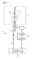
- a general schematic block diagram of a one-dimensional apparatus for optical tomography;
- Figure 2
- a general schematic block diagram of an apparatus for optical tomography with a linear filter array incorporating also a linear array of light sources;
- Figure 3
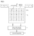
- schematically a cross-sectional view on a filter array incorporating also an array of light sources;
- Figure 4
- the basic principle to the measurement of the light intensity of a backscattered photon beam;
- Figure 5
- a possible 2D implementation of the block of lasers in the matrix in
Fig.3 and inFig.4 ; - Figure 6
- a possible realization of an optical multi-detection unit of an optical multi-detection and measurement system;
- Figure 7
- schematically a structural implementation of an apparatus for optical tomography; and
- Figure 8
- schematically a realization for an apparatus for optical tomography.
- The general block-schematic of an one-dimensional (1D) apparatus A for optical tomography, preferably based on the method for optical tomography as filed with the European Patent application
08014407.4 on August 13, 2008 Fig.1 . According toFig.1 , aturbid medium 1, containing (or not containing) aninclusion 2 is illuminated through acontact surface 3 in the coordinate point x=0 by a collimated optical beam 4 emitted along an optical axis z from alaser source 5, driven by thelaser driver 6. A specific backscattered photon beam 7, which is parallel to the optical axis z, is optically linked after passing thecontact surface 3 through an optical detection andmeasurement block 8 with a computer andalgorithms block 9. - The operation of the apparatus A in
Fig.1 , based on the method for optical tomography mentioned above is as follows. The input collimated optical radiation 4 begins to scatter immediately after entering theturbid medium 1 through thecontact surface 3. As a result of the multiple scattering, theturbid medium 1 containing theinclusion 2 will be illuminated within a spread angle γ. A part of this radiation 4, backscattered in parallel to the optical axis z contains, after passing thecontact surface 3, the specific photon beam 7, which is then optically detected and measured by the optical detection andmeasurement block 8. The amplitude of the output signal (at x coordinates jx = 0 of the laser beam, kx of the specific photon beam 7 and px of theinclusion 2, at a depth pz of the inclusion) can be denoted by

- In the last expressions the output signal is represented as depending on the discrete coordinates kx , along the x - axis of the positions of the specific photon beams 7, given by xk = kx Δ x , where kx =1...K x , and Kx Δ k is the maximum tolerable distance between the laser beam 4 and the specific backscattered photon beams 7. The step Δ k is defined as the minimum distance between the adjacent non-overlapped specific photon beams along the x -axis.
- By disposing the optical detector in the optical detection and
measurement block 8 in Kx successive positions kx along the x - axis, one can create the set of output signals

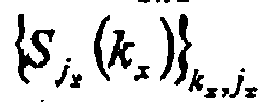
- Then, according to the method for optical tomography, one can calculate (in block 9) the coordinates of the
inclusion 2 and the optical characteristics of theturbid medium 1 and theinclusion 2. - Further considering now in
Fig.2 a set of Kx parallel specific backscattered beams 71.....7 Kx , disposed at the corresponding positions as inFig.1 , each one linked to a corresponding detector of the set of Kx optical detectors in an optical multi-detection andmeasurement system 10, and a set of Jx emitting lasers 51..,5 Jx , disposed also along the x - axis with a step Δ j = mΔ k , m > 1, each one driven by a corresponding driver of theset 61...6 Jx in theblock 6. - The operation of the apparatus in
Fig.2 , based on the method for optical tomography and the apparatus A inFig.1 is as follows. In each moment one of the emitting lasers (say, jx ) of theset 51...5 Jx is switched to an "ON" state, while all other lasers are kept in an "OFF" state. The optical detectors in the optical multi-detection andmeasurement system 10 are always in the "ON" condition. Each of these optical detectors will measure the optical powers from the corresponding specific backscattered photon beams 71.....7 Kx . In this way the entire set of output signals
Fig.1 , without successive positioning of any single optical detector in the optical detection andmeasurements system 8. - Then, the emitting laser is switched "OFF" and the next laser jx +1 will switch "ON", while all other lasers remain in "OFF" state. The optical detectors in the optical multi-detection and
measurement system 10 remain in the "ON" state. The recorded set of output signals for this case will be


inclusion 2 and the optical characteristics of theturbid medium 1 and theinclusion 2, will be created after successive switching in "ON" state the entire set of emittinglasers 51...5 Jx . At this implementation all the elements of the apparatus remain unmoved. Moreover, the full measurement time can be thus minimized. - In the following a 2D-implementation of the apparatus for optical tomography according the
Fig.1 andFig.2 is considered. It is given as a cross-sectional view inFig.3 , where the disposition of the two dimensional set (a matrix) oflasers 51...5 Jx ,51,...5 Jy and a matrix of specific backscattered photon beams 71...7 Kx ,71...7 Ky on the contact surface is represented. According toFig.3 , the space step Δ j of the laser dispositions along both the coordinates is chosen to be larger (Δ j = 3Δ k ) than the step Δ k of specific backscattered photon beams 71...7 Kx ,71...7 Ky . Moreover, the two-dimensionaloptical multi-detector system 11 contains a two-dimensional set of optical detectors, each one linked to the corresponding specific backscattered photon beams of the set 71...7 Kx ,71...7 Ky . - The operation of the two dimensional apparatus in
Fig.3 is similar to that of the one dimensional apparatus inFig.2 . In each moment one of the lasers in thelaser matrix 51...5 Jx ,51...5 Jy is in "ON" state, while all other lasers are switched to "OFF" state. Then, the next laser in the matrix will be switched to "ON" state, while all other lasers are switched to "OFF" state. The two dimensional matrix 71...7 Kx ,71...7 Ky of optical detectors remains always in "ON" state. As evident, the entire set of output signals will be given now by

- This is the necessary set of signals to calculate (block 9) the 3D coordinates (two lateral ones and the depth) of the inclusion and the optical characteristics of the
medium 1 and theinclusion 2. At this implementation all elements of the apparatus remain unmoved. Moreover, the full measurement time can be thus minimized. - The numbers Nlasers of lasers in 51...5 J
x ,51...5 Jy and N det of optical detectors in 71...7 Kx ,71...7 Ky of the matrix inFig.3 can be determined by the following expressions (assuming symmetric implementation along both the lateral coordinates):

where L is the number of lasers along one of the axes from the coordinate origin to the end of the matrix, M is the total number of lasers plus detectors along one of the axis from the coordinate origin to the end of the matrix. According toFig.5 (L = 1, M = 6) one will obtain Nlasers = 9 and Ndet = 169. -
Fig.4 represents one possible implementation of the key block K, providing forming of the specific backscattered photon beam 7, which is parallel to the optical axis z. According toFig.4 , the formation of the backscattered photon beam 7 is realized by spatial filtering of scattered radiation using a tinycylindrical tube 12 of internal diameter dtube and length ltube and anoptical fiber 13. Thetiny tube 12 is disposed with one of its edges near the laser beam 4 with an axis, parallel to the laser beam. Theoptical fiber 13 is inserted with one of its edges into the opposite (rear) edge of thetube 12, while the other fiber edge is fed to the optical detector of the optical detection & measuringsystem 8. - The length ltube of the
tube 12 is assumed to be too long with respect to the internal diameter dtube , i.e. dtube << ltube. The basic function of tubes is to provide the very narrow field of view for the photon detection. The tube angle of view θ tube could be approximately determined by the expression θ tube ∼ dtube /ltube (say, for dtube ∼ 0.1 cm and ltube ∼ 5 cm we obtain that the tube field of view will be of the order of θ tube ∼ 20 mrad). For an inclusion depths pz ∼ 6 cm, the lateral receiving spot diameter will be of the order of 1.5 mm and thus, the overlapping of adjacent specific backscattered photon beams 7 can be easily avoided. Under these conditions one could neglect the mutual penetrations of the scattered light from adjacent parallel cylindrical volumes. The angular filtering can be improved by deposition of some absorbing coating on the internal wall of thetube 12. Moreover, for increasing the photon collection inside thetube 12, one can modify the receiving fibre edge surface, say, by forming a lens surface. The optical energy, passing through thetube 12 and thefiber 13 will create the signals, necessary to determine the position of theinclusion 2 and the optical characteristics of theturbid medium 1 and theinclusion 2. - The set of specific backscattered photon beams for the 2D implementation of the apparatus can be formed (according to
Figures 2 and3 ) by a set of paralleltiny tubes 121...12 Kx ,121...12 Ky with correspondingoptical fibers 131...13 Kx ,131...13 Ky . The outputs ofoptical fibers 131...13 Kx ,131...13 Ky are fed to corresponding optical detectors, disposed within the multi-channel optical detection andmeasurements system 11. The distance between the adjacenttiny tubes 12 will be equal to the step of the matrix inFig.3 . In this case the matrix inFig. 3 is formed by the open edges oftubes 121...12 Kx ,121...12 Ky andlasers 51...5 Jx ,51...5 Jy . At these configurations the full set of output signals

-
Fig.5 presents a possible 2D implementation of the block of lasers in the matrix inFig.3 and inFig.4 . According toFig.5 , the emitted radiation from the two-dimensional block oflasers 51...5 Jx ,51...5 Jy (as inFig.3 ) is directed into the optical fibers 141...14 Jx ,141...14 Jy . Lenses 151...15 Jx ,151...15 Jy are disposed on the opposite fiber edges (in some other configuration the lenses 151...15 Jx ,151...15 Jy are implemented on the fiber edges). The use of lenses 15 provides an emission of collimated laser beams into theturbid medium 1. - The
optical bunch 16 contains thefibers 131...13 Kx ,131...13 Ky of the receiving part of the apparatus and the fibers 141...14 Jx ,141...14 Jy of the emitting part. The optical detectors within the multi-channel optical detection andmeasurement system 11 are correspondingly linked with thefibers 131...13 Kx ,131...13 Ky . Moreover, the optical fibers 141...14 Jx ,141...14 Jy in the emitting part are correspondingly linked with thelasers 51...5 Jx 51...5 Jy . - The configuration of the apparatus in
Fig.5 provides electrical separation of the apparatus as a whole from thecontact surface 3 that is connected mechanically with the patient, in particular which is the skin of the patient. - One possible realization of the optical multi-detection unit of the optical multi-detection and
measurement system 11 is shown inFig.6 . Here the properly in space arranged set of edges offibers 131...13 Kx ,131...13 Ky illuminates asurface 17 of a photosensitive matrix (say, CCD-matrix, intensifier photosensitive surface, etc.). The special arrangement offibers 13 is chosen by the condition that the corresponding light spots 181...18 Kx ,181...18 Ky , created by each of thefibers 13 be non-overlapped. Under these conditions the set of optical detectors in the opticalmulti-detection measurement system 11 is replaced by a single photosensitive matrix. The energies in the set of light spots on the single photosensitive matrix are proportional to the corresponding output signals

inclusion 2 and the optical characteristics of theturbid medium 1 and theinclusion 2. Measuring, by the use of CCD-optical receiver the set of above signals, one can essentially reduce the implementation of the apparatus. - One of the implementations of the apparatus for optical tomography can be realized using the block-schematic in
Fig. 7 . Here the optomechanical matrix (according to realizations inFig.5 and Fig.6 ) is in contact with patients. It is well known that the patient breast tissue can be considered as a turbid medium. Theoptomechanical matrix 19 illuminates the patient breast tissue (containing, say, some cancer-type inclusions). The backscattered radiation formed in a set of parallel photon beams (seeFig.4 andFig.5 ) is transformed (seeFig.6 ) in a set of arranged light spots of defined energies. Then, the set of spots is transformed further by a receiving electronics/amplification/recording block 20 into a set of signals. The recorded set of signals

processor block 22. The output results are imaged at least on a monitor together with the information about the inclusion coordinates and their optical characteristics. This information is further processed in order to determine the specificity of the inclusions. - Then, one possible implementation of the apparatus A as a whole is given in
Fig.8 for illustration. The basic block of this apparatus demonstrates the principal opportunity to use both the method and the apparatus for creation of miniature instruments for future applications in medical practice.
Claims (11)
- Apparatus (A) for determining optical and spatial characteristics of an inclusion (2) in a turbid medium (1) using multiple-scattering optical tomography, comprising:a) a matrix of light sources (5), each light source (5) emitting a collimated laser incident radiation (4) along an optical axis (z),b) a filter matrix (K, 12, 13) spatially filtering a totality of backscattered secondary photon beams (7), the filter matrix (K, 12, 13) being arranged to yield a number of back scattered photon beams having a substantially parallel orientation to the optical axis (z),c) an array (17) of detector elements, each detector element detecting an optical output power of said back scattered photon beams (7),d) a control unit (9, 21, 22) for computing the spatial characteristics of the inclusion (2) based on the spatial distribution of the detected optical output power of said back scattered photon beams (7).
- Apparatus (A) according to claim 1, whereby the control unit (9, 21, 22) is further enabled:a) to determine a contrast and a sign of said contrast of the inclusion (2), based on a comparison of the spatial distribution of the optical output power of said back scattered photon beams (7) for the turbid medium (1) without the inclusion (2) and the spatial distribution of the optical output power of said back scattered photon beams (7) for the turbid medium (1) comprising the inclusion (2), andb) to compute the optical characteristics of the inclusion (2) and of the turbid medium (1) based on the spatial characteristics and the spatial distribution of the optical output power of said backscattered photon beams (7) for the turbid medium (1) comprising the inclusion (2).
- Apparatus (A) according to claim 1 or 2, whereby the filter matrix (K, 12, 13) comprises a number of distributed tube-like filter channels (12), said distributed tube-like filter channels (12) being oriented parallel to each other along the direction of the optical axis (z) in order to reject and/or to absorb all particular backscattered photon beams which lack the substantial parallel orientation to the optical axis (z).
- Apparatus (A) according to claim 3, whereby said filter channels are formed as cylindrical apertures (12) within a filter block (K), said cylindrical apertures (12) being oriented parallel to the optical axis (z).
- Apparatus (A) according to any of the preceding claims, wherein each light source (5) emits its collimated laser incident radiation (4) along the optical axis (z), each of the radiations originating from a different continuous wave laser (6).
- Apparatus (A) according to claim 5, wherein the filter matrix hosts the array of light sources (5), thereby comprising an even distribution of the detector elements and light sources (5) as seen in the cross-sectional area oriented perpendicular to the optical axis (z).
- Apparatus (A) according to claim 6, wherein the number of detector elements is at least twice as big as the number of light sources (5).
- Apparatus (A) according to claim 6 or 7, wherein the detector elements and the light sources (5) are disposed in regular chessboard-like pattern whereby each light source (5) comprises at least four exclusive detector elements juxtaposed.
- Apparatus (A) according to claim 6, 7 or 8, wherein the output light spots of the tube-like filter channels (12) are spatially arranged in a non-overlapping configuration and optically linked to a corresponding array of detector elements (17) formed as non-overlapping areas of adjacent pixels of a single photosensitive matrix.
- Apparatus (A) according to any of the preceding claims, wherein the light sources (5) are controlled by the control unit (9, 21, 22); said control unit (9, 21, 22) allowing the light sources (5) to emit one after the other and only one at a time.
- Apparatus (a) according to claim 10, wherein the control unit (9, 21, 22) is collecting the detected optical output power in response to each of the emitted collimated laser incident radiations (4).
Priority Applications (1)
| Application Number | Priority Date | Filing Date | Title |
|---|---|---|---|
| EP08019605A EP2165647A1 (en) | 2008-08-13 | 2008-11-10 | Apparatus for determining optical and spatial characteristics of an inclusion in a turbid medium using multiple-scattering optical tomography |
Applications Claiming Priority (2)
| Application Number | Priority Date | Filing Date | Title |
|---|---|---|---|
| EP08014407A EP2153772A1 (en) | 2008-08-13 | 2008-08-13 | Method for determining optical and spatial characteristics of an inclusion in a turbid medium using multiple-scattering optical tomography |
| EP08019605A EP2165647A1 (en) | 2008-08-13 | 2008-11-10 | Apparatus for determining optical and spatial characteristics of an inclusion in a turbid medium using multiple-scattering optical tomography |
Publications (1)
| Publication Number | Publication Date |
|---|---|
| EP2165647A1 true EP2165647A1 (en) | 2010-03-24 |
Family
ID=40225545
Family Applications (2)
| Application Number | Title | Priority Date | Filing Date |
|---|---|---|---|
| EP08014407A Withdrawn EP2153772A1 (en) | 2008-08-13 | 2008-08-13 | Method for determining optical and spatial characteristics of an inclusion in a turbid medium using multiple-scattering optical tomography |
| EP08019605A Ceased EP2165647A1 (en) | 2008-08-13 | 2008-11-10 | Apparatus for determining optical and spatial characteristics of an inclusion in a turbid medium using multiple-scattering optical tomography |
Family Applications Before (1)
| Application Number | Title | Priority Date | Filing Date |
|---|---|---|---|
| EP08014407A Withdrawn EP2153772A1 (en) | 2008-08-13 | 2008-08-13 | Method for determining optical and spatial characteristics of an inclusion in a turbid medium using multiple-scattering optical tomography |
Country Status (1)
| Country | Link |
|---|---|
| EP (2) | EP2153772A1 (en) |
Citations (5)
| Publication number | Priority date | Publication date | Assignee | Title |
|---|---|---|---|---|
| US4948974A (en) * | 1984-06-25 | 1990-08-14 | Nelson Robert S | High resolution imaging apparatus and method for approximating scattering effects |
| US5747789A (en) * | 1993-12-01 | 1998-05-05 | Dynamics Imaging, Inc. | Method for investigation of distribution of physiological components in human body tissues and apparatus for its realization |
| US6353753B1 (en) * | 1998-05-05 | 2002-03-05 | Stephen Thomas Flock | Optical imaging of deep anatomic structures |
| US20040030255A1 (en) * | 2002-06-05 | 2004-02-12 | Research Foundation Of City University | Hybrid-dual-Fourier tomographic algorithm for a fast three-dimensional optical image reconstruction in turbid media |
| WO2008011112A2 (en) * | 2006-07-19 | 2008-01-24 | University Of Connecticut | Method and apparatus for medical imaging using combined near-infrared optical tomography, fluorescent tomography and ultrasound |
Family Cites Families (3)
| Publication number | Priority date | Publication date | Assignee | Title |
|---|---|---|---|---|
| US4555179A (en) * | 1982-11-08 | 1985-11-26 | John Langerholc | Detection and imaging of objects in scattering media by light irradiation |
| US4810875A (en) * | 1987-02-02 | 1989-03-07 | Wyatt Technology Corporation | Method and apparatus for examining the interior of semi-opaque objects |
| US7551950B2 (en) * | 2004-06-29 | 2009-06-23 | O2 Medtech, Inc,. | Optical apparatus and method of use for non-invasive tomographic scan of biological tissues |
-
2008
- 2008-08-13 EP EP08014407A patent/EP2153772A1/en not_active Withdrawn
- 2008-11-10 EP EP08019605A patent/EP2165647A1/en not_active Ceased
Patent Citations (5)
| Publication number | Priority date | Publication date | Assignee | Title |
|---|---|---|---|---|
| US4948974A (en) * | 1984-06-25 | 1990-08-14 | Nelson Robert S | High resolution imaging apparatus and method for approximating scattering effects |
| US5747789A (en) * | 1993-12-01 | 1998-05-05 | Dynamics Imaging, Inc. | Method for investigation of distribution of physiological components in human body tissues and apparatus for its realization |
| US6353753B1 (en) * | 1998-05-05 | 2002-03-05 | Stephen Thomas Flock | Optical imaging of deep anatomic structures |
| US20040030255A1 (en) * | 2002-06-05 | 2004-02-12 | Research Foundation Of City University | Hybrid-dual-Fourier tomographic algorithm for a fast three-dimensional optical image reconstruction in turbid media |
| WO2008011112A2 (en) * | 2006-07-19 | 2008-01-24 | University Of Connecticut | Method and apparatus for medical imaging using combined near-infrared optical tomography, fluorescent tomography and ultrasound |
Also Published As
| Publication number | Publication date |
|---|---|
| EP2153772A1 (en) | 2010-02-17 |
Similar Documents
| Publication | Publication Date | Title |
|---|---|---|
| EP0647120B1 (en) | Examination of subjects using photon migration with high directionality techniques | |
| US4303860A (en) | High resolution radiation detector | |
| US5999836A (en) | Enhanced high resolution breast imaging device and method utilizing non-ionizing radiation of narrow spectral bandwidth | |
| US9709733B2 (en) | Hand-held optical probe based imaging system with 3D tracking facilities | |
| US7023558B2 (en) | Acousto-optic monitoring and imaging in a depth sensitive manner | |
| US6240305B1 (en) | Method and apparatus for measuring absorption information of a scattering medium | |
| EP0956496B1 (en) | Method and apparatus for detecting an object | |
| WO2009073979A1 (en) | Three-dimensional photoacoustic imager and methods for calibrating an imager | |
| WO2006116701A2 (en) | Imaging systems and methods to improve backscattering imaging using circular polarization memory | |
| US10121561B2 (en) | Collimator for X-ray diffraction spectroscopy, associated device and its use | |
| WO1999037994A1 (en) | Multiple diameter fiber optic device and process of using the same | |
| US7692160B2 (en) | Method and system of optical imaging for target detection in a scattering medium | |
| EP2732756B1 (en) | Object information acquisition apparatus | |
| CN103237489B (en) | probe | |
| JP2005536741A (en) | Apparatus for detecting backscatter in laser-based blood analysis systems | |
| Bérubé-Lauzière et al. | Time-resolved fluorescence measurements for diffuse optical tomography using ultrafast time-correlated single photon counting | |
| JP2007082769A (en) | Sample analyzer | |
| JP4647447B2 (en) | Sample analyzer | |
| WO2020130969A1 (en) | A laser diffuse optical tomography device used in back projection geometry | |
| EP2153772A1 (en) | Method for determining optical and spatial characteristics of an inclusion in a turbid medium using multiple-scattering optical tomography | |
| CN121667645B (en) | A tumor detection device and method based on a diamond quantum sensor | |
| JPH0483149A (en) | Fluorescent image imaging device | |
| JP2832338B2 (en) | Method and apparatus for measuring optical properties of light scattering objects | |
| Vasefi et al. | Angular domain imaging for tissue mapping | |
| JPH0781948B2 (en) | Optical CT device |
Legal Events
| Date | Code | Title | Description |
|---|---|---|---|
| PUAI | Public reference made under article 153(3) epc to a published international application that has entered the european phase |
Free format text: ORIGINAL CODE: 0009012 |
|
| AK | Designated contracting states |
Kind code of ref document: A1 Designated state(s): AT BE BG CH CY CZ DE DK EE ES FI FR GB GR HR HU IE IS IT LI LT LU LV MC MT NL NO PL PT RO SE SI SK TR |
|
| AX | Request for extension of the european patent |
Extension state: AL BA MK RS |
|
| 17P | Request for examination filed |
Effective date: 20100906 |
|
| 17Q | First examination report despatched |
Effective date: 20101011 |
|
| AKX | Designation fees paid |
Designated state(s): AT BE BG CH CY CZ DE DK EE ES FI FR GB GR HR HU IE IS IT LI LT LU LV MC MT NL NO PL PT RO SE SI SK TR |
|
| RAP1 | Party data changed (applicant data changed or rights of an application transferred) |
Owner name: SIEMENS AKTIENGESELLSCHAFT |
|
| RAP1 | Party data changed (applicant data changed or rights of an application transferred) |
Owner name: SIEMENS HEALTHCARE GMBH |
|
| STAA | Information on the status of an ep patent application or granted ep patent |
Free format text: STATUS: EXAMINATION IS IN PROGRESS |
|
| STAA | Information on the status of an ep patent application or granted ep patent |
Free format text: STATUS: THE APPLICATION HAS BEEN REFUSED |
|
| 18R | Application refused |
Effective date: 20180312 |