EP2165558B1 - Buffer status reporting - Google Patents
Buffer status reporting Download PDFInfo
- Publication number
- EP2165558B1 EP2165558B1 EP08765826A EP08765826A EP2165558B1 EP 2165558 B1 EP2165558 B1 EP 2165558B1 EP 08765826 A EP08765826 A EP 08765826A EP 08765826 A EP08765826 A EP 08765826A EP 2165558 B1 EP2165558 B1 EP 2165558B1
- Authority
- EP
- European Patent Office
- Prior art keywords
- buffer status
- buffer
- status report
- data
- absolute
- Prior art date
- Legal status (The legal status is an assumption and is not a legal conclusion. Google has not performed a legal analysis and makes no representation as to the accuracy of the status listed.)
- Active
Links
Images


Classifications
-
- H—ELECTRICITY
- H04—ELECTRIC COMMUNICATION TECHNIQUE
- H04L—TRANSMISSION OF DIGITAL INFORMATION, e.g. TELEGRAPHIC COMMUNICATION
- H04L47/00—Traffic control in data switching networks
- H04L47/10—Flow control; Congestion control
-
- H—ELECTRICITY
- H04—ELECTRIC COMMUNICATION TECHNIQUE
- H04L—TRANSMISSION OF DIGITAL INFORMATION, e.g. TELEGRAPHIC COMMUNICATION
- H04L47/00—Traffic control in data switching networks
- H04L47/10—Flow control; Congestion control
- H04L47/26—Flow control; Congestion control using explicit feedback to the source, e.g. choke packets
- H04L47/263—Rate modification at the source after receiving feedback
-
- H—ELECTRICITY
- H04—ELECTRIC COMMUNICATION TECHNIQUE
- H04L—TRANSMISSION OF DIGITAL INFORMATION, e.g. TELEGRAPHIC COMMUNICATION
- H04L47/00—Traffic control in data switching networks
- H04L47/10—Flow control; Congestion control
- H04L47/30—Flow control; Congestion control in combination with information about buffer occupancy at either end or at transit nodes
-
- H—ELECTRICITY
- H04—ELECTRIC COMMUNICATION TECHNIQUE
- H04W—WIRELESS COMMUNICATION NETWORKS
- H04W28/00—Network traffic management; Network resource management
- H04W28/02—Traffic management, e.g. flow control or congestion control
-
- H—ELECTRICITY
- H04—ELECTRIC COMMUNICATION TECHNIQUE
- H04W—WIRELESS COMMUNICATION NETWORKS
- H04W72/00—Local resource management
- H04W72/20—Control channels or signalling for resource management
- H04W72/21—Control channels or signalling for resource management in the uplink direction of a wireless link, i.e. towards the network
-
- H—ELECTRICITY
- H04—ELECTRIC COMMUNICATION TECHNIQUE
- H04W—WIRELESS COMMUNICATION NETWORKS
- H04W8/00—Network data management
- H04W8/02—Processing of mobility data, e.g. registration information at HLR [Home Location Register] or VLR [Visitor Location Register]; Transfer of mobility data, e.g. between HLR, VLR or external networks
- H04W8/04—Registration at HLR or HSS [Home Subscriber Server]
-
- H—ELECTRICITY
- H04—ELECTRIC COMMUNICATION TECHNIQUE
- H04W—WIRELESS COMMUNICATION NETWORKS
- H04W8/00—Network data management
- H04W8/22—Processing or transfer of terminal data, e.g. status or physical capabilities
-
- H—ELECTRICITY
- H04—ELECTRIC COMMUNICATION TECHNIQUE
- H04W—WIRELESS COMMUNICATION NETWORKS
- H04W28/00—Network traffic management; Network resource management
- H04W28/02—Traffic management, e.g. flow control or congestion control
- H04W28/10—Flow control between communication endpoints
- H04W28/12—Flow control between communication endpoints using signalling between network elements
Definitions
- the present invention relates to the reporting of buffer status in mobile telecommunications networks, particularly but not exclusively networks operating according to the 3GPP standards or equivalents or derivatives thereof.
- UE User Equipment
- eNodeB base station
- HSUPA High-Speed Uplink Packet Access
- buffer status reporting can be applied to other systems, e.g. other CDMA or wireless in which a mobile device or User Equipment (UE) communicates with one of several other devices (corresponding to eNodeB) with the corresponding elements of the system changed as required.
- UE User Equipment
- the 3GPP contribution Enhancement to buffer status reporting 3GPP TSG-RAN WG2#57bis R2-071345 discloses also an improvement of the efficiency of transmission of buffer status information from a mobile communication device to an eNode B.
- the method starts with a synchronised buffer status between the eNode B and the mobile communication device, i.e. at a certain time, the mobile communication indicates its actual buffer size to the eNode B. Then, the eNode B assumes a decrease of the buffer size of the communication device.
- the mobile communication device is aware of this estimated decrease and will transmit only the difference between this estimation and the actual buffer size, i.e. the mobile communication device will only transmit a relative buffer status report. There is no disclosure of a transmission of an absolute buffer status report or a relative status report depending on the current buffer status information.
- the present invention provides a method of signalling buffer status information from a mobile device to a base station, the method comprising: determining current buffer status information for the mobile device; determining a relationship between the current buffer status information and one or more defined criteria; and sending an absolute buffer status report, indicating the current buffer status, or a relative buffer status report, indicating a change in the buffer status since a previous buffer status report, to the base station in dependence upon the determined relationship.
- the buffer status information used in determining the relationship may comprise, for example, the amount of data currently held in the buffer or the rate at which data is being written into the buffer.
- the reports sent may include the same type of buffer status data or different types of buffer status data as the data used for determining the relationship.
- the relationship determined may be a determination that the buffer status information is within certain limits or that it is greater or less than some defined value. For example, if the current buffer status information comprises the change of rate at which data is being written into the buffer since a previous measurement, then the relationship that is determined may be whether the current buffer status information is above or below the defined change of rate.
- the relative buffer status report may indicate the change in the amount of data held within the buffer since the previous buffer status report or a change of the rate at which data is being written into the buffer since the previous buffer status report.
- the relative buffer status report indicates a change in the buffer status since the last transmitted absolute buffer status report, as this avoids the propagation of errors that might otherwise result.
- the method may also comprise the step of differencing the current buffer status information and the buffer status information corresponding to the last absolute buffer status report, to determine the change in the buffer status since the last transmitted absolute buffer status report.
- the mobile communications device can transmit different types of data at the same time and wherein the buffer status reports include buffer status information for each type of data.
- Each type of data is preferably associated with a radio bearer group and the buffer status reports include buffer status information for each radio bearer group. This allows the base station to be able to allocate the uplink resources (used for communicating data from the mobile communications device to the base station) based not only on the amount of data in the buffer, but also on the relative priority associated with different traffic types.
- the invention provides, for all methods disclosed, corresponding computer programs or computer program products for execution on corresponding equipment, the equipment itself (user equipment, nodes or components thereof) and methods of updating the equipment.
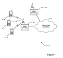
- Figure 1 schematically illustrates a mobile (cellular) telecommunication system 1 in which users of mobile telephones (MT) 3-0, 3-1, and 3-2 can communicate with other users (not shown) via one of the base stations 5-1 or 5-2 and a telephone network 7.
- a number of uplink and downlink communications resources are available for the wireless link between the mobile telephones 3 and the base stations 5.
- the base stations 5 allocate downlink resources to each mobile telephone 3 depending on the amount of data to be sent to the mobile telephone 3.
- the base stations 5 allocate uplink resources to each mobile telephone 3 depending on the amount and type of data the mobile telephone 3 has to send to the base station 5.
- each mobile telephone 3 sends regular buffer status reports to its base station 5, informing the base station 5 of the amount and type of data it has in its buffers for transmission.
- the mobile telephones 3 are arranged to send two types of buffer status reports:
- FIG. 2 is a block diagram illustrating the main components of each of the base stations 5 used in this embodiment.
- each base station 5 includes a transceiver circuit 21 which is operable to transmit signals to and to receive signals from the mobile telephones 3 via one or more antennae 23 and which is operable to transmit signals to and to receive signals from the telephone network 7 via a network interface 25.
- a controller 27 controls the operation of the transceiver circuit 21 in accordance with software stored in memory 29.
- the software includes, among other things, an operating system 31, a resource allocation module 33 and a downlink scheduler 35.
- the resource allocation module 33 is operable to allocate the above described communications resources for the uplink and downlink communications to each mobile telephone 3 and the downlink scheduler schedules the transmission of the downlink data to each mobile telephone 3 based on the allocated resources.
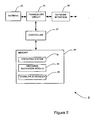
- FIG 3 is a block diagram illustrating the main components of each of the mobile telephones 3 shown in Figure 1 .
- the mobile telephones 3 include a transceiver circuit 71 that is operable to transmit signals to and to receive signals from the base station 5 via one or more antennae 73.
- the mobile telephone 3 also includes a controller 75 which controls the operation of the mobile telephone 3 and which is connected to the transceiver circuit 71 and to a loudspeaker 77, a microphone 79, a display 81, and a keypad 83.
- the controller 75 operates in accordance with software instructions stored within memory 85. As shown, these software instructions include, among other things, an operating system 87, an uplink scheduler 89 and a buffer status reporting module 90.
- the memory also provides an uplink data buffer 91.
- the uplink scheduler 89 is responsible for scheduling the transmission of the uplink data from the buffer 91 in accordance with the resources allocated to the mobile telephone 3 for its uplink transmissions by the base station 5; and the buffer status reporting module 90 is responsible for determining and signalling buffer status information to the base station.
- the base station 5 and the mobile telephones 3 are described for ease of understanding as having discrete resource allocation, scheduling and buffer status reporting modules. Whilst these modules may be provided in this way for certain applications, for example where an existing system has been modified to implement the invention, in other applications, for example in systems designed with the inventive features in mind from the outset, these modules may be built into the overall operating system or code and so these modules may not be discernible as discrete entities.
- Figure 4 illustrates part of a protocol stack (lower three layers) used in the mobile telephones 3 and the base stations 5.
- the first layer is the physical layer (L1) which is responsible for the actual transmission of the data over the radio communication channel.
- the second layer (L2) which is divided into three sub-layers - the Medium Access Control layer (L2/MAC) which is responsible for controlling access to the air interface; the Outer ARQ layer (L2/OARQ) which is responsible for concatenation and segmentation of data packets, the acknowledgment of packets and the re-transmission of data packets where necessary; and the PDCP layer (L2/PDCP) which is responsible for header compression and ciphering.
- L2/MAC Medium Access Control layer
- L2/OARQ Outer ARQ layer
- L2/PDCP PDCP layer
- the second layer is the Radio Resource Control (RRC) layer (L3/RRC) that is responsible for controlling radio resources used in the air interface between the base station 5 and the mobile telephone 3.
- RRC Radio Resource Control
- L2/Outer ARQ layer includes a number of Outer ARQ entities 95 used to manage the transmission of C-plane data and U-plane data
- the L2/PDCP layer includes PDCP entities 97 used to process the C-plane and the U-plane data.
- FIG 4 also shows the radio bearers 98 assigned to each source of data to be transmitted.
- the radio bearers are also grouped into groups depending on their data types. For example, the user may be using software on the mobile telephone 3 to upload a photograph to a website on the Internet and at the same time, he may be downloading a file from a network server.
- a respective radio bearer would be associated with each task and in this case, as they both relate to FTP (File Transfer Protocol), the two radio bearers would be in the same radio bearer group. If the user then makes a voice call, then another radio bearer (belonging to another radio bearer group) will be used to control the data transmission and reception for the voice call.
- FTP File Transfer Protocol
- the communication resources allocated by the base station 5 for the uplink are shared between the radio bearers 98, depending on their assigned priorities and data rates.
- the RRC layer 96 sets the data rate and priority for each radio bearer 98.
- the uplink scheduler 89 then controls the scheduling of the data packets of each radio bearer 98 for transmission based on the data rates and priorities assigned to the radio bearers by the RRC layer 96.
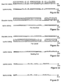
- Figures 5a to 5f for different types of data, where the amount of data is represented by the height of the plot.
- Figure 5a illustrates a typical model of data transmissions for HTTP traffic
- Figure 5b illustrates a typical model of data transmissions for FTP file download traffic
- Figure 5c illustrates a typical model of data transmissions for FTP file upload traffic
- Figure 5d illustrates a typical model of data transmissions for multimedia video sharing traffic
- Figure 5e illustrates a typical model of data transmissions for multimedia messaging/multiplayer games/push to talk traffic
- Figure 5f illustrates a typical model of data transmissions for VoIP traffic.
- the base station 5 in order to try to optimise the allocation of the uplink resources at any point in time, the base station 5 (and in particular the resource allocation module 33) dynamically adjusts the resources allocated to each mobile telephone 3 based on their needs.
- the uplink data associated with each radio bearer 98 Prior to being transmitted, the uplink data associated with each radio bearer 98 is buffered in the uplink transmission buffer 91. Therefore, as the data rates change, the buffer 91 will fill or empty, depending on the difference between the resources needed and the resources currently allocated. Consequently, by signalling the amount of data in the buffer 91 to the base station 5, the base station 5 can dynamically adjust the resources allocated to each mobile telephone 3.
- the buffer status reports transmitted by the mobile telephones 3 include the buffer status for each of the different groups of radio bearers 98.
- the base station 5 will know, for each mobile telephone 3 that it is servicing, how much HTTP web browsing traffic the telephone 3 has to transmit; how much FTP traffic the telephone 3 has to transmit; how much multimedia video sharing traffic the telephone 3 has to transmit; how much VoIP traffic the telephone 3 has to transmit etc.
- the base station 5 can therefore allocate the available uplink resources amongst all the mobile telephones 3 based on the priority associated with the data each mobile telephone 3 has to transmit.
- the inventor has appreciated that sending regular buffer status reports, each containing buffer status information for the different radio bearer groups, would require a significant signalling overhead and is unnecessary for a large part of the time as there are sustained periods in which the bit rates remain fairly constant. Therefore, the inventor proposes that the mobile telephones 3 send two types of buffer status reports - Absolute Buffer.Status Reports and Relative Buffer Status Reports.
- ABSSR Absolute Buffer Status Reports
- Absolute Buffer Status Reports would essentially be event triggered when the amount of data in the mobile telephone's buffer 91 (or alternatively in a traffic flow) gets above (or below) a predefined threshold value.
- Relative Buffer Status Reports will be of small size making it possible to piggyback the buffer status information in a data PDU (Protocol Data Unit) thereby considerably reducing the uplink overhead of sending Absolute Buffer Status Reports periodically for requesting uplink resources.
- the Relative Buffer Status Reports will include differential buffer status information for each radio bearer group, thereby allowing the base station 5 to be able to perform QoS aware uplink resource allocations between the mobile telephones 3 that it is servicing.
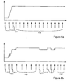
- FIGs 6a and 6b illustrate, respectively, an example use of Absolute and Relative Buffer Status Reports for a single service case (file upload) and a multiple service case (file upload + TCP/RLC acknowledgments for web browsing traffic).
- Absolute Buffer Status Reports 111 are sent at the start, when the application has just started and when the bit rate changes. Thereafter, Relative Buffer Status Reports 113 are sent periodically whilst the data rate remains fairly constant.
- Figure 6b because there are two user data sources (one a file upload and the other acknowledgements for received user data packets), the required data rate varies more over the illustrated period and so more Absolute Buffer Status Reports 111 are sent.
- the buffer status reporting module 90 determines whether to send an Absolute or a Relative Buffer Status Report by comparing the amount of data in the buffer 91 with a stored upper threshold (T U ) and a stored lower threshold (T L ). If the amount of data in the buffer is above the upper threshold or below the lower threshold, then the buffer status reporting module 90 will send an Absolute Buffer Status Report, otherwise it will send a Relative Buffer Status Report. As those skilled in the art will appreciate, in order to be able to calculate a Relative Buffer Status Report from the measured buffer status information, the buffer status reporting module 90 has to store the buffer status information transmitted in the last Absolute Buffer Status Report that was sent, and this information is stored in the memory 85.
- the base station 5 With regard to the operation of the base station 5 and in particular the resource allocation module 33, it will have to keep track of the Absolute Buffer Status Reports received from the various mobile telephones 3 that it is servicing and use them with the received Relative Buffer Status Reports to determine the current buffer status in each mobile telephone 3, so that it can perform the dynamic resource allocation.
- Relative Buffer Status Reports can encode the required information. For example, they can include a count of the number of bits more or less than the number of bits in the last transmitted Absolute Buffer Status Report or a percentage change (in say increments of 25%) since the last Absolute Buffer Status Report. Relative Buffer Status Reports could also include, for example:
- Relative Buffer Status Reports which indicate the change in buffer status relative to the last Relative Buffer Status Report. However, this is not preferred as if one Relative Buffer Status Report is lost (not received by the base station 5) then an error will propagate through the subsequent reports, until the next Absolute Buffer Status Report. When the relative reports are made relative to the last Absolute Buffer Status Report, lost status reports do not matter as the next Relative Buffer Status report will be correct.
- the mobile telephones 3 may decide whether to send an Absolute or a Relative Buffer Status Report.
- the buffer status reporting module 90 compared the amount of data in the buffer with upper and lower thresholds.
- the rate at which data is being written into the buffer 91 may be compared with upper and lower thresholds.
- the difference in the data rate or the difference in the actual amount of data stored in the buffer between a current time point and a previous time point may be compared with a defined value, with the result defining whether to send an Absolute or a Relative Buffer Status Report.
- the buffer status information used to determine whether to send an Absolute or a Relative Buffer Status Report may be different to the buffer status data included in the report. For example, the determination may be made based on the rate at which data is being written into the buffer 91, whilst the report may contain a count relating to the actual amount of data contained in the buffer 91 or a count relating to the change in the amount of data in the buffer 91, depending on if the report is an Absolute or a Relative Buffer Status Report.
- the operations of the base station 5 and of the mobile telephones 3 may be controlled by dedicated hardware circuits or by programmable controllers controlled by software.
- the software may be provided at the time of manufacture or subsequently installed after downloading the software from a remote site.
- the Relative Buffer Status Reports could also be utilized as an indication to the base station 5 to switch from a talk spurt period to a silent period and vise versa for the VoIP service. Based on this indication from mobile telephone 3, the base station 5 can release persistently allocated uplink resources when switching from a talk spurt period to a silent period or re-allocate uplink resources when switching from a silent period to a talk spurt period.
- a source traffic model essentially consists of two parts: the arrival process for the user activities and the process describing the activity phase.
- the arrival process determines the instants when a user starts his activity. Such instants are denoted as arrival times. If WWW users are considered, the instant a user begins with his web browsing session is the arrival time for the HTTP application.
- the modeling approaches for the arrival process are not considered here and are assumed to be identical for the various applications for simplicity.
- the described traffic models are based on a general form of ON/OFF model where a session is generally composed of the some random number of ON/OFF periods described by the appropriate distribution. Each ON period will be further specified in terms of random number of packets, packets durations, packet itert-arrival times, etc.
- the traffic model assumes the steady maximum bit rate during the activity phase after the slow start.
- the delay components are illustrated in Figure 7 .
- Web browsing model in its simple form is an ON/OFF model where ON state represents the activity for fetching all objects belonging to one web request after accepting it and the OFF state represents a silence period after all objects in a web request are retrieved.
- the web traffic is essentially a downlink extensive with steady stream the TCP/ARQ acknowledgements in the uplink during the ON period as shown in Figure 8 .
- the FTP service can be included by describing an FTP file transfer like a web session with only one web request with prolonged active phase.
- the FTP file transfer is carried out in a manner illustrated in Figure 9 .
- Imaging service such as real time video sharing is about showing to the other end what is going on in your side of the phone connection.
- a lower bit rate limit is typically around 40 to 64 kbps for a duration varying from tens of seconds to few minutes.
- the resources could be persistently allocated, as shown in Figure 10 , however since the streaming traffic could fluctuate between MBR and GBR, we feel that it might be more efficient to allocate the resources dynamically.
- VoIP application will generate packets of constant size every 20ms during the talk spurt in a manner illustrated in Figure 12 .
- Multimedia messaging/multiplayer games/Push-to-Talk applications generate traffic burst that is unpredictable in nature and the exact buffer status is needed by the uplink eNB Scheduler to appropriately allocate resources.
- the packets are generated every 20ms sec during the talk spurt and the resources would be allocated in the semi static manner through persistent scheduling and therefore dynamic resource allocations for VoIP is not considered further in the paper.
- UE would include the buffer status of all the Radio Bearer Groups (RBG) in every report and would consequently incur overhead especially if there are many RBG.
- RBG Radio Bearer Groups
- Absolute Buffer Status Reports These would include the buffer status of all the Radio Bearer Groups and can be sent during the session start phase where the application has just started and the bit rate is changing in time before reaching a steady value. Absolute Buffer Status Reports would essentially be event triggered when the amount of data in the UE buffer (or alternatively in a traffic flow) gets above (or below) a predefined threshold value.
- Relative Buffer Status Reports These would include only differential buffer status (indicating a change in instantaneous bit rate) with respect to the last sent Absolute Buffer Status report and can be sent periodically when the applications have reached relatively steady bit rates.
- Relative Buffer Status reports will be of small size making it possible to piggyback the Buffer information in a data PDU thereby considerably reducing the uplink overhead of sending Absolute Buffer Status report periodically for requesting uplink resources.
- Relative Buffer Status Reports could include
- Relative Buffer Status Reports additionally to the Absolute Buffer Status Reports to reduce the signalling overhead for buffer status reporting in LTE.
- UE can smartly switch from Absolute to Relative Buffer Status Report after the application has attained steady bit rate.
- the use of Absolute to Relative Buffer Status Report for single and multiple service cases are illustrated to demonstrate the decrease in signalling overhead. With such schemes, the signalling overhead can be kept to acceptable limits without loss of granularity of information provided to the uplink eNB scheduler to perform QoS-aware scheduling.
- RBSR Relative Buffer Status Report
- UE in the next scheduled interval shall again report the differential with respect to the last ABSR or send ABSR if the buffer increases predefined threshold.
- the network will be able to allocate resources appropriately on receiving subsequent RBSR or ABSR after a lost RBSR as shown in Figure 15 .
- An example 1 describes a method of signalling buffer status information from a mobile communications device to a base station, the method comprising:
- An example 2 describes the method wherein said buffer status information comprises the amount of data currently held in the buffer.
- An example 3 describes the method wherein said buffer status information comprises the rate at which data is being written into the buffer.
- An example 4 describes the method wherein said absolute buffer status report indicates the total amount of data held within the buffer.
- An example 5 describes the method wherein said absolute buffer status report indicates the rate at which data is being written into the buffer.
- An example 6 describes the method wherein said relative buffer status report indicates the change in the amount of data held within the buffer since said previous buffer status report.
- An example 7 describes the method wherein said relative buffer status report indicates the number of bytes added or removed from the buffer within predefined thresholds since the last absolute buffer status report.
- An example 8 describes the method wherein said relative buffer status report indicates the current buffer size as a percentage of the buffer size reported in the last absolute buffer status report.
- An example 9 describes the method wherein said relative buffer status report indicates the current size of the buffer as a percentage of a predefined reference buffer size.
- An example 10 describes the method wherein said relative buffer status report indicates a change of the rate at which data is being written into the buffer since said previous buffer status report.
- An example 11 describes the method wherein said relative buffer status report indicates a change in the buffer status since the last transmitted absolute buffer status report.
- An example 12 describes the method comprising the step of differencing the current buffer status information and the buffer status information corresponding to the last absolute buffer status report to determine the change in the buffer status since the last transmitted absolute buffer status report.
- An example 13 describes the method wherein said one or more criteria includes upper and lower limits, wherein said determined relationship determines if the current buffer status information falls within said upper and lower limits.
- An example 14 describes the method comprising sending the absolute buffer status report if the current buffer status information falls outside said upper and lower limits and sending the relative buffer status report if the current buffer status information falls within said upper and lower limits.
- An example 15 describes the method wherein said one or more criteria includes a defined change of rate at which data is being written into the buffer, wherein said current buffer status information comprises the change of rate at which data is being written into the buffer since a previous measurement and wherein the relationship is whether the current buffer status information is above or below the defined change of rate.
- An example 16 describes the method wherein the mobile communications device can transmit different types of data and wherein the buffer status reports include buffer status information for each type of data.
- An example 17 describes the method wherein each type of data is associated with a radio bearer group and wherein the buffer status reports include buffer status information for each radio bearer group.
- An example 18 describes the method comprising transmitting data from multiple sources within each radio bearer group.
- An example 19 describes the method comprising indicating in a relative buffer status report that the base station should switch between a talk spurt period and a silent period for a VoIP service.
- An example 20 describes a method of allocating resources to a mobile communications device, comprising:
- An example 21 describes the method wherein said using step uses only a stored absolute buffer status report and the relative buffer status report to determine the current buffer status within the mobile communications device.
- An example 22 describes the method wherein said using step uses a stored absolute buffer status report, the received relative buffer status report and one or more previously received relative buffer status reports to determine the current buffer status within the mobile communications device.
- An example 23 describes the method comprising receiving a new absolute buffer status report from the mobile communications device and updating the stored buffer status information with the new absolute buffer status report.
- An example 24 describes the method comprising receiving buffer status reports from a plurality of mobile communications devices and wherein said allocating step allocates resources to the mobile communications device also in dependence upon the buffer status reports received from at least one other mobile communications device.
- An example 25 describes the method wherein the buffer status reports include buffer status information for different types of data transmitted from the mobile communications device, the data types having different priorities, and wherein said allocating step allocates resources to the mobile communications device in dependence upon the buffer status information received for the different types of data.
- An example 26 describes the method wherein the relative buffer status report includes an indication to switch between a talk spurt and a silent period and wherein, in response to receiving the indication to switch, the method comprises the step of releasing or re-allocating persistently allocated uplink resources to the mobile communications device.
- An example 27 describes a mobile communications device comprising:
- An example 28 describes the mobile communications device comprising:
- An example 29 describes the mobile communications device operable to perform the method of any of the examples 2 to 19.
- An example 30 describes a base station comprising:
- An example 31 describes a base station comprising:
- An example 32 describes the base station operable to perform the method of any of the examples 21 to 26.
- An example 33 describes a computer implementable instructions product comprising computer implementable instructions for causing a computer device to perform the method of any of the examples 1 to 26.
- An example 34 describes a method of signalling buffer status information from a mobile communications device to a base station, the method comprising, determining current buffer status information for the mobile communications device; determining a relationship between the current buffer status information and one or more defined criteria; sending a buffer status report indicating the current buffer status to the base station in dependence upon the determined relationship; and indicating in the buffer status report that the base station should switch between a talk spurt period and a silent period for a VoIP service.
- An example 35 describes a method of signalling buffer status information from a mobile communications device to a base station, the method comprising:
- An example 36 describes a method of allocating resources to a mobile communications device comprising:
- An example 37 describes a method of allocating resources to a mobile communications device comprising:
Abstract
Description
- The present invention relates to the reporting of buffer status in mobile telecommunications networks, particularly but not exclusively networks operating according to the 3GPP standards or equivalents or derivatives thereof.
- In mobile telecommunications networks, User Equipment (UE) wishing to send data transmit buffer status reports to the base station (eNodeB) indicating the amount of data it has buffered for transmission. In response, the base station allocates appropriate system resources and transmission opportunities to the UE so that it can transmit its data. In the 3GPP, there has been a recent understanding that more detailed buffer status reports should be made to support better QoS-aware scheduling compared with the proposed High-Speed Uplink Packet Access (HSUPA). The inventor has realised that improvements are needed to the way in which the buffer status is reported, to minimise the control signalling overhead needed.
- Although for efficiency of understanding for those of skill in the art the invention will be described in detail in the context of a 3G system, the principles of buffer status reporting can be applied to other systems, e.g. other CDMA or wireless in which a mobile device or User Equipment (UE) communicates with one of several other devices (corresponding to eNodeB) with the corresponding elements of the system changed as required.
- The 3GPP contribution Enhancement to buffer status reporting 3GPP TSG-RAN WG2#57bis R2-071345 discloses also an improvement of the efficiency of transmission of buffer status information from a mobile communication device to an eNode B. The method starts with a synchronised buffer status between the eNode B and the mobile communication device, i.e. at a certain time, the mobile communication indicates its actual buffer size to the eNode B. Then, the eNode B assumes a decrease of the buffer size of the communication device. The mobile communication device is aware of this estimated decrease and will transmit only the difference between this estimation and the actual buffer size, i.e. the mobile communication device will only transmit a relative buffer status report. There is no disclosure of a transmission of an absolute buffer status report or a relative status report depending on the current buffer status information.
- According to a first aspect, the present invention provides a method of signalling buffer status information from a mobile device to a base station, the method comprising: determining current buffer status information for the mobile device; determining a relationship between the current buffer status information and one or more defined criteria; and sending an absolute buffer status report, indicating the current buffer status, or a relative buffer status report, indicating a change in the buffer status since a previous buffer status report, to the base station in dependence upon the determined relationship.
- The buffer status information used in determining the relationship may comprise, for example, the amount of data currently held in the buffer or the rate at which data is being written into the buffer. The reports sent may include the same type of buffer status data or different types of buffer status data as the data used for determining the relationship.
- The relationship determined may be a determination that the buffer status information is within certain limits or that it is greater or less than some defined value. For example, if the current buffer status information comprises the change of rate at which data is being written into the buffer since a previous measurement, then the relationship that is determined may be whether the current buffer status information is above or below the defined change of rate.
- The relative buffer status report may indicate the change in the amount of data held within the buffer since the previous buffer status report or a change of the rate at which data is being written into the buffer since the previous buffer status report. Preferably, the relative buffer status report indicates a change in the buffer status since the last transmitted absolute buffer status report, as this avoids the propagation of errors that might otherwise result.
- The method may also comprise the step of differencing the current buffer status information and the buffer status information corresponding to the last absolute buffer status report, to determine the change in the buffer status since the last transmitted absolute buffer status report.
- In one embodiment, the mobile communications device can transmit different types of data at the same time and wherein the buffer status reports include buffer status information for each type of data. Each type of data is preferably associated with a radio bearer group and the buffer status reports include buffer status information for each radio bearer group. This allows the base station to be able to allocate the uplink resources (used for communicating data from the mobile communications device to the base station) based not only on the amount of data in the buffer, but also on the relative priority associated with different traffic types.
- The invention provides, for all methods disclosed, corresponding computer programs or computer program products for execution on corresponding equipment, the equipment itself (user equipment, nodes or components thereof) and methods of updating the equipment.
- An embodiment of the invention will now be described, by way of example, with reference to the accompanying drawings in which:
-
-
Figure 1 schematically illustrates a mobile telecommunication system of a type to which the embodiment is applicable; -
Figure 2 schematically illustrates a base station forming part of the system shown inFigure 1 ; -
Figure 3 schematically illustrates a mobile communication device forming part of the system shown inFigure 1 ; -
Figure 4 illustrates three layers of a protocol stack used in the mobile communication device and the base station shown inFigure 1 ; -
Figure 5a illustrates a typical model of data transmissions for HTTP traffic; -
Figure 5b illustrates a typical model of data transmissions for FTP file download traffic; -
Figure 5c illustrates a typical model of data transmissions for FTP file upload traffic; -
Figure 5d illustrates a typical model of data transmissions for multimedia video sharing traffic; -
Figure 5e illustrates a typical model of data transmissions for multimedia messaging/multiplayer games/push to talk traffic; -
Figure 5f illustrates a typical model of data transmissions for VoIP traffic; -
Figure 6a illustrates the transmission of Absolute and Relative Buffer Status Reports for a single service case; and -
Figure 6b illustrates the transmission of Absolute and Relative Buffer Status Reports for a multiple service case; -
Figure 7 illustrates a traffic model for TCP based applications in the 3GPP LTE standard; -
Figure 8 illustrates a typical model for HTTP Web browsing traffic in the 3GPP LTE standard; -
Figure 9 illustrates a typical model for FTP traffic; -
Figure 10 illustrates a general pattern of an uplink in multimedia video sharing; -
Figure 11 illustrates a general pattern in multimedia messaging/multiplayer games/ push-to-talk; -
Figure 12 illustrates a general pattern in VoIP traffic; -
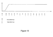
Figure 13 illustrates transmission of absolute and relative buffer status reports in a single service case; -
Figure 14 illustrates transmission of absolute and relative buffer status reports in a multi service case; and -
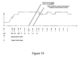
Figure 15 illustrates an error handling operation using both the absolute and relative buffer status reports. -
Figure 1 schematically illustrates a mobile (cellular)telecommunication system 1 in which users of mobile telephones (MT) 3-0, 3-1, and 3-2 can communicate with other users (not shown) via one of the base stations 5-1 or 5-2 and a telephone network 7. A number of uplink and downlink communications resources (sub-carriers, time slots etc) are available for the wireless link between themobile telephones 3 and thebase stations 5. In this embodiment, thebase stations 5 allocate downlink resources to eachmobile telephone 3 depending on the amount of data to be sent to themobile telephone 3. Similarly, thebase stations 5 allocate uplink resources to eachmobile telephone 3 depending on the amount and type of data themobile telephone 3 has to send to thebase station 5. To be able to do this, eachmobile telephone 3 sends regular buffer status reports to itsbase station 5, informing thebase station 5 of the amount and type of data it has in its buffers for transmission. In this embodiment, themobile telephones 3 are arranged to send two types of buffer status reports: - 1. Absolute Buffer Status Reports indicating the amount of data in the mobile telephone's buffer; and
- 2. Relative Buffer Status Reports indicating the change in the amount of data in the mobile telephone's buffer since the last Absolute buffer status report.
- The inventors have found that this arrangement can significantly reduce the signalling overhead needed for QoS aware scheduling.
-
Figure 2 is a block diagram illustrating the main components of each of thebase stations 5 used in this embodiment. As shown, eachbase station 5 includes atransceiver circuit 21 which is operable to transmit signals to and to receive signals from themobile telephones 3 via one ormore antennae 23 and which is operable to transmit signals to and to receive signals from the telephone network 7 via anetwork interface 25. Acontroller 27 controls the operation of thetransceiver circuit 21 in accordance with software stored inmemory 29. The software includes, among other things, anoperating system 31, aresource allocation module 33 and adownlink scheduler 35. Theresource allocation module 33 is operable to allocate the above described communications resources for the uplink and downlink communications to eachmobile telephone 3 and the downlink scheduler schedules the transmission of the downlink data to eachmobile telephone 3 based on the allocated resources. Mobile Telephone -
Figure 3 is a block diagram illustrating the main components of each of themobile telephones 3 shown inFigure 1 . As shown, themobile telephones 3 include atransceiver circuit 71 that is operable to transmit signals to and to receive signals from thebase station 5 via one ormore antennae 73. As shown, themobile telephone 3 also includes acontroller 75 which controls the operation of themobile telephone 3 and which is connected to thetransceiver circuit 71 and to aloudspeaker 77, amicrophone 79, adisplay 81, and akeypad 83. Thecontroller 75 operates in accordance with software instructions stored withinmemory 85. As shown, these software instructions include, among other things, anoperating system 87, anuplink scheduler 89 and a bufferstatus reporting module 90. In this embodiment, the memory also provides anuplink data buffer 91. Theuplink scheduler 89 is responsible for scheduling the transmission of the uplink data from thebuffer 91 in accordance with the resources allocated to themobile telephone 3 for its uplink transmissions by thebase station 5; and the bufferstatus reporting module 90 is responsible for determining and signalling buffer status information to the base station. - In the above description, the
base station 5 and themobile telephones 3 are described for ease of understanding as having discrete resource allocation, scheduling and buffer status reporting modules. Whilst these modules may be provided in this way for certain applications, for example where an existing system has been modified to implement the invention, in other applications, for example in systems designed with the inventive features in mind from the outset, these modules may be built into the overall operating system or code and so these modules may not be discernible as discrete entities. -
Figure 4 illustrates part of a protocol stack (lower three layers) used in themobile telephones 3 and thebase stations 5. The first layer is the physical layer (L1) which is responsible for the actual transmission of the data over the radio communication channel. Above that is the second layer (L2), which is divided into three sub-layers - the Medium Access Control layer (L2/MAC) which is responsible for controlling access to the air interface; the Outer ARQ layer (L2/OARQ) which is responsible for concatenation and segmentation of data packets, the acknowledgment of packets and the re-transmission of data packets where necessary; and the PDCP layer (L2/PDCP) which is responsible for header compression and ciphering. Above the second layer is the Radio Resource Control (RRC) layer (L3/RRC) that is responsible for controlling radio resources used in the air interface between thebase station 5 and themobile telephone 3. As shown, the L2/Outer ARQ layer includes a number ofOuter ARQ entities 95 used to manage the transmission of C-plane data and U-plane data and the L2/PDCP layer includesPDCP entities 97 used to process the C-plane and the U-plane data. -
Figure 4 also shows theradio bearers 98 assigned to each source of data to be transmitted. Several software applications may be operating at the same time and each application may be sending and/or receiving data. The radio bearers are also grouped into groups depending on their data types. For example, the user may be using software on themobile telephone 3 to upload a photograph to a website on the Internet and at the same time, he may be downloading a file from a network server. A respective radio bearer would be associated with each task and in this case, as they both relate to FTP (File Transfer Protocol), the two radio bearers would be in the same radio bearer group. If the user then makes a voice call, then another radio bearer (belonging to another radio bearer group) will be used to control the data transmission and reception for the voice call. Further, as the voice call data is more urgent, it is assigned a higher priority than the FTP data. The communication resources allocated by thebase station 5 for the uplink are shared between theradio bearers 98, depending on their assigned priorities and data rates. TheRRC layer 96 sets the data rate and priority for eachradio bearer 98. Theuplink scheduler 89 then controls the scheduling of the data packets of eachradio bearer 98 for transmission based on the data rates and priorities assigned to the radio bearers by theRRC layer 96. - Typically, the uplink resources required by a
mobile telephone 3 will change over time as the data rate it has to transmit changes. This is illustrated inFigures 5a to 5f for different types of data, where the amount of data is represented by the height of the plot. In particular,Figure 5a illustrates a typical model of data transmissions for HTTP traffic;Figure 5b illustrates a typical model of data transmissions for FTP file download traffic;Figure 5c illustrates a typical model of data transmissions for FTP file upload traffic;Figure 5d illustrates a typical model of data transmissions for multimedia video sharing traffic;Figure 5e illustrates a typical model of data transmissions for multimedia messaging/multiplayer games/push to talk traffic; andFigure 5f illustrates a typical model of data transmissions for VoIP traffic. As shown, some applications like multimedia messaging generate bursty traffic that is unpredictable in nature, whereas others like VoIP are more predictable and allow for semi static allocation of resources through persistent scheduling. However, for TCP based traffic or multimedia video sharing traffic, the bit rates are more steady after the initial starting phase. - In this embodiment, in order to try to optimise the allocation of the uplink resources at any point in time, the base station 5 (and in particular the resource allocation module 33) dynamically adjusts the resources allocated to each
mobile telephone 3 based on their needs. Prior to being transmitted, the uplink data associated with eachradio bearer 98 is buffered in theuplink transmission buffer 91. Therefore, as the data rates change, thebuffer 91 will fill or empty, depending on the difference between the resources needed and the resources currently allocated. Consequently, by signalling the amount of data in thebuffer 91 to thebase station 5, thebase station 5 can dynamically adjust the resources allocated to eachmobile telephone 3. In order that thebase station 5 can allocate the uplink resources taking into account the quality of service (QoS) required for the different types of data being transmitted, the buffer status reports transmitted by themobile telephones 3 include the buffer status for each of the different groups ofradio bearers 98. In this way, thebase station 5 will know, for eachmobile telephone 3 that it is servicing, how much HTTP web browsing traffic thetelephone 3 has to transmit; how much FTP traffic thetelephone 3 has to transmit; how much multimedia video sharing traffic thetelephone 3 has to transmit; how much VoIP traffic thetelephone 3 has to transmit etc. Thebase station 5 can therefore allocate the available uplink resources amongst all themobile telephones 3 based on the priority associated with the data eachmobile telephone 3 has to transmit. - The inventor has appreciated that sending regular buffer status reports, each containing buffer status information for the different radio bearer groups, would require a significant signalling overhead and is unnecessary for a large part of the time as there are sustained periods in which the bit rates remain fairly constant. Therefore, the inventor proposes that the
mobile telephones 3 send two types of buffer status reports - Absolute Buffer.Status Reports and Relative Buffer Status Reports. - These would include the buffer status for each of the Radio Bearer Groups and can be sent during the session start phase when the application has just started and when the bit rate is changing in time before reaching a steady value. Absolute Buffer Status Reports would essentially be event triggered when the amount of data in the mobile telephone's buffer 91 (or alternatively in a traffic flow) gets above (or below) a predefined threshold value.
- These would include only differential buffer status (indicating a change in instantaneous bit rate) with respect to the last sent Absolute Buffer Status Report and can be sent periodically when the applications have reached relatively steady bit rates. Relative Buffer Status Reports will be of small size making it possible to piggyback the buffer status information in a data PDU (Protocol Data Unit) thereby considerably reducing the uplink overhead of sending Absolute Buffer Status Reports periodically for requesting uplink resources. The Relative Buffer Status Reports will include differential buffer status information for each radio bearer group, thereby allowing the
base station 5 to be able to perform QoS aware uplink resource allocations between themobile telephones 3 that it is servicing. -
Figures 6a and 6b illustrate, respectively, an example use of Absolute and Relative Buffer Status Reports for a single service case (file upload) and a multiple service case (file upload + TCP/RLC acknowledgments for web browsing traffic). As shown inFigure 6a , AbsoluteBuffer Status Reports 111 are sent at the start, when the application has just started and when the bit rate changes. Thereafter, RelativeBuffer Status Reports 113 are sent periodically whilst the data rate remains fairly constant. As shown inFigure 6b , because there are two user data sources (one a file upload and the other acknowledgements for received user data packets), the required data rate varies more over the illustrated period and so more AbsoluteBuffer Status Reports 111 are sent. - In this embodiment, the buffer
status reporting module 90 determines whether to send an Absolute or a Relative Buffer Status Report by comparing the amount of data in thebuffer 91 with a stored upper threshold (TU) and a stored lower threshold (TL). If the amount of data in the buffer is above the upper threshold or below the lower threshold, then the bufferstatus reporting module 90 will send an Absolute Buffer Status Report, otherwise it will send a Relative Buffer Status Report. As those skilled in the art will appreciate, in order to be able to calculate a Relative Buffer Status Report from the measured buffer status information, the bufferstatus reporting module 90 has to store the buffer status information transmitted in the last Absolute Buffer Status Report that was sent, and this information is stored in thememory 85. - With regard to the operation of the
base station 5 and in particular theresource allocation module 33, it will have to keep track of the Absolute Buffer Status Reports received from the variousmobile telephones 3 that it is servicing and use them with the received Relative Buffer Status Reports to determine the current buffer status in eachmobile telephone 3, so that it can perform the dynamic resource allocation. - As those skilled in the art will appreciate, there are different ways in which the Relative Buffer Status Reports can encode the required information. For example, they can include a count of the number of bits more or less than the number of bits in the last transmitted Absolute Buffer Status Report or a percentage change (in say increments of 25%) since the last Absolute Buffer Status Report. Relative Buffer Status Reports could also include, for example:
- 1. The number of bytes added or removed from the buffer for each radio bearer group (within predefined thresholds) since the last Absolute Buffer Status Report; or
- 2. The current buffer size as a percentage of size reported in the last ABSR e.g. 0 to 200 percent with 25% increment; or
- 3. The
Base station 5 andmobile telephone 3 could agree a reference buffer size by higher layers, and then the Relative Buffer Status Report can signal the current size as a percentage of this reference; or - It would also be possible to use Relative Buffer Status Reports which indicate the change in buffer status relative to the last Relative Buffer Status Report. However, this is not preferred as if one Relative Buffer Status Report is lost (not received by the base station 5) then an error will propagate through the subsequent reports, until the next Absolute Buffer Status Report. When the relative reports are made relative to the last Absolute Buffer Status Report, lost status reports do not matter as the next Relative Buffer Status report will be correct.
- As those skilled in the art will appreciate, there are also various ways in which the
mobile telephones 3 may decide whether to send an Absolute or a Relative Buffer Status Report. In the above example, the bufferstatus reporting module 90 compared the amount of data in the buffer with upper and lower thresholds. Alternatively, the rate at which data is being written into thebuffer 91 may be compared with upper and lower thresholds. Alternatively still, the difference in the data rate or the difference in the actual amount of data stored in the buffer between a current time point and a previous time point may be compared with a defined value, with the result defining whether to send an Absolute or a Relative Buffer Status Report. - Additionally, as those skilled in the art will appreciate, the buffer status information used to determine whether to send an Absolute or a Relative Buffer Status Report may be different to the buffer status data included in the report. For example, the determination may be made based on the rate at which data is being written into the
buffer 91, whilst the report may contain a count relating to the actual amount of data contained in thebuffer 91 or a count relating to the change in the amount of data in thebuffer 91, depending on if the report is an Absolute or a Relative Buffer Status Report. - As those skilled in the art will appreciate, the operations of the
base station 5 and of themobile telephones 3 may be controlled by dedicated hardware circuits or by programmable controllers controlled by software. The software may be provided at the time of manufacture or subsequently installed after downloading the software from a remote site. - In addition, the Relative Buffer Status Reports could also be utilized as an indication to the
base station 5 to switch from a talk spurt period to a silent period and vise versa for the VoIP service. Based on this indication frommobile telephone 3, thebase station 5 can release persistently allocated uplink resources when switching from a talk spurt period to a silent period or re-allocate uplink resources when switching from a silent period to a talk spurt period. - Various other modifications will be apparent to those skilled in the art and will not be described in further detail here.
- The following is a detailed description of the way in which the present inventions may be implemented in the currently proposed 3GPP LTE standard. Whilst various features are described as being essential or necessary, this may only be the case for the proposed 3GPP LTE standard, for example due to other requirements imposed by the standard. These statements should not, therefore, be construed as limiting the present invention in any way.
- In previous RAN 2 meetings Buffer Reporting for E-UTRAN has been actively discussed with respect to the contents and granularity of buffer reporting. It is now a the general understanding within RAN 2 that more detail buffer status information should be reported to eNB to support QoS-aware scheduling better compared with HSUPA in which only total buffer status and the highest priority logical channel's buffer status are reported to NB. Generally it is agreeable that the buffer status report based a Radio Bearer group would be adopted in LTE in order to have QoS-aware scheduling and at the same time to limit the control signalling overhead as compared to per Radio Bearer Reporting. In this contribution we investigate the uplink traffic model for various applications and suggest optimised reporting to minimise the control signalling overhead.
- A source traffic model essentially consists of two parts: the arrival process for the user activities and the process describing the activity phase. The arrival process determines the instants when a user starts his activity. Such instants are denoted as arrival times. If WWW users are considered, the instant a user begins with his web browsing session is the arrival time for the HTTP application. The modeling approaches for the arrival process are not considered here and are assumed to be identical for the various applications for simplicity.
- The described traffic models are based on a general form of ON/OFF model where a session is generally composed of the some random number of ON/OFF periods described by the appropriate distribution. Each ON period will be further specified in terms of random number of packets, packets durations, packet itert-arrival times, etc.
- The models for the activity phase will be described in the following sections individually for the different services focusing on the uplink traffic patterns. Further, for the TCP based applications, the traffic model assumes the steady maximum bit rate during the activity phase after the slow start. The delay components are illustrated in
Figure 7 . - Web browsing model in its simple form is an ON/OFF model where ON state represents the activity for fetching all objects belonging to one web request after accepting it and the OFF state represents a silence period after all objects in a web request are retrieved. The web traffic is essentially a downlink extensive with steady stream the TCP/ARQ acknowledgements in the uplink during the ON period as shown in
Figure 8 . - The FTP service can be included by describing an FTP file transfer like a web session with only one web request with prolonged active phase. The FTP file transfer is carried out in a manner illustrated in
Figure 9 . - Imaging service such as real time video sharing is about showing to the other end what is going on in your side of the phone connection. Based on initial estimates from video streaming codecs in current networks, a lower bit rate limit is typically around 40 to 64 kbps for a duration varying from tens of seconds to few minutes. For streaming traffic the resources could be persistently allocated, as shown in
Figure 10 , however since the streaming traffic could fluctuate between MBR and GBR, we feel that it might be more efficient to allocate the resources dynamically. - These applications are characterized by short bursts of data at irregular intervals dependent on the user action. The general pattern is shown in
Figure 11 . - VoIP application will generate packets of constant size every 20ms during the talk spurt in a manner illustrated in
Figure 12 . - Multimedia messaging/multiplayer games/Push-to-Talk applications generate traffic burst that is unpredictable in nature and the exact buffer status is needed by the uplink eNB Scheduler to appropriately allocate resources.
- For VoIP the packets are generated every 20ms sec during the talk spurt and the resources would be allocated in the semi static manner through persistent scheduling and therefore dynamic resource allocations for VoIP is not considered further in the paper.
- For TCP based traffic or multimedia video sharing the applications would attain steady bit rate after stating and UE would have to request uplink resources periodically during the activity phase. We believe the uplink signalling overhead reporting buffer status for such can be considerably optimised.
- Based on the traffic patterns for the most common applications being used in the wireless world we could define mechanism for the optimized buffer status reporting mechanism to satisfy the two requirements
- 1. granularity of buffer status reports that is sufficient enough to perform QoS aware scheduling
- 2. minimize the control signalling overhead
- For LTE system, we feel that the buffer status reports based on the radio bearer groups having the same priority would be sufficient to perform QoS aware scheduling. In this scheme UE would include the buffer status of all the Radio Bearer Groups (RBG) in every report and would consequently incur overhead especially if there are many RBG.
- Looking at the traffic patterns of various applications in section 2 we find that there are sustained periods of time (ON period) during which the bit rate for the TCP based applications such as FTP (file upload), SMTP (sending email) and HTTP (TCP/RLC acks) would remain fairly constant after the TCP slow start phase. For multimedia video sharing applications, nearly constant bit rate would also be maintained during the ON periods.
- Considering this, we feel that there would be large overhead if the UE keeps reporting the buffer status of all the Radio Bearer Groups (RBG) in every report especially for the duration when the bit is fairly constant. In order to reduce the uplink overhead we propose that we have two kinds of buffer reports.
- ○ Absolute Buffer Status Reports
- ○ Relative Buffer Status Reports
- Absolute Buffer Status Reports (ABSR): These would include the buffer status of all the Radio Bearer Groups and can be sent during the session start phase where the application has just started and the bit rate is changing in time before reaching a steady value. Absolute Buffer Status Reports would essentially be event triggered when the amount of data in the UE buffer (or alternatively in a traffic flow) gets above (or below) a predefined threshold value.
- Relative Buffer Status Reports (RBSR): These would include only differential buffer status (indicating a change in instantaneous bit rate) with respect to the last sent Absolute Buffer Status report and can be sent periodically when the applications have reached relatively steady bit rates. Relative Buffer Status reports will be of small size making it possible to piggyback the Buffer information in a data PDU thereby considerably reducing the uplink overhead of sending Absolute Buffer Status report periodically for requesting uplink resources.
Relative Buffer Status Reports could include - 1. Number of bytes added or removed form the buffers within a predefined thresholds since the last Absolute Buffer Status Report or
- 2. Current buffer size as a percentage of size reported in the last ABSR e.g. 0 to 200 percent with 25% increment or
- 3. eNB and UE could agree a reference buffer size by higher layers, and then the Relative Buffer Status report can signal the current size as a percentage of this reference
- 4. RBSR could also be utilized as an indication to the eNB to switch from Talk spurt period to silent period and vise versa for the VoIP service. Based on this indication from UE, eNB can release persistently allocated resources when switching form talk spurt period to silent period or re allocated resources when switching from silent to talk spurt period
- The example illustrating the use of absolute and relative buffer status reports in combination for single service and multiple service cases are illustrated in
Figures 13 and14 . - We propose to have Relative Buffer Status Reports additionally to the Absolute Buffer Status Reports to reduce the signalling overhead for buffer status reporting in LTE. UE can smartly switch from Absolute to Relative Buffer Status Report after the application has attained steady bit rate. The use of Absolute to Relative Buffer Status Report for single and multiple service cases are illustrated to demonstrate the decrease in signalling overhead. With such schemes, the signalling overhead can be kept to acceptable limits without loss of granularity of information provided to the uplink eNB scheduler to perform QoS-aware scheduling.
-
- [1] R2-060829, Buffer Reporting for E-UTRAN, Nokia.
- [2] R2-061915, Comparison of UL buffer reporting/scheduling schemes in LTE, Motorola
- We believe that the combination of the Absolute and Relative Buffer Status Report would provide a robust mechanism for uplink eNB scheduler to perform QoS - aware scheduling.
- Since the Relative Buffer Status Report (RBSR) is a differential buffer status (indicating a change in instantaneous bit rate) with respect to the last sent ABSR, even if one of the RBSR is lost, UE in the next scheduled interval shall again report the differential with respect to the last ABSR or send ABSR if the buffer increases predefined threshold. The network will be able to allocate resources appropriately on receiving subsequent RBSR or ABSR after a lost RBSR as shown in
Figure 15 . - Finally, the examples of the present invention will be enumerated below.
- An example 1 describes a method of signalling buffer status information from a mobile communications device to a base station, the method comprising:
- determining current buffer status information for the mobile communications device;
- determining a relationship between the current buffer status information and one or more defined criteria; and
- sending an absolute buffer status report, indicating the current buffer status, or a relative buffer status report, indicating a change in the buffer status since a previous buffer status report, to the base station in dependence upon the determined relationship.
- An example 2 describes the method wherein said buffer status information comprises the amount of data currently held in the buffer.
- An example 3 describes the method wherein said buffer status information comprises the rate at which data is being written into the buffer.
- An example 4 describes the method wherein said absolute buffer status report indicates the total amount of data held within the buffer.
- An example 5 describes the method wherein said absolute buffer status report indicates the rate at which data is being written into the buffer.
- An example 6 describes the method wherein said relative buffer status report indicates the change in the amount of data held within the buffer since said previous buffer status report.
- An example 7 describes the method wherein said relative buffer status report indicates the number of bytes added or removed from the buffer within predefined thresholds since the last absolute buffer status report.
- An example 8 describes the method wherein said relative buffer status report indicates the current buffer size as a percentage of the buffer size reported in the last absolute buffer status report.
- An example 9 describes the method wherein said relative buffer status report indicates the current size of the buffer as a percentage of a predefined reference buffer size.
- An example 10 describes the method wherein said relative buffer status report indicates a change of the rate at which data is being written into the buffer since said previous buffer status report.
- An example 11 describes the method wherein said relative buffer status report indicates a change in the buffer status since the last transmitted absolute buffer status report.
- An example 12 describes the method comprising the step of differencing the current buffer status information and the buffer status information corresponding to the last absolute buffer status report to determine the change in the buffer status since the last transmitted absolute buffer status report.
- An example 13 describes the method wherein said one or more criteria includes upper and lower limits, wherein said determined relationship determines if the current buffer status information falls within said upper and lower limits.
- An example 14 describes the method comprising sending the absolute buffer status report if the current buffer status information falls outside said upper and lower limits and sending the relative buffer status report if the current buffer status information falls within said upper and lower limits.
- An example 15 describes the method wherein said one or more criteria includes a defined change of rate at which data is being written into the buffer, wherein said current buffer status information comprises the change of rate at which data is being written into the buffer since a previous measurement and wherein the relationship is whether the current buffer status information is above or below the defined change of rate.
- An example 16 describes the method wherein the mobile communications device can transmit different types of data and wherein the buffer status reports include buffer status information for each type of data.
- An example 17 describes the method wherein each type of data is associated with a radio bearer group and wherein the buffer status reports include buffer status information for each radio bearer group.
- An example 18 describes the method comprising transmitting data from multiple sources within each radio bearer group.
- An example 19 describes the method comprising indicating in a relative buffer status report that the base station should switch between a talk spurt period and a silent period for a VoIP service.
- An example 20 describes a method of allocating resources to a mobile communications device, comprising:
- storing buffer status information previously received from the mobile communications device, which indicates a previous buffer status within the mobile communications device;
- receiving from the mobile communications device a relative buffer status report indicating a change in the buffer status within the mobile communications device since a previous buffer status report;
- using the stored buffer status information and the relative buffer status report to determine a current buffer status within the mobile communications device; and
- allocating resources to the mobile communications device in dependence upon the determined current buffer status within the mobile communications device.
- An example 21 describes the method wherein said using step uses only a stored absolute buffer status report and the relative buffer status report to determine the current buffer status within the mobile communications device.
- An example 22 describes the method wherein said using step uses a stored absolute buffer status report, the received relative buffer status report and one or more previously received relative buffer status reports to determine the current buffer status within the mobile communications device.
- An example 23 describes the method comprising receiving a new absolute buffer status report from the mobile communications device and updating the stored buffer status information with the new absolute buffer status report.
- An example 24 describes the method comprising receiving buffer status reports from a plurality of mobile communications devices and wherein said allocating step allocates resources to the mobile communications device also in dependence upon the buffer status reports received from at least one other mobile communications device.
- An example 25 describes the method wherein the buffer status reports include buffer status information for different types of data transmitted from the mobile communications device, the data types having different priorities, and wherein said allocating step allocates resources to the mobile communications device in dependence upon the buffer status information received for the different types of data.
- An example 26 describes the method wherein the relative buffer status report includes an indication to switch between a talk spurt and a silent period and wherein, in response to receiving the indication to switch, the method comprises the step of releasing or re-allocating persistently allocated uplink resources to the mobile communications device.
- An example 27 describes a mobile communications device comprising:
- means for determining current buffer status information for the mobile communications device;
- means for determining a relationship between the current buffer status information and one or more defined criteria; and
- means for sending an absolute buffer status report, indicating the current buffer status, or a relative buffer status report, indicating a change in the buffer status since a previous buffer status report, to the base station in dependence upon the determined relationship.
- An example 28 describes the mobile communications device comprising:
- a controller operable under program control to:
- determine current buffer status information for the mobile communications device;
- determine a relationship between the current buffer status information and one or more defined criteria; and
- send an absolute buffer status report, indicating the current buffer status, or a relative buffer status report, indicating a change in the buffer status since a previous buffer status report, to the base station in dependence upon the determined relationship.
- An example 29 describes the mobile communications device operable to perform the method of any of the examples 2 to 19.
- An example 30 describes a base station comprising:
- means for storing buffer status information previously received from the mobile communications device and indicating a previous buffer status within the mobile communications device;
- means for receiving from the mobile communications device a relative buffer status report indicating a change in the buffer status within the mobile communications device since a previous buffer status report;
- means for using the stored buffer status information and the relative buffer status report to determine a current buffer status within the mobile communications device; and
- means for allocating resources to the mobile communications device in dependence upon the determined current buffer status within the mobile communications device.
- An example 31 describes a base station comprising:
- a controller operable under program control to:
- store buffer status information relating to a previous buffer status within the mobile communications device;
- receive from the mobile communications device a relative buffer status report indicating a change in the buffer status within the mobile communications device since a previous buffer status report;
- use the stored buffer status information and the relative buffer status report to determine a current buffer status within the mobile communications device; and
- allocate resources to the mobile communications device in dependence upon the determined current buffer status within the mobile communications device.
- An example 32 describes the base station operable to perform the method of any of the examples 21 to 26.
- An example 33 describes a computer implementable instructions product comprising computer implementable instructions for causing a computer device to perform the method of any of the examples 1 to 26.
- An example 34 describes a method of signalling buffer status information from a mobile communications device to a base station, the method comprising,
determining current buffer status information for the mobile communications device;
determining a relationship between the current buffer status information and one or more defined criteria;
sending a buffer status report indicating the current buffer status to the base station in dependence upon the determined relationship; and
indicating in the buffer status report that the base station should switch between a talk spurt period and a silent period for a VoIP service. - An example 35 describes a method of signalling buffer status information from a mobile communications device to a base station, the method comprising:
- transmitting different types of data from the communications device to the base station, each type of data being associated with a respective radio bearer group;
- buffering data to be transmitted in a transmit buffer;
- determining buffer status information for data buffered in the transmit buffer for each radio bearer group;
- sending a buffer status report indicating the current buffer status for each radio bearer group to the base station in dependence upon the determined buffer status information; and
- including an indication in the buffer status report that the base station should switch between a talk spurt period and a silent period for a VoIP service.
- An example 36 describes a method of allocating resources to a mobile communications device comprising:
- receiving data from a mobile communications device;
- receiving a buffer status report from the mobile communications device indicating that the base station should switch between a talk spurt period and a silent period for a VoIP service; and
- releasing or re-allocating persistently allocated uplink resources to the mobile communications device in dependence upon the received indication.
- An example 37 describes a method of allocating resources to a mobile communications device comprising:
- receiving different types of data from a mobile communications device;
- receiving a buffer status report from the mobile communications device having buffer status information for each type of data and an indication that the base station should switch between a talk spurt period and a silent period for a VoIP service; and
- releasing or re-allocating persistently allocated uplink resources to the mobile communications device in dependence upon the received indication.
Claims (22)
- A method or signalling buffer status information from a mobile communications device (3) to a base station (5), the method comprising:determining current buffer status information for the mobile communications device (3);determining a relationship between the current buffer status information and one or more defined criteria; andsending an absolute buffer status report, indicating the current buffer status, or a relative buffer status report, indicating a change in the buffer status since a previous buffer status report, to the base station (5) in dependence upon the determined relationship.
- A method according to claim 1, wherein said buffer status information comprises the amount of data currently held in the buffer.
- A method according to claim 1, wherein said buffer status information comprises the rate at which data is being written into the buffer.
- A method according to any preceding claim, wherein said absolute buffer status report indicates the total amount of data held within the buffer.
- A method according to any of claims 1 to 3, wherein said absolute buffer status report indicates the rate at which data is being written into the buffer.
- A method according to any preceding claim, wherein said relative buffer status report indicates the change in the amount of data held within the buffer since said previous buffer status report.
- A method according to any of claims 1 to 5, wherein said relative buffer status report indicates the number of bytes added or removed from the buffer within predefined thresholds since the last absolute buffer status report.
- A method according to any of claims 1 to 5, wherein said relative buffer status report indicates the current buffer size as a percentage of the buffer size reported in the last absolute buffer status report.
- A method according to any of claims 1 to 5, wherein said relative buffer status report indicates the current size of the buffer as a percentage of a predefined reference buffer size.
- A method according to any of claims 1 to 5, wherein said relative buffer status report indicates a change of the rate at which data is being written into the buffer since said previous buffer status report.
- A method according to any preceding claim, wherein said relative buffer status report indicates a change in the buffer status since the last transmitted absolute buffer status report.
- A method according to claim 11, comprising the step of differencing the current buffer status information and the buffer status information corresponding to the last absolute buffer status report to determine the change in the buffer status since the last transmitted absolute buffer status report.
- A method according to any preceding claim, wherein said one or more criteria includes upper and lower limits, wherein said determined relationship determines if the current buffer status information falls within said upper and lower limits.
- A method according to claim 13, comprising sending the absolute buffer status report if the current buffer status information falls outside said upper and lower limits and sending the relative buffer status report if the current buffer status information falls within said upper and lower limits.
- A method according to any preceding claim, wherein said one or more criteria includes a defined change of rate at which data is being written into the buffer, wherein said current buffer status information comprises the change of rate at which data is being written into the buffer since a previous measurement and wherein the relationship is whether the current buffer status information is above or below the defined change of rate.
- A method according to any preceding claim, wherein the mobile communications device can transmit different types of data and wherein the buffer status reports include buffer status information for each type of data.
- A method according to claim 16, wherein each type of data is associated with a radio bearer group and wherein the buffer status reports include buffer status information for each radio bearer group.
- A method according to claim 17, comprising transmitting data from multiple sources within each radio bearer group.
- A method according to any preceding claim, comprising indicating in a relative buffer status report that the base station should switch between a talk spurt period and a silent period for a VoIP service.
- A mobile communications device (3) comprising:means for determining current buffer status information for the mobile communications device (3);means for determining a relationship between the current buffer status information and one or more defined criteria; andmeans for sending an absolute buffer status report, indicating the current buffer status, or a relative buffer status report, indicating a change in the buffer status since a previous buffer status report, to the base station in dependence upon the determined relationship.
- A mobile communications device according to claim 20 further comprising means operable to perform the steps of the method of any of claims 2 to 19.
- A computer program product comprising computer implementable instructions for causing a computer device to perform the method of any of claims 1 to 19, when said instructions are running on said computer device.
Applications Claiming Priority (2)
| Application Number | Priority Date | Filing Date | Title |
|---|---|---|---|
| GB0711884A GB2452013A (en) | 2007-06-19 | 2007-06-19 | Buffer status reporting from a mobile communications device |
| PCT/JP2008/061505 WO2008156198A2 (en) | 2007-06-19 | 2008-06-18 | Buffer status reporting |
Publications (2)
| Publication Number | Publication Date |
|---|---|
| EP2165558A2 EP2165558A2 (en) | 2010-03-24 |
| EP2165558B1 true EP2165558B1 (en) | 2011-11-23 |
Family
ID=38332402
Family Applications (1)
| Application Number | Title | Priority Date | Filing Date |
|---|---|---|---|
| EP08765826A Active EP2165558B1 (en) | 2007-06-19 | 2008-06-18 | Buffer status reporting |
Country Status (8)
| Country | Link |
|---|---|
| US (1) | US7953064B2 (en) |
| EP (1) | EP2165558B1 (en) |
| JP (2) | JP2010529727A (en) |
| KR (1) | KR101126802B1 (en) |
| CN (2) | CN102791037B (en) |
| AT (1) | ATE535122T1 (en) |
| GB (1) | GB2452013A (en) |
| WO (1) | WO2008156198A2 (en) |
Families Citing this family (52)
| Publication number | Priority date | Publication date | Assignee | Title |
|---|---|---|---|---|
| CN101572913A (en) * | 2008-04-28 | 2009-11-04 | 华为技术有限公司 | Processing method and device for status report of buffer area |
| US8639997B2 (en) * | 2008-09-03 | 2014-01-28 | Qualcomm Incorporated | Buffer status report triggers in wireless communications |
| US8873474B2 (en) * | 2008-10-17 | 2014-10-28 | Telefonaktiebolaget L M Ericsson (Publ) | Method and mobile terminal providing priority-based uplink scheduling information |
| WO2010087617A2 (en) | 2009-01-29 | 2010-08-05 | Samsung Electronics Co., Ltd. | Method and system for computing and sending resource requests and avoiding deadlock situations in mobile communication system |
| US9137160B2 (en) * | 2009-01-29 | 2015-09-15 | Qualcomm Incorporated | Method and apparatus for accomodating a receiver buffer to prevent data overflow |
| CN102308654B (en) * | 2009-02-09 | 2014-11-26 | 瑞典爱立信有限公司 | Method and arrangement in a wireless communication system |
| US9572193B2 (en) * | 2009-03-12 | 2017-02-14 | Nokia Solutions And Networks Oy | Device-to-device communication |
| EP2237633A1 (en) | 2009-04-03 | 2010-10-06 | Panasonic Corporation | Buffer status reporting in a mobile communication system |
| BRPI1006380B1 (en) * | 2009-04-16 | 2021-04-06 | Koninklijke Philips N.V. | METHOD FOR COMMUNICATION IN A NETWORK FROM A FIRST STATION TO A SECOND STATION AND RADIO STATION |
| US20100271990A1 (en) * | 2009-04-24 | 2010-10-28 | Motorola, Inc. | Method and apparatus for triggering buffer status reports with packet discarding |
| ES2568219T3 (en) * | 2009-05-05 | 2016-04-28 | Telefonaktiebolaget Lm Ericsson (Publ) | Manipulation of a planning request trigger |
| US8576714B2 (en) * | 2009-05-29 | 2013-11-05 | Futurewei Technologies, Inc. | System and method for relay node flow control in a wireless communications system |
| KR101632739B1 (en) * | 2009-06-18 | 2016-06-22 | 한국전자통신연구원 | Data Transmission Method In Communication Systems and Relay Performing the Method |
| JP5372171B2 (en) * | 2009-10-13 | 2013-12-18 | 三菱電機株式会社 | In-vehicle wireless communication device and in-vehicle wireless communication system |
| KR101331048B1 (en) * | 2009-12-16 | 2013-11-19 | 한국전자통신연구원 | Buffer status reporting method for uplink scheduling and communication system using the same |
| JP5338747B2 (en) * | 2010-05-12 | 2013-11-13 | 富士通株式会社 | Mobile radio communication system including uplink radio resource allocation function |
| US8918563B2 (en) * | 2010-06-01 | 2014-12-23 | Qualcomm Incorporated | Uplink data throttling by buffer status report (BSR) scaling |
| CN105491618B (en) * | 2010-06-18 | 2019-05-14 | 富士通株式会社 | Terminal, base station and communication system |
| MX2012014660A (en) | 2010-06-18 | 2013-01-22 | Fujitsu Ltd | Reporting method of terminal buffer state report(bsr), obtaining method for obtaining bsr from base station, and corresponding terminal, base station, communication system. |
| US8693355B2 (en) * | 2010-06-21 | 2014-04-08 | Motorola Solutions, Inc. | Jitter buffer management for power savings in a wireless communication device |
| JP5575984B2 (en) * | 2010-06-22 | 2014-08-20 | ゼットティーイー コーポレイション | Method and system for reporting buffer size index |
| US9160662B2 (en) * | 2010-08-20 | 2015-10-13 | Google Technology Holdings LLC | Uplink buffer status reporting of relay stations in wireless networks |
| CN102083206B (en) * | 2011-01-24 | 2013-04-17 | 华为技术有限公司 | Method, device and system for allocating air interface resources |
| KR101772122B1 (en) | 2011-03-18 | 2017-08-28 | 삼성전자 주식회사 | Method and appratus for sending buffer status report in wireless communication system |
| CN102781096B (en) * | 2011-05-09 | 2015-05-27 | 华为技术有限公司 | Method and user equipment for resource scheduling |
| US9019851B2 (en) | 2011-06-21 | 2015-04-28 | Telefonaktiebolaget L M Ericsson (Publ) | Network node and method related to buffer estimation |
| US9019880B2 (en) | 2011-08-11 | 2015-04-28 | Qualcomm Incorporated | Methods and apparatus for overload mitigation using uplink transmit power backoff |
| US9288733B2 (en) * | 2011-09-23 | 2016-03-15 | Telefonaktiebolaget L M Ericsson (Publ) | Systems and methods for controlling cell selection in a heterogeneous cellular network based on primary direction of traffic flow |
| JP2013098641A (en) * | 2011-10-28 | 2013-05-20 | Kddi Corp | Radio resource allocation apparatus, base station, and radio resource allocation method |
| US9253794B2 (en) | 2011-12-02 | 2016-02-02 | Telefonaktiebolaget L M Ericsson (Publ) | Efficient spectrum utilization with almost blank subframes |
| CN104365145B (en) * | 2012-04-20 | 2018-10-23 | 瑞典爱立信有限公司 | Consider that the switching for video or other streaming services for playing cache size determines |
| CN102740281B (en) * | 2012-06-20 | 2015-12-16 | 华为技术有限公司 | Data transmission method for uplink, communication equipment and communication system |
| US8948006B2 (en) | 2013-01-07 | 2015-02-03 | Freescale Semiconductor, Inc. | System for managing uplink quality of service (QoS) in cellular network |
| US9071984B1 (en) * | 2013-02-15 | 2015-06-30 | Sprint Spectrum L.P. | Modifying a data flow mechanism variable in a communication network |
| WO2014145845A1 (en) | 2013-03-15 | 2014-09-18 | Huawei Technologies Co., Ltd. | System and method for buffer status reporting for multi-stream aggregation |
| US9497682B2 (en) | 2013-06-07 | 2016-11-15 | Intel Corporation | Central processing unit and methods for supporting coordinated multipoint transmission in an LTE network |
| WO2015055238A1 (en) * | 2013-10-16 | 2015-04-23 | Telefonaktiebolaget L M Ericsson (Publ) | Method and apparatus in a wireless communication system |
| KR102350504B1 (en) * | 2015-04-27 | 2022-01-14 | 삼성전자주식회사 | Apparatus and method for controlling downlink throughput in communication system |
| KR102363476B1 (en) * | 2015-05-15 | 2022-02-16 | 주식회사 윌러스표준기술연구소 | Wireless communication method and wireless communication terminal for transmitting information on buffer status |
| CN105142220B (en) * | 2015-06-30 | 2018-05-22 | 大唐移动通信设备有限公司 | A kind of dynamic deferred dispatching method of voice data and base station |
| WO2017098588A1 (en) * | 2015-12-08 | 2017-06-15 | 富士通株式会社 | Wireless communication system, base station, terminal, and scheduling method |
| US10028168B2 (en) * | 2015-12-08 | 2018-07-17 | Huawei Technologies Co., Ltd. | Method and apparatus for remote buffer status maintenance |
| JP6775163B2 (en) * | 2015-12-11 | 2020-10-28 | パナソニックIpマネジメント株式会社 | Wireless base stations, wireless terminals, wireless communication systems and audio signal communication methods |
| US20170212865A1 (en) * | 2016-01-26 | 2017-07-27 | Qualcomm Incorporated | Methods and apparatus for improving buffer size setting for one or more buffer status reports |
| WO2017132995A1 (en) | 2016-02-05 | 2017-08-10 | 广东欧珀移动通信有限公司 | Service transmission method and device |
| US11190972B2 (en) * | 2016-02-18 | 2021-11-30 | Lg Electronics Inc. | Method for performing uplink transmission in wireless LAN system and terminal using same |
| US10966116B2 (en) * | 2016-03-31 | 2021-03-30 | Ntt Docomo, Inc. | User equipment |
| US20170332385A1 (en) * | 2016-05-11 | 2017-11-16 | Qualcomm Incorporated | Buffer status reporting in a wireless local area network (wlan) |
| CN107404732B (en) * | 2016-05-18 | 2020-01-24 | 普天信息技术有限公司 | Method and device for reporting cache report |
| US11483853B2 (en) * | 2019-08-01 | 2022-10-25 | Qualcomm Incorporated | Techniques for buffering a file |
| US11134020B1 (en) * | 2020-04-16 | 2021-09-28 | Morgan Stanley Services Group Inc. | Flow control of two TCP streams between three network nodes |
| US20230362714A1 (en) * | 2020-07-01 | 2023-11-09 | Telefonaktiebolaget Lm Ericsson (Publ) | Sending and Receiving a PDU |
Family Cites Families (13)
| Publication number | Priority date | Publication date | Assignee | Title |
|---|---|---|---|---|
| GB0101115D0 (en) * | 2001-01-16 | 2001-02-28 | Siemens Ag | Improvements in or relating to radio communications network |
| US6917587B1 (en) * | 2001-02-01 | 2005-07-12 | Cisco Technology, Inc. | Method and apparatus for recovering a call resource from a call session |
| CN101715194A (en) * | 2002-10-18 | 2010-05-26 | 卡耐特无线有限公司 | Apparatus and method for extending the coverage area of a licensed wireless communication system using an unlicensed wireless communication system |
| US20050078651A1 (en) * | 2003-08-16 | 2005-04-14 | Samsung Electronics Co., Ltd. | Method and apparatus for assigning scheduling for uplink packet transmission in a mobile communication system |
| EP1679933B1 (en) * | 2003-09-30 | 2009-07-01 | Mitsubishi Denki K.K. | Mobile communication system for controlling communication mode |
| JP4647655B2 (en) * | 2004-05-06 | 2011-03-09 | サムスン エレクトロニクス カンパニー リミテッド | Apparatus and method for transmitting / receiving transmission state information and buffer state information in mobile communication system supporting uplink packet service |
| EP1617606A1 (en) * | 2004-07-16 | 2006-01-18 | Matsushita Electric Industrial Co., Ltd. | Scheduling mode switching for uplink transmissions |
| GB2418105A (en) * | 2004-09-13 | 2006-03-15 | Fujitsu Ltd | Relative indicators used for scheduling of uplink transmissions |
| KR101141649B1 (en) * | 2004-11-09 | 2012-05-17 | 엘지전자 주식회사 | method of transmitting and receiving control information for enhanced uplink data channel |
| EP2071769A4 (en) * | 2006-08-22 | 2013-04-03 | Ntt Docomo Inc | Radio resource opening/controlling method, radio base station and mobile station |
| TW200824474A (en) * | 2006-10-28 | 2008-06-01 | Interdigital Tech Corp | Method and apparatus for scheduling uplink transmissions for real time services during a silent period |
| KR101498026B1 (en) * | 2007-05-08 | 2015-03-04 | 엘지전자 주식회사 | Methods of transmitting and receiving data in mobile communication system and device supporting the same |
| US20080311921A1 (en) * | 2007-06-18 | 2008-12-18 | Infineon Technologies Ag | Communication resource signaling |
-
2007
- 2007-06-19 GB GB0711884A patent/GB2452013A/en not_active Withdrawn
-
2008
- 2008-06-18 JP JP2010509992A patent/JP2010529727A/en active Pending
- 2008-06-18 CN CN201210195281.1A patent/CN102791037B/en active Active
- 2008-06-18 CN CN2008800210286A patent/CN101682922B/en active Active
- 2008-06-18 EP EP08765826A patent/EP2165558B1/en active Active
- 2008-06-18 KR KR1020107001107A patent/KR101126802B1/en active IP Right Grant
- 2008-06-18 AT AT08765826T patent/ATE535122T1/en active
- 2008-06-18 US US12/452,122 patent/US7953064B2/en active Active
- 2008-06-18 WO PCT/JP2008/061505 patent/WO2008156198A2/en active Application Filing
-
2012
- 2012-02-23 JP JP2012037408A patent/JP5207011B2/en active Active
Also Published As
| Publication number | Publication date |
|---|---|
| EP2165558A2 (en) | 2010-03-24 |
| CN101682922B (en) | 2013-06-19 |
| WO2008156198A2 (en) | 2008-12-24 |
| US7953064B2 (en) | 2011-05-31 |
| GB2452013A (en) | 2009-02-25 |
| CN102791037B (en) | 2015-08-05 |
| WO2008156198A3 (en) | 2009-04-09 |
| US20100135166A1 (en) | 2010-06-03 |
| JP5207011B2 (en) | 2013-06-12 |
| CN102791037A (en) | 2012-11-21 |
| GB0711884D0 (en) | 2007-07-25 |
| KR101126802B1 (en) | 2012-03-23 |
| KR20100023034A (en) | 2010-03-03 |
| JP2010529727A (en) | 2010-08-26 |
| CN101682922A (en) | 2010-03-24 |
| JP2012110047A (en) | 2012-06-07 |
| ATE535122T1 (en) | 2011-12-15 |
Similar Documents
| Publication | Publication Date | Title |
|---|---|---|
| EP2165558B1 (en) | Buffer status reporting | |
| CN102369778B (en) | Buffer status reporting in a mobile communication system | |
| US9398524B2 (en) | Method and apparatus for supporting uplink starvation avoidance in a long term evolution system | |
| EP2041928B1 (en) | Compressed delay packet transmission scheduling | |
| JP4903861B2 (en) | Method and apparatus for efficiently transmitting schedule information in a wireless communication system | |
| US8385931B2 (en) | Methods and arrangements for allocating scheduling request resources in a wireless communication system | |
| EP2181532B1 (en) | Scheduling in wireless networks | |
| KR100879613B1 (en) | Method and apparatus for non-schedule transmission of packet service in mobile telecommunication system | |
| EP2058990B1 (en) | Apparatus and method for transmitting and receiving control information for uplink data in a mobile communication system | |
| IL200892A (en) | Method and apparatus for supporting uplink starvation avoidance in a long term evolution system | |
| CN102239666A (en) | Method and device for enabling indication of congestion in a telecommunications network | |
| JP2012524443A (en) | Method for communicating in a network | |
| CN102946622A (en) | Method and device for establishing business flow as well as business flow revising method and device | |
| US8130713B2 (en) | System and method for credit-based channel transmission scheduling (CBCTS) | |
| CN111510953B (en) | Data processing method, terminal and storage medium | |
| KR20080015704A (en) | Method and apparatus for sending state transition indication in mobile communication system supported voice over internet protocol |
Legal Events
| Date | Code | Title | Description |
|---|---|---|---|
| PUAI | Public reference made under article 153(3) epc to a published international application that has entered the european phase |
Free format text: ORIGINAL CODE: 0009012 |
|
| 17P | Request for examination filed |
Effective date: 20091217 |
|
| AK | Designated contracting states |
Kind code of ref document: A2 Designated state(s): AT BE BG CH CY CZ DE DK EE ES FI FR GB GR HR HU IE IS IT LI LT LU LV MC MT NL NO PL PT RO SE SI SK TR |
|
| AX | Request for extension of the european patent |
Extension state: AL BA MK RS |
|
| RIC1 | Information provided on ipc code assigned before grant |
Ipc: H04W 4/00 20090101AFI20100223BHEP |
|
| RIC1 | Information provided on ipc code assigned before grant |
Ipc: H04W 72/12 20090101AFI20101221BHEP |
|
| GRAP | Despatch of communication of intention to grant a patent |
Free format text: ORIGINAL CODE: EPIDOSNIGR1 |
|
| DAX | Request for extension of the european patent (deleted) | ||
| GRAS | Grant fee paid |
Free format text: ORIGINAL CODE: EPIDOSNIGR3 |
|
| GRAA | (expected) grant |
Free format text: ORIGINAL CODE: 0009210 |
|
| AK | Designated contracting states |
Kind code of ref document: B1 Designated state(s): AT BE BG CH CY CZ DE DK EE ES FI FR GB GR HR HU IE IS IT LI LT LU LV MC MT NL NO PL PT RO SE SI SK TR |
|
| REG | Reference to a national code |
Ref country code: GB Ref legal event code: FG4D |
|
| REG | Reference to a national code |
Ref country code: CH Ref legal event code: EP |
|
| REG | Reference to a national code |
Ref country code: IE Ref legal event code: FG4D |
|
| REG | Reference to a national code |
Ref country code: DE Ref legal event code: R096 Ref document number: 602008011577 Country of ref document: DE Effective date: 20120209 |
|
| REG | Reference to a national code |
Ref country code: NL Ref legal event code: VDEP Effective date: 20111123 |
|
| LTIE | Lt: invalidation of european patent or patent extension |
Effective date: 20111123 |
|
| PG25 | Lapsed in a contracting state [announced via postgrant information from national office to epo] |
Ref country code: IS Free format text: LAPSE BECAUSE OF FAILURE TO SUBMIT A TRANSLATION OF THE DESCRIPTION OR TO PAY THE FEE WITHIN THE PRESCRIBED TIME-LIMIT Effective date: 20120323 Ref country code: NO Free format text: LAPSE BECAUSE OF FAILURE TO SUBMIT A TRANSLATION OF THE DESCRIPTION OR TO PAY THE FEE WITHIN THE PRESCRIBED TIME-LIMIT Effective date: 20120223 Ref country code: LT Free format text: LAPSE BECAUSE OF FAILURE TO SUBMIT A TRANSLATION OF THE DESCRIPTION OR TO PAY THE FEE WITHIN THE PRESCRIBED TIME-LIMIT Effective date: 20111123 |
|
| PG25 | Lapsed in a contracting state [announced via postgrant information from national office to epo] |
Ref country code: HR Free format text: LAPSE BECAUSE OF FAILURE TO SUBMIT A TRANSLATION OF THE DESCRIPTION OR TO PAY THE FEE WITHIN THE PRESCRIBED TIME-LIMIT Effective date: 20111123 Ref country code: LV Free format text: LAPSE BECAUSE OF FAILURE TO SUBMIT A TRANSLATION OF THE DESCRIPTION OR TO PAY THE FEE WITHIN THE PRESCRIBED TIME-LIMIT Effective date: 20111123 Ref country code: SE Free format text: LAPSE BECAUSE OF FAILURE TO SUBMIT A TRANSLATION OF THE DESCRIPTION OR TO PAY THE FEE WITHIN THE PRESCRIBED TIME-LIMIT Effective date: 20111123 Ref country code: NL Free format text: LAPSE BECAUSE OF FAILURE TO SUBMIT A TRANSLATION OF THE DESCRIPTION OR TO PAY THE FEE WITHIN THE PRESCRIBED TIME-LIMIT Effective date: 20111123 Ref country code: GR Free format text: LAPSE BECAUSE OF FAILURE TO SUBMIT A TRANSLATION OF THE DESCRIPTION OR TO PAY THE FEE WITHIN THE PRESCRIBED TIME-LIMIT Effective date: 20120224 Ref country code: PT Free format text: LAPSE BECAUSE OF FAILURE TO SUBMIT A TRANSLATION OF THE DESCRIPTION OR TO PAY THE FEE WITHIN THE PRESCRIBED TIME-LIMIT Effective date: 20120323 Ref country code: SI Free format text: LAPSE BECAUSE OF FAILURE TO SUBMIT A TRANSLATION OF THE DESCRIPTION OR TO PAY THE FEE WITHIN THE PRESCRIBED TIME-LIMIT Effective date: 20111123 Ref country code: BE Free format text: LAPSE BECAUSE OF FAILURE TO SUBMIT A TRANSLATION OF THE DESCRIPTION OR TO PAY THE FEE WITHIN THE PRESCRIBED TIME-LIMIT Effective date: 20111123 |
|
| PG25 | Lapsed in a contracting state [announced via postgrant information from national office to epo] |
Ref country code: CY Free format text: LAPSE BECAUSE OF FAILURE TO SUBMIT A TRANSLATION OF THE DESCRIPTION OR TO PAY THE FEE WITHIN THE PRESCRIBED TIME-LIMIT Effective date: 20111123 |
|
| PG25 | Lapsed in a contracting state [announced via postgrant information from national office to epo] |
Ref country code: CZ Free format text: LAPSE BECAUSE OF FAILURE TO SUBMIT A TRANSLATION OF THE DESCRIPTION OR TO PAY THE FEE WITHIN THE PRESCRIBED TIME-LIMIT Effective date: 20111123 Ref country code: SK Free format text: LAPSE BECAUSE OF FAILURE TO SUBMIT A TRANSLATION OF THE DESCRIPTION OR TO PAY THE FEE WITHIN THE PRESCRIBED TIME-LIMIT Effective date: 20111123 Ref country code: BG Free format text: LAPSE BECAUSE OF FAILURE TO SUBMIT A TRANSLATION OF THE DESCRIPTION OR TO PAY THE FEE WITHIN THE PRESCRIBED TIME-LIMIT Effective date: 20120223 Ref country code: EE Free format text: LAPSE BECAUSE OF FAILURE TO SUBMIT A TRANSLATION OF THE DESCRIPTION OR TO PAY THE FEE WITHIN THE PRESCRIBED TIME-LIMIT Effective date: 20111123 Ref country code: DK Free format text: LAPSE BECAUSE OF FAILURE TO SUBMIT A TRANSLATION OF THE DESCRIPTION OR TO PAY THE FEE WITHIN THE PRESCRIBED TIME-LIMIT Effective date: 20111123 |
|
| PG25 | Lapsed in a contracting state [announced via postgrant information from national office to epo] |
Ref country code: RO Free format text: LAPSE BECAUSE OF FAILURE TO SUBMIT A TRANSLATION OF THE DESCRIPTION OR TO PAY THE FEE WITHIN THE PRESCRIBED TIME-LIMIT Effective date: 20111123 Ref country code: PL Free format text: LAPSE BECAUSE OF FAILURE TO SUBMIT A TRANSLATION OF THE DESCRIPTION OR TO PAY THE FEE WITHIN THE PRESCRIBED TIME-LIMIT Effective date: 20111123 Ref country code: IT Free format text: LAPSE BECAUSE OF FAILURE TO SUBMIT A TRANSLATION OF THE DESCRIPTION OR TO PAY THE FEE WITHIN THE PRESCRIBED TIME-LIMIT Effective date: 20111123 |
|
| REG | Reference to a national code |
Ref country code: AT Ref legal event code: MK05 Ref document number: 535122 Country of ref document: AT Kind code of ref document: T Effective date: 20111123 |
|
| PLBE | No opposition filed within time limit |
Free format text: ORIGINAL CODE: 0009261 |
|
| STAA | Information on the status of an ep patent application or granted ep patent |
Free format text: STATUS: NO OPPOSITION FILED WITHIN TIME LIMIT |
|
| 26N | No opposition filed |
Effective date: 20120824 |
|
| REG | Reference to a national code |
Ref country code: DE Ref legal event code: R097 Ref document number: 602008011577 Country of ref document: DE Effective date: 20120824 |
|
| PG25 | Lapsed in a contracting state [announced via postgrant information from national office to epo] |
Ref country code: AT Free format text: LAPSE BECAUSE OF FAILURE TO SUBMIT A TRANSLATION OF THE DESCRIPTION OR TO PAY THE FEE WITHIN THE PRESCRIBED TIME-LIMIT Effective date: 20111123 Ref country code: MC Free format text: LAPSE BECAUSE OF NON-PAYMENT OF DUE FEES Effective date: 20120630 |
|
| REG | Reference to a national code |
Ref country code: CH Ref legal event code: PL |
|
| REG | Reference to a national code |
Ref country code: CH Ref legal event code: PL |
|
| REG | Reference to a national code |
Ref country code: IE Ref legal event code: MM4A |
|
| PG25 | Lapsed in a contracting state [announced via postgrant information from national office to epo] |
Ref country code: CH Free format text: LAPSE BECAUSE OF NON-PAYMENT OF DUE FEES Effective date: 20120630 Ref country code: LI Free format text: LAPSE BECAUSE OF NON-PAYMENT OF DUE FEES Effective date: 20120630 Ref country code: ES Free format text: LAPSE BECAUSE OF FAILURE TO SUBMIT A TRANSLATION OF THE DESCRIPTION OR TO PAY THE FEE WITHIN THE PRESCRIBED TIME-LIMIT Effective date: 20120305 Ref country code: IE Free format text: LAPSE BECAUSE OF NON-PAYMENT OF DUE FEES Effective date: 20120618 |
|
| PG25 | Lapsed in a contracting state [announced via postgrant information from national office to epo] |
Ref country code: FI Free format text: LAPSE BECAUSE OF FAILURE TO SUBMIT A TRANSLATION OF THE DESCRIPTION OR TO PAY THE FEE WITHIN THE PRESCRIBED TIME-LIMIT Effective date: 20111123 |
|
| PG25 | Lapsed in a contracting state [announced via postgrant information from national office to epo] |
Ref country code: MT Free format text: LAPSE BECAUSE OF FAILURE TO SUBMIT A TRANSLATION OF THE DESCRIPTION OR TO PAY THE FEE WITHIN THE PRESCRIBED TIME-LIMIT Effective date: 20111123 |
|
| PG25 | Lapsed in a contracting state [announced via postgrant information from national office to epo] |
Ref country code: TR Free format text: LAPSE BECAUSE OF FAILURE TO SUBMIT A TRANSLATION OF THE DESCRIPTION OR TO PAY THE FEE WITHIN THE PRESCRIBED TIME-LIMIT Effective date: 20111123 |
|
| PG25 | Lapsed in a contracting state [announced via postgrant information from national office to epo] |
Ref country code: LU Free format text: LAPSE BECAUSE OF NON-PAYMENT OF DUE FEES Effective date: 20120618 |
|
| PG25 | Lapsed in a contracting state [announced via postgrant information from national office to epo] |
Ref country code: HU Free format text: LAPSE BECAUSE OF FAILURE TO SUBMIT A TRANSLATION OF THE DESCRIPTION OR TO PAY THE FEE WITHIN THE PRESCRIBED TIME-LIMIT Effective date: 20080618 |
|
| REG | Reference to a national code |
Ref country code: FR Ref legal event code: PLFP Year of fee payment: 9 |
|
| REG | Reference to a national code |
Ref country code: FR Ref legal event code: PLFP Year of fee payment: 10 |
|
| REG | Reference to a national code |
Ref country code: FR Ref legal event code: PLFP Year of fee payment: 11 |
|
| PGFP | Annual fee paid to national office [announced via postgrant information from national office to epo] |
Ref country code: FR Payment date: 20230627 Year of fee payment: 16 Ref country code: DE Payment date: 20230620 Year of fee payment: 16 |
|
| PGFP | Annual fee paid to national office [announced via postgrant information from national office to epo] |
Ref country code: GB Payment date: 20230620 Year of fee payment: 16 |