EP2164284A2 - Molded pull string for custom hearing instruments - Google Patents
Molded pull string for custom hearing instruments Download PDFInfo
- Publication number
- EP2164284A2 EP2164284A2 EP09167626A EP09167626A EP2164284A2 EP 2164284 A2 EP2164284 A2 EP 2164284A2 EP 09167626 A EP09167626 A EP 09167626A EP 09167626 A EP09167626 A EP 09167626A EP 2164284 A2 EP2164284 A2 EP 2164284A2
- Authority
- EP
- European Patent Office
- Prior art keywords
- shell
- pull string
- anchor
- set forth
- hearing instrument
- Prior art date
- Legal status (The legal status is an assumption and is not a legal conclusion. Google has not performed a legal analysis and makes no representation as to the accuracy of the status listed.)
- Withdrawn
Links
Images



Classifications
-
- H—ELECTRICITY
- H04—ELECTRIC COMMUNICATION TECHNIQUE
- H04R—LOUDSPEAKERS, MICROPHONES, GRAMOPHONE PICK-UPS OR LIKE ACOUSTIC ELECTROMECHANICAL TRANSDUCERS; ELECTRIC HEARING AIDS; PUBLIC ADDRESS SYSTEMS
- H04R25/00—Electric hearing aids
- H04R25/60—Mounting or interconnection of hearing aid parts, e.g. inside tips, housings or to ossicles
-
- H—ELECTRICITY
- H04—ELECTRIC COMMUNICATION TECHNIQUE
- H04R—LOUDSPEAKERS, MICROPHONES, GRAMOPHONE PICK-UPS OR LIKE ACOUSTIC ELECTROMECHANICAL TRANSDUCERS; ELECTRIC HEARING AIDS; PUBLIC ADDRESS SYSTEMS
- H04R25/00—Electric hearing aids
- H04R25/65—Housing parts, e.g. shells, tips or moulds, or their manufacture
- H04R25/652—Ear tips; Ear moulds
-
- H—ELECTRICITY
- H04—ELECTRIC COMMUNICATION TECHNIQUE
- H04R—LOUDSPEAKERS, MICROPHONES, GRAMOPHONE PICK-UPS OR LIKE ACOUSTIC ELECTROMECHANICAL TRANSDUCERS; ELECTRIC HEARING AIDS; PUBLIC ADDRESS SYSTEMS
- H04R2460/00—Details of hearing devices, i.e. of ear- or headphones covered by H04R1/10 or H04R5/033 but not provided for in any of their subgroups, or of hearing aids covered by H04R25/00 but not provided for in any of its subgroups
- H04R2460/17—Hearing device specific tools used for storing or handling hearing devices or parts thereof, e.g. placement in the ear, replacement of cerumen barriers, repair, cleaning hearing devices
-
- H—ELECTRICITY
- H04—ELECTRIC COMMUNICATION TECHNIQUE
- H04R—LOUDSPEAKERS, MICROPHONES, GRAMOPHONE PICK-UPS OR LIKE ACOUSTIC ELECTROMECHANICAL TRANSDUCERS; ELECTRIC HEARING AIDS; PUBLIC ADDRESS SYSTEMS
- H04R25/00—Electric hearing aids
- H04R25/60—Mounting or interconnection of hearing aid parts, e.g. inside tips, housings or to ossicles
- H04R25/609—Mounting or interconnection of hearing aid parts, e.g. inside tips, housings or to ossicles of circuitry
-
- H—ELECTRICITY
- H04—ELECTRIC COMMUNICATION TECHNIQUE
- H04R—LOUDSPEAKERS, MICROPHONES, GRAMOPHONE PICK-UPS OR LIKE ACOUSTIC ELECTROMECHANICAL TRANSDUCERS; ELECTRIC HEARING AIDS; PUBLIC ADDRESS SYSTEMS
- H04R25/00—Electric hearing aids
- H04R25/65—Housing parts, e.g. shells, tips or moulds, or their manufacture
- H04R25/658—Manufacture of housing parts
Definitions
- pull strings for hearing instruments are made from clear fishing line. A knot is formed at one end of the string or the end is melted back using a soldering iron, to create a mechanical support. This end is then glued to the inside of the hearing instrument shell or to the faceplate.
- a hearing instrument shell 10 is shown residing in an ear canal 20, between the inner and outer ears, in Figure 1 .
- the shell 10 has a faceplate 30 attached to the shell at the point closest to the outer ear.
- a molded pull string 40 is provided to aid in removal of the shell 10 from the ear canal 10.
- the pull string 40 has a free end 42 located outside the shell 10 and a fixed end 44 attached to an anchor 50 (depicted here schematically) on the inside wall 12 of the shell 10.
- the shaft 46 of the pull string 40 passes through an opening 32 in the faceplate 30.
- the anchor 50 may assume a number of configurations.
- the anchor is a post 60 and the fixed end 44 of the pull string 40 is an annulus 70 that slips onto the post 60.
- the post 60 is shown again in the elevation view of Figure 3 , where the annulus 70 is illustrated in partial cross-section.
- the post 60 may be circular in cross section or have some other shape as desired -- square, triangular, etc. If the post 60 has a non-circular cross section, the pull string 40 may be provided with a conforming opening in the fixed end 44.
- the pull string 40 may be secured to the inside shell wall 12 by placing a restraining arch 80 ( Figure 4 ) over the shaft 46 of the pull string 44 (shown in phantom).
- the fixed end 44 of the pull string 40 may be configured as a disk 90 or some other shape and size such that it cannot pass through the opening 82 in the arch 80.
- the fixed end 44 of the pull string 40 may be fashioned as a sphere, a polyhedron, a half-disk, or any other suitable shape.
- the arch 80, together with the pull string 40 is shown in the top, elevation, and partial cross-sectional views of Figures 5-7 , respectively.
- a tab and post assembly 100 may be positioned on the shell wall 12 behind the arch 80, as shown in Figures 8-11 .
- the tab and post assembly 100 has a 102 tab that lays over the disk 90.
- Two posts 110 may be substituted for the arch 80 as illustrated in Figures 12-14 .
- the posts 110 may be fashioned as cylinders (as shown in the figures), or may utilize another cross section as desired.
- a portion of the pull string shaft 46 may be embedded within the wall 14 of the shell 10, as shown in Figure 15 .
- the anchor 50 may be fully or partially embedded within the shell wall 14.
- the pull string 40 may be fashioned from a material such as Vydyne 215PF natural nylon in an injection molding process.
- the material selected should be capable of withstanding a pull force of 15-20 Newtons.
- the location of the anchor 50 and the pull string 40 inside the shell 10 may be selected using collision detection methods to avoid conflicts with other components within the shell 10, as indicated in the flow chart of Figure 16 .
- a computer model of the hearing instrument shell 10 is created.
- the components of the hearing instrument are then positioned within the shell model and a collision avoidance test is performed.
- a location within the shell 10 for the pull string 40 and the anchor 50 can then be chosen.
- the shell 10, the anchor 50, and the pull string 40 can then be fabricated.
- the fixed end 44 of the pull string 40 is attached to the anchor 50, as indicated in the flow chart of Figure 17 .
- the fixed end 44 may be further secured to the anchor 50 by an adhesive such as a clear paste cured with ultraviolet light.
- the free end 42 of the pull string 40 may then be routed through an opening 32 in the faceplate 30, and its length trimmed as desired.
- a ball 48 or any other suitable structure may be attached to the free end 42 and secured with an adhesive.
Landscapes
- Engineering & Computer Science (AREA)
- Health & Medical Sciences (AREA)
- General Health & Medical Sciences (AREA)
- Neurosurgery (AREA)
- Otolaryngology (AREA)
- Physics & Mathematics (AREA)
- Acoustics & Sound (AREA)
- Signal Processing (AREA)
- Manufacturing & Machinery (AREA)
- Headphones And Earphones (AREA)
- Helmets And Other Head Coverings (AREA)
- Braiding, Manufacturing Of Bobbin-Net Or Lace, And Manufacturing Of Nets By Knotting (AREA)
Abstract
Description
- This application is related to
U.S. Patent Application Publication No. 2002/0196954 A1, published December 26, 2002 , and titled "Modeling and fabrication of three-dimensional irregular surfaces for hearing instruments," incorporated herein by reference. - Currently, pull strings for hearing instruments are made from clear fishing line. A knot is formed at one end of the string or the end is melted back using a soldering iron, to create a mechanical support. This end is then glued to the inside of the hearing instrument shell or to the faceplate.
- There are at least two disadvantages to this approach -- uncertainty in finding a suitable location for the pull string within the shell and, oftentimes, a less-than optimal utilization of the space within the shell. The foregoing disadvantages can be avoided by locating the pull string within the shell of the hearing instrument using collision detection techniques. Once this location has been determined, an anchor is created on the inside surface of the hearing instrument shell. The pull string is fabricated as a molded element with a fixed end that cooperatively engages the anchor, and its free end is routed through an opening in the faceplate of the hearing instrument.
-
-
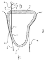
Figure 1 is a cross-sectional drawing of a hearing instrument shell residing in the ear canal, with a pull string affixed to an anchor inside the shell; -
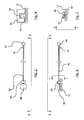
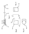
Figures 2-14 are drawings of various configurations of the pull string and the anchor ofFigure 1 ; -
Figure 15 is a cross-sectional drawing of a hearing instrument shell residing in the ear canal, with a pull string affixed to an anchor inside the shell, where the anchor and the pull string are embedded within the wall of the shell; -
Figure 16 is a flow chart of a process for locating the pull string and the anchor within the shell; and -
Figure 17 is a flow chart of a process for attaching the pull string to the hearing instrument shell. - A
hearing instrument shell 10 is shown residing in anear canal 20, between the inner and outer ears, inFigure 1 . Theshell 10 has afaceplate 30 attached to the shell at the point closest to the outer ear. A moldedpull string 40 is provided to aid in removal of theshell 10 from theear canal 10. Thepull string 40 has afree end 42 located outside theshell 10 and a fixedend 44 attached to an anchor 50 (depicted here schematically) on theinside wall 12 of theshell 10. Theshaft 46 of thepull string 40 passes through anopening 32 in thefaceplate 30. - The
anchor 50 may assume a number of configurations. For example, inFigure 2 , the anchor is apost 60 and the fixedend 44 of thepull string 40 is an annulus 70 that slips onto thepost 60. Thepost 60 is shown again in the elevation view ofFigure 3 , where the annulus 70 is illustrated in partial cross-section. Thepost 60 may be circular in cross section or have some other shape as desired -- square, triangular, etc. If thepost 60 has a non-circular cross section, thepull string 40 may be provided with a conforming opening in the fixedend 44. - Instead of the
post 60 and annulus 70 ofFigures 2 and 3 , thepull string 40 may be secured to theinside shell wall 12 by placing a restraining arch 80 (Figure 4 ) over theshaft 46 of the pull string 44 (shown in phantom). The fixedend 44 of thepull string 40 may be configured as adisk 90 or some other shape and size such that it cannot pass through theopening 82 in thearch 80. In lieu of adisk 90, the fixedend 44 of thepull string 40 may be fashioned as a sphere, a polyhedron, a half-disk, or any other suitable shape. Thearch 80, together with thepull string 40, is shown in the top, elevation, and partial cross-sectional views ofFigures 5-7 , respectively. - To further secure the fixed
end 44 of thepull string 40, a tab andpost assembly 100 may be positioned on theshell wall 12 behind thearch 80, as shown inFigures 8-11 . The tab andpost assembly 100 has a 102 tab that lays over thedisk 90. - Two
posts 110 may be substituted for thearch 80 as illustrated inFigures 12-14 . Theposts 110 may be fashioned as cylinders (as shown in the figures), or may utilize another cross section as desired. - To further conserve the use of space within the shell and provide structural support for the
pull string 40, a portion of thepull string shaft 46 may be embedded within thewall 14 of theshell 10, as shown inFigure 15 . Similarly, theanchor 50 may be fully or partially embedded within theshell wall 14. - The
pull string 40 may be fashioned from a material such as Vydyne 215PF natural nylon in an injection molding process. The material selected should be capable of withstanding a pull force of 15-20 Newtons. - The location of the
anchor 50 and thepull string 40 inside theshell 10 may be selected using collision detection methods to avoid conflicts with other components within theshell 10, as indicated in the flow chart ofFigure 16 . Initially, a computer model of thehearing instrument shell 10 is created. The components of the hearing instrument are then positioned within the shell model and a collision avoidance test is performed. A location within theshell 10 for thepull string 40 and theanchor 50 can then be chosen. Theshell 10, theanchor 50, and thepull string 40 can then be fabricated. - The foregoing process may be used to design the
hearing instrument shell 10 ofFigure 15 , with the understanding that a portion of thepull string shaft 46 and possibly all or part of theanchor 50 would be embedded within thewall 14 of theshell 10. - During assembly, the
fixed end 44 of thepull string 40 is attached to theanchor 50, as indicated in the flow chart ofFigure 17 . The fixedend 44 may be further secured to theanchor 50 by an adhesive such as a clear paste cured with ultraviolet light. - The
free end 42 of thepull string 40 may then be routed through anopening 32 in thefaceplate 30, and its length trimmed as desired. To enable the user to securely grasp thefree end 42 of thepull string 40, aball 48 or any other suitable structure may be attached to thefree end 42 and secured with an adhesive.
Claims (9)
- A hearing instrument shell assembly, comprising:a hearing instrument shell comprising an inside wall;a pull string comprising fixed and free ends; andan anchor secured to the inside wall of the hearing instrument shell that cooperatively engages the fixed end of the pull string.
- An assembly as set forth in claim 1, where
the fixed end comprises an annulus; and
the anchor comprises a post. - An assembly as set forth in claim 1, where
the pull string comprises a shaft between the fixed and the free ends; and
the anchor comprises a restraining arch through which the pull string shaft passes. - An assembly as set forth in claim 1, where the anchor comprises vertical posts through which the pull string shaft passes.
- An assembly as set forth in claim 1, where
the shell comprises a wall;
the pull string comprises a shaft between the fixed and the free ends, and a portion of the shaft is embedded within the wall. - An assembly as set forth in claim 5, where the anchor is at least partially embedded within the wall.
- A method for designing a hearing instrument shell comprising an interior volume and an inside wall, where the shell comprises components positioned within the interior volume and a pull string attached to an anchor on the inside wall of the shell, comprising:creating a computer model of a hearing instrument shell;locating the components within the computer model of the shell;performing a collision avoidance test;in response to the collision avoidance test, adjusting the location of the components within the computer model of the shell;locating the pull string within the computer model of the shell; andlocating the anchor on the inside wall of the computer model of the shell.
- A method as set forth in claim 7, further comprising embedding a portion of the pull string within the wall of the shell.
- A method as set forth in claim 8, further comprising embedding a portion of the anchor within the inside wall of the computer model of the shell.
Applications Claiming Priority (1)
| Application Number | Priority Date | Filing Date | Title |
|---|---|---|---|
| US12/210,353 US8280090B2 (en) | 2008-09-15 | 2008-09-15 | Molded pull string for custom hearing instruments |
Publications (2)
| Publication Number | Publication Date |
|---|---|
| EP2164284A2 true EP2164284A2 (en) | 2010-03-17 |
| EP2164284A3 EP2164284A3 (en) | 2013-11-27 |
Family
ID=41396222
Family Applications (1)
| Application Number | Title | Priority Date | Filing Date |
|---|---|---|---|
| EP09167626.2A Withdrawn EP2164284A3 (en) | 2008-09-15 | 2009-08-11 | Molded pull string for custom hearing instruments |
Country Status (2)
| Country | Link |
|---|---|
| US (1) | US8280090B2 (en) |
| EP (1) | EP2164284A3 (en) |
Families Citing this family (2)
| Publication number | Priority date | Publication date | Assignee | Title |
|---|---|---|---|---|
| US8758436B2 (en) * | 2009-09-17 | 2014-06-24 | Lawrence G. Clayton | Ear insert for relief of TMJ discomfort and headaches |
| DK3629599T3 (en) * | 2018-09-28 | 2022-01-10 | Gn Hearing As | HEARING DEVICE WHICH INCLUDES A LOOP ANTENNA |
Citations (2)
| Publication number | Priority date | Publication date | Assignee | Title |
|---|---|---|---|---|
| US20020196954A1 (en) | 2001-06-22 | 2002-12-26 | Marxen Christopher J. | Modeling and fabrication of three-dimensional irregular surfaces for hearing instruments |
| US6529609B1 (en) * | 1998-10-29 | 2003-03-04 | In'tech Industries, Inc. | Puller and methods of making and using the same |
Family Cites Families (4)
| Publication number | Priority date | Publication date | Assignee | Title |
|---|---|---|---|---|
| DE9213343U1 (en) * | 1991-10-16 | 1993-02-11 | N.V. Philips' Gloeilampenfabrieken, Eindhoven | Pull-out wire for attachment to a hearing aid |
| US7010137B1 (en) | 1997-03-12 | 2006-03-07 | Sarnoff Corporation | Hearing aid |
| US7256747B2 (en) * | 2004-01-30 | 2007-08-14 | Starkey Laboratories, Inc. | Method and apparatus for a wireless hearing aid antenna |
| JP4764887B2 (en) * | 2005-12-28 | 2011-09-07 | リオン株式会社 | Ear hole hearing aid |
-
2008
- 2008-09-15 US US12/210,353 patent/US8280090B2/en not_active Expired - Fee Related
-
2009
- 2009-08-11 EP EP09167626.2A patent/EP2164284A3/en not_active Withdrawn
Patent Citations (2)
| Publication number | Priority date | Publication date | Assignee | Title |
|---|---|---|---|---|
| US6529609B1 (en) * | 1998-10-29 | 2003-03-04 | In'tech Industries, Inc. | Puller and methods of making and using the same |
| US20020196954A1 (en) | 2001-06-22 | 2002-12-26 | Marxen Christopher J. | Modeling and fabrication of three-dimensional irregular surfaces for hearing instruments |
Also Published As
| Publication number | Publication date |
|---|---|
| US20100067724A1 (en) | 2010-03-18 |
| EP2164284A3 (en) | 2013-11-27 |
| US8280090B2 (en) | 2012-10-02 |
Similar Documents
| Publication | Publication Date | Title |
|---|---|---|
| EP2387346B1 (en) | Endoscope having a camera housing and method for making a camera housing | |
| AU2010236087B2 (en) | Headset with side support | |
| EP1853088A2 (en) | Ear mold | |
| JPS60103798A (en) | Displacement-type bone conduction microphone | |
| US20050074138A1 (en) | Feedback reducing receiver mount and assembly | |
| US8280090B2 (en) | Molded pull string for custom hearing instruments | |
| CN103875258A (en) | Method for manufacturing soft custom ear molds and soft custom ear molds | |
| EP1645165B1 (en) | Feedback reducing receiver assembly | |
| CN110276127B (en) | Statics control method for spiral pneumatic soft actuator | |
| JP6339356B2 (en) | Keyboard weight | |
| CN103782977A (en) | Rod tip segment and fishing rod with the same | |
| EP1768447A2 (en) | Insert molded surround with mechanical support | |
| TW200812477A (en) | Fishing rod | |
| CN101411322B (en) | Pole body for fishing rod and fishing rod | |
| AU2005332240A1 (en) | A hook for a hearing aid | |
| JP4518554B2 (en) | Fishing rod | |
| JP2007268125A (en) | Doll toy | |
| JP2005027587A (en) | Rod body and fishing rod | |
| CN211406210U (en) | Microphone support and microphone | |
| CN223628077U (en) | A simulated eye structure | |
| JP2006154183A (en) | Fixing member for optical connector | |
| AU2014280899B2 (en) | Ball chain connector and method of releasably connecting together ball chain ends | |
| JP2011024531A (en) | Fishing float | |
| JP6722003B2 (en) | How to configure the tip of a fishing rod | |
| CN212272758U (en) | Novel take out nail ring |
Legal Events
| Date | Code | Title | Description |
|---|---|---|---|
| PUAI | Public reference made under article 153(3) epc to a published international application that has entered the european phase |
Free format text: ORIGINAL CODE: 0009012 |
|
| AK | Designated contracting states |
Kind code of ref document: A2 Designated state(s): AT BE BG CH CY CZ DE DK EE ES FI FR GB GR HR HU IE IS IT LI LT LU LV MC MK MT NL NO PL PT RO SE SI SK SM TR |
|
| AX | Request for extension of the european patent |
Extension state: AL BA RS |
|
| RAP1 | Party data changed (applicant data changed or rights of an application transferred) |
Owner name: SIEMENS AUDIOLOGISCHE TECHNIK GMBH |
|
| RAP1 | Party data changed (applicant data changed or rights of an application transferred) |
Owner name: SIEMENS MEDICAL INSTRUMENTS PTE. LTD. |
|
| PUAL | Search report despatched |
Free format text: ORIGINAL CODE: 0009013 |
|
| AK | Designated contracting states |
Kind code of ref document: A3 Designated state(s): AT BE BG CH CY CZ DE DK EE ES FI FR GB GR HR HU IE IS IT LI LT LU LV MC MK MT NL NO PL PT RO SE SI SK SM TR |
|
| AX | Request for extension of the european patent |
Extension state: AL BA RS |
|
| RIC1 | Information provided on ipc code assigned before grant |
Ipc: H04R 25/00 20060101AFI20131023BHEP |
|
| 17P | Request for examination filed |
Effective date: 20140414 |
|
| RBV | Designated contracting states (corrected) |
Designated state(s): AT BE BG CH CY CZ DE DK EE ES FI FR GB GR HR HU IE IS IT LI LT LU LV MC MK MT NL NO PL PT RO SE SI SK SM TR |
|
| 17Q | First examination report despatched |
Effective date: 20150625 |
|
| RAP1 | Party data changed (applicant data changed or rights of an application transferred) |
Owner name: SIVANTOS PTE. LTD. |
|
| RAP1 | Party data changed (applicant data changed or rights of an application transferred) |
Owner name: SIVANTOS PTE. LTD. |
|
| STAA | Information on the status of an ep patent application or granted ep patent |
Free format text: STATUS: THE APPLICATION IS DEEMED TO BE WITHDRAWN |
|
| 18D | Application deemed to be withdrawn |
Effective date: 20180301 |