EP2164208A1 - Method for determining a data transport unit parameter for the communication between two stations in a network of stations, network device adapted to act as a sending station and network device adapted to act as a receiving station in the method - Google Patents
Method for determining a data transport unit parameter for the communication between two stations in a network of stations, network device adapted to act as a sending station and network device adapted to act as a receiving station in the method Download PDFInfo
- Publication number
- EP2164208A1 EP2164208A1 EP09008792A EP09008792A EP2164208A1 EP 2164208 A1 EP2164208 A1 EP 2164208A1 EP 09008792 A EP09008792 A EP 09008792A EP 09008792 A EP09008792 A EP 09008792A EP 2164208 A1 EP2164208 A1 EP 2164208A1
- Authority
- EP
- European Patent Office
- Prior art keywords
- mtu
- data transport
- network
- transport unit
- stations
- Prior art date
- Legal status (The legal status is an assumption and is not a legal conclusion. Google has not performed a legal analysis and makes no representation as to the accuracy of the status listed.)
- Granted
Links
Images



Classifications
-
- H—ELECTRICITY
- H04—ELECTRIC COMMUNICATION TECHNIQUE
- H04L—TRANSMISSION OF DIGITAL INFORMATION, e.g. TELEGRAPHIC COMMUNICATION
- H04L47/00—Traffic control in data switching networks
- H04L47/10—Flow control; Congestion control
- H04L47/36—Flow control; Congestion control by determining packet size, e.g. maximum transfer unit [MTU]
Definitions
- the invention concerns the technical field of a so-called Path MTU (Maximum Transmission Unit) Discovery process between two computing nodes over packet switched networks.
- Path MTU Maximum Transmission Unit
- Sending large packets reduces the packet header as well as the overall packet processing overhead and improves therefore the network-performance.
- Using packets bigger than the link MTU will lead to packet fragmentation or even worse - to loss of all data packets.
- the fragmentation produces unintentional header overhead and additional reassembly time or even in latter case lead to service disruption.
- On the path between two hosts in the network may exist various hops, e.g. routers, a packet needs to pass.
- Each link between two hops has its own MTU which may differ on each link. Thus there is a need for means to determine the maximum packet size, which can be transmitted from one end of communication to the other one without packet loss or fragmentation.
- the general path MTU discovery algorithm described in [Mo90] is based on sending probe packets with the DF (don't fragment) bit set in the IP header. Then any device along the path whose outgoing MTU is smaller than the packet, will drop it, and send back an ICMP (Internet Control Message Protocol) message "Fragmentation Needed" containing the actual MTU of the outgoing interface. Receiving this message allows the sending host to reduce its packet size appropriately. The process repeats until the MTU is small enough to traverse the entire path without fragmentation.
- the disadvantage of this method is the need to wait for an acknowledgment for each single sent probe packet. If a packet was dropped and the receiving host will not send an acknowledgement the sending host must need to wait until a timeout occurs to assume the used MTU was too big. In high delay networks the time needed to wait for the acknowledgement or the according timeout leads to high path MTU discovery durations and in consequence to long connection setup times.
- the proposed method is also based on sending probe packets with the DF bit set in the according IP header.
- the invention relies on acknowledgements of the probe packets sent by the destination host in the same way as in the binary search approach described in [Ma07].
- a common MTU search is done by sending probe packets with MTU sizes of common network technology based MTU values, similar to the "likely path MTU value" search described in [Mo90]. In order to find accurate path MTU values, similar MTUs are not grouped in plateaus. In addition, these common values increased by one byte are sent as well, to identify the effective path MTU is a common MTU or in between of two common MTUs.
- the probe packets should not be sent individually after the acknowledgement of the previous one arrived, but just sent in a bunch with a threshold data rate meaning that as many probe packets will be sent as the available data rate allows. In order to avoid the sending of 10Gbit/s peaks it is more appropriate to insert a pause between the transmissions of two probe packets.
- a grid MTU search will be applied to the search area left by the common MTU search.
- the grid MTU search can be performed as a highly parallelized binary search operation.
- the proposed path MTU discovery method the effective path MTU can be discovered much faster than the binary search approach and even than the common MTU search. Moreover, the proposed method does not rely on ICMP messages support of the network between the end systems of communication.
- Figure 1 shows a network with three hosts H1, H2, H3, two routers R1, R2 and the actual MTU value on each link.
- the path MTU between host H1 and host H2 is a common MTU value of 4500 Bytes, whereas the path MTU between host H1 and host H3 is an uncommon MTU of 6532 Bytes.
- MTU values are usually provided in units of Bytes. This however is just an example and not a limitation. If MTU values are used with different units like Bits, Dibits, Nibbles, Duplets, Triplets, Quadlets, etc. the method and device according the invention will work accordingly in similar fashion.
- a common MTU search is performed by sending probe packets with common MTU values. This search bases on the "likely path MTU value" search described in [Mo90].
- the requesting host is equipped with an MTU value table for this purpose. However, the intention is here to find accurate path MTU values, so no common MTU grouping is done here.
- Common MTU values are values given by commonly used network technologies, e.g. Ethernet, ATM, SONET, Infiniband, Interbus, CAN or WLAN. All probe packets are sent with the DF bit set in the IP header structure. To be independent from ICMP messages the algorithm relies on the reception of acknowledgments sent by the destination host for every received probe packet.
- Fig. 2 shows a path MTU discovery case, when it is performed according the invention with pairs of probe packets, one with a common MTU value and the other with the common MTU value increased by one.
- the search concerns the path between host H1 and host H2.
- the common MTU table consists of MTU values sized: 576, 1006, 1500, 4500, 8166, 9000.
- the first pair of probe packets concerns the MTU values 576 and 577. Both are acknowledged by host H2.
- probe packets for the value pair 1500 and 1501 are used. They are also acknowledged as seen in the drawing.
- probe packets for the MTU value pair 4500 and 4501 are sent.
- the packet with the value 4500 is acknowledged and the packet with the values 4501 is not acknowledged.
- the actual path MTU for the path between host H1 and host H2 via router R1 is determined and equals 4500 Bytes.
- the effective path MTU is an uncommon MTU value between the biggest acknowledged value and the following bigger unacknowledged common MTU value or the biggest acknowledged value itself.
- a grid MTU search will be performed in a second step.
- the sending host calculates the average Round Trip Time RTT existing between it and the destination host while receiving the acknowledgements during the search with common MTU values. Exactly this timeframe should be used by the grid MTU search to send probe packets covering the search area left by the step of searching with common MTU values.
- RTT Round Trip Time
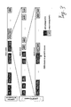
- Fig. 3 shows the more generic scenario, covered by the discovery case between host H1 and host H3.
- the packet with the size of 4501 bytes would be the last acknowledged MTU probe packet. So, the remaining area to cover is between: 4501 bytes (incremented common MTU value) and 8166 bytes.
- the last unacknowledged value will also be taken into account in this embodiment because it might be that this probe packet has been lost on the way to its destination so that it is safer to test this MTU value again.
- So 182 packets are sent, wherein each packet is made 20 byte bigger than the previous one.
- the binary search approach according to [Ma07] just quarters the initial area to about 900 values in the same time of two RTT times. After one additional cycle the grid search method will have found the effective path MTU, by contrast the binary search will take a time of about another 9 RTT to discover the effective path MTU.
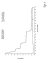
- Fig. 4 illustrates the duration advantage of the method according the invention against the binary search method according to [Ma07].
- the solid line represents the values for the combined search with the initial common values and refining grid search values and the dashed line represents the values for the binary search process. For a better comparability identical initial timeout values and timeout calculations were used in both methods.
- a brute-force linear search could be performed in alternative fashion.
- This approach is very simple to implement but it needs a multiple number of packets, which will unnecessarily flood the network with a high amount of probe packets during each path MTU discovery.
- Fig. 5 shows the essential difference between the number of sent packets used by the combined grid MTU search, proposed with this invention, and the brute-force linear search approach. In worst case the brute-force approach will need twenty times the amount of packets and in average still ten times more compared to the combined grid MTU search.
- the general idea of the invention is applicable in all cases where the round trip time RTT is the determining factor of the duration.
Landscapes
- Engineering & Computer Science (AREA)
- Computer Networks & Wireless Communication (AREA)
- Signal Processing (AREA)
- Data Exchanges In Wide-Area Networks (AREA)
Abstract
Description
- The invention concerns the technical field of a so-called Path MTU (Maximum Transmission Unit) Discovery process between two computing nodes over packet switched networks.
- Sending large packets reduces the packet header as well as the overall packet processing overhead and improves therefore the network-performance. Especially in high-bandwidth networks, e.g. 10GBit/s, it's essential to use large packets to fully utilize the link capacity. Using packets bigger than the link MTU will lead to packet fragmentation or even worse - to loss of all data packets. The fragmentation produces unintentional header overhead and additional reassembly time or even in latter case lead to service disruption. On the path between two hosts in the network may exist various hops, e.g. routers, a packet needs to pass. Each link between two hops has its own MTU which may differ on each link. Thus there is a need for means to determine the maximum packet size, which can be transmitted from one end of communication to the other one without packet loss or fragmentation.
-
- [Mo90] J. Mogul. Path MTU Discovery Specification. RFC 1191, IETF, November 1990
- [HA03] L. Hak-Goo, K. Young-Keun, K. Sun-Woo, L. Young-Jun. Method for path MTU discovery on IP network and apparatus thereof. Patent No.
US2003188015A1 , Samsung Electronics Co Ltd (US), October 2003 - [Ma07] M. Mathis, J. Heffner. Packetization Layer Path MTU Discovery Specification. RFC 4821, IETF, March 2007
- In the following, applicant refers to the above listed references in a simplified form by using only the short reference code provided in the list.
- The general path MTU discovery algorithm described in [Mo90] is based on sending probe packets with the DF (don't fragment) bit set in the IP header. Then any device along the path whose outgoing MTU is smaller than the packet, will drop it, and send back an ICMP (Internet Control Message Protocol) message "Fragmentation Needed" containing the actual MTU of the outgoing interface. Receiving this message allows the sending host to reduce its packet size appropriately. The process repeats until the MTU is small enough to traverse the entire path without fragmentation.
- The disadvantage of this algorithm and also of the discovery approach described in [HA03] is the dependency on receiving ICMP messages. However, security devices, e.g. firewalls, often block ICMP messages, including the ICMP error messages that are needed for these path MTU discovery algorithms to work.
- Another problem with the approach described in [Mo90] is a missing MTU value in the corresponding ICMP message. To deal with it, [Mo90] proposes a search for "likely path MTU values". This search bases on a common MTU table which contains several plateau values to cover the MTU value area. The "likely value" search will send probe packets with sizes from this table and assume the biggest plateau value, which was not answered by an ICMP error message, as path MTU.
- This approach still relies on ICMP messages and thus deals with the same disadvantages described before. Furthermore the accurate path MTU will not be found in any case, because similar "likely MTU values" are grouped in plateau values.
- The approach described in [Ma07] uses a binary search to work around the problem with dropped ICMP packets. The algorithm relies on the fact, that the sending host sends probe packets which need to be acknowledged by the receiving host. Depending on the reception of an explicit acknowledgement or not in case of a packet loss, the search area is narrowed setting the lower respectively the upper search limit for further searching.
- The disadvantage of this method is the need to wait for an acknowledgment for each single sent probe packet. If a packet was dropped and the receiving host will not send an acknowledgement the sending host must need to wait until a timeout occurs to assume the used MTU was too big. In high delay networks the time needed to wait for the acknowledgement or the according timeout leads to high path MTU discovery durations and in consequence to long connection setup times.
- It is an object of the invention to describe a method for a fast and byte accurate path MTU discovery not relying on ICMP messages.
- Like the above mentioned algorithms, the proposed method is also based on sending probe packets with the DF bit set in the according IP header. In order to deal with connections, on which ICMP messages are blocked within the network nodes, the invention relies on acknowledgements of the probe packets sent by the destination host in the same way as in the binary search approach described in [Ma07].
- In addition, at first, a common MTU search is done by sending probe packets with MTU sizes of common network technology based MTU values, similar to the "likely path MTU value" search described in [Mo90]. In order to find accurate path MTU values, similar MTUs are not grouped in plateaus. In addition, these common values increased by one byte are sent as well, to identify the effective path MTU is a common MTU or in between of two common MTUs.
- In an advanced embodiment of the invention contrary to the approaches described above the probe packets should not be sent individually after the acknowledgement of the previous one arrived, but just sent in a bunch with a threshold data rate meaning that as many probe packets will be sent as the available data rate allows. In order to avoid the sending of 10Gbit/s peaks it is more appropriate to insert a pause between the transmissions of two probe packets.
- In an even more advanced embodiment of the invention, if the common MTU search failed, meaning that the acknowledgements indicate that the path MTU lies in between two common MTU values, a grid MTU search will be applied to the search area left by the common MTU search.
- For an optimization it is an advantageous embodiment of the invention to base the grid width (size difference between two consecutive grid search probe packets) used for the grid search on the amount of packets that can be sent within one RTT (round trip time) of the network path. In this way, the grid MTU search can be performed as a highly parallelized binary search operation.
- With the proposed path MTU discovery method, the effective path MTU can be discovered much faster than the binary search approach and even than the common MTU search. Moreover, the proposed method does not rely on ICMP messages support of the network between the end systems of communication.
- Exemplary embodiments of the invention are shown in the drawings and are explained in greater detail in the following description.
- In the drawings:
- Fig. 1
- shows an example of a network with common and uncommon MTU values for the different branches;
- Fig. 2
- illustrates how a path MTU will be determined with the common MTU search process;
- Fig. 3
- illustrates how a path MTU will be determined according to the invention with the combined common and grid MTU search process;
- Fig. 4
- shows two graphs for comparing the resulting MTU search durations one according the binary search and the other for the MTU search according the invention;
- Fig. 5
- shows two graphs for comparing the amount of sent packets needed for determining the MTU value one according a combined common and linear search and the other for the MTU search according the invention.
-
Figure 1 shows a network with three hosts H1, H2, H3, two routers R1, R2 and the actual MTU value on each link. The path MTU between host H1 and host H2 is a common MTU value of 4500 Bytes, whereas the path MTU between host H1 and host H3 is an uncommon MTU of 6532 Bytes. MTU values are usually provided in units of Bytes. This however is just an example and not a limitation. If MTU values are used with different units like Bits, Dibits, Nibbles, Duplets, Triplets, Quadlets, etc. the method and device according the invention will work accordingly in similar fashion. - In an optimized embodiment of the invention there are two steps to discover the effective path MTU between two hosts.
- At first, a common MTU search is performed by sending probe packets with common MTU values. This search bases on the "likely path MTU value" search described in [Mo90]. The requesting host is equipped with an MTU value table for this purpose. However, the intention is here to find accurate path MTU values, so no common MTU grouping is done here. Common MTU values are values given by commonly used network technologies, e.g. Ethernet, ATM, SONET, Infiniband, Interbus, CAN or WLAN. All probe packets are sent with the DF bit set in the IP header structure. To be independent from ICMP messages the algorithm relies on the reception of acknowledgments sent by the destination host for every received probe packet. To make a fast path MTU discovery, all probe packets are sent in one bunch and not one single packet after the acknowledgment of the previous one has arrived. This may be restricted by the number of data packets which can be sent within one RTT. To determine the accurate size of MTU, it is insufficient to send only probe packets with those likely MTU sizes. The effective path MTU could still be between the biggest acknowledged common MTU value and the following bigger unacknowledged value. Therefore probe packets with common MTU values plus one are sent in addition to the plain common MTU values. If after that a common MTU value is the biggest acknowledged MTU it must be the effective path MTU due to the following bigger unacknowledged MTU is the next possible MTU value.
-
Fig. 2 shows a path MTU discovery case, when it is performed according the invention with pairs of probe packets, one with a common MTU value and the other with the common MTU value increased by one. The search concerns the path between host H1 and host H2. - Hereby, its presumed, that the common MTU table consists of MTU values sized: 576, 1006, 1500, 4500, 8166, 9000. Its evident from the drawing that the first pair of probe packets concerns the MTU values 576 and 577. Both are acknowledged by host H2. Next try concerns the probe packets for the
MTU value pair value pair MTU value pair value 4500 is acknowledged and the packet with thevalues 4501 is not acknowledged. In that example, the actual path MTU for the path between host H1 and host H2 via router R1 is determined and equals 4500 Bytes. - If one of the additional values is the biggest acknowledged MTU, the effective path MTU is an uncommon MTU value between the biggest acknowledged value and the following bigger unacknowledged common MTU value or the biggest acknowledged value itself.
- To figure out this uncommon MTU, a grid MTU search will be performed in a second step. In an advantageous embodiment of the invention, the sending host calculates the average Round Trip Time RTT existing between it and the destination host while receiving the acknowledgements during the search with common MTU values. Exactly this timeframe should be used by the grid MTU search to send probe packets covering the search area left by the step of searching with common MTU values. When receiving the first acknowledgement, the last probe packet was just sent. One grid MTU search cycle will take the time of twice the RTT, plus a packet timeout value in the worst case. One RTT is spent to send probe packets and another one to receive the according acknowledgments.
-
Fig. 3 shows the more generic scenario, covered by the discovery case between host H1 and host H3. In that example, during the search with common MTU values, the packet with the size of 4501 bytes would be the last acknowledged MTU probe packet. So, the remaining area to cover is between: 4501 bytes (incremented common MTU value) and 8166 bytes. The last unacknowledged value will also be taken into account in this embodiment because it might be that this probe packet has been lost on the way to its destination so that it is safer to test this MTU value again.
possible values: 8166 - 4501 = 3665 bytes
average RTT: 20ms
average time to send one probe packet: 0.11 ms/packet
number of probe packets sent in one RTT: 20 ms / 0.11 ms/packet ≈ 182 packets
grid width: 3665 byte / 182 packets ≈ 20 byte/packet - So 182 packets are sent, wherein each packet is made 20 byte bigger than the previous one.
- After one cycle consisting of two RTT times in the case above the left search area contains only twenty values. In comparison, the binary search approach according to [Ma07] just quarters the initial area to about 900 values in the same time of two RTT times. After one additional cycle the grid search method will have found the effective path MTU, by contrast the binary search will take a time of about another 9 RTT to discover the effective path MTU.
-
Fig. 4 illustrates the duration advantage of the method according the invention against the binary search method according to [Ma07]. The solid line represents the values for the combined search with the initial common values and refining grid search values and the dashed line represents the values for the binary search process. For a better comparability identical initial timeout values and timeout calculations were used in both methods. - To find an uncommon MTU value between two common MTU values a brute-force linear search could be performed in alternative fashion. This approach is very simple to implement but it needs a multiple number of packets, which will unnecessarily flood the network with a high amount of probe packets during each path MTU discovery.
Fig. 5 shows the essential difference between the number of sent packets used by the combined grid MTU search, proposed with this invention, and the brute-force linear search approach. In worst case the brute-force approach will need twenty times the amount of packets and in average still ten times more compared to the combined grid MTU search. - The general idea of the invention is applicable in all cases where the round trip time RTT is the determining factor of the duration.
Claims (10)
- Method for determining a data transport unit parameter for the communication between two stations (H1, H2, H3) in a network of stations, wherein for the data transport unit parameter a number of discrete values exists and for a communication path between a pair of stations in the network, an optimum value is existing depending on the used communication technology or network equipment configuration, wherein the optimum value is determined for the data transport unit parameter by sending probe data transport units according to the discrete data transport unit parameter values to the partner station, and evaluating the corresponding response messages from the partner station, characterized by the step of sending pairs of probe data transport units, each time one according to a set of standard values for the data transport unit parameter and the other according to the corresponding one from a set of values in which the standard values are increased by a minimum possible increment.
- Method according to claim 1, further characterized by the step of sending a plurality of the probe data transport units without waiting for the corresponding response messages.
- Method according to claim 1 or 2, wherein in the probe data transport units a marker information item is set to indicate that the fragmentation of the probe data transport unit is forbidden.
- Method according to claim 3, wherein any device along the communication path for a pair of stations responds to the probe data transport unit with a message that indicates that the received probe data transport unit is dropped and requires fragmentation in case the next section on the communication path in sending direction has a limited transport characteristic which is exceeded by the probe data transport unit according to the set data transport unit parameter.
- Method according to one of the previous claims wherein a grid search is performed for finding the optimum data transport parameter in the range between the two values from the set of standard values between which the maximum possible value shall be according to the evaluation of the response messages.
- Method according to claim 5, characterized by a step of determining the round trip time RTT for the network path between the sending host (H1) and the destination host (H3), in particular the average round trip time, wherein the round trip time RTT is used for determining the grid width for the grid search so that the probe packets for the grid search can be sent within one round trip time RTT.
- Method according to one of the previous claims, in which the maximum possible value concerns the parameter of the maximum transmission unit MTU, which defines the maximum data packet length supported in the used communication protocol for that section of the communication path.
- Method according to one of claims 3 to 7, wherein the marker information item is the Don't Fragment DF bit in an Internet Protocol IP packet header.
- Network device adapted to act as a sending station of a pair of network stations in the method according to one of the previous claims.
- Network device adapted to act as a receiving station of a pair of network stations in the method according to one of the claims 1 to 8.
Priority Applications (2)
| Application Number | Priority Date | Filing Date | Title |
|---|---|---|---|
| EP09008792.5A EP2164208B1 (en) | 2008-09-15 | 2009-07-04 | Method for determining a data transport unit parameter for the communication between two stations in a network of stations and network device adapted to act as a sending station |
| US12/584,301 US8289857B2 (en) | 2008-09-15 | 2009-09-03 | Method for determining a data transport unit parameter for the communication between two stations in a network of stations, network device adapted to act as a sending station and network device adapted to act as a receiving station in the method |
Applications Claiming Priority (2)
| Application Number | Priority Date | Filing Date | Title |
|---|---|---|---|
| EP08305551 | 2008-09-15 | ||
| EP09008792.5A EP2164208B1 (en) | 2008-09-15 | 2009-07-04 | Method for determining a data transport unit parameter for the communication between two stations in a network of stations and network device adapted to act as a sending station |
Publications (2)
| Publication Number | Publication Date |
|---|---|
| EP2164208A1 true EP2164208A1 (en) | 2010-03-17 |
| EP2164208B1 EP2164208B1 (en) | 2014-01-01 |
Family
ID=41051055
Family Applications (1)
| Application Number | Title | Priority Date | Filing Date |
|---|---|---|---|
| EP09008792.5A Not-in-force EP2164208B1 (en) | 2008-09-15 | 2009-07-04 | Method for determining a data transport unit parameter for the communication between two stations in a network of stations and network device adapted to act as a sending station |
Country Status (2)
| Country | Link |
|---|---|
| US (1) | US8289857B2 (en) |
| EP (1) | EP2164208B1 (en) |
Cited By (1)
| Publication number | Priority date | Publication date | Assignee | Title |
|---|---|---|---|---|
| US20160218962A1 (en) * | 2015-01-26 | 2016-07-28 | Mediatek Inc. | Maximum Transmission Unit Size Reporting and Discovery by a User Equipment |
Families Citing this family (4)
| Publication number | Priority date | Publication date | Assignee | Title |
|---|---|---|---|---|
| US9069727B2 (en) * | 2011-08-12 | 2015-06-30 | Talari Networks Incorporated | Adaptive private network with geographically redundant network control nodes |
| US20110274120A1 (en) * | 2010-05-06 | 2011-11-10 | International Business Machines Corporation | Network data packet framentation and reassembly method |
| KR20150093219A (en) * | 2012-12-18 | 2015-08-17 | 코닌클리즈케 케이피엔 엔.브이. | Probing a network |
| CN104128541B (en) * | 2014-07-24 | 2016-03-30 | 无锡尚德太阳能电力有限公司 | The method of embossing is made on photovoltaic welding belt surface |
Citations (1)
| Publication number | Priority date | Publication date | Assignee | Title |
|---|---|---|---|---|
| US20030188015A1 (en) | 2002-03-29 | 2003-10-02 | Samsung Electronics Co., Ltd. | Method for path MTU discovery on IP network and apparatus thereof |
Family Cites Families (5)
| Publication number | Priority date | Publication date | Assignee | Title |
|---|---|---|---|---|
| JP2853701B2 (en) * | 1997-03-18 | 1999-02-03 | 日本電気株式会社 | Terminal flow control method in ATM network |
| US7472314B2 (en) * | 2003-09-26 | 2008-12-30 | Alcatel - Lucent Usa Inc. | System and method for monitoring link delays and faults in an IP network |
| US7558604B2 (en) * | 2005-11-25 | 2009-07-07 | Lenovo (Singapore) Pte. Ltd. | Method and apparatus for remote discovery of client and access point settings in a wireless LAN |
| US20070214379A1 (en) * | 2006-03-03 | 2007-09-13 | Qualcomm Incorporated | Transmission control for wireless communication networks |
| ATE520221T1 (en) * | 2006-06-09 | 2011-08-15 | Ericsson Telefon Ab L M | DATA TRANSFER PATH EVALUATION USING FILTERING AND CHANGE DETECTION |
-
2009
- 2009-07-04 EP EP09008792.5A patent/EP2164208B1/en not_active Not-in-force
- 2009-09-03 US US12/584,301 patent/US8289857B2/en not_active Expired - Fee Related
Patent Citations (1)
| Publication number | Priority date | Publication date | Assignee | Title |
|---|---|---|---|---|
| US20030188015A1 (en) | 2002-03-29 | 2003-10-02 | Samsung Electronics Co., Ltd. | Method for path MTU discovery on IP network and apparatus thereof |
Non-Patent Citations (3)
| Title |
|---|
| J. MOGUL.: "Path MTU Discovery Specification. RFC 1191", IETF, November 1990 (1990-11-01) |
| M. MATHIS; J. HEFFNER: "Packetization Layer Path MTU Discovery Specification", RFC 4821, IETF, March 2007 (2007-03-01) |
| MATTHEW LUCKIE, UNIVERSITY OF WAIKATO; KENJIRO CHO, INTERNET INITIATIVE JAPAN; BILL OWENS, NYSERNET: "Inferring and Debugging Path MTU Discovery Failures", IMC '05, 2005 INTERNET MEASUREMENT CONFERENCE, 24 October 2005 (2005-10-24), pages 193 - 198, XP002545466, Retrieved from the Internet <URL:http://www.usenix.org/event/imc05/tech/luckie.html> [retrieved on 20090911] * |
Cited By (6)
| Publication number | Priority date | Publication date | Assignee | Title |
|---|---|---|---|---|
| US20160218962A1 (en) * | 2015-01-26 | 2016-07-28 | Mediatek Inc. | Maximum Transmission Unit Size Reporting and Discovery by a User Equipment |
| US9787596B2 (en) * | 2015-01-26 | 2017-10-10 | Mediatek Inc. | Maximum transmission unit size reporting and discovery by a user equipment |
| US10142250B2 (en) | 2015-01-26 | 2018-11-27 | Hfi Innovation Inc. | Maximum transmission unit size reporting using AT commands |
| US10142251B2 (en) | 2015-01-26 | 2018-11-27 | Hfi Innovation Inc. | Control of maximum transmission unit size discovery using AT commands |
| US10686713B2 (en) | 2015-01-26 | 2020-06-16 | Hfi Innovation Inc. | Maximum transmission unit size reporting using AT commands |
| US10708190B2 (en) | 2015-01-26 | 2020-07-07 | Hfi Innovation Inc. | Control of maximum transmission unit size discovery using AT commands |
Also Published As
| Publication number | Publication date |
|---|---|
| EP2164208B1 (en) | 2014-01-01 |
| US20100067397A1 (en) | 2010-03-18 |
| US8289857B2 (en) | 2012-10-16 |
Similar Documents
| Publication | Publication Date | Title |
|---|---|---|
| US11159423B2 (en) | Techniques for efficient multipath transmission | |
| EP3278514B1 (en) | Data transmission | |
| JP5816718B2 (en) | Communication apparatus, communication system, and data communication relay method | |
| Zhou et al. | Goodput improvement for multipath TCP by congestion window adaptation in multi-radio devices | |
| EP2979407B1 (en) | Re-marking of packets for queue control | |
| EP3820088A1 (en) | Method and network device for multi-path communication | |
| CN107645409B (en) | Method and device for determining transmission fault reason of data | |
| EP3281380B1 (en) | Method and system for the scheduling of packets in a bundling scenario based on tcp tunnels and native tcp information | |
| EP2164208B1 (en) | Method for determining a data transport unit parameter for the communication between two stations in a network of stations and network device adapted to act as a sending station | |
| EP2784997A1 (en) | Re-marking of packets for congestion control | |
| Alheid et al. | An analysis of the impact of out-of-order recovery algorithms on MPTCP throughput | |
| KR20040027176A (en) | congestion control method over wireless link | |
| US20050201375A1 (en) | Uninterrupted transfer method in IP network in the event of line failure | |
| JP5506591B2 (en) | Communication system and communication quality control method | |
| EP2391068A1 (en) | Provision of path characterisation information in networks | |
| Iyengar et al. | Making SCTP more robust to changeover | |
| Lane et al. | Best-effort network layer packet reordering in support of multipath overlay packet dispersion | |
| CN100471197C (en) | Method for efficiently sending/receiving data using mobile dedicated network transport layer, network device | |
| Rüngeler et al. | Congestion and flow control in the context of the message-oriented protocol SCTP | |
| Zhu et al. | Throughput of high-speed TCP in optical burst switching networks | |
| US7242685B1 (en) | System and method for initiating multilink fragment reassembly | |
| Kharche et al. | Impact of retransmission policies on performance of concurrent multipath transfers in wireless heterogeneous networks | |
| Tanaka et al. | Pulsed ACK: Improving robustness of TCP for asymmetric bandwidth | |
| Patel et al. | Reliable Connectionless Transport Protocol for Fast Message Delivery | |
| Yang et al. | Improving TCP performance by utilizing the BDP-aware mechanism |
Legal Events
| Date | Code | Title | Description |
|---|---|---|---|
| PUAI | Public reference made under article 153(3) epc to a published international application that has entered the european phase |
Free format text: ORIGINAL CODE: 0009012 |
|
| AK | Designated contracting states |
Kind code of ref document: A1 Designated state(s): AT BE BG CH CY CZ DE DK EE ES FI FR GB GR HR HU IE IS IT LI LT LU LV MC MK MT NL NO PL PT RO SE SI SK SM TR |
|
| AX | Request for extension of the european patent |
Extension state: AL BA RS |
|
| 17P | Request for examination filed |
Effective date: 20100907 |
|
| RAP1 | Party data changed (applicant data changed or rights of an application transferred) |
Owner name: TIXEL GMBH |
|
| 17Q | First examination report despatched |
Effective date: 20101014 |
|
| REG | Reference to a national code |
Ref country code: DE Ref legal event code: R079 Ref document number: 602009021092 Country of ref document: DE Free format text: PREVIOUS MAIN CLASS: H04L0012560000 Ipc: H04L0012801000 |
|
| RIC1 | Information provided on ipc code assigned before grant |
Ipc: H04L 12/805 20130101ALI20130627BHEP Ipc: H04L 12/801 20130101AFI20130627BHEP |
|
| GRAP | Despatch of communication of intention to grant a patent |
Free format text: ORIGINAL CODE: EPIDOSNIGR1 |
|
| INTG | Intention to grant announced |
Effective date: 20130829 |
|
| GRAS | Grant fee paid |
Free format text: ORIGINAL CODE: EPIDOSNIGR3 |
|
| GRAA | (expected) grant |
Free format text: ORIGINAL CODE: 0009210 |
|
| AK | Designated contracting states |
Kind code of ref document: B1 Designated state(s): AT BE BG CH CY CZ DE DK EE ES FI FR GB GR HR HU IE IS IT LI LT LU LV MC MK MT NL NO PL PT RO SE SI SK SM TR |
|
| REG | Reference to a national code |
Ref country code: GB Ref legal event code: FG4D |
|
| REG | Reference to a national code |
Ref country code: CH Ref legal event code: EP |
|
| REG | Reference to a national code |
Ref country code: IE Ref legal event code: FG4D |
|
| REG | Reference to a national code |
Ref country code: GB Ref legal event code: 746 Effective date: 20140120 |
|
| REG | Reference to a national code |
Ref country code: AT Ref legal event code: REF Ref document number: 648011 Country of ref document: AT Kind code of ref document: T Effective date: 20140215 |
|
| REG | Reference to a national code |
Ref country code: DE Ref legal event code: R096 Ref document number: 602009021092 Country of ref document: DE Effective date: 20140220 |
|
| REG | Reference to a national code |
Ref country code: DE Ref legal event code: R084 Ref document number: 602009021092 Country of ref document: DE Effective date: 20140116 |
|
| REG | Reference to a national code |
Ref country code: NL Ref legal event code: VDEP Effective date: 20140101 |
|
| REG | Reference to a national code |
Ref country code: AT Ref legal event code: MK05 Ref document number: 648011 Country of ref document: AT Kind code of ref document: T Effective date: 20140101 |
|
| REG | Reference to a national code |
Ref country code: LT Ref legal event code: MG4D |
|
| PG25 | Lapsed in a contracting state [announced via postgrant information from national office to epo] |
Ref country code: IS Free format text: LAPSE BECAUSE OF FAILURE TO SUBMIT A TRANSLATION OF THE DESCRIPTION OR TO PAY THE FEE WITHIN THE PRESCRIBED TIME-LIMIT Effective date: 20140501 Ref country code: LT Free format text: LAPSE BECAUSE OF FAILURE TO SUBMIT A TRANSLATION OF THE DESCRIPTION OR TO PAY THE FEE WITHIN THE PRESCRIBED TIME-LIMIT Effective date: 20140101 |
|
| PG25 | Lapsed in a contracting state [announced via postgrant information from national office to epo] |
Ref country code: NL Free format text: LAPSE BECAUSE OF FAILURE TO SUBMIT A TRANSLATION OF THE DESCRIPTION OR TO PAY THE FEE WITHIN THE PRESCRIBED TIME-LIMIT Effective date: 20140101 Ref country code: AT Free format text: LAPSE BECAUSE OF FAILURE TO SUBMIT A TRANSLATION OF THE DESCRIPTION OR TO PAY THE FEE WITHIN THE PRESCRIBED TIME-LIMIT Effective date: 20140101 Ref country code: CY Free format text: LAPSE BECAUSE OF FAILURE TO SUBMIT A TRANSLATION OF THE DESCRIPTION OR TO PAY THE FEE WITHIN THE PRESCRIBED TIME-LIMIT Effective date: 20140101 Ref country code: PT Free format text: LAPSE BECAUSE OF FAILURE TO SUBMIT A TRANSLATION OF THE DESCRIPTION OR TO PAY THE FEE WITHIN THE PRESCRIBED TIME-LIMIT Effective date: 20140502 Ref country code: ES Free format text: LAPSE BECAUSE OF FAILURE TO SUBMIT A TRANSLATION OF THE DESCRIPTION OR TO PAY THE FEE WITHIN THE PRESCRIBED TIME-LIMIT Effective date: 20140101 Ref country code: SE Free format text: LAPSE BECAUSE OF FAILURE TO SUBMIT A TRANSLATION OF THE DESCRIPTION OR TO PAY THE FEE WITHIN THE PRESCRIBED TIME-LIMIT Effective date: 20140101 Ref country code: FI Free format text: LAPSE BECAUSE OF FAILURE TO SUBMIT A TRANSLATION OF THE DESCRIPTION OR TO PAY THE FEE WITHIN THE PRESCRIBED TIME-LIMIT Effective date: 20140101 |
|
| PG25 | Lapsed in a contracting state [announced via postgrant information from national office to epo] |
Ref country code: HR Free format text: LAPSE BECAUSE OF FAILURE TO SUBMIT A TRANSLATION OF THE DESCRIPTION OR TO PAY THE FEE WITHIN THE PRESCRIBED TIME-LIMIT Effective date: 20140101 Ref country code: LV Free format text: LAPSE BECAUSE OF FAILURE TO SUBMIT A TRANSLATION OF THE DESCRIPTION OR TO PAY THE FEE WITHIN THE PRESCRIBED TIME-LIMIT Effective date: 20140101 Ref country code: BE Free format text: LAPSE BECAUSE OF FAILURE TO SUBMIT A TRANSLATION OF THE DESCRIPTION OR TO PAY THE FEE WITHIN THE PRESCRIBED TIME-LIMIT Effective date: 20140101 |
|
| REG | Reference to a national code |
Ref country code: DE Ref legal event code: R097 Ref document number: 602009021092 Country of ref document: DE |
|
| PG25 | Lapsed in a contracting state [announced via postgrant information from national office to epo] |
Ref country code: DK Free format text: LAPSE BECAUSE OF FAILURE TO SUBMIT A TRANSLATION OF THE DESCRIPTION OR TO PAY THE FEE WITHIN THE PRESCRIBED TIME-LIMIT Effective date: 20140101 Ref country code: RO Free format text: LAPSE BECAUSE OF FAILURE TO SUBMIT A TRANSLATION OF THE DESCRIPTION OR TO PAY THE FEE WITHIN THE PRESCRIBED TIME-LIMIT Effective date: 20140101 Ref country code: EE Free format text: LAPSE BECAUSE OF FAILURE TO SUBMIT A TRANSLATION OF THE DESCRIPTION OR TO PAY THE FEE WITHIN THE PRESCRIBED TIME-LIMIT Effective date: 20140101 Ref country code: CZ Free format text: LAPSE BECAUSE OF FAILURE TO SUBMIT A TRANSLATION OF THE DESCRIPTION OR TO PAY THE FEE WITHIN THE PRESCRIBED TIME-LIMIT Effective date: 20140101 |
|
| PLBE | No opposition filed within time limit |
Free format text: ORIGINAL CODE: 0009261 |
|
| STAA | Information on the status of an ep patent application or granted ep patent |
Free format text: STATUS: NO OPPOSITION FILED WITHIN TIME LIMIT |
|
| PG25 | Lapsed in a contracting state [announced via postgrant information from national office to epo] |
Ref country code: PL Free format text: LAPSE BECAUSE OF FAILURE TO SUBMIT A TRANSLATION OF THE DESCRIPTION OR TO PAY THE FEE WITHIN THE PRESCRIBED TIME-LIMIT Effective date: 20140101 Ref country code: SK Free format text: LAPSE BECAUSE OF FAILURE TO SUBMIT A TRANSLATION OF THE DESCRIPTION OR TO PAY THE FEE WITHIN THE PRESCRIBED TIME-LIMIT Effective date: 20140101 |
|
| 26N | No opposition filed |
Effective date: 20141002 |
|
| REG | Reference to a national code |
Ref country code: DE Ref legal event code: R097 Ref document number: 602009021092 Country of ref document: DE Effective date: 20141002 |
|
| PG25 | Lapsed in a contracting state [announced via postgrant information from national office to epo] |
Ref country code: LU Free format text: LAPSE BECAUSE OF FAILURE TO SUBMIT A TRANSLATION OF THE DESCRIPTION OR TO PAY THE FEE WITHIN THE PRESCRIBED TIME-LIMIT Effective date: 20140704 |
|
| REG | Reference to a national code |
Ref country code: CH Ref legal event code: PL |
|
| REG | Reference to a national code |
Ref country code: IE Ref legal event code: MM4A |
|
| PG25 | Lapsed in a contracting state [announced via postgrant information from national office to epo] |
Ref country code: LI Free format text: LAPSE BECAUSE OF NON-PAYMENT OF DUE FEES Effective date: 20140731 Ref country code: CH Free format text: LAPSE BECAUSE OF NON-PAYMENT OF DUE FEES Effective date: 20140731 |
|
| PG25 | Lapsed in a contracting state [announced via postgrant information from national office to epo] |
Ref country code: SI Free format text: LAPSE BECAUSE OF FAILURE TO SUBMIT A TRANSLATION OF THE DESCRIPTION OR TO PAY THE FEE WITHIN THE PRESCRIBED TIME-LIMIT Effective date: 20140101 |
|
| PG25 | Lapsed in a contracting state [announced via postgrant information from national office to epo] |
Ref country code: IE Free format text: LAPSE BECAUSE OF NON-PAYMENT OF DUE FEES Effective date: 20140704 |
|
| PG25 | Lapsed in a contracting state [announced via postgrant information from national office to epo] |
Ref country code: SM Free format text: LAPSE BECAUSE OF FAILURE TO SUBMIT A TRANSLATION OF THE DESCRIPTION OR TO PAY THE FEE WITHIN THE PRESCRIBED TIME-LIMIT Effective date: 20140101 Ref country code: NO Free format text: LAPSE BECAUSE OF FAILURE TO SUBMIT A TRANSLATION OF THE DESCRIPTION OR TO PAY THE FEE WITHIN THE PRESCRIBED TIME-LIMIT Effective date: 20140401 Ref country code: MC Free format text: LAPSE BECAUSE OF FAILURE TO SUBMIT A TRANSLATION OF THE DESCRIPTION OR TO PAY THE FEE WITHIN THE PRESCRIBED TIME-LIMIT Effective date: 20140101 |
|
| PG25 | Lapsed in a contracting state [announced via postgrant information from national office to epo] |
Ref country code: GR Free format text: LAPSE BECAUSE OF FAILURE TO SUBMIT A TRANSLATION OF THE DESCRIPTION OR TO PAY THE FEE WITHIN THE PRESCRIBED TIME-LIMIT Effective date: 20140402 Ref country code: MT Free format text: LAPSE BECAUSE OF FAILURE TO SUBMIT A TRANSLATION OF THE DESCRIPTION OR TO PAY THE FEE WITHIN THE PRESCRIBED TIME-LIMIT Effective date: 20140101 Ref country code: BG Free format text: LAPSE BECAUSE OF FAILURE TO SUBMIT A TRANSLATION OF THE DESCRIPTION OR TO PAY THE FEE WITHIN THE PRESCRIBED TIME-LIMIT Effective date: 20140101 Ref country code: IT Free format text: LAPSE BECAUSE OF FAILURE TO SUBMIT A TRANSLATION OF THE DESCRIPTION OR TO PAY THE FEE WITHIN THE PRESCRIBED TIME-LIMIT Effective date: 20140101 |
|
| REG | Reference to a national code |
Ref country code: FR Ref legal event code: PLFP Year of fee payment: 8 |
|
| PG25 | Lapsed in a contracting state [announced via postgrant information from national office to epo] |
Ref country code: TR Free format text: LAPSE BECAUSE OF FAILURE TO SUBMIT A TRANSLATION OF THE DESCRIPTION OR TO PAY THE FEE WITHIN THE PRESCRIBED TIME-LIMIT Effective date: 20140101 Ref country code: HU Free format text: LAPSE BECAUSE OF FAILURE TO SUBMIT A TRANSLATION OF THE DESCRIPTION OR TO PAY THE FEE WITHIN THE PRESCRIBED TIME-LIMIT; INVALID AB INITIO Effective date: 20090704 |
|
| REG | Reference to a national code |
Ref country code: FR Ref legal event code: PLFP Year of fee payment: 9 |
|
| PG25 | Lapsed in a contracting state [announced via postgrant information from national office to epo] |
Ref country code: MK Free format text: LAPSE BECAUSE OF FAILURE TO SUBMIT A TRANSLATION OF THE DESCRIPTION OR TO PAY THE FEE WITHIN THE PRESCRIBED TIME-LIMIT Effective date: 20140101 |
|
| REG | Reference to a national code |
Ref country code: FR Ref legal event code: PLFP Year of fee payment: 10 |
|
| REG | Reference to a national code |
Ref country code: DE Ref legal event code: R079 Ref document number: 602009021092 Country of ref document: DE Free format text: PREVIOUS MAIN CLASS: H04L0012801000 Ipc: H04L0047100000 |
|
| REG | Reference to a national code |
Ref country code: FR Ref legal event code: PLFP Year of fee payment: 14 |
|
| PGFP | Annual fee paid to national office [announced via postgrant information from national office to epo] |
Ref country code: GB Payment date: 20230705 Year of fee payment: 15 |
|
| PGFP | Annual fee paid to national office [announced via postgrant information from national office to epo] |
Ref country code: FR Payment date: 20230705 Year of fee payment: 15 Ref country code: DE Payment date: 20230706 Year of fee payment: 15 |
|
| REG | Reference to a national code |
Ref country code: DE Ref legal event code: R119 Ref document number: 602009021092 Country of ref document: DE |
|
| GBPC | Gb: european patent ceased through non-payment of renewal fee |
Effective date: 20240704 |
|
| PG25 | Lapsed in a contracting state [announced via postgrant information from national office to epo] |
Ref country code: DE Free format text: LAPSE BECAUSE OF NON-PAYMENT OF DUE FEES Effective date: 20250201 |
|
| PG25 | Lapsed in a contracting state [announced via postgrant information from national office to epo] |
Ref country code: FR Free format text: LAPSE BECAUSE OF NON-PAYMENT OF DUE FEES Effective date: 20240731 |
|
| PG25 | Lapsed in a contracting state [announced via postgrant information from national office to epo] |
Ref country code: GB Free format text: LAPSE BECAUSE OF NON-PAYMENT OF DUE FEES Effective date: 20240704 |