EP2164181A1 - Method for mapping downlink dedicated pilot frequencies of extend cyclic prefix frame structure to physical resource blocks - Google Patents
Method for mapping downlink dedicated pilot frequencies of extend cyclic prefix frame structure to physical resource blocks Download PDFInfo
- Publication number
- EP2164181A1 EP2164181A1 EP08873412A EP08873412A EP2164181A1 EP 2164181 A1 EP2164181 A1 EP 2164181A1 EP 08873412 A EP08873412 A EP 08873412A EP 08873412 A EP08873412 A EP 08873412A EP 2164181 A1 EP2164181 A1 EP 2164181A1
- Authority
- EP
- European Patent Office
- Prior art keywords
- downlink dedicated
- domain
- time domain
- mapping
- mapped
- Prior art date
- Legal status (The legal status is an assumption and is not a legal conclusion. Google has not performed a legal analysis and makes no representation as to the accuracy of the status listed.)
- Ceased
Links
- 238000013507 mapping Methods 0.000 title claims abstract description 88
- 238000000034 method Methods 0.000 title claims abstract description 57
- 125000004122 cyclic group Chemical group 0.000 title claims abstract description 5
- 230000007774 longterm Effects 0.000 claims abstract description 4
- 239000013256 coordination polymer Substances 0.000 claims description 12
- 238000012545 processing Methods 0.000 claims description 2
- 238000010586 diagram Methods 0.000 description 7
- 238000013461 design Methods 0.000 description 4
- 238000005070 sampling Methods 0.000 description 4
- 230000001427 coherent effect Effects 0.000 description 2
- 238000000605 extraction Methods 0.000 description 2
- 238000012986 modification Methods 0.000 description 2
- 230000004048 modification Effects 0.000 description 2
- 230000001105 regulatory effect Effects 0.000 description 2
- 239000002356 single layer Substances 0.000 description 2
- 230000009286 beneficial effect Effects 0.000 description 1
- 238000001514 detection method Methods 0.000 description 1
- 238000005562 fading Methods 0.000 description 1
Images



Classifications
-
- H—ELECTRICITY
- H04—ELECTRIC COMMUNICATION TECHNIQUE
- H04L—TRANSMISSION OF DIGITAL INFORMATION, e.g. TELEGRAPHIC COMMUNICATION
- H04L27/00—Modulated-carrier systems
- H04L27/26—Systems using multi-frequency codes
- H04L27/2601—Multicarrier modulation systems
- H04L27/2602—Signal structure
- H04L27/2605—Symbol extensions, e.g. Zero Tail, Unique Word [UW]
- H04L27/2607—Cyclic extensions
-
- H—ELECTRICITY
- H04—ELECTRIC COMMUNICATION TECHNIQUE
- H04L—TRANSMISSION OF DIGITAL INFORMATION, e.g. TELEGRAPHIC COMMUNICATION
- H04L27/00—Modulated-carrier systems
- H04L27/26—Systems using multi-frequency codes
- H04L27/2601—Multicarrier modulation systems
- H04L27/2602—Signal structure
- H04L27/261—Details of reference signals
-
- H—ELECTRICITY
- H04—ELECTRIC COMMUNICATION TECHNIQUE
- H04L—TRANSMISSION OF DIGITAL INFORMATION, e.g. TELEGRAPHIC COMMUNICATION
- H04L5/00—Arrangements affording multiple use of the transmission path
- H04L5/003—Arrangements for allocating sub-channels of the transmission path
- H04L5/0048—Allocation of pilot signals, i.e. of signals known to the receiver
- H04L5/0051—Allocation of pilot signals, i.e. of signals known to the receiver of dedicated pilots, i.e. pilots destined for a single user or terminal
-
- H—ELECTRICITY
- H04—ELECTRIC COMMUNICATION TECHNIQUE
- H04B—TRANSMISSION
- H04B7/00—Radio transmission systems, i.e. using radiation field
- H04B7/02—Diversity systems; Multi-antenna system, i.e. transmission or reception using multiple antennas
- H04B7/04—Diversity systems; Multi-antenna system, i.e. transmission or reception using multiple antennas using two or more spaced independent antennas
- H04B7/06—Diversity systems; Multi-antenna system, i.e. transmission or reception using multiple antennas using two or more spaced independent antennas at the transmitting station
- H04B7/0613—Diversity systems; Multi-antenna system, i.e. transmission or reception using multiple antennas using two or more spaced independent antennas at the transmitting station using simultaneous transmission
- H04B7/068—Diversity systems; Multi-antenna system, i.e. transmission or reception using multiple antennas using two or more spaced independent antennas at the transmitting station using simultaneous transmission using space frequency diversity
Definitions
- the present invention relates generally to the field of wireless communications, and relates more specifically to a method for mapping downlink dedicated pilots to resource elements in Extended Cyclic Prefix (Extended CP) frame structure in a Long Term Evolution (LTE) system.
- Extended Cyclic Prefix Extended CP
- LTE Long Term Evolution
- the overhead of reference signals will be quite great, and there will be a difference in real channel information estimated by uplink/downlink, so the beamforming weight-value feedback information is still needed to be estimated on the real channel information.
- the present invention provides a method for mapping downlink dedicated pilots to resource elements in Extended CP frame structure, so as to support a beamforming with lower overhead and superior performance.
- the method for mapping downlink dedicated pilots to resource elements in Extended CP frame structure in the present invention comprises the following steps:
- the preset regulation is: twelve subcarriers are mapped to a physical resource block in the frequency domain, four downlink dedicated pilots are mapped in a same time domain, and the dedicated pilots are two subcarriers apart.
- the corresponding time-domain position of the specific position is the 5 th orthogonal frequency division multiplexing symbol, and the corresponding frequency-domain position thereof is the same subcarrier of the first column of cell-specific reference signals in a physical resource block.
- a physical resource block comprises twelve subcarriers in the frequency domain, and twelve orthogonal frequency division multiplexing symbols in the time domain, and the mapping method comprises specifically:
- B and C are 1 or 2 or 3.
- each port of downlink dedicated pilots in a physical resource block there are multiple ports of downlink dedicated pilots in a physical resource block, and the specific time-domain positions to which each port of downlink dedicated pilots is mapped in a physical resource block are located at the 5 th orthogonal frequency division multiplexing symbol of the physical resource block, while the specific frequency-domain positions to which each port of downlink dedicated pilots is mapped in a physical resource block are staggered from each other.
- a physical resource block comprises twelve subcarriers in the frequency domain, and twelve orthogonal frequency division multiplexing symbols in the time domain, and the mapping method comprises specifically:
- a physical resource block comprises twelve subcarriers in the frequency domain, and twelve orthogonal frequency division multiplexing symbols in the time domain, and the mapping method comprises specifically:
- the 1 st , 2 nd , 3 rd , 4 th downlink dedicated pilots are all mapped to the 5 th OFDM symbol in the time domain, and to the 1 st , 4 th , 7 th , 10 th subcarriers sequentially in the frequency domain;
- 1 st , 2 nd , 3 rd , 4 th downlink dedicated pilots are all mapped to the 5 th OFDM symbol in the time domain, and to 1 st , 4 th 7 th , 10 th subcarriers sequentially in the frequency domain;
- the 1 st , 2 nd , 3 rd , 4 th downlink dedicated pilots are all mapped to the 5 th OFDM symbol in the time domain, and to the 1 st , 4 th 7 th , 10 th subcarriers sequentially in the frequency domain;
- the present invention can bring the following beneficial effects:
- Fig. 3 denotes a downlink dedicated pilot; denotes a resource element.
- downlink dedicated pilots of a beamforming are weigh-processed by multiple antennas, it is applicable to incorporate multiple transmitting antennas into one antenna port by way of a weigh-process upon the multiple antennas, namely channel information of all transmitting antennas can be estimated through only one port of downlink dedicated pilots, and the downlink dedicated pilots can estimate channel information that is weigh-processed by multiple antennas, so adopting downlink dedicated pilots is a scheme of low overhead and good performance.
- the above-mentioned Extended CP frame structure may be a resource block (RB) which comprises twelve subcarriers in the frequency domain, and twelve OFDM symbols in the time domain.
- RB resource block
- the method for mapping downlink dedicated pilots to resource elements in a Normal Cyclic Prefix (Normal CP) frame structure was defined at the 52 nd meeting of the LTE Standard, on this basis, according to the conclusion of the meeting, the present invention provides a method for mapping downlink dedicated pilots to resource elements in Extended CP frame structure, the method being of low overhead and having good performance.
- Normal CP Normal Cyclic Prefix
- Fig. 1 shows the cell-specific reference signals and resource elements respectively transmitted by antenna ports 0 to 3.
- the above-mentioned preset regulation is: twelve subcarriers are mapped to a physical resource block in the frequency domain, four downlink dedicated pilots of each port are mapped in the same time domain, and the downlink dedicated pilots are two subcarriers apart from each other. When there are multiple ports of downlink dedicated pilots, each port can be processed according to this method.
- downlink dedicated pilots of each beamforming at an RB are two subcarriers apart from each other; when multiple RBs are transmitted together, frequency-domain density of dedicated pilots are distributed evenly, wherein the interval is two subcarriers.
- Step 204 time domain-interval configuration process, which is also called time domain density configuration process.
- the time-domain density of pilot symbols is determined by coherent time, in order to avoid distortion of channel estimation, the lowest limit of pilot density is determined by the Nyquist sampling theorem.
- pilot symbols that are four times that adopted in the sampling theorem are adopted in the present invention, thus the time-domain interval of pilots S t is as shown in formula (2):
- S t 1 2 * 2 ⁇ f d ⁇
- T f 1 2 * 2 * 648 ⁇ Hz * 1 / 14 ⁇ ms ⁇ 5.4 OFDM symbols in formula (2)
- T f is a time of OFDM symbol. Intervals between downlink dedicated pilots are two to three OFDM symbols, which can meet the requirement of channel estimation under high speed.
- Step S206 initial mapping process
- This design of initial position of dedicated pilot is more reasonable than that raised previously in other methods for mapping dedicated pilots, with better performance under the same pilot overhead.
- the first row of downlink dedicated pilots of a beamforming starts from the first subcarrier in the frequency domain, start position of dedicated pilots and that of cell-specific reference signals are the same, beamforming weight-values are obtained by uplink or downlink cell-specific reference signals through estimating the real channels, so that pilots of adjacent positions will resume channel information more accurately.
- Start position of downlink dedicated pilots in the time domain is at the fifth OFDM symbol, so that the dedicated pilots are distributed evenly in a physical block, which can bring better channel estimating performance.
- Step S208 in this step, four downlink dedicated pilots are mapped in the same time domain.
- Frequency domain position of dedicated pilot is the same as that of the cell-specific reference signals, which is helpful to improve performance of channel estimation interpolation; and the consistency of channel information extraction and applied position during a beamforming procedure is guaranteed, which can reduce accumulated error.
- the mapping method when there is one port of the downlink dedicated pilots corresponding to a single beam, the mapping method comprises:
- the physical resource block comprises twelve subcarriers in the frequency domain, which are the 1 st to 12 th subcarriers, as well as twelve OFDM symbols in the time domain, which are the 1 st to the 12 th OFDM symbols.
- One port of twelve downlink dedicated pilots are divided into four groups in this mapping method, and each group comprises 4 downlink dedicated pilots that are located at the same OFDM symbol.
- A, B and C can be chosen from 1 to 3.
- the fifth, sixth, seventh and eighth downlink dedicated pilots can also be mapped to the 9 th OFDM symbol in the time domain, and mapping in the frequency domain is the same as above. Accordingly, the ninth, tenth, eleventh and twelfth downlink dedicated pilots are mapped to the 12 th OFDM symbol in the time domain, and mapping in the frequency domain is the same as above.
- the above-mentioned downlink dedicated pilots should be configured in a manner which avoids the cell-specific reference signals.
- the present invention by presetting the frequency-domain interval and time-domain interval, and by determining the position of the first downlink dedicated pilot (start position in the frequency domain and start position in the time domain), and according to the preset regulation, the position of a pilot symbol in a physical resource block can be determined.
- the downlink dedicated pilot structure supports any number of antennas as well as a single layer beamforming of antenna spacing.
- Downlink dedicated pilots are distinguished by beams, and the present invention concerns itself with a single-beamforming, so the dedicated pilot structure provided by embodiments of the present invention comprises only one port of dedicated pilots, as to those skilled in the art, the situation of multiple beams can be deduced according to relevant pilot density, for example, two ports of dedicated pilots are adopted in two beams, and the rest can be done in the same manner.
Landscapes
- Engineering & Computer Science (AREA)
- Signal Processing (AREA)
- Computer Networks & Wireless Communication (AREA)
- Mobile Radio Communication Systems (AREA)
Abstract
Description
- The present invention relates generally to the field of wireless communications, and relates more specifically to a method for mapping downlink dedicated pilots to resource elements in Extended Cyclic Prefix (Extended CP) frame structure in a Long Term Evolution (LTE) system.
- In the 3rd Generation Partnership Project (3GPP) TR 36.211 which is an existing version of the Long Term Evolution (LTE) standard, a single layer beamforming technique is supported. In a conventional beamforming, more than 6 transmitting antennas are usually used, however, only four ports cell-specific reference signals are defined in the existing version of the LTE standard, and are adopted in practical application, and channel information of each antenna port is extracted by a corresponding cell-specific reference signals, therefore, it is impossible to acquire the real channel information of each antenna with more than 4 antennas configuration.
- If the number of cell-specific reference signal is increased, for example if 6 to 8 antenna ports are used for cell-specific reference signals, then the overhead of reference signals will be quite great, and there will be a difference in real channel information estimated by uplink/downlink, so the beamforming weight-value feedback information is still needed to be estimated on the real channel information.
- In view of the above-mentioned problems that, when more than 4 antennas are adopted at the base station for beamforming, it is impossible to acquire all desired channel information from cell-specific reference signals, and that there is a feedback overhead of beamforming weight-value, the present invention provides a method for mapping downlink dedicated pilots to resource elements in Extended CP frame structure, so as to support a beamforming with lower overhead and superior performance.
- To solve the above-mentioned technical problems, the method for mapping downlink dedicated pilots to resource elements in Extended CP frame structure in the present invention, applied in the LTE system, comprises the following steps:
- mapping the first downlink dedicated pilot of each port to the specific position of a physical resource block;
- mapping-processing other downlink dedicated pilots of the port according to a time-domain interval, a frequency-domain interval and a preset regulation; the time-domain interval is two or three Orthogonal Frequency Division Multiplexing(OFDM) symbols, and the frequency-domain interval is two subcarriers of the same time domain.
- Further, the preset regulation is: twelve subcarriers are mapped to a physical resource block in the frequency domain, four downlink dedicated pilots are mapped in a same time domain, and the dedicated pilots are two subcarriers apart.
- Further, only one port of downlink dedicated pilots is transmitted in a physical resource block.
- Further, the corresponding time-domain position of the specific position is the 5th orthogonal frequency division multiplexing symbol, and the corresponding frequency-domain position thereof is the same subcarrier of the first column of cell-specific reference signals in a physical resource block.
- Further, a physical resource block comprises twelve subcarriers in the frequency domain, and twelve orthogonal frequency division multiplexing symbols in the time domain, and the mapping method comprises specifically:
- mapping the first downlink dedicated pilot to the 5th orthogonal frequency division multiplexing symbol in the time domain, and to the Ath subcarrier in the frequency domain; mapping the second downlink dedicated pilot to the 5th orthogonal frequency division multiplexing symbol in the time domain, and to the (A+3)th subcarrier in the frequency domain; mapping the third downlink dedicated pilot to the 5th orthogonal frequency division multiplexing symbol in the time domain, and to the (A+6)th subcarrier in the frequency domain; mapping the fourth downlink dedicated pilot to the 5th orthogonal frequency division multiplexing symbol in the time domain, and to the (A+g)th subcarrier in the frequency domain;
- mapping the fifth downlink dedicated pilot to the 8th orthogonal frequency division multiplexing symbol in the time domain, and to the Bth subcarrier in the frequency domain; mapping the sixth downlink dedicated pilot to the 8th orthogonal frequency division multiplexing symbol in the time domain, and to the (B+3)th subcarrier in the frequency domain; mapping the seventh downlink dedicated pilot to the 8th orthogonal frequency division multiplexing symbol in the time domain, and to the (B+6)th subcarrier in the frequency domain; mapping the eighth downlink dedicated pilot to the 8th orthogonal frequency division multiplexing symbol in the time domain, and to the (B+9)th subcarrier in the frequency domain;
- mapping the ninth downlink dedicated pilot to the 12th orthogonal frequency division multiplexing symbol in the time domain, and to the Cth subcarrier in the frequency domain; mapping the tenth downlink dedicated pilot to the 12th orthogonal frequency division multiplexing symbol in the time domain, and to the (C+3)th subcarrier in the frequency domain; mapping the eleventh downlink dedicated pilot to the 12th orthogonal frequency division multiplexing symbol in the time domain, and to the (C+6)th subcarrier in the frequency domain; mapping the eighth downlink dedicated pilot to the 12th orthogonal frequency division multiplexing symbol in the time domain, and to the (C+9)th subcarrier in the frequency domain.
- Wherein, B and C are 1 or 2 or 3.
- Further, there are multiple ports of downlink dedicated pilots in a physical resource block, and the specific time-domain positions to which each port of downlink dedicated pilots is mapped in a physical resource block are located at the 5th orthogonal frequency division multiplexing symbol of the physical resource block, while the specific frequency-domain positions to which each port of downlink dedicated pilots is mapped in a physical resource block are staggered from each other.
- Further, a physical resource block comprises twelve subcarriers in the frequency domain, and twelve orthogonal frequency division multiplexing symbols in the time domain, and the mapping method comprises specifically:
- dividing a port of twelve downlink dedicated pilots into four groups, each group comprising four downlink dedicated pilots that are located at the same orthogonal frequency division multiplexing symbol;
- in the time domain, mapping the first group of downlink dedicated pilots to the 5th orthogonal frequency division multiplexing symbol in the time domain; the second group of downlink dedicated pilots mapped to the 8th orthogonal frequency division multiplexing symbol in the time domain; the third group of downlink dedicated pilots mapped to the 11th or 12th orthogonal frequency division multiplexing symbol in the time domain;
- in the frequency domain, mapping the 1st one of four downlink dedicated pilots of each group to the 1st, 2nd or 3rd subcarrier in the frequency domain, and mapping the 2nd to 4th downlink dedicated pilots to subcarriers that are two subcarriers apart from each other in order in the frequency domain.
- Further, a physical resource block comprises twelve subcarriers in the frequency domain, and twelve orthogonal frequency division multiplexing symbols in the time domain, and the mapping method comprises specifically:
- dividing a port of twelve downlink dedicated pilots into four groups, each group comprising four downlink dedicated pilots that are located at the same orthogonal frequency division multiplexing symbol;
- in the time domain, mapping the first group of downlink dedicated pilots to the 5th orthogonal frequency division multiplexing symbol in the time domain; mapping the second group of downlink dedicated pilots to the 9th orthogonal frequency division multiplexing symbol in the time domain; and mapping the third group of downlink dedicated pilots to the 12th orthogonal frequency division multiplexing symbol in the time domain;
- in the frequency domain, mapping the 1st downlink dedicated pilot of each group of 4 downlink dedicated pilots to the 1st, 2nd or 3rd subcarrier in the frequency domain, and mapping the 2nd to 4th downlink dedicated pilots to subcarriers that are 2 subcarriers apart from each other in order in the frequency domain.
- Further, the 1st, 2nd, 3rd, 4th downlink dedicated pilots are all mapped to the 5th OFDM symbol in the time domain, and to the 1 st, 4th, 7th, 10th subcarriers sequentially in the frequency domain;
- the 5th, 6th, 7th, 8th downlink dedicated pilots are all mapped to the 8th OFDM symbol in the time domain, and to the 1st, 4th, 7th, 10th subcarriers sequentially in the frequency domain, or to the 3rd, 6th, 9th, 12th subcarriers sequentially in the frequency domain;
- the 9th, 10th, 11th, 12th downlink dedicated pilots are all mapped to the 11th or 12th OFDM symbol in the time domain, and to the 1 st, 4th 7th, 10th subcarriers sequentially in the frequency domain.
- Further, 1st, 2nd, 3rd, 4th downlink dedicated pilots are all mapped to the 5th OFDM symbol in the time domain, and to 1st, 4th 7th, 10th subcarriers sequentially in the frequency domain;
- the 5th, 6th, 7th, 8th downlink dedicated pilots are all mapped to the 8th OFDM symbol in the time domain, and to the 2nd, 5th, 8th, 11th subcarriers sequentially in the frequency domain;
- the 9th, 10th, 11th, 12th downlink dedicated pilots are all mapped to the 11th or 12th OFDM symbol in the time domain, and to the 3rd, 6th, 9th, 12th subcarriers sequentially in the frequency domain.
- Further, the 1st, 2nd, 3rd, 4th downlink dedicated pilots are all mapped to the 5th OFDM symbol in the time domain, and to the 1 st, 4th 7th, 10th subcarriers sequentially in the frequency domain;
- the 5th, 6th, 7th, 8th downlink dedicated pilots are all mapped to the 9th OFDM symbol in the time domain, and to the 3rd, 6th, 9th, 12th subcarriers sequentially in the frequency domain;
- the 9th, 10th, 11th, 12th downlink dedicated pilots are all mapped to the 12th OFDM symbol in the time domain, and to the 1st, 4th, 7th, 10th subcarriers sequentially in the frequency domain.
- To sum up, the present invention can bring the following beneficial effects:
- (1) by clarifying the position of a pilot symbol in a physical resource block, the problem that, when more than four antennas are adopted at a base station for beamforming, the cell-specific reference signals cannot acquire all channel information according to existing version of the LTE standard, is solved;
- (2) by making the channel information obtained by dedicated pilots contain the real channel information and the process-weight-value of a beamforming, it is not necessary for UE to obtain the beamforming transmission-weight-value, and it is possible to avoid the feedback overhead of the beamforming weight-values;
- (3) in addition, the design of the start position of dedicated pilots in the time domain raised in this method is more reasonable than that raised in previous dedicated pilot mapping methods, with superior performance based on the same overhead of reference signals;
- (4) since the start position of a dedicated pilot in the frequency domain is right next to that of a cell-specific reference signals, it is convenient to guarantee consistency of position between channel information extraction and application, so as to reduce accumulated error;
- (5) since dedicated pilots are distributed evenly in both the time domain and the frequency domain, the quality of channel estimation is guaranteed.
- The present invention will be further illustrated in detail with reference to the drawings and specific embodiments hereinafter.
-
Fig.1 is a diagram illustrating a physical resource block that adopts the first two ports of cell-specific reference signals, according to the Extended CP frame structure regulated in 3GPP TR 36.211; in this figure:- denotes a cell-specific reference signals transmitted by antenna port 0;

- denotes a cell-specific reference signals transmitted by

antenna port 1; - denotes a cell-specific reference signals transmitted by antenna port 2;

- denotes a cell-specific reference signals transmitted by antenna port 3;

- denotes a resource element.

-
-
Fig. 2 is a flowchart illustrating the method of mapping downlink dedicated pilots to resource elements according to an embodiment of the present invention; -
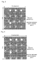
Fig. 3 is a diagramillustrating embodiment 1 of the method shown inFig. 2 ; -
Fig. 4 is a diagram illustrating embodiment 2 of the method shown inFig. 2 ; -
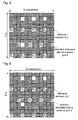
Fig. 5 is a diagram illustrating embodiment 3 of the method shown inFig. 2 ; -
Fig. 6 is a diagram illustrating embodiment 4 of the method shown inFig. 2 ; -
Fig. 7 is a diagramillustrating embodiment 5 of the method shown inFig. 2 ; -
Fig. 8 is a diagram illustrating embodiment 6 of the method shown inFig. 2 . - From
Fig. 3 to Fig. 8 ,denotes a downlink dedicated pilot; denotes a resource element.
- In the existing version of the LTE standard, when more than 4 antennas are adopted at the base station for beamforming, the cell-specific reference signals cannot acquire all channel information, and there is a problem of the feedback overhead of beamforming weight-values. Considering that downlink dedicated pilots of a beamforming are weigh-processed by multiple antennas, it is applicable to incorporate multiple transmitting antennas into one antenna port by way of a weigh-process upon the multiple antennas, namely channel information of all transmitting antennas can be estimated through only one port of downlink dedicated pilots, and the downlink dedicated pilots can estimate channel information that is weigh-processed by multiple antennas, so adopting downlink dedicated pilots is a scheme of low overhead and good performance.
- By clarifying the position of a pilot symbol in a physical resource block in the present invention, it is defined at which positions of the Extended CP frame structure in the LTE system should the downlink dedicated pilots be sent, and how the time-domain interval and frequency-domain interval are arranged, so that operation of downlink dedicated pilots in an LTE system is provided with a foundation, and the existing LTE version can support a beamforming with lower overhead and superior performance when applying the dedicated pilot design according to embodiments of the present invention. The above-mentioned Extended CP frame structure may be a resource block (RB) which comprises twelve subcarriers in the frequency domain, and twelve OFDM symbols in the time domain.
- In addition, the method for mapping downlink dedicated pilots to resource elements in a Normal Cyclic Prefix (Normal CP) frame structure was defined at the 52nd meeting of the LTE Standard, on this basis, according to the conclusion of the meeting, the present invention provides a method for mapping downlink dedicated pilots to resource elements in Extended CP frame structure, the method being of low overhead and having good performance.
- According to the method for mapping downlink dedicated pilots to resource elements in Normal CP frame structure defined at the 52nd meeting of LTE Standard, when downlink dedicated pilots of a beamforming are adopted, four ports cell-specific reference signals are inserted for all-around detection of control channels, and the mapping relation between the four ports cell-specific reference signals and the minimum physical resource block is shown in
Fig. 1. Fig. 1 shows the cell-specific reference signals and resource elements respectively transmitted by antenna ports 0 to 3. - Exemplary embodiments of the present invention will be described with reference to accompanying drawings hereinafter, and it should be understood that, the described exemplary embodiments are only used to describe and illustrate, rather than limit the present invention:
-
Fig. 2 is a flowchart illustrating the method of mapping downlink dedicated pilots to resource elements in Extended CP frame structure according to the present invention, which comprises the following steps:- step S202: frequency-domain interval configuration process - the frequency-domain interval of downlink dedicated pilots that are mapped to the same time domain is configured to be two subcarriers;
- step S204: time-domain interval configuration process - the time-domain interval of downlink dedicated pilots that are mapped to different time domains is configured to be two or three OFDM symbols;
- step S206: initial mapping process - the first downlink dedicated pilot is mapped to a specific position of a physical resource block, the specific position is also called the initial position which is represented by A and B, wherein, A is the frequency domain initial position, and B is the time domain initial position;
- step S208: mapping process for other downlink dedicated pilots of the port-the mapping process is carried out according to the initial position, frequency-domain interval and time-domain interval of the first downlink dedicated pilot and the preset regulation.
- The above-mentioned preset regulation is: twelve subcarriers are mapped to a physical resource block in the frequency domain, four downlink dedicated pilots of each port are mapped in the same time domain, and the downlink dedicated pilots are two subcarriers apart from each other. When there are multiple ports of downlink dedicated pilots, each port can be processed according to this method.
- The process of each step mentioned above will be described in detail hereinafter:
- Step S202: frequency-domain interval configuration process, which is also called frequency domain density configuration process.
- It is determined in the present invention that, downlink dedicated pilots of each beamforming at an RB are two subcarriers apart from each other; when multiple RBs are transmitted together, frequency-domain density of dedicated pilots are distributed evenly, wherein the interval is two subcarriers.
- The frequency-domain density of dedicated pilots is determined by coherent bandwidth, in order to avoid distortion of channel estimation, the lowest limit of pilot density is determined by a Nyquist sampling theorem. Because the frame structure of Extended CP is specially for the situation of large coverage, in which the frequency-selective fading of a channel becomes more serious, in order to further guarantee the performance of channel estimation, pilot symbols that are four times that adopted in the sampling theorem are adopted in the present invention, thus the frequency-domain interval of pilots Sf is as shown in formula (1):

in formula (1), Δf is a subcarrier interval, τmax is a maximum channel delay, which can be referred to in 3GPP TR25.996. Therefore, dedicated pilots intervals of two subcarriers in the frequency domain can completely meet the requirement of channel estimation. - Step 204: time domain-interval configuration process, which is also called time domain density configuration process.
- The time-domain density of pilot symbols is determined by coherent time, in order to avoid distortion of channel estimation, the lowest limit of pilot density is determined by the Nyquist sampling theorem. To further improve performance of channel estimation, pilot symbols that are four times that adopted in the sampling theorem are adopted in the present invention, thus the time-domain interval of pilots St is as shown in formula (2):

in formula (2), fd is a maximum Doppler frequency offset, it is regulated by LTE that the maximum moving speed of UE is 350km/h, herein, fd =648Hz. Tf is a time of OFDM symbol. Intervals between downlink dedicated pilots are two to three OFDM symbols, which can meet the requirement of channel estimation under high speed. - After the above-mentioned time-domain and frequency-domain intervals configuration processes, dedicated pilots are evenly distributed in both time domain and frequency domain, which can guarantee the quality of channel estimation.
- Step S206: initial mapping process;
- in this step, D is set to be the time domain initial position, while A is set to be: at the same position as the subcarrier where the first cell-specific reference signals of each OFDM symbol of the smallest physical resource block is located, namely, A is located at the same subcarrier as the first column of cell-specific reference signals of a resource block.
- Preferably, A=1 and D=5, namely, the mapped initial position of the first downlink dedicated pilot in the frequency domain is set to be the first subcarrier, while the mapped position in the time domain is the 5th OFDM symbol. This design of initial position of dedicated pilot is more reasonable than that raised previously in other methods for mapping dedicated pilots, with better performance under the same pilot overhead.
- The first row of downlink dedicated pilots of a beamforming starts from the first subcarrier in the frequency domain, start position of dedicated pilots and that of cell-specific reference signals are the same, beamforming weight-values are obtained by uplink or downlink cell-specific reference signals through estimating the real channels, so that pilots of adjacent positions will resume channel information more accurately.
- Start position of downlink dedicated pilots in the time domain is at the fifth OFDM symbol, so that the dedicated pilots are distributed evenly in a physical block, which can bring better channel estimating performance.
- Step S208, in this step, four downlink dedicated pilots are mapped in the same time domain.
- Frequency domain position of dedicated pilot is the same as that of the cell-specific reference signals, which is helpful to improve performance of channel estimation interpolation; and the consistency of channel information extraction and applied position during a beamforming procedure is guaranteed, which can reduce accumulated error.
- 1. According to the above-mentioned method, when there is one port of the downlink dedicated pilots corresponding to a single beam, the mapping method comprises:
- the corresponding position of the initial position in the time domain is at the 5th OFDM symbol, while the position in the frequency domain is set to be the same subcarrier of the first column of cell-specific reference signals in a physical resource block.
- The physical resource block comprises twelve subcarriers in the frequency domain, which are the 1st to 12th subcarriers, as well as twelve OFDM symbols in the time domain, which are the 1st to the 12th OFDM symbols.
- One port of twelve downlink dedicated pilots are divided into four groups in this mapping method, and each group comprises 4 downlink dedicated pilots that are located at the same OFDM symbol.
- in the time domain, the first group of downlink dedicated pilots is mapped to the 5th OFDM symbol in the time domain, the second group of downlink dedicated pilots is mapped to the 8th OFDM symbol in the time domain, and the third group of downlink dedicated pilots is mapped to the 11th or 12th OFDM symbol in the time domain; or, the first group of downlink dedicated pilots is mapped to the 5th OFDM symbol in the time domain, the second group of downlink dedicated pilots is mapped to the 9th OFDM symbol in the time domain, and the third group of downlink dedicated pilots is mapped to the 12th OFDM symbol in the time domain.
- in the frequency domain, the 1st one of four downlink dedicated pilots in one group is mapped to the 1st, 2nd or 3rd subcarrier in the frequency domain, while the 2nd to 4th downlink dedicated pilots are mapped to subcarriers that are two subcarriers apart from each other in order in the frequency domain.
- Specifically:
- the first downlink dedicated pilot is mapped to the 5th OFDM symbol in the time domain, while to the Ath subcarrier in the frequency domain; the second downlink dedicated pilot is mapped to the 5th OFDM symbol in the time domain, while to the (A+3)th subcarrier in the frequency domain; the third downlink dedicated pilot is mapped to the 5th OFDM symbol in the time domain, while to the (A+6)th subcarrier in the frequency domain; the fourth downlink dedicated pilot is mapped to the 5th OFDM symbol in the time domain, while to the (A+g)th subcarrier in the frequency domain, wherein A=1, 2 or 3;
- the fifth downlink dedicated pilot is mapped to the 8th OFDM symbol in the time domain, while to the Bth subcarrier in the frequency domain; the sixth downlink dedicated pilot is mapped to the 8th OFDM symbol in the time domain, while to the (B+3)th subcarrier in the frequency domain; the seventh downlink dedicated pilot is mapped to the 8th OFDM symbol in the time domain, while to the (B+6)th subcarrier in the frequency domain; the eighth downlink dedicated pilot is mapped to the 8th OFDM symbol in the time domain, while to the (B+9)th subcarrier in the frequency domain, wherein B=1, 2 or 3;
- the ninth downlink dedicated pilot is mapped to the 11th or 12th OFDM symbol in the time domain, while to the Cth subcarrier in the frequency domain; the tenth downlink dedicated pilot is mapped to the 11th or 12th OFDM symbol in the time domain, while to the (C+3)th subcarrier in the frequency domain; the eleventh downlink dedicated pilot is mapped to the 11th or 12th OFDM symbol in the time domain, while to the (C+6)th subcarrier in the frequency domain; the eighth downlink dedicated pilot is mapped to the 11th or 12th OFDM symbol in the time domain, while to the (C+g)th subcarrier in the frequency domain, wherein C=1, 2 or 3.
- A, B and C can be chosen from 1 to 3.
- In addition, the fifth, sixth, seventh and eighth downlink dedicated pilots can also be mapped to the 9th OFDM symbol in the time domain, and mapping in the frequency domain is the same as above. Accordingly, the ninth, tenth, eleventh and twelfth downlink dedicated pilots are mapped to the 12th OFDM symbol in the time domain, and mapping in the frequency domain is the same as above.
- The above-mentioned downlink dedicated pilots should be configured in a manner which avoids the cell-specific reference signals.
- 2. There are multiple ports of downlink dedicated pilots (generally no more than 3 ports), corresponding to multiple beams;
- corresponding positions in the time domain of all ports' initial positions are same, located at the 5th OFDM symbol, while corresponding positions in the frequency domain are staggered (frequency-domain position of the first port's initial position can be set to the same subcarrier as that of the first column of cell-specific reference signals in a physical resource block, while initial positions of other ports are staggered with that of the first).
- According to the above steps and design principle, method of the present invention will be further illustrated in detail with reference to some embodiments hereinafter:
- Embodiment 1:
- as shown in
Fig. 3 , since A=1 and D=5, in this embodiment of the present invention, downlink dedicated pilots are mapped to the 5th, 8th and 11th OFDM symbols respectively in the time domain.
On such a basis, the operation in step S208 of mapping other downlink dedicated pilots is specifically:- the second downlink dedicated pilot is mapped to the 5th OFDM symbol in the time domain, while to the (A+3=4)th subcarrier in the frequency domain;
- the third downlink dedicated pilot is mapped to the 5th OFDM symbol in the time domain, while to the (A+6=7)th subcarrier in the frequency domain;
- the fourth downlink dedicated pilot is mapped to the 5th OFDM symbol in the time domain, while to the (A+9=10)th subcarrier in the frequency domain;
- the fifth downlink dedicated pilot is mapped to the 8th OFDM symbol in the time domain, while to the (B=3)th subcarrier in the frequency domain;
- the sixth downlink dedicated pilot is mapped to the 8th OFDM symbol in the time domain, while to the (B+3=6)th subcarrier in the frequency domain;
- the seventh downlink dedicated pilot is mapped to the 8th OFDM symbol in the time domain, while to the (B+6=9)th subcarrier in the frequency domain;
- the eighth downlink dedicated pilot is mapped to the 8th OFDM symbol in the time domain, while to the (B+9=12)th subcarrier in the frequency domain;
- the ninth downlink dedicated pilot is mapped to the 11th OFDM symbol in the time domain, while to the (C=1)th subcarrier in the frequency domain;
- the tenth downlink dedicated pilot is mapped to the 11th OFDM symbol in the time domain, while to the (C+3=4)th subcarrier in the frequency domain;
- the eleventh downlink dedicated pilot is mapped to the 11th OFDM symbol in the time domain, while to the (C+6=7)th subcarrier in the frequency domain;
- the twelfth downlink dedicated pilot is mapped to the 11th OFDM symbol in the time domain, while to the (C+9=10)thsubcarrier in the frequency domain.
- as shown in
- Embodiment 2:
- as shown in
Fig. 4 , since A=1 and B=5, in this embodiment of the present invention, downlink dedicated pilots are mapped to the 5th, 8th and 12th OFDM symbols respectively in the time domain.
On such a basis, the operation in step S208 of mapping other downlink dedicated pilots is specifically:- the second downlink dedicated pilot is mapped to the 5th OFDM symbol in the time domain, while to the (A+3=4)th subcarrier in the frequency domain;
- the third downlink dedicated pilot is mapped to the 5th OFDM symbol in the time domain, while to the (A+6=7)thsubcarrier in the frequency domain;
- the fourth downlink dedicated pilot is mapped to the 5th OFDM symbol in the time domain, while to the (A+9=10)th subcarrier in the frequency domain;
- the fifth downlink dedicated pilot is mapped to the 8th OFDM symbol in the time domain, while to the (A=1)th subcarrier in the frequency domain;
- the sixth downlink dedicated pilot is mapped to the 8th OFDM symbol in the time domain, while to the (A+3=4)th subcarrier in the frequency domain;
- the seventh downlink dedicated pilot is mapped to the 8th OFDM symbol in the time domain, while to the (A+6=7)th subcarrier in the frequency domain;
- the eighth downlink dedicated pilot is mapped to the 8th OFDM symbol in the time domain, while to the (A+9=10)th subcarrier in the frequency domain;
- the ninth downlink dedicated pilot is mapped to the 12th OFDM symbol in the time domain, while to the (A=1)th subcarrier in the frequency domain;
- the tenth downlink dedicated pilot is mapped to the 12th OFDM symbol in the time domain, while to the (A+3=4)th subcarrier in the frequency domain;
- the eleventh downlink dedicated pilot is mapped to the 12th OFDM symbol in the time domain, while to the (A+6=7)th subcarrier in the frequency domain;
- the twelfth downlink dedicated pilot is mapped to the 12th OFDM symbol in the time domain, while to the (A+9=10)th subcarrier in the frequency domain.
- as shown in
- Embodiment 3:
- as shown in
Fig. 5 , since A=1 and D=5, in this embodiment of the present invention, downlink dedicated pilots are mapped to the 5th, 9th and 12th OFDM symbols respectively in the time domain.
On such a basis, the operation in step S208 of mapping other downlink dedicated pilots is specifically:- the second downlink dedicated pilot is mapped to the 5th OFDM symbol in the time domain, while to the (A+3=4)th subcarrier in the frequency domain;
- the third downlink dedicated pilot is mapped to the 5th OFDM symbol in the time domain, while to the (A+6=7)th subcarrier in the frequency domain;
- the fourth downlink dedicated pilot is mapped to the 5th OFDM symbol in the time domain, while to the (A+9=10)th subcarrier in the frequency domain;
- the fifth downlink dedicated pilot is mapped to the 9th OFDM symbol in the time domain, while to the (B=3)th subcarrier in the frequency domain;
- the sixth downlink dedicated pilot is mapped to the 9th OFDM symbol in the time domain, while to the (B+3=6)th subcarrier in the frequency domain;
- the seventh downlink dedicated pilot is mapped to the 9th OFDM symbol in the time domain, while to the (B+6=9)th subcarrier in the frequency domain;
- the eighth downlink dedicated pilot is mapped to the 9th OFDM symbol in the time domain, while to the (B+9=12)th subcarrier in the frequency domain;
- the ninth downlink dedicated pilot is mapped to the 12th OFDM symbol in the time domain, while to the (C=1)th subcarrier in the frequency domain;
- the tenth downlink dedicated pilot is mapped to the 12th OFDM symbol in the time domain, while to the (C+3=4)th subcarrier in the frequency domain;
- the eleventh downlink dedicated pilot is mapped to the 12th OFDM symbol in the time domain, while to the (C+6=7)th subcarrier in the frequency domain;
- the twelfth downlink dedicated pilot is mapped to the 12th OFDM symbol in the time domain, while to the (C+9=10)th subcarrier in the frequency domain.
- as shown in
- Embodiment 4:
- as shown in
Fig. 6 , since A=1 and D=5, in this embodiment of the present invention, downlink dedicated pilots are mapped to the 5th, 8th and 12th OFDM symbols respectively in the time domain.
On such a basis, the operation in step S208 of mapping other downlink dedicated pilots is specifically:- the second downlink dedicated pilot is mapped to the 5th OFDM symbol in the time domain, while to the (A+3=4)th subcarrier in the frequency domain;
- the third downlink dedicated pilot is mapped to the 5th OFDM symbol in the time domain, while to the (A+6=7)th subcarrier in the frequency domain;
- the fourth downlink dedicated pilot is mapped to the 5th OFDM symbol in the time domain, while to the (A+9=10)th subcarrier in the frequency domain;
- the fifth downlink dedicated pilot is mapped to the 8th OFDM symbol in the time domain, while to the (B=3)th subcarrier in the frequency domain;
- the sixth downlink dedicated pilot is mapped to the 8th OFDM symbol in the time domain, while to the (B+3=6)th subcarrier in the frequency domain;
- the seventh downlink dedicated pilot is mapped to the 8th OFDM symbol in the time domain, while to the (B+6=9)th subcarrier in the frequency domain;
- the eighth downlink dedicated pilot is mapped to the 8th OFDM symbol in the time domain, while to the (B+9=12)th subcarrier in the frequency domain;
- the ninth downlink dedicated pilot is mapped to the 12th OFDM symbol in the time domain, while to the (C=1)th subcarrier in the frequency domain;
- the tenth downlink dedicated pilot is mapped to the 12th OFDM symbol in the time domain, while to the (C+3=4)th subcarrier in the frequency domain;
- the eleventh downlink dedicated pilot is mapped to the 12th OFDM symbol in the time domain, while to the (C+6=7)th subcarrier in the frequency domain;
- the twelfth downlink dedicated pilot is mapped to the 12th OFDM symbol in the time domain, while to the (C+9=10)th subcarrier in the frequency domain.
- as shown in
- Embodiment 5:
- as shown in
Fig. 7 , since A=1 and D=5, in this embodiment of the present invention, downlink dedicated pilots are mapped to the 5th, 8th and 11th OFDM symbols respectively in the time domain.
On such a basis, the operation in step S208 of mapping other downlink dedicated pilots is specifically:- the second downlink dedicated pilot is mapped to the 5th OFDM symbol in the time domain, while to the (A+3=4)th subcarrier in the frequency domain;
- the third downlink dedicated pilot is mapped to the 5th OFDM symbol in the time domain, while to the (A+6=7)th subcarrier in the frequency domain;
- the fourth downlink dedicated pilot is mapped to the 5th OFDM symbol in the time domain, while to the (A+9=10)th subcarrier in the frequency domain;
- the fifth downlink dedicated pilot is mapped to the 8th OFDM symbol in the time domain, while to the (B=2)th subcarrier in the frequency domain;
- the sixth downlink dedicated pilot is mapped to the 8th OFDM symbol in the time domain, while to the (B+3=5)th subcarrier in the frequency domain;
- the seventh downlink dedicated pilot is mapped to the 8th OFDM symbol in the time domain, while to the (B+6=8)th subcarrier in the frequency domain;
- the eighth downlink dedicated pilot is mapped to the 8th OFDM symbol in the time domain, while to the (B+9=11)th subcarrier in the frequency domain;
- the ninth downlink dedicated pilot is mapped to the 11th OFDM symbol in the time domain, while to the (C=3)th subcarrier in the frequency domain;
- the tenth downlink dedicated pilot is mapped to the 11th OFDM symbol in the time domain, while to the (C+3=6)th subcarrier in the frequency domain;
- the eleventh downlink dedicated pilot is mapped to the 11th OFDM symbol in the time domain, while to the (C+6=9)th subcarrier in the frequency domain;
- the twelfth downlink dedicated pilot is mapped to the 11th OFDM symbol in the time domain, while to the (C+9=12)th subcarrier in the frequency domain.
- as shown in
- Embodiment 6:
- as shown in
Fig. 8 , since A=1 and D=5, in this embodiment of the present invention, downlink dedicated pilots are mapped to the 5th 8th and 11th OFDM symbols respectively in the time domain.
On such a basis, the operation in step S208 of mapping other downlink dedicated pilots is specifically:- the second downlink dedicated pilot is mapped to the 5th OFDM symbol in the time domain, and to the (A+3=4)th subcarrier in the frequency domain;
- the third downlink dedicated pilot is mapped to the 5th OFDM symbol in the time domain, while to the (A+6=7)th subcarrier in the frequency domain;
- the fourth downlink dedicated pilot is mapped to the 5th OFDM symbol in the time domain, while to the (A+9=10)th subcarrier in the frequency domain;
- the fifth downlink dedicated pilot is mapped to the 8th OFDM symbol in the time domain, while to the (B=1)th subcarrier in the frequency domain;
- the sixth downlink dedicated pilot is mapped to the 8th OFDM symbol in the time domain, while to the (B+3=4)th subcarrier in the frequency domain;
- the seventh downlink dedicated pilot is mapped to the 8th OFDM symbol in the time domain, while to the (B+6=7)th subcarrier in the frequency domain;
- the eighth downlink dedicated pilot is mapped to the 8th OFDM symbol in the time domain, while to the (B+9=10)th subcarrier in the frequency domain;
- the ninth downlink dedicated pilot is mapped to the 11th OFDM symbol in the time domain, while to the (C=1)th subcarrier in the frequency domain;
- the tenth downlink dedicated pilot is mapped to the 11th OFDM symbol in the time domain, while to the (C+3=4)th subcarrier in the frequency domain;
- the eleventh downlink dedicated pilot is mapped to the 11th OFDM symbol in the time domain, while to the (C+6=7)th subcarrier in the frequency domain;
- the twelfth downlink dedicated pilot is mapped to the 11th OFDM symbol in the time domain, while to the (C+9=10)th subcarrier in the frequency domain.
- as shown in
- It can be seen from the above description that, in the present invention, by presetting the frequency-domain interval and time-domain interval, and by determining the position of the first downlink dedicated pilot (start position in the frequency domain and start position in the time domain), and according to the preset regulation, the position of a pilot symbol in a physical resource block can be determined.
- The downlink dedicated pilot structure supports any number of antennas as well as a single layer beamforming of antenna spacing. Downlink dedicated pilots are distinguished by beams, and the present invention concerns itself with a single-beamforming, so the dedicated pilot structure provided by embodiments of the present invention comprises only one port of dedicated pilots, as to those skilled in the art, the situation of multiple beams can be deduced according to relevant pilot density, for example, two ports of dedicated pilots are adopted in two beams, and the rest can be done in the same manner.
- The present invention is not limited to the above described exemplary embodiments. For those skilled in the art, various modifications and changes can be made to the present invention. Any modification, equivalent substitute and improvement within the spirit of the present invention is deemed to be included within the scope of the present invention, as defined by the claims.
Claims (11)
- A method for mapping downlink dedicated pilots to resource elements in Extended Cyclic Prefix (Extended CP) frame structure, applied in a Long Term Evolution (LTE) system, comprising the following steps:mapping the first downlink dedicated pilot of each port to the specific position of a physical resource block;mapping-processing other downlink dedicated pilots of the port according to the time-domain interval, frequency-domain interval and the preset regulation; andthe time-domain interval being two or three Orthogonal Frequency Division Multiplexing symbols, and the frequency-domain interval being two subcarriers in the same time domain.
- The mapping method according to claim 1, wherein, the preset regulation is: 12 subcarriers are mapped to the physical resource blocks in the frequency domain, while one port of four downlink dedicated pilots is mapped in the same time domain, and the dedicated pilots are two subcarriers apart from each other.
- The mapping method according to claim 1 or claim 2, wherein, only one port of downlink dedicated pilots is transmitted in the physical resource block.
- The mapping method according to claim 3, wherein, the corresponding time-domain position of the specific position is the 5th orthogonal frequency division multiplexing symbol, and the corresponding frequency-domain position thereof is the same subcarrier of the first column of cell-specific reference signals in the physical resource block.
- The mapping method according to claim 3, wherein, the physical resource block comprises twelve subcarriers in the frequency domain, and twelve orthogonal frequency division multiplexing symbols in the time domain, the mapping method comprises specifically:mapping the first downlink dedicated pilot to the 5th orthogonal frequency division multiplexing symbol in the time domain, and to the Ath subcarrier in the frequency domain; mapping the second downlink dedicated pilot to the 5th orthogonal frequency division multiplexing symbol in the time domain, and to the (A+3)th subcarrier in the frequency domain; mapping the third downlink dedicated pilot to the 5th orthogonal frequency division multiplexing symbol in the time domain, and to the (A+6)th subcarrier in the frequency domain; mapping the fourth downlink dedicated pilot to the 5th orthogonal frequency division multiplexing symbol in the time domain, and to the (A+g)th subcarrier in the frequency domain;mapping the fifth downlink dedicated pilot to the 8th orthogonal frequency division multiplexing symbol in the time domain, and to the Bth subcarrier in the frequency domain; mapping the sixth downlink dedicated pilot to the 8th orthogonal frequency division multiplexing symbol in the time domain, and to the (B+3)th subcarrier in the frequency domain; mapping the seventh downlink dedicated pilot to the 8th orthogonal frequency division multiplexing symbol in the time domain, and to the (B+6)th subcarrier in the frequency domain; mapping the eighth downlink dedicated pilot to the 8th orthogonal frequency division multiplexing symbol in the time domain, and to the (B+9)th subcarrier in the frequency domain;mapping the ninth downlink dedicated pilot to the 12th orthogonal frequency division multiplexing symbol in the time domain, and to the Cth subcarrier in the frequency domain; mapping the tenth downlink dedicated pilot to the 12th orthogonal frequency division multiplexing symbol in the time domain, and to the (C+3)th subcarrier in the frequency domain; mapping the eleventh downlink dedicated pilot to the 12th orthogonal frequency division multiplexing symbol in the time domain, and to the (C+6)th subcarrier in the frequency domain; mapping the eighth downlink dedicated pilot to the 12th orthogonal frequency division multiplexing symbol in the time domain, and to the (C+9)th subcarrier in the frequency domain;
wherein, B and C equal to 1 or 2 or 3. - The mapping method according to claim 1 or claim 2, wherein, there are multiple ports of downlink dedicated pilots in the physical resource block, and the specific time-domain positions to which each port of downlink dedicated pilots is mapped in the physical resource block are located at the 5th orthogonal frequency division multiplexing symbol of the physical resource block, while the specific frequency-domain positions to which every port of downlink dedicated pilots is mapped in a physical resource block being staggered from one another.
- The mapping method according to claim 3, wherein, the physical resource block comprises twelve subcarriers in the frequency domain, and twelve orthogonal frequency division multiplexing symbols in the time domain, and the mapping method comprises specifically:dividing a port of twelve downlink dedicated pilots into four groups, each group comprising four downlink dedicated pilots that are located at the same orthogonal frequency division multiplexing symbol;in the time domain, mapping the first group of downlink dedicated pilots to the 5th orthogonal frequency division multiplexing symbol in the time domain; mapping the second group of downlink dedicated pilots to the 8th orthogonal frequency division multiplexing symbol in the time domain; and mapping the third group of downlink dedicated pilots to the 11th or 12th orthogonal frequency division multiplexing symbol in the time domain;in the frequency domain, mapping the 1st one of 4 downlink dedicated pilots in each group to the 1st or 2nd or 3rd subcarrier in the frequency domain, and mapping the 2nd to 4th downlink dedicated pilots to subcarriers that are two subcarriers apart from each other in order in the frequency domain.
- The mapping method according to claim 3, wherein, the physical resource block comprises twelve subcarriers in the frequency domain, and twelve orthogonal frequency division multiplexing symbols in the time domain, and the mapping method comprises specifically:dividing a port of twelve downlink dedicated pilots into four groups, each group comprising four downlink dedicated pilots that are located at the same orthogonal frequency division multiplexing symbol;in the time domain, mapping the first group of downlink dedicated pilots to the 5th orthogonal frequency division multiplexing symbol in the time domain; mapping the second group of downlink dedicated pilots to the 9th orthogonal frequency division multiplexing symbol in the time domain; and mapping the third group of downlink dedicated pilots to the 12th orthogonal frequency division multiplexing symbol in the time domain;in the frequency domain, mapping the 1st one of four downlink dedicated pilots in each group to the 1st, 2nd or 3rd subcarrier in the frequency domain, and mapping the 2nd to 4th downlink dedicated pilots to subcarriers that are two subcarriers apart from each other in order in the frequency domain.
- The mapping method according to claim 7, wherein:the 1st, 2nd, 3rd, 4th downlink dedicated pilots are all mapped to the 5th OFDM symbol in the time domain, and to the 1st, 4th 7th, 10th subcarriers sequentially in the frequency domain;the 5th, 6th, 7th, 8th downlink dedicated pilots are all mapped to the 8th OFDM symbol in the time domain, and to the 1st, 4th 7th, 10th subcarriers sequentially in the frequency domain, or to the 3rd, 6th, 9th, 12th subcarriers sequentially in the frequency domain;the 9th, 10th, 11th, 12th downlink dedicated pilots are all mapped to the 11th or 12th OFDM symbol in the time domain, and to the 1st, 4th, 7th, 10th subcarriers sequentially in the frequency domain.
- The mapping method according to claim 7, wherein:the 1st, 2nd, 3rd, 4th downlink dedicated pilots are all mapped to the 5th OFDM symbol in the time domain, and to the 1st, 4th 7th, 10th subcarriers sequentially in the frequency domain;the 5th 6th, 7th, 8th downlink dedicated pilots are all mapped to the 8th OFDM symbol in the time domain, and to the 2nd, 5th, 8th, 11th subcarriers sequentially in the frequency domain;the 9th, 10th, 11th, 12th downlink dedicated pilots are all mapped to the 11th or 12th OFDM symbol in the time domain, and to the 3rd, 6th, 9th, 12th subcarriers sequentially in the frequency domain.
- The mapping method according to claim 8, wherein:the 1st, 2nd, 3rd, 4th downlink dedicated pilots are all mapped to the 5th OFDM symbol in the time domain, and to the 1st, 4th, 7th, 10th subcarriers sequentially in the frequency domain;the 5th 6th, 7th, 8th downlink dedicated pilots are all mapped to the 9th OFDM symbol in the time domain, and to the 3rd, 6th, 9th, 12th subcarriers sequentially in the frequency domain;the 9th, 10th, 11th, 12th downlink dedicated pilots are all mapped to the 12th OFDM symbol in the time domain, and to the 1st, 4th, 7th, 10th subcarriers sequentially in the frequency domain.
Applications Claiming Priority (2)
| Application Number | Priority Date | Filing Date | Title |
|---|---|---|---|
| CN200810085767A CN101350801B (en) | 2008-03-20 | 2008-03-20 | Method for mapping down special pilot frequency and physical resource block of long loop prefix frame structure |
| PCT/CN2008/073714 WO2009114983A1 (en) | 2008-03-20 | 2008-12-25 | Method for mapping downlink dedicated pilot frequencies of extend cyclic prefix frame structure to physical resource blocks |
Publications (2)
| Publication Number | Publication Date |
|---|---|
| EP2164181A1 true EP2164181A1 (en) | 2010-03-17 |
| EP2164181A4 EP2164181A4 (en) | 2014-01-15 |
Family
ID=40269381
Family Applications (1)
| Application Number | Title | Priority Date | Filing Date |
|---|---|---|---|
| EP20080873412 Ceased EP2164181A4 (en) | 2008-03-20 | 2008-12-25 | Method for mapping downlink dedicated pilot frequencies of extend cyclic prefix frame structure to physical resource blocks |
Country Status (6)
| Country | Link |
|---|---|
| US (1) | US8391233B2 (en) |
| EP (1) | EP2164181A4 (en) |
| JP (1) | JP5208219B2 (en) |
| KR (1) | KR101140044B1 (en) |
| CN (1) | CN101350801B (en) |
| WO (1) | WO2009114983A1 (en) |
Cited By (1)
| Publication number | Priority date | Publication date | Assignee | Title |
|---|---|---|---|---|
| US20220209837A1 (en) * | 2011-07-28 | 2022-06-30 | Samsung Electronics Co., Ltd. | Apparatus and method for beamforming in wireless communication system |
Families Citing this family (92)
| Publication number | Priority date | Publication date | Assignee | Title |
|---|---|---|---|---|
| JP5684581B2 (en) | 2008-03-13 | 2015-03-11 | アイディーティーピー ホールディングス インコーポレイテッド | Neighboring cell quality measurement in communication systems |
| US8259825B2 (en) * | 2008-08-08 | 2012-09-04 | Motorola Mobility, Inc. | Mapping and signaling of common reference symbols for multiple antennas |
| CN101815047B (en) * | 2009-02-25 | 2013-12-04 | 中兴通讯股份有限公司 | Method and device for mapping demodulation pilots and physical resource block |
| CN101834820A (en) * | 2009-03-09 | 2010-09-15 | 中兴通讯股份有限公司 | Resource mapping method of demodulation pilot frequency |
| CA2755574C (en) | 2009-03-16 | 2017-09-12 | Rockstar Bidco, LP | Transmission using common and dedicated pilots |
| CN101510868A (en) * | 2009-03-17 | 2009-08-19 | 中兴通讯股份有限公司 | Mapping method of reference signal and physical resource block |
| CN105791200A (en) * | 2009-03-17 | 2016-07-20 | 中兴通讯股份有限公司 | Mapping method of reference signal and physical resource block |
| CN101841817B (en) * | 2009-03-20 | 2013-09-11 | 中兴通讯股份有限公司 | Method for configuring signal channel measurement pilot frequency |
| US11218194B2 (en) | 2009-03-23 | 2022-01-04 | Lg Electronics Inc. | Method and apparatus for transmitting reference signal in multi-antenna system |
| CN102362443B (en) | 2009-03-23 | 2015-10-07 | Lg电子株式会社 | Method and device for transmitting a reference signal in a multi-antenna system |
| CN101867949B (en) * | 2009-04-20 | 2015-05-20 | 中兴通讯股份有限公司 | Mapping method of channel measurement pilot frequency and physical resource block |
| CN101594335B (en) * | 2009-06-19 | 2017-02-08 | 中兴通讯股份有限公司 | Mapping method for reference signals and physical resource block |
| US9049157B1 (en) | 2009-08-16 | 2015-06-02 | Compass Electro-Optical Systems Ltd | Method and device for improving scalability of longest prefix match |
| CN102014096B (en) * | 2009-09-04 | 2014-06-11 | 中兴通讯股份有限公司 | Device and method for mapping demodulated pilot frequency |
| CN102055517A (en) * | 2009-11-02 | 2011-05-11 | 中兴通讯股份有限公司 | Mapping method of reference signal and base station adopted in mapping method |
| CN101719888B (en) * | 2009-11-10 | 2013-03-20 | 中兴通讯股份有限公司 | System and method for mapping reference signal sequence in long term evolution-advanced (LTE-A) system |
| CN102118868B (en) * | 2009-12-31 | 2015-10-21 | 中兴通讯股份有限公司 | Cell resources in cooperative measurement set during multipoint cooperative transmission mapping method and system |
| US10667148B1 (en) | 2010-05-28 | 2020-05-26 | Cohere Technologies, Inc. | Methods of operating and implementing wireless communications systems |
| US9071286B2 (en) | 2011-05-26 | 2015-06-30 | Cohere Technologies, Inc. | Modulation and equalization in an orthonormal time-frequency shifting communications system |
| US9444514B2 (en) | 2010-05-28 | 2016-09-13 | Cohere Technologies, Inc. | OTFS methods of data channel characterization and uses thereof |
| US8976851B2 (en) | 2011-05-26 | 2015-03-10 | Cohere Technologies, Inc. | Modulation and equalization in an orthonormal time-frequency shifting communications system |
| US9071285B2 (en) | 2011-05-26 | 2015-06-30 | Cohere Technologies, Inc. | Modulation and equalization in an orthonormal time-frequency shifting communications system |
| US10681568B1 (en) | 2010-05-28 | 2020-06-09 | Cohere Technologies, Inc. | Methods of data channel characterization and uses thereof |
| US11943089B2 (en) | 2010-05-28 | 2024-03-26 | Cohere Technologies, Inc. | Modulation and equalization in an orthonormal time-shifting communications system |
| US9130638B2 (en) | 2011-05-26 | 2015-09-08 | Cohere Technologies, Inc. | Modulation and equalization in an orthonormal time-frequency shifting communications system |
| MX2012014098A (en) * | 2010-06-01 | 2013-08-27 | Zte Corp | Methods and systems for csi-rs resource allocation in lte-advance systems. |
| CN102271109B (en) * | 2010-06-07 | 2015-08-12 | 中兴通讯股份有限公司 | A kind of mapping method of demodulation reference mark and system |
| US9252991B2 (en) * | 2010-08-10 | 2016-02-02 | Marvell World Trade Ltd. | Sub-band feedback for beamforming on downlink multiple user MIMO configurations |
| US9031141B2 (en) | 2011-05-26 | 2015-05-12 | Cohere Technologies, Inc. | Modulation and equalization in an orthonormal time-frequency shifting communications system |
| CN103248599B (en) * | 2012-02-06 | 2015-11-11 | 京信通信系统(中国)有限公司 | A kind of physical resource mapping method of Physical Downlink Shared Channel and device |
| US10411843B2 (en) | 2012-06-25 | 2019-09-10 | Cohere Technologies, Inc. | Orthogonal time frequency space communication system compatible with OFDM |
| US10469215B2 (en) | 2012-06-25 | 2019-11-05 | Cohere Technologies, Inc. | Orthogonal time frequency space modulation system for the Internet of Things |
| US10003487B2 (en) | 2013-03-15 | 2018-06-19 | Cohere Technologies, Inc. | Symplectic orthogonal time frequency space modulation system |
| US9967758B2 (en) | 2012-06-25 | 2018-05-08 | Cohere Technologies, Inc. | Multiple access in an orthogonal time frequency space communication system |
| US9912507B2 (en) | 2012-06-25 | 2018-03-06 | Cohere Technologies, Inc. | Orthogonal time frequency space communication system compatible with OFDM |
| US9929783B2 (en) | 2012-06-25 | 2018-03-27 | Cohere Technologies, Inc. | Orthogonal time frequency space modulation system |
| US10090972B2 (en) | 2012-06-25 | 2018-10-02 | Cohere Technologies, Inc. | System and method for two-dimensional equalization in an orthogonal time frequency space communication system |
| CN104982073B (en) * | 2013-01-14 | 2020-01-31 | Lg 电子株式会社 | Method for detecting small cell based on discovery signal |
| CN104639486B (en) * | 2013-11-12 | 2018-04-10 | 华为技术有限公司 | Transmission method and device |
| CN105491665B (en) | 2014-09-15 | 2019-07-23 | 中兴通讯股份有限公司 | Pilot frequency configuration method and device |
| CN107925434B (en) | 2015-05-11 | 2021-02-05 | 凝聚技术公司 | System and method for simorthogonal time-frequency shift modulation and transmission of data |
| US10090973B2 (en) | 2015-05-11 | 2018-10-02 | Cohere Technologies, Inc. | Multiple access in an orthogonal time frequency space communication system |
| US9866363B2 (en) | 2015-06-18 | 2018-01-09 | Cohere Technologies, Inc. | System and method for coordinated management of network access points |
| US10574317B2 (en) | 2015-06-18 | 2020-02-25 | Cohere Technologies, Inc. | System and method for providing wireless communication services using configurable broadband infrastructure shared among multiple network operators |
| US10404514B2 (en) | 2015-06-27 | 2019-09-03 | Cohere Technologies, Inc. | Orthogonal time frequency space communication system compatible with OFDM |
| US10892547B2 (en) | 2015-07-07 | 2021-01-12 | Cohere Technologies, Inc. | Inconspicuous multi-directional antenna system configured for multiple polarization modes |
| US10693581B2 (en) | 2015-07-12 | 2020-06-23 | Cohere Technologies, Inc. | Orthogonal time frequency space modulation over a plurality of narrow band subcarriers |
| CN108770382B (en) | 2015-09-07 | 2022-01-14 | 凝聚技术公司 | Multiple access method using orthogonal time frequency space modulation |
| WO2017049303A1 (en) * | 2015-09-17 | 2017-03-23 | Cohere Technologies, Inc. | Compatible use of orthogonal time frequency space modulation within an lte communication system |
| US11038733B2 (en) | 2015-11-18 | 2021-06-15 | Cohere Technologies, Inc. | Orthogonal time frequency space modulation techniques |
| WO2017100666A1 (en) | 2015-12-09 | 2017-06-15 | Cohere Technologies | Pilot packing using complex orthogonal functions |
| US10666314B2 (en) | 2016-02-25 | 2020-05-26 | Cohere Technologies, Inc. | Reference signal packing for wireless communications |
| WO2017165697A1 (en) | 2016-03-23 | 2017-09-28 | Cohere Technologies | Receiver-side processing of orthogonal time frequency space modulated signals |
| US9667307B1 (en) | 2016-03-31 | 2017-05-30 | Cohere Technologies | Wireless telecommunications system for high-mobility applications |
| WO2017173160A1 (en) | 2016-03-31 | 2017-10-05 | Cohere Technologies | Channel acquisition using orthogonal time frequency space modulated pilot signal |
| CN113726700B (en) | 2016-04-01 | 2024-09-24 | 凝聚技术公司 | Wireless communication method and apparatus for recovering information bits from a received signal by performing iterative equalization |
| US10063295B2 (en) | 2016-04-01 | 2018-08-28 | Cohere Technologies, Inc. | Tomlinson-Harashima precoding in an OTFS communication system |
| US10938602B2 (en) | 2016-05-20 | 2021-03-02 | Cohere Technologies, Inc. | Iterative channel estimation and equalization with superimposed reference signals |
| EP3497907A4 (en) | 2016-08-12 | 2020-03-04 | Cohere Technologies, Inc. | LOCALIZED EQUALIZATION FOR CHANNELS WITH INTERMEDIATE INTERFERENCE INTERFERENCES |
| WO2018031952A1 (en) | 2016-08-12 | 2018-02-15 | Cohere Technologies | Iterative multi-level equalization and decoding |
| EP3497785B1 (en) | 2016-08-12 | 2024-03-13 | Cohere Technologies, Inc. | Method for multi-user multiplexing of orthogonal time frequency space signals |
| WO2018064587A1 (en) | 2016-09-29 | 2018-04-05 | Cohere Technologies | Transport block segmentation for multi-level codes |
| US10965348B2 (en) | 2016-09-30 | 2021-03-30 | Cohere Technologies, Inc. | Uplink user resource allocation for orthogonal time frequency space modulation |
| CN107994936B (en) * | 2016-10-27 | 2021-03-16 | 中国移动通信有限公司研究院 | Downlink beam processing method and device |
| WO2018106731A1 (en) | 2016-12-05 | 2018-06-14 | Cohere Technologies | Fixed wireless access using orthogonal time frequency space modulation |
| EP3566379B1 (en) | 2017-01-09 | 2024-12-11 | Cohere Technologies, Inc. | Pilot scrambling for channel estimation |
| US10356632B2 (en) | 2017-01-27 | 2019-07-16 | Cohere Technologies, Inc. | Variable beamwidth multiband antenna |
| CN108631902B (en) * | 2017-03-24 | 2024-06-11 | 中兴通讯股份有限公司 | A configuration method and device |
| US10568143B2 (en) | 2017-03-28 | 2020-02-18 | Cohere Technologies, Inc. | Windowed sequence for random access method and apparatus |
| WO2018191309A1 (en) | 2017-04-11 | 2018-10-18 | Cohere Technologies | Digital communication using dispersed orthogonal time frequency space modulated signals |
| WO2018195548A1 (en) | 2017-04-21 | 2018-10-25 | Cohere Technologies | Communication techniques using quasi-static properties of wireless channels |
| WO2018200567A1 (en) | 2017-04-24 | 2018-11-01 | Cohere Technologies | Multibeam antenna designs and operation |
| WO2018200577A1 (en) | 2017-04-24 | 2018-11-01 | Cohere Technologies | Digital communication using lattice division multiplexing |
| CN111052692B (en) | 2017-07-12 | 2022-10-11 | 凝聚技术公司 | Data modulation method based on ZAK transformation |
| CN109391448B (en) | 2017-08-11 | 2021-10-01 | 华为技术有限公司 | An information transmission method and device |
| CN109391576B (en) * | 2017-08-11 | 2021-12-21 | 华为技术有限公司 | Signal processing method based on sequence, communication equipment and communication system |
| WO2019032605A1 (en) | 2017-08-11 | 2019-02-14 | Cohere Technologies | Ray tracing technique for wireless channel measurements |
| WO2019036492A1 (en) | 2017-08-14 | 2019-02-21 | Cohere Technologies | Transmission resource allocation by splitting physical resource blocks |
| WO2019051093A1 (en) | 2017-09-06 | 2019-03-14 | Cohere Technologies | Lattice reduction in orthogonal time frequency space modulation |
| US11283561B2 (en) | 2017-09-11 | 2022-03-22 | Cohere Technologies, Inc. | Wireless local area networks using orthogonal time frequency space modulation |
| US11190308B2 (en) | 2017-09-15 | 2021-11-30 | Cohere Technologies, Inc. | Achieving synchronization in an orthogonal time frequency space signal receiver |
| WO2019060596A2 (en) | 2017-09-20 | 2019-03-28 | Cohere Technologies, Inc. | Low cost electromagnetic feed network |
| US11152957B2 (en) | 2017-09-29 | 2021-10-19 | Cohere Technologies, Inc. | Forward error correction using non-binary low density parity check codes |
| WO2019089986A1 (en) | 2017-11-01 | 2019-05-09 | Cohere Technologies, Inc. | Precoding in wireless systems using orthogonal time frequency space multiplexing |
| US11184122B2 (en) | 2017-12-04 | 2021-11-23 | Cohere Technologies, Inc. | Implementation of orthogonal time frequency space modulation for wireless communications |
| WO2019157230A1 (en) | 2018-02-08 | 2019-08-15 | Cohere Technologies, Inc. | Aspects of channel estimation for orthogonal time frequency space modulation for wireless communications |
| US11489559B2 (en) | 2018-03-08 | 2022-11-01 | Cohere Technologies, Inc. | Scheduling multi-user MIMO transmissions in fixed wireless access systems |
| US11329848B2 (en) | 2018-06-13 | 2022-05-10 | Cohere Technologies, Inc. | Reciprocal calibration for channel estimation based on second-order statistics |
| US11522600B1 (en) | 2018-08-01 | 2022-12-06 | Cohere Technologies, Inc. | Airborne RF-head system |
| JP7029361B2 (en) * | 2018-08-09 | 2022-03-03 | Kddi株式会社 | Mobile communication system, terminal equipment, base station equipment, communication method and computer program |
| CN111200486B (en) * | 2018-11-19 | 2021-08-27 | 华为技术有限公司 | Method and apparatus for wireless communication |
| US12335081B2 (en) | 2021-04-29 | 2025-06-17 | Cohere Technologies, Inc. | Ultra wide band signals using orthogonal time frequency space modulation |
Family Cites Families (12)
| Publication number | Priority date | Publication date | Assignee | Title |
|---|---|---|---|---|
| KR100918730B1 (en) | 2003-10-27 | 2009-09-24 | 삼성전자주식회사 | Apparatus and method for transmitting / receiving pilot pattern set for base station division in communication system using orthogonal frequency division multiplexing |
| US7457231B2 (en) | 2004-05-04 | 2008-11-25 | Qualcomm Incorporated | Staggered pilot transmission for channel estimation and time tracking |
| WO2005114940A1 (en) | 2004-05-18 | 2005-12-01 | Qualcomm Incorporated | Slot-to-interlace and interlace-to-slot converters for an ofdm system |
| US8009551B2 (en) | 2004-12-22 | 2011-08-30 | Qualcomm Incorporated | Initial pilot frequency selection |
| CN1889554B (en) | 2005-06-27 | 2010-05-05 | 华为技术有限公司 | Pilot transmission method |
| US20070041457A1 (en) * | 2005-08-22 | 2007-02-22 | Tamer Kadous | Method and apparatus for providing antenna diversity in a wireless communication system |
| KR100767312B1 (en) * | 2005-09-05 | 2007-10-17 | 한국전자통신연구원 | Apparatus for generating down link signal, and method and apparatus for cell search in cellular system |
| CN101513113A (en) | 2006-07-06 | 2009-08-19 | 夏普株式会社 | Wireless communication system, mobile station device, and random access method |
| UA96462C2 (en) * | 2006-11-01 | 2011-11-10 | Квелкомм Інкорпорейтед | Method and devices for searching cells in orthogonal wireless communication system |
| KR101351020B1 (en) * | 2007-01-04 | 2014-01-16 | 엘지전자 주식회사 | Method for multiplexing control signal in the mobile communication system |
| CN101227232B (en) | 2008-02-01 | 2010-06-09 | 中兴通讯股份有限公司 | Method and apparatus for mapping of downlink pilot frequency initial position |
| KR101498060B1 (en) * | 2008-02-19 | 2015-03-03 | 엘지전자 주식회사 | Method for uplink transmittion in an ofdm(a) system |
-
2008
- 2008-03-20 CN CN200810085767A patent/CN101350801B/en active Active
- 2008-12-25 US US12/671,389 patent/US8391233B2/en active Active
- 2008-12-25 EP EP20080873412 patent/EP2164181A4/en not_active Ceased
- 2008-12-25 WO PCT/CN2008/073714 patent/WO2009114983A1/en not_active Ceased
- 2008-12-25 KR KR1020107002013A patent/KR101140044B1/en active Active
- 2008-12-25 JP JP2010533423A patent/JP5208219B2/en active Active
Non-Patent Citations (6)
| Title |
|---|
| NORTEL: "Performance Evaluation of Dedicated RS Structure for Beam-Forming Transmission", 3GPP DRAFT; R1-080767(NORTEL-DEDICATED RS STRUCTURE), 3RD GENERATION PARTNERSHIP PROJECT (3GPP), MOBILE COMPETENCE CENTRE ; 650, ROUTE DES LUCIOLES ; F-06921 SOPHIA-ANTIPOLIS CEDEX ; FRANCE, vol. RAN WG1, no. Sorrento, Italy; 20080206, 6 February 2008 (2008-02-06), XP050109251, [retrieved on 2008-02-06] * |
| PHILIPS: "Dedicated reference symbol pattern", 3GPP DRAFT; R1-074246, 3RD GENERATION PARTNERSHIP PROJECT (3GPP), MOBILE COMPETENCE CENTRE ; 650, ROUTE DES LUCIOLES ; F-06921 SOPHIA-ANTIPOLIS CEDEX ; FRANCE, vol. RAN WG1, no. Shanghai, China; 20071003, 3 October 2007 (2007-10-03), XP050107769, [retrieved on 2007-10-03] * |
| PHILIPS: "UE-specific RS pattern", 3GPP DRAFT; R1-080451, 3RD GENERATION PARTNERSHIP PROJECT (3GPP), MOBILE COMPETENCE CENTRE ; 650, ROUTE DES LUCIOLES ; F-06921 SOPHIA-ANTIPOLIS CEDEX ; FRANCE, vol. RAN WG1, no. Sevilla, Spain; 20080109, 9 January 2008 (2008-01-09), XP050108969, [retrieved on 2008-01-09] * |
| See also references of WO2009114983A1 * |
| WAVECOM: "Different pilots shape distribution for OFDM blocks", 3GPP DRAFT; R1-030679, 3RD GENERATION PARTNERSHIP PROJECT (3GPP), MOBILE COMPETENCE CENTRE ; 650, ROUTE DES LUCIOLES ; F-06921 SOPHIA-ANTIPOLIS CEDEX ; FRANCE, vol. RAN WG1, no. New York, USA; 20030820, 20 August 2003 (2003-08-20), XP050097804, [retrieved on 2003-08-20] * |
| ZTE: "Dedicated RS Pattern for DL Beamforming", 3GPP DRAFT; R1-080217 DEDICATED RS PATTERN FOR DL BF, 3RD GENERATION PARTNERSHIP PROJECT (3GPP), MOBILE COMPETENCE CENTRE ; 650, ROUTE DES LUCIOLES ; F-06921 SOPHIA-ANTIPOLIS CEDEX ; FRANCE, vol. RAN WG1, no. Sevilla, Spain; 20080108, 8 January 2008 (2008-01-08), XP050108743, [retrieved on 2008-01-08] * |
Cited By (2)
| Publication number | Priority date | Publication date | Assignee | Title |
|---|---|---|---|---|
| US20220209837A1 (en) * | 2011-07-28 | 2022-06-30 | Samsung Electronics Co., Ltd. | Apparatus and method for beamforming in wireless communication system |
| US11855724B2 (en) * | 2011-07-28 | 2023-12-26 | Samsung Electronics Co., Ltd. | Apparatus and method for beamforming in wireless communication system |
Also Published As
| Publication number | Publication date |
|---|---|
| US8391233B2 (en) | 2013-03-05 |
| EP2164181A4 (en) | 2014-01-15 |
| CN101350801A (en) | 2009-01-21 |
| KR101140044B1 (en) | 2012-05-02 |
| KR20100038212A (en) | 2010-04-13 |
| JP2011504028A (en) | 2011-01-27 |
| US20100142476A1 (en) | 2010-06-10 |
| JP5208219B2 (en) | 2013-06-12 |
| WO2009114983A1 (en) | 2009-09-24 |
| CN101350801B (en) | 2012-10-10 |
Similar Documents
| Publication | Publication Date | Title |
|---|---|---|
| US8391233B2 (en) | Method for mapping downlink dedicated pilots to resource elements in extended cyclic prefix frame structure | |
| US11863363B2 (en) | Sounding reference signal processing for LTE | |
| JP7315645B2 (en) | Reference signal for phase tracking insertion | |
| EP3139674B1 (en) | Methods and arrangements in a telecommunications network | |
| US8432994B2 (en) | Method for determining demodulation reference signal in the uplink, UE and uplink system | |
| EP2120377A1 (en) | Ofdm transmitter and ofdm receiver | |
| CN103873396B (en) | A kind of offset estimation and the method and device of compensation | |
| US10574485B2 (en) | Channel estimation method, base station, user equipment, and system | |
| EP3860034A1 (en) | Channel sounding using multiple sounding signal configurations | |
| EP2290847B1 (en) | Frequency hopping method and base station for downlink dedicated pilot frequency | |
| CN103326983B (en) | Method and base station for providing ranging preamble set in communication system | |
| CN107294678A (en) | Method and communication equipment for channel estimation | |
| CN101621325A (en) | Common pilot frequency hopping method in LTE system | |
| CN101616118B (en) | Mapping method of downlink special pilot frequency and physical resource block | |
| EP2685686B1 (en) | Method and apparatus for channel estimation based on estimated auto correlation | |
| CN101803320A (en) | Mapping method of special pilot frequency and physical resource block for beam forming | |
| WO2009069088A2 (en) | Ici cancellation apparatus and method for ofdm systems | |
| CN101610572B (en) | Method and device for determining Carrier to Interference plus Noise Ratio of down-link data | |
| KR20180138163A (en) | Method and apparatus for channel interpolation in mobile communication system |
Legal Events
| Date | Code | Title | Description |
|---|---|---|---|
| PUAI | Public reference made under article 153(3) epc to a published international application that has entered the european phase |
Free format text: ORIGINAL CODE: 0009012 |
|
| 17P | Request for examination filed |
Effective date: 20100204 |
|
| AK | Designated contracting states |
Kind code of ref document: A1 Designated state(s): AT BE BG CH CY CZ DE DK EE ES FI FR GB GR HR HU IE IS IT LI LT LU LV MC MT NL NO PL PT RO SE SI SK TR |
|
| AX | Request for extension of the european patent |
Extension state: AL BA MK RS |
|
| DAX | Request for extension of the european patent (deleted) | ||
| A4 | Supplementary search report drawn up and despatched |
Effective date: 20131218 |
|
| RIC1 | Information provided on ipc code assigned before grant |
Ipc: H04L 5/00 20060101ALI20131212BHEP Ipc: H04B 1/46 20060101AFI20131212BHEP Ipc: H04B 7/06 20060101ALI20131212BHEP |
|
| 17Q | First examination report despatched |
Effective date: 20140925 |
|
| REG | Reference to a national code |
Ref country code: DE Ref legal event code: R003 |
|
| STAA | Information on the status of an ep patent application or granted ep patent |
Free format text: STATUS: THE APPLICATION HAS BEEN REFUSED |
|
| 18R | Application refused |
Effective date: 20151029 |