EP2163729A2 - Turbine bucket with dovetail seal and related method - Google Patents
Turbine bucket with dovetail seal and related method Download PDFInfo
- Publication number
- EP2163729A2 EP2163729A2 EP09169710A EP09169710A EP2163729A2 EP 2163729 A2 EP2163729 A2 EP 2163729A2 EP 09169710 A EP09169710 A EP 09169710A EP 09169710 A EP09169710 A EP 09169710A EP 2163729 A2 EP2163729 A2 EP 2163729A2
- Authority
- EP
- European Patent Office
- Prior art keywords
- mounting portion
- dovetail
- bucket
- lobes
- resin
- Prior art date
- Legal status (The legal status is an assumption and is not a legal conclusion. Google has not performed a legal analysis and makes no representation as to the accuracy of the status listed.)
- Withdrawn
Links
- 238000000034 method Methods 0.000 title claims abstract description 19
- 239000011347 resin Substances 0.000 claims abstract description 23
- 229920005989 resin Polymers 0.000 claims abstract description 23
- 238000007789 sealing Methods 0.000 claims abstract description 14
- 239000000463 material Substances 0.000 claims abstract description 12
- XUIMIQQOPSSXEZ-UHFFFAOYSA-N Silicon Chemical compound [Si] XUIMIQQOPSSXEZ-UHFFFAOYSA-N 0.000 claims description 8
- 229910052710 silicon Inorganic materials 0.000 claims description 8
- 239000010703 silicon Substances 0.000 claims description 8
- XLYOFNOQVPJJNP-UHFFFAOYSA-N water Substances O XLYOFNOQVPJJNP-UHFFFAOYSA-N 0.000 claims description 5
- 239000002826 coolant Substances 0.000 description 10
- 238000001816 cooling Methods 0.000 description 10
- 239000007789 gas Substances 0.000 description 6
- 238000013459 approach Methods 0.000 description 3
- 239000000567 combustion gas Substances 0.000 description 3
- 238000013461 design Methods 0.000 description 3
- 230000000873 masking effect Effects 0.000 description 3
- 229910052751 metal Inorganic materials 0.000 description 3
- 239000002184 metal Substances 0.000 description 3
- PXHVJJICTQNCMI-UHFFFAOYSA-N Nickel Chemical compound [Ni] PXHVJJICTQNCMI-UHFFFAOYSA-N 0.000 description 2
- 238000004891 communication Methods 0.000 description 2
- 230000000295 complement effect Effects 0.000 description 2
- 239000012530 fluid Substances 0.000 description 2
- 230000013011 mating Effects 0.000 description 2
- 229910045601 alloy Inorganic materials 0.000 description 1
- 239000000956 alloy Substances 0.000 description 1
- 229910052782 aluminium Inorganic materials 0.000 description 1
- XAGFODPZIPBFFR-UHFFFAOYSA-N aluminium Chemical compound [Al] XAGFODPZIPBFFR-UHFFFAOYSA-N 0.000 description 1
- 238000005266 casting Methods 0.000 description 1
- 238000002485 combustion reaction Methods 0.000 description 1
- 230000005611 electricity Effects 0.000 description 1
- 239000000446 fuel Substances 0.000 description 1
- 230000000670 limiting effect Effects 0.000 description 1
- 238000004519 manufacturing process Methods 0.000 description 1
- 238000012986 modification Methods 0.000 description 1
- 230000004048 modification Effects 0.000 description 1
- 238000012544 monitoring process Methods 0.000 description 1
- 229910052759 nickel Inorganic materials 0.000 description 1
- 238000010422 painting Methods 0.000 description 1
- 238000007591 painting process Methods 0.000 description 1
- 230000036961 partial effect Effects 0.000 description 1
- 238000002360 preparation method Methods 0.000 description 1
- 230000002035 prolonged effect Effects 0.000 description 1
- 230000002829 reductive effect Effects 0.000 description 1
- 230000000717 retained effect Effects 0.000 description 1
- 239000007921 spray Substances 0.000 description 1
- 229910000601 superalloy Inorganic materials 0.000 description 1
- 238000007751 thermal spraying Methods 0.000 description 1
Images

Classifications
-
- F—MECHANICAL ENGINEERING; LIGHTING; HEATING; WEAPONS; BLASTING
- F01—MACHINES OR ENGINES IN GENERAL; ENGINE PLANTS IN GENERAL; STEAM ENGINES
- F01D—NON-POSITIVE DISPLACEMENT MACHINES OR ENGINES, e.g. STEAM TURBINES
- F01D5/00—Blades; Blade-carrying members; Heating, heat-insulating, cooling or antivibration means on the blades or the members
- F01D5/30—Fixing blades to rotors; Blade roots ; Blade spacers
- F01D5/3007—Fixing blades to rotors; Blade roots ; Blade spacers of axial insertion type
-
- F—MECHANICAL ENGINEERING; LIGHTING; HEATING; WEAPONS; BLASTING
- F01—MACHINES OR ENGINES IN GENERAL; ENGINE PLANTS IN GENERAL; STEAM ENGINES
- F01D—NON-POSITIVE DISPLACEMENT MACHINES OR ENGINES, e.g. STEAM TURBINES
- F01D5/00—Blades; Blade-carrying members; Heating, heat-insulating, cooling or antivibration means on the blades or the members
- F01D5/30—Fixing blades to rotors; Blade roots ; Blade spacers
- F01D5/3061—Fixing blades to rotors; Blade roots ; Blade spacers by welding, brazing
-
- F—MECHANICAL ENGINEERING; LIGHTING; HEATING; WEAPONS; BLASTING
- F01—MACHINES OR ENGINES IN GENERAL; ENGINE PLANTS IN GENERAL; STEAM ENGINES
- F01D—NON-POSITIVE DISPLACEMENT MACHINES OR ENGINES, e.g. STEAM TURBINES
- F01D5/00—Blades; Blade-carrying members; Heating, heat-insulating, cooling or antivibration means on the blades or the members
- F01D5/30—Fixing blades to rotors; Blade roots ; Blade spacers
- F01D5/3092—Protective layers between blade root and rotor disc surfaces, e.g. anti-friction layers
-
- F—MECHANICAL ENGINEERING; LIGHTING; HEATING; WEAPONS; BLASTING
- F01—MACHINES OR ENGINES IN GENERAL; ENGINE PLANTS IN GENERAL; STEAM ENGINES
- F01D—NON-POSITIVE DISPLACEMENT MACHINES OR ENGINES, e.g. STEAM TURBINES
- F01D5/00—Blades; Blade-carrying members; Heating, heat-insulating, cooling or antivibration means on the blades or the members
- F01D5/30—Fixing blades to rotors; Blade roots ; Blade spacers
- F01D5/32—Locking, e.g. by final locking blades or keys
- F01D5/326—Locking of axial insertion type blades by other means
-
- F—MECHANICAL ENGINEERING; LIGHTING; HEATING; WEAPONS; BLASTING
- F05—INDEXING SCHEMES RELATING TO ENGINES OR PUMPS IN VARIOUS SUBCLASSES OF CLASSES F01-F04
- F05D—INDEXING SCHEME FOR ASPECTS RELATING TO NON-POSITIVE-DISPLACEMENT MACHINES OR ENGINES, GAS-TURBINES OR JET-PROPULSION PLANTS
- F05D2230/00—Manufacture
- F05D2230/20—Manufacture essentially without removing material
- F05D2230/23—Manufacture essentially without removing material by permanently joining parts together
Definitions
- This invention relates generally to blades or buckets used in gas turbine engines and more particularly to sealing gaps between dovetails and rotor disk slots.
- a gas turbine engine includes a compressor that provides pressurized air to a combustion section where the pressurized air is mixed with fuel and ignited for generating hot combustion gases. These gases flow downstream to one or more turbine stages that extract energy therefrom to drive the compressor and provide useful work such as generating electricity or powering an aircraft in flight.
- Each turbine stage includes a plurality of circumferentially spaced blades or buckets extending radially outwardly from a rotor disk that rotates about the centerline axis of the engine.
- Each bucket is mounted on the rotor disk through the engagement of a dovetail portion in a corresponding disk slot.
- An airfoil portion of the bucket extends radially outward into the hot combustion gas flow. It will be appreciated that one side of the rotor disk is at a relatively higher pressure than the other (downstream) side of the disk.
- the buckets are ordinarily cooled to keep their temperatures within certain design limits.
- One common approach to cooling buckets is to pass a suitable coolant through an internal cooling circuit in the bucket.
- the coolant normally enters the internal cooling circuit through one or more inlets in the bottom of the bucket dovetail and exits through airfoil tip holes and/or film cooling holes formed in the airfoil surface.
- Known cooling circuits often include a plurality of radially oriented passages that are series-connected to produce a serpentine path, thereby increasing cooling effectiveness by extending the length of the path.
- the dovetail inlets are in fluid communication with the disk slot in which the bucket dovetail is located, the coolant is delivered to the inlets via the respective disk slots.
- leakage of coolant flow from the high pressure end to the low pressure end of the disk slots, past the dovetail, will result in reduced coolant flow to the bucket and a corresponding reduction in the service life of the bucket.
- One approach to such sealing is to apply metal strips to specified areas of the dovetail. When the bucket is mounted to the rotor disk by driving the dovetail into the slot, excess strip material is sheared off, leaving a patch of material adhered to the dovetail and filling and thus sealing the corresponding gap between the dovetail and the slot.
- the metal strip material is applied to the dovetail using thermal spraying techniques. This method requires extensive masking, however, and is very time-consuming and expensive.
- a method of sealing gaps between a bucket dovetail and a rotor disk dovetail slot in which the bucket dovetail is adapted to be received comprising applying a resin material to selected areas of the bucket dovetail; and inserting the bucket dovetail into the dovetail slot.
- the invention in another aspect, relates to a turbine blade having a mounting portion adapted to be received in a groove having a substantially corresponding shape, wherein selected surface areas of the mounting portion are coated with a water dispersible silicon resin serviceable up to at least 1100°F.
- the invention in still another aspect, relates to a sealing arrangement comprising a first component having a mounting portion adapted to be received in a groove formed in a second component having a substantially corresponding shape but with one or more gaps between the mounting portion and surface portions defining the groove, wherein selected surface areas of the mounting portion are coated with a water dispersible silicon resin serviceable up to at least 1100°F thereby sealing the one or more gaps.
- FIGS. 1 and 2 show an exemplary turbine bucket 10, which is one of a plurality of such buckets mounted to a turbine rotor disk 12 that rotates about the centerline axis of a gas turbine engine.
- the bucket 10 includes a dovetail portion 14 for mounting the bucket 10 in a corresponding disk slot 16 formed in the rotor disk 12.
- the dovetail portion 14 includes one or more lobes (or mounting surfaces) 18 that engage one or more complementary lobes 20 on the disk slot 16.
- the dovetail portion 14 and the disk slot 16 are shown to have the so-called fir tree shape although other suitable configurations may be utilized.
- the bucket 10 is axially loaded into the disk slot 16 and radially retained therein due to the complementary interlocking configurations of the dovetail lobes 18 and the slot lobes 20.
- the bucket 10 is preferably formed as a one-piece casting of a suitable alloy, such as a nickel-based superalloy, which has acceptable strength at the elevated temperatures of operation in the gas turbine engine.
- the bucket 10 includes an airfoil portion (not shown) that extends radially outward from a platform above dovetail portion 14.
- the airfoil portion has an internal cooling circuit through which a suitable coolant is passed to keep the bucket temperature within design limits.
- the coolant enters the internal cooling circuit through one or more inlets 22 ( FIG. 2 ) formed in the bottom of the dovetail portion 14 and located in fluid communication with a passage at the bottom of the disk slot 16.
- coolant is delivered to the passage in a conventional manner, from a source that may include, but is not limited to, the engine's compressor. Coolant flows from the passage into the internal cooling circuit (not shown) of the bucket 10 through the inlets 22.
- a suitable resin material e.g., a silicon resin
- a painting process which eliminates the need for time-consuming and costly masking and unmasking processes required in the prior metal spray seal techniques.
- One such suitable resin is available from Aremco Products, Inc. under the trade name "Corr-PaintTM CP40XX Series.”
- the resin is formulated to be serviceable, or in other words, able to withstand prolonged exposure to temperatures of about 1100°F.
- Other suitable resins with the required properties would also be employed.
- the seal comprises strips or patches 24 of material (or, simply, seals 24) strategically placed on the undersides of the dovetail lobes 18, at least at the low pressure end thereof, so as to fill corresponding gaps 26 ( Figure 1 ) between the dovetail lobes 18 and the slot lobes 20.
- the seals 24 prevent coolant leakage from the corresponding low pressure end of the disk slot 16. It should be noted however that this is simply one exemplary seal arrangement used to illustrate the inventive concept. Other seal placements are possible depending on bucket design and the cooling configuration.
Landscapes
- Engineering & Computer Science (AREA)
- Mechanical Engineering (AREA)
- General Engineering & Computer Science (AREA)
- Turbine Rotor Nozzle Sealing (AREA)
Abstract
A method of sealing gaps (26) between a bucket dovetail (14) and a rotor disk dovetail slot (16) in which the bucket dovetail (14) is adapted to be received, the method comprising applying a resin material (24) to selected areas of the bucket dovetail (14); and inserting the bucket dovetail (14) into the dovetail slot (16).
Description
- This invention relates generally to blades or buckets used in gas turbine engines and more particularly to sealing gaps between dovetails and rotor disk slots.
- A gas turbine engine includes a compressor that provides pressurized air to a combustion section where the pressurized air is mixed with fuel and ignited for generating hot combustion gases. These gases flow downstream to one or more turbine stages that extract energy therefrom to drive the compressor and provide useful work such as generating electricity or powering an aircraft in flight. Each turbine stage includes a plurality of circumferentially spaced blades or buckets extending radially outwardly from a rotor disk that rotates about the centerline axis of the engine. Each bucket is mounted on the rotor disk through the engagement of a dovetail portion in a corresponding disk slot. An airfoil portion of the bucket extends radially outward into the hot combustion gas flow. It will be appreciated that one side of the rotor disk is at a relatively higher pressure than the other (downstream) side of the disk.
- Because they are exposed to high temperature combustion gases, the buckets are ordinarily cooled to keep their temperatures within certain design limits. One common approach to cooling buckets is to pass a suitable coolant through an internal cooling circuit in the bucket. The coolant normally enters the internal cooling circuit through one or more inlets in the bottom of the bucket dovetail and exits through airfoil tip holes and/or film cooling holes formed in the airfoil surface. Known cooling circuits often include a plurality of radially oriented passages that are series-connected to produce a serpentine path, thereby increasing cooling effectiveness by extending the length of the path.
- Since the dovetail inlets are in fluid communication with the disk slot in which the bucket dovetail is located, the coolant is delivered to the inlets via the respective disk slots. However, leakage of coolant flow from the high pressure end to the low pressure end of the disk slots, past the dovetail, will result in reduced coolant flow to the bucket and a corresponding reduction in the service life of the bucket. Thus, it is desirable to seal leakage paths between the dovetail and the slot in which it is mounted. One approach to such sealing is to apply metal strips to specified areas of the dovetail. When the bucket is mounted to the rotor disk by driving the dovetail into the slot, excess strip material is sheared off, leaving a patch of material adhered to the dovetail and filling and thus sealing the corresponding gap between the dovetail and the slot.
- In accordance with one prior practice, the metal strip material is applied to the dovetail using thermal spraying techniques. This method requires extensive masking, however, and is very time-consuming and expensive.
- In accordance with another prior practice, aluminum patches are wire sprayed onto the dovetails. See, for example,
U.S. Patent No. 6,296,172 . - There remains a need for an effective gap-sealing technique that is relatively simple to apply and less time-consuming than prior approaches.
- In accordance with one exemplary but non-limiting embodiment of the invention, there is provided a method of sealing gaps between a bucket dovetail and a rotor disk dovetail slot in which the bucket dovetail is adapted to be received, the method comprising applying a resin material to selected areas of the bucket dovetail; and inserting the bucket dovetail into the dovetail slot.
- In another aspect, the invention relates to a turbine blade having a mounting portion adapted to be received in a groove having a substantially corresponding shape, wherein selected surface areas of the mounting portion are coated with a water dispersible silicon resin serviceable up to at least 1100°F.
- In still another aspect, the invention relates to a sealing arrangement comprising a first component having a mounting portion adapted to be received in a groove formed in a second component having a substantially corresponding shape but with one or more gaps between the mounting portion and surface portions defining the groove, wherein selected surface areas of the mounting portion are coated with a water dispersible silicon resin serviceable up to at least 1100°F thereby sealing the one or more gaps.
- There follows a detailed description of embodiments of the invention by way of example only with reference to the accompanying drawings, in which:
-
FIG. 1 is a partial, axial end view of a turbine rotor disk including a turbine bucket having a dovetail mounting portion seated in a complimentary groove or slot formed in the rotor disc; and dovetail monitoring portion removed from the disc slot and showing an exemplary implementation of the invention. -
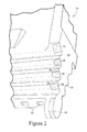
FIG. 2 is a perspective view of the turbine bucket ofFIG. 1 . - Referring to the drawings wherein identical reference numerals denote the same elements throughout the various views,
FIGS. 1 and2 show anexemplary turbine bucket 10, which is one of a plurality of such buckets mounted to aturbine rotor disk 12 that rotates about the centerline axis of a gas turbine engine. Thebucket 10 includes adovetail portion 14 for mounting thebucket 10 in acorresponding disk slot 16 formed in therotor disk 12. Specifically, thedovetail portion 14 includes one or more lobes (or mounting surfaces) 18 that engage one or morecomplementary lobes 20 on thedisk slot 16. Thedovetail portion 14 and thedisk slot 16 are shown to have the so-called fir tree shape although other suitable configurations may be utilized. Thebucket 10 is axially loaded into thedisk slot 16 and radially retained therein due to the complementary interlocking configurations of thedovetail lobes 18 and theslot lobes 20. Thebucket 10 is preferably formed as a one-piece casting of a suitable alloy, such as a nickel-based superalloy, which has acceptable strength at the elevated temperatures of operation in the gas turbine engine. - The
bucket 10 includes an airfoil portion (not shown) that extends radially outward from a platform abovedovetail portion 14. As is known in the art, the airfoil portion has an internal cooling circuit through which a suitable coolant is passed to keep the bucket temperature within design limits. The coolant enters the internal cooling circuit through one or more inlets 22 (FIG. 2 ) formed in the bottom of thedovetail portion 14 and located in fluid communication with a passage at the bottom of thedisk slot 16. During operation of the gas turbine engine, coolant is delivered to the passage in a conventional manner, from a source that may include, but is not limited to, the engine's compressor. Coolant flows from the passage into the internal cooling circuit (not shown) of thebucket 10 through theinlets 22. - In accordance with an exemplary but nonlimiting implementation, a suitable resin material, e.g., a silicon resin, may be applied to selected areas of the bucket dovetail (and/or to the mating dovetail slot) by a painting process which eliminates the need for time-consuming and costly masking and unmasking processes required in the prior metal spray seal techniques.
- One such suitable resin is available from Aremco Products, Inc. under the trade name "Corr-Paint™ CP40XX Series." The resin is formulated to be serviceable, or in other words, able to withstand prolonged exposure to temperatures of about 1100°F. Other suitable resins with the required properties would also be employed.
- As shown in
FIG. 1 , the seal comprises strips orpatches 24 of material (or, simply, seals 24) strategically placed on the undersides of thedovetail lobes 18, at least at the low pressure end thereof, so as to fill corresponding gaps 26 (Figure 1 ) between thedovetail lobes 18 and theslot lobes 20. Thus, theseals 24 prevent coolant leakage from the corresponding low pressure end of thedisk slot 16. It should be noted however that this is simply one exemplary seal arrangement used to illustrate the inventive concept. Other seal placements are possible depending on bucket design and the cooling configuration. - The foregoing has described a method of quickly and inexpensively applying dovetail seals to turbine buckets or rotor disks by essentially painting the resin material onto the lobes at selected locations. The method requires little surface preparation of the bucket and requires no masking. It will also be appreciated that the resin seal strips or
patches 24 may be applied at the manufacturing stage or at service intervals in the field. The silicon resin seals may also have applicability to compressor case abradable seals, to the dampening of a connection slot between the compressor stators and ring, or to any other arrangement of components with mating mounting surfaces. - While specific embodiments of the present invention have been described, it will be apparent to those skilled in the art that various modifications thereto can be made without departing from the spirit and scope of the invention as defined in the appended claims.
Claims (14)
- A method of sealing one or more gaps (26) between mounting surfaces (18) on one component (10) and a groove (16) in another component (12) adapted to engage said mounting surfaces comprising:a) applying a resin (24) on selected portions of said mounting surfaces (18) of said one component (10); andb) engaging said mounting surfaces (18) of said one component (10) in said groove (16) of said another component (12).
- The method of claim 1, wherein said resin (24) is painted on said selected portions of said mounting surfaces (18).
- The method of claim 1 or 2, wherein said resin material (24) comprises a water dispersible silicon resin, serviceable to temperature of about 1100°F.
- The method any of the preceding claims, wherein said one component (10) comprises a turbine bucket dovetail (14) and said another component (12) comprises a rotor disk.
- The method of claim 4, wherein said bucket dovetail (14) comprises multiple lobes (18) and said resin material (24) in applied to undersides of said lobes.
- The method of claim 5 wherein said resin material (24) is applied at a low pressure end of said bucket dovetail (14).
- The method of any of claims 4 to 6, wherein said resin material (24) is applied when said bucket dovetail (14) is manufactured.
- A turbine blade (10) having a mounting portion (14) adapted to be received in a groove (16) having a substantially corresponding shape, wherein selected surface areas of said mounting portion (14) are coated with a water dispersible silicon resin (24) serviceable up to at least 1100°F.
- The turbine blade of claim 8, wherein said mounting portion (14) is substantially dove-tail shaped.
- The turbine blade of claim 8 or 9, wherein said mounting portion (14) comprises plural lobes (18), said selected surface areas comprising underside surfaces of said lobes (18).
- A sealing arrangement comprising a first component having a mounting portion adapted to be received in a groove formed in a second component having a substantially corresponding shape but with one or more gaps between said mounting portion and surface portions defining said groove, wherein selected surface areas of said mounting portion are coated with a water dispersible silicon resin serviceable up to at least 1100°F thereby sealing said one or more gaps.
- The sealing arrangement of claim 11, wherein said mounting portion is substantially dove-tail shaped.
- The sealing arrangement of claims 11 or 12, wherein said mounting portion comprises plural lobes, said selected surface areas comprising underside surfaces of said lobes.
- The sealing arrangement of any of claims 11 to 13, wherein said resin is a silicon resin.
Applications Claiming Priority (1)
| Application Number | Priority Date | Filing Date | Title |
|---|---|---|---|
| US12/232,224 US20100068062A1 (en) | 2008-09-12 | 2008-09-12 | Turbine bucket with dovetail seal and related method |
Publications (1)
| Publication Number | Publication Date |
|---|---|
| EP2163729A2 true EP2163729A2 (en) | 2010-03-17 |
Family
ID=41162700
Family Applications (1)
| Application Number | Title | Priority Date | Filing Date |
|---|---|---|---|
| EP09169710A Withdrawn EP2163729A2 (en) | 2008-09-12 | 2009-09-08 | Turbine bucket with dovetail seal and related method |
Country Status (4)
| Country | Link |
|---|---|
| US (1) | US20100068062A1 (en) |
| EP (1) | EP2163729A2 (en) |
| JP (1) | JP2010065690A (en) |
| CN (1) | CN101672200A (en) |
Families Citing this family (8)
| Publication number | Priority date | Publication date | Assignee | Title |
|---|---|---|---|---|
| FR2963383B1 (en) * | 2010-07-27 | 2016-09-09 | Snecma | DUST OF TURBOMACHINE, ROTOR, LOW PRESSURE TURBINE AND TURBOMACHINE EQUIPPED WITH SUCH A DAWN |
| US8985960B2 (en) | 2011-03-30 | 2015-03-24 | General Electric Company | Method and system for sealing a dovetail |
| EP2546465A1 (en) | 2011-07-14 | 2013-01-16 | Siemens Aktiengesellschaft | Blade root, corresponding blade, rotor disc, and turbomachine assembly |
| JP2013210254A (en) * | 2012-03-30 | 2013-10-10 | Canon Inc | Three-dimensional measuring device, three-dimensional measuring method and three-dimensional measuring program |
| CN102797509B (en) * | 2012-08-24 | 2014-09-17 | 中国南方航空工业(集团)有限公司 | Shock absorption/lubrication structure of turbine blade |
| US9175573B2 (en) | 2012-11-28 | 2015-11-03 | General Electric Company | Dovetail attachment seal for a turbomachine |
| US9982549B2 (en) * | 2012-12-18 | 2018-05-29 | United Technologies Corporation | Turbine under platform air seal strip |
| US10273816B2 (en) * | 2013-02-12 | 2019-04-30 | United Technologies Corporation | Wear pad to prevent cracking of fan blade |
Citations (1)
| Publication number | Priority date | Publication date | Assignee | Title |
|---|---|---|---|---|
| US6296172B1 (en) | 2000-03-28 | 2001-10-02 | General Electric Company | Method of sealing disk slots for turbine bucket dovetails |
Family Cites Families (5)
| Publication number | Priority date | Publication date | Assignee | Title |
|---|---|---|---|---|
| US4537632A (en) * | 1983-10-19 | 1985-08-27 | Sermatech International, Inc. | Spherical aluminum particles in coatings |
| JPH0777008A (en) * | 1993-09-09 | 1995-03-20 | Mitsubishi Heavy Ind Ltd | Blade groove structure of turbine |
| JP2848584B2 (en) * | 1994-06-23 | 1999-01-20 | 日本製紙株式会社 | Aqueous resin composition, its production method and use |
| US20070048140A1 (en) * | 2005-08-24 | 2007-03-01 | General Electric Company | Methods and apparatus for assembling gas turbine engines |
| US7311940B2 (en) * | 2005-11-04 | 2007-12-25 | General Electric Company | Layered paint coating for turbine blade environmental protection |
-
2008
- 2008-09-12 US US12/232,224 patent/US20100068062A1/en not_active Abandoned
-
2009
- 2009-09-04 JP JP2009204188A patent/JP2010065690A/en active Pending
- 2009-09-08 EP EP09169710A patent/EP2163729A2/en not_active Withdrawn
- 2009-09-10 CN CN200910176360.6A patent/CN101672200A/en active Pending
Patent Citations (1)
| Publication number | Priority date | Publication date | Assignee | Title |
|---|---|---|---|---|
| US6296172B1 (en) | 2000-03-28 | 2001-10-02 | General Electric Company | Method of sealing disk slots for turbine bucket dovetails |
Also Published As
| Publication number | Publication date |
|---|---|
| JP2010065690A (en) | 2010-03-25 |
| US20100068062A1 (en) | 2010-03-18 |
| CN101672200A (en) | 2010-03-17 |
Similar Documents
| Publication | Publication Date | Title |
|---|---|---|
| EP2163729A2 (en) | Turbine bucket with dovetail seal and related method | |
| US9630277B2 (en) | Airfoil having built-up surface with embedded cooling passage | |
| US8439639B2 (en) | Filter system for blade outer air seal | |
| EP0752052B1 (en) | Airfoil having a seal and an integral heat shield | |
| US8563080B2 (en) | Method of repairing a damaged abradable coating | |
| US8545183B2 (en) | Seal coating between rotor blade and rotor disk slot in gas turbine engine | |
| US11391165B2 (en) | Apparatus and method for masking under platform areas of airfoil components | |
| US20090116953A1 (en) | Turbine airfoil with platform cooling | |
| US7665961B2 (en) | Turbine outer air seal | |
| US7686568B2 (en) | Methods and apparatus for fabricating turbine engines | |
| US20090202355A1 (en) | Replaceable blade tip shroud | |
| US8282356B2 (en) | Apparatus and method for reducing wear in disk lugs | |
| US20180283193A1 (en) | Sealing part for a gas turbine and method for manufacturing such a sealing part | |
| EP3037625B1 (en) | Turbine wheel with composite bladed ring | |
| US20140242278A1 (en) | Split coating mask system for gas turbine engine component | |
| EP3255250B1 (en) | Method for simultaneously depositing multiple coatings on a turbine blade of a gas turbine engine | |
| EP2957721A1 (en) | Systems and methods for distributing cooling air in gas turbine engines | |
| CA2551889C (en) | Cooled shroud assembly and method of cooling a shroud | |
| US20150354369A1 (en) | Gas turbine engine airfoil platform cooling | |
| US20190316480A1 (en) | Seal assembly for gas turbine engine | |
| US11346227B2 (en) | Modular components for gas turbine engines and methods of manufacturing the same | |
| CA2957474A1 (en) | System and method for rejuvenating coated components of gas turbine engines |
Legal Events
| Date | Code | Title | Description |
|---|---|---|---|
| PUAI | Public reference made under article 153(3) epc to a published international application that has entered the european phase |
Free format text: ORIGINAL CODE: 0009012 |
|
| AK | Designated contracting states |
Kind code of ref document: A2 Designated state(s): AT BE BG CH CY CZ DE DK EE ES FI FR GB GR HR HU IE IS IT LI LT LU LV MC MK MT NL NO PL PT RO SE SI SK SM TR |
|
| STAA | Information on the status of an ep patent application or granted ep patent |
Free format text: STATUS: THE APPLICATION IS DEEMED TO BE WITHDRAWN |
|
| 18D | Application deemed to be withdrawn |
Effective date: 20140401 |