EP2163343A2 - Notched grind wheel and method to manufacture a rotor blade retention slot - Google Patents
Notched grind wheel and method to manufacture a rotor blade retention slot Download PDFInfo
- Publication number
- EP2163343A2 EP2163343A2 EP09250972A EP09250972A EP2163343A2 EP 2163343 A2 EP2163343 A2 EP 2163343A2 EP 09250972 A EP09250972 A EP 09250972A EP 09250972 A EP09250972 A EP 09250972A EP 2163343 A2 EP2163343 A2 EP 2163343A2
- Authority
- EP
- European Patent Office
- Prior art keywords
- notch
- blade retention
- grind wheel
- web
- axis
- Prior art date
- Legal status (The legal status is an assumption and is not a legal conclusion. Google has not performed a legal analysis and makes no representation as to the accuracy of the status listed.)
- Granted
Links
- 230000014759 maintenance of location Effects 0.000 title claims abstract description 46
- 238000000034 method Methods 0.000 title claims abstract description 13
- 238000004519 manufacturing process Methods 0.000 title 1
- 238000012986 modification Methods 0.000 description 2
- 230000004048 modification Effects 0.000 description 2
- 239000003082 abrasive agent Substances 0.000 description 1
Images




Classifications
-
- B—PERFORMING OPERATIONS; TRANSPORTING
- B24—GRINDING; POLISHING
- B24B—MACHINES, DEVICES, OR PROCESSES FOR GRINDING OR POLISHING; DRESSING OR CONDITIONING OF ABRADING SURFACES; FEEDING OF GRINDING, POLISHING, OR LAPPING AGENTS
- B24B19/00—Single-purpose machines or devices for particular grinding operations not covered by any other main group
- B24B19/02—Single-purpose machines or devices for particular grinding operations not covered by any other main group for grinding grooves, e.g. on shafts, in casings, in tubes, homokinetic joint elements
-
- B—PERFORMING OPERATIONS; TRANSPORTING
- B24—GRINDING; POLISHING
- B24B—MACHINES, DEVICES, OR PROCESSES FOR GRINDING OR POLISHING; DRESSING OR CONDITIONING OF ABRADING SURFACES; FEEDING OF GRINDING, POLISHING, OR LAPPING AGENTS
- B24B19/00—Single-purpose machines or devices for particular grinding operations not covered by any other main group
- B24B19/009—Single-purpose machines or devices for particular grinding operations not covered by any other main group for grinding profiled workpieces using a profiled grinding tool
-
- B—PERFORMING OPERATIONS; TRANSPORTING
- B24—GRINDING; POLISHING
- B24D—TOOLS FOR GRINDING, BUFFING OR SHARPENING
- B24D7/00—Bonded abrasive wheels, or wheels with inserted abrasive blocks, designed for acting otherwise than only by their periphery, e.g. by the front face; Bushings or mountings therefor
- B24D7/18—Wheels of special form
Definitions
- the present disclosure relates to process tooling and procedures to grind blade retention slots within a rotor disk of a gas turbine engine.
- a multiple of fan, compressor, and turbine section rotor blades are secured to respective disks.
- One attachment arrangement utilizes rotor blade roots that are complementarily received within respective blade retention slots formed in a rotor disk periphery.
- One exemplary configuration of a blade retention slot includes a convoluted profile with a multiple of lobes that generally increases in a transverse dimension from the blade retention slot base toward the disk periphery. These configurations are often referred to as a fir-tree slot. Although an effective operational configuration, the slot base is typically wider than the narrowest lobe such that the slot base may be a relatively difficult area to grind.
- An exemplary grind wheel according to an exemplary aspect includes a rim having at least one notch formed in the rim.
- An exemplary method of grinding a slot base of a blade retention slot within a rotor disk includes rotationally aligning a grind wheel about an axis of rotation to align a notch with first and second opposed lobes of a blade retention slot of a rotor disk.
- the grind wheel is transited along the blade retention slot such that the notch is passed between a lobe width defined by the first and second opposed lobes of the blade retention slot.
- the rotating grind wheel is transited along the blade retention slot to grind a slot base of the blade retention slot with a rim of the grind disk.
- Figure 1 schematically illustrates a gas turbine engine 10 which generally includes a fan section F, a compressor section C, a combustor section G, a turbine section T, an augmentor section A, and an exhaust duct assembly E.
- the compressor section C, combustor section G, and turbine section T are generally referred to as the core engine.
- An engine longitudinal axis X is centrally disposed and extends longitudinally through these sections.
- a rotor assembly 22 of the gas turbine engine 10 is illustrated. It should be understood that a multiple of rotor disks may be contained within each engine section such as the fan section, the compressor section and, the turbine section. Although a particular rotor assembly 22 is illustrated and described in the disclosed embodiment, other sections which have other blades such as fan blades, low pressure turbine blades, high pressure turbine blades, high pressure compressor blades and low pressure compressor blades will also benefit herefrom.
- the rotor assembly 22 includes a plurality of blades 24 (one shown) circumferentially disposed around a rotor disk 26.
- Each blade 24 generally includes an attachment section 28, a platform section 30, and an airfoil section 32 along a radial axis B.
- the rotor disk 26 generally includes a hub 34, a rim 36, and a web 38 which extends therebetween.
- Each of the blades 24 is received within a blade retention slot 40 formed within the rim 36 of the rotor disk 26 (also illustrated in Figure 2B ).
- the blade retention slot 40 includes a contour such as a fir-tree or bulb type which corresponds with a contour of the attachment section 28 to provide engagement therewith.
- the blade retention slot 40 is generally defined by a first convoluted side 42A, a second convoluted side 42B and a slot base 44 therebetween.
- the first convoluted side 42A includes a multiple of lobes 46AA, 46AB and 46AC with a multiple of pockets 48AA, 48AB and 48AC.
- the second convoluted side 42B likewise includes a multiple of lobes 46BA, 46BB, 46BC and a multiple of pockets 48BA, 48BB and 48BC.
- the blade retention slot 40 may be machined through various methodologies. Although a fir-tree type convoluted contour with a particular number of lobes and pockets are illustrated in the disclosed embodiment, it should be understood that any convoluted shape with any number of lobes and pockets may benefit herefrom.
- the distance between the most radial inward lobes 46AC, 46BC define a lobe width which is less than a width of the slot base 44. That is, a mismatch width which at least partially defines the slot base 44 is wider than the lobe width between lobes 46AC, 46BC. This has heretofore complicated grinding the slot base 44.
- a grind wheel 60 generally includes a hub 62 defined about an axis of rotation W, a rim 64 and a web 66 between the hub 62 and the rim 64.
- the rim 64 is defined about the web 66 and includes a grinding surface 68 and shape (also illustrated in Figure 3B ) to grind the slot base 44 to a desired contour.
- the rim 64 is of a greater width than the web 66 ( Figure 3B ) and generally defines the mismatch width.
- a notch axis N1, N2 is defined transverse to the axis of rotation W. That is each notch axis N1, N2 may be considered a secant line relative the rim 64. Each notch axis N1, N2 is defined within a plane generally parallel to the web 66 ( Figure 3B ) but through the rim 64.
- a first notch 70A and a second notch 70B are defined through the rim 64 along the respective notch axis N1, N2 at a distance from the grinding surface 68 such that the lobes 46AC, 46BC will pass through the notches 70A, 70B when the grind wheel 60 is in a predefined rotationally fixed position. The first notch 70A and the second notch 70B are located on opposing side faces of the web 66.
- first notch 70A and the second notch 70B may be formed in a generally standard size grind wheel such as that manufactured by Saint-Gobain Abrasives of Worcester, MA USA to provide significantly more grit area to grind the slot base 44 which facilitates a more consistent surface over the mismatch width.
- the mismatch width is generally defined by allowable mismatch locations at which one tool such as the grind wheel 60 intersects a surface formed by a different tool such as a cutting tool. The mismatch width is readily satisfied with, for example only, but one pass of the grind wheel 60.
- additional notches such as balance notches 71 ( Figure 3A ) may additionally be located on the grind wheel 60 to facilitate balanced operation thereof.
- the following methodology of one non-limiting embodiment may be utilized to grind the slot base 44 to a desired contour.
- the grind wheel 60 is first rotationally fixed to align the first notch 70A with the lobes 46AC, 46BC ( Figure 5A ) such that the first notch 70A is then passed between the lobes 46AC, 46BC in step 82 ( Figure 5B ).
- the grind wheel 60 is rotated about axis W at operational speed.
- the slot base 44 is ground as the grind wheel 60 is transited along the blade retention slot 40.
- the web 66 is of a lesser width than the narrowest lobe width between lobes 46AC, 46BC such that the grind wheel 60 may be transited along the blade retention slot 40 so that the relatively wider grinding surface 68 will readily grind the slot base 44 ( Figure 5C ).
- the grind wheel 60 is rotationally fixed to align the notch 70B with the lobes 46AC, 46BC in step 88 ( Figure 5D ) such that the notch 70B is passed between the lobes 46AC, 46BC ( Figure 5E ) to remove the grind wheel 60 from the blade retention slot 40 in step 90 ( Figure 5E ). This process may be repeated to grind each of the multiple of blade retention slots 40.
Landscapes
- Engineering & Computer Science (AREA)
- Mechanical Engineering (AREA)
- Polishing Bodies And Polishing Tools (AREA)
- Grinding And Polishing Of Tertiary Curved Surfaces And Surfaces With Complex Shapes (AREA)
- Structures Of Non-Positive Displacement Pumps (AREA)
Abstract
Description
- The present disclosure relates to process tooling and procedures to grind blade retention slots within a rotor disk of a gas turbine engine.
- In gas turbine engines, a multiple of fan, compressor, and turbine section rotor blades are secured to respective disks. One attachment arrangement utilizes rotor blade roots that are complementarily received within respective blade retention slots formed in a rotor disk periphery.
- One exemplary configuration of a blade retention slot includes a convoluted profile with a multiple of lobes that generally increases in a transverse dimension from the blade retention slot base toward the disk periphery. These configurations are often referred to as a fir-tree slot. Although an effective operational configuration, the slot base is typically wider than the narrowest lobe such that the slot base may be a relatively difficult area to grind.
- An exemplary grind wheel according to an exemplary aspect includes a rim having at least one notch formed in the rim.
- An exemplary method of grinding a slot base of a blade retention slot within a rotor disk according to an exemplary aspect includes rotationally aligning a grind wheel about an axis of rotation to align a notch with first and second opposed lobes of a blade retention slot of a rotor disk. The grind wheel is transited along the blade retention slot such that the notch is passed between a lobe width defined by the first and second opposed lobes of the blade retention slot. The rotating grind wheel is transited along the blade retention slot to grind a slot base of the blade retention slot with a rim of the grind disk.
- Various features will become apparent to those skilled in the art from the following detailed description of the disclosed non-limiting embodiment. The drawings that accompany the detailed description can be briefly described as follows:
-
Figure 1 is a schematic illustration of a gas turbine engine; -
Figure 2A is an expanded perspective view of a single rotor blade mounted to a rotor disk; -
Figure 2B is an expanded view of a blade retention slot of the rotor disk ofFigure 2A ; -
Figure 2C is a front view of a blade retention slot of the rotor disk ofFigure 2A ; -
Figure 3A is a side view of one non-limiting embodiment of a grind wheel to grind a slot base of a blade retention slot of a rotor disk; -
Figure 3B is a cross-sectional view of the grind wheel taken alongline 3B-3B inFigure 3A ; -
Figure 4 is a flowchart which illustrates one non-limiting embodiment of a method to grind a slot base of a blade retention slot of a rotor disk; -
Figure 5A is a schematic view of a grind wheel rotationally aligned with a first and second opposed lobe of a blade retention slot; -
Figure 5B is a schematic view of the grind wheel transiting into the blade retention slot; -
Figure 5C is a schematic view of the grind wheel grinding the slot base of the blade retention slot; -
Figure 5D is a schematic view of the grind wheel rotationally aligned with a first and second opposed lobe of a blade retention slot; and -
Figure 5E is a schematic view of the grind wheel stopped and transiting out of the blade retention slot. -
Figure 1 schematically illustrates agas turbine engine 10 which generally includes a fan section F, a compressor section C, a combustor section G, a turbine section T, an augmentor section A, and an exhaust duct assembly E. The compressor section C, combustor section G, and turbine section T are generally referred to as the core engine. An engine longitudinal axis X is centrally disposed and extends longitudinally through these sections. Although a particular engine configuration is illustrated and described in the disclosed embodiment, other engines will also benefit herefrom. - Referring to
Figure 2A , arotor assembly 22 of thegas turbine engine 10 is illustrated. It should be understood that a multiple of rotor disks may be contained within each engine section such as the fan section, the compressor section and, the turbine section. Although aparticular rotor assembly 22 is illustrated and described in the disclosed embodiment, other sections which have other blades such as fan blades, low pressure turbine blades, high pressure turbine blades, high pressure compressor blades and low pressure compressor blades will also benefit herefrom. - The
rotor assembly 22 includes a plurality of blades 24 (one shown) circumferentially disposed around arotor disk 26. Eachblade 24 generally includes anattachment section 28, aplatform section 30, and anairfoil section 32 along a radial axis B. Therotor disk 26 generally includes ahub 34, arim 36, and aweb 38 which extends therebetween. Each of theblades 24 is received within ablade retention slot 40 formed within therim 36 of the rotor disk 26 (also illustrated inFigure 2B ). Theblade retention slot 40 includes a contour such as a fir-tree or bulb type which corresponds with a contour of theattachment section 28 to provide engagement therewith. - Referring to
Figure 2C , theblade retention slot 40 is generally defined by a first convolutedside 42A, a second convolutedside 42B and aslot base 44 therebetween. The first convolutedside 42A includes a multiple of lobes 46AA, 46AB and 46AC with a multiple of pockets 48AA, 48AB and 48AC. The second convolutedside 42B likewise includes a multiple of lobes 46BA, 46BB, 46BC and a multiple of pockets 48BA, 48BB and 48BC. It should be understood that theblade retention slot 40 may be machined through various methodologies. Although a fir-tree type convoluted contour with a particular number of lobes and pockets are illustrated in the disclosed embodiment, it should be understood that any convoluted shape with any number of lobes and pockets may benefit herefrom. - The distance between the most radial inward lobes 46AC, 46BC define a lobe width which is less than a width of the
slot base 44. That is, a mismatch width which at least partially defines theslot base 44 is wider than the lobe width between lobes 46AC, 46BC. This has heretofore complicated grinding theslot base 44. - Referring to
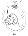
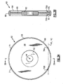
Figure 3A , agrind wheel 60 generally includes ahub 62 defined about an axis of rotation W, arim 64 and aweb 66 between thehub 62 and therim 64. Therim 64 is defined about theweb 66 and includes agrinding surface 68 and shape (also illustrated inFigure 3B ) to grind theslot base 44 to a desired contour. Therim 64 is of a greater width than the web 66 (Figure 3B ) and generally defines the mismatch width. - A notch axis N1, N2 is defined transverse to the axis of rotation W. That is each notch axis N1, N2 may be considered a secant line relative the
rim 64. Each notch axis N1, N2 is defined within a plane generally parallel to the web 66 (Figure 3B ) but through therim 64. Afirst notch 70A and asecond notch 70B are defined through therim 64 along the respective notch axis N1, N2 at a distance from thegrinding surface 68 such that the lobes 46AC, 46BC will pass through thenotches grind wheel 60 is in a predefined rotationally fixed position. Thefirst notch 70A and thesecond notch 70B are located on opposing side faces of theweb 66. - Notably, the
first notch 70A and thesecond notch 70B may be formed in a generally standard size grind wheel such as that manufactured by Saint-Gobain Abrasives of Worcester, MA USA to provide significantly more grit area to grind theslot base 44 which facilitates a more consistent surface over the mismatch width. The mismatch width is generally defined by allowable mismatch locations at which one tool such as thegrind wheel 60 intersects a surface formed by a different tool such as a cutting tool. The mismatch width is readily satisfied with, for example only, but one pass of thegrind wheel 60. It should be further understood that additional notches such as balance notches 71 (Figure 3A ) may additionally be located on thegrind wheel 60 to facilitate balanced operation thereof. - Referring to
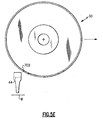
Figure 4 , the following methodology of one non-limiting embodiment may be utilized to grind theslot base 44 to a desired contour. Instep 80, thegrind wheel 60 is first rotationally fixed to align thefirst notch 70A with the lobes 46AC, 46BC (Figure 5A ) such that thefirst notch 70A is then passed between the lobes 46AC, 46BC in step 82 (Figure 5B ). Next, instep 84, thegrind wheel 60 is rotated about axis W at operational speed. Instep 86, theslot base 44 is ground as thegrind wheel 60 is transited along theblade retention slot 40. Theweb 66 is of a lesser width than the narrowest lobe width between lobes 46AC, 46BC such that thegrind wheel 60 may be transited along theblade retention slot 40 so that the relativelywider grinding surface 68 will readily grind the slot base 44 (Figure 5C ). Once theslot base 44 is ground, thegrind wheel 60 is rotationally fixed to align thenotch 70B with the lobes 46AC, 46BC in step 88 (Figure 5D ) such that thenotch 70B is passed between the lobes 46AC, 46BC (Figure 5E ) to remove thegrind wheel 60 from theblade retention slot 40 in step 90 (Figure 5E ). This process may be repeated to grind each of the multiple ofblade retention slots 40. - It should be understood that although a particular component arrangement is disclosed in the illustrated embodiment, other arrangements may also benefit from the disclosed exemplary embodiments.
- Although particular step sequences are shown, described, and claimed, it should be understood that steps may be performed in any order, separated or combined unless otherwise indicated.
- The foregoing description is exemplary rather than defined by the limitations within. Many modifications and variations are possible in light of the above teachings. Non-limiting embodiments are disclosed herein, however, one of ordinary skill in the art would recognize that certain modifications would come within the scope of this invention. It is, therefore, to be understood that within the scope of the appended claims, the invention may be practiced otherwise than as specifically described. For that reason the following claims should be studied to determine the true scope and content of this invention.
Claims (12)
- A grind wheel (60) comprising:a hub (62) defined about an axis of rotation (W);a web (66) defined about said hub (62); anda rim (64) defined about said web (66), said rim (64) having at least one notch (70A,70B).
- The grind wheel as recited in claim 1, wherein said at least one notch (70A,70B) is defined transverse to said axis of rotation (W) and generally parallel to a plane which contains said web (66).
- The grind wheel as recited in claim 1 or 2, wherein said at least one notch comprises a first notch (70A) on one side of said web (66) and a first notch (70A) on an opposite side of said web (66).
- The grind wheel as recited in claim 1, 2 or 3, wherein said at least one notch comprises a first notch (70A) and a second notch (70B) on one side of said web (66) and a first notch (70A) and a second notch (70B) on an opposite side of said web (66).
- The grind wheel as recited in any preceding claim, further comprising a first notch axis (N1) transverse to said axis of rotation (W), said at least one notch comprises a first notch (70A,70B) along said first notch axis (N1) on a first side of said web (66) and a second notch (70A,70B) along said first notch axis (N1) on said first side of said web (66).
- The grind wheel as recited in claim 5, further comprising a second notch axis (N2) transverse to said axis of rotation (W), said at least one notch comprises a first notch (70A,70B) along said second notch axis (N2) on a second side of said web (66) and a second notch (70A,70B) along said second notch axis (N2) on said second side of said web (66).
- A grind wheel (60) comprising:a hub (62) defined about an axis of rotation (W);a web (66) defined about said hub (62); anda rim (64) defined about said web (66), said rim (64) having a first notch (70A) and a second notch (70B) on one side of said web (66) and a first notch (70A) and a second notch (70B) on an opposite side of said web (66).
- The grind wheel as recited in claim 7, further comprising at least one balance notch (71) on said one side of said web (66) and a balance notch (71) on said opposite side of said web (66) to balance said grind wheel (60) about said axis of rotation (W).
- A method of grinding a slot base (44) of a blade retention slot (40) within a rotor disk (26) comprising:rotationally aligning a grind wheel (60) about an axis of rotation (W) to align a first notch (70A) with a first and second opposed lobe (46AC,46BC) of the blade retention slot (40) of the rotor disk (26);transiting the grind wheel (60) along the blade retention slot (40) so that the first notch (70A) is passed between a lobe width defined by the first and second opposed lobes (46AC,46BC) of the blade retention slot (40);rotating the grind wheel (60) about the axis of rotation (W); andtransiting the rotating grind wheel (60) along the blade retention slot (40) to grind a slot base (44) with a rim (64) of the grind disk (60), the slot base (44) having a width greater than the lobe width of the blade retention slot (40).
- A method as recited in claim 9, further comprising:stopping the grind wheel (60) to rotationally align the grind wheel (60) about the axis of rotation (W) to align a second notch (70B) with the first and second opposed lobes (46AC,46BC) of the blade retention slot (40); andtransiting the stopped grind wheel (60) out of the blade retention slot (40).
- A method as recited in claim 9 or 10, further comprising:rotating the rotor disk (26) to another blade retention slot (40).
- A method as recited in claim 9, 10 or 11, further comprising:transiting the grind wheel (60) along the blade retention slot (40) such that a web (66) of the grind wheel (60) passes between the lobe width defined by the first and second opposed lobes (46AC,46BC) of the blade retention slot (40).
Applications Claiming Priority (1)
| Application Number | Priority Date | Filing Date | Title |
|---|---|---|---|
| US12/207,912 US7846010B2 (en) | 2008-09-10 | 2008-09-10 | Notched grind wheel and method to manufacture a rotor blade retention slot |
Publications (3)
| Publication Number | Publication Date |
|---|---|
| EP2163343A2 true EP2163343A2 (en) | 2010-03-17 |
| EP2163343A3 EP2163343A3 (en) | 2013-07-10 |
| EP2163343B1 EP2163343B1 (en) | 2014-09-03 |
Family
ID=41328638
Family Applications (1)
| Application Number | Title | Priority Date | Filing Date |
|---|---|---|---|
| EP09250972.8A Expired - Fee Related EP2163343B1 (en) | 2008-09-10 | 2009-03-31 | Notched grind wheel and method to manufacture a rotor blade retention slot |
Country Status (2)
| Country | Link |
|---|---|
| US (2) | US7846010B2 (en) |
| EP (1) | EP2163343B1 (en) |
Families Citing this family (3)
| Publication number | Priority date | Publication date | Assignee | Title |
|---|---|---|---|---|
| US9802288B2 (en) | 2014-06-16 | 2017-10-31 | United Technologies Corporation | Machining system having a tool for finishing airfoils |
| CN109926894B (en) * | 2019-04-15 | 2020-11-06 | 南京航空航天大学 | Turbine disc tongue and groove forming grinding processing equipment and using method |
| CN112372451B (en) * | 2020-11-05 | 2022-11-08 | 中国航发哈尔滨东安发动机有限公司 | High-precision rotor blade and rim size control method thereof |
Citations (3)
| Publication number | Priority date | Publication date | Assignee | Title |
|---|---|---|---|---|
| US3579928A (en) | 1969-07-14 | 1971-05-25 | Gerhard R Held | Self-air cooling abrading wheel |
| US3711999A (en) | 1971-02-01 | 1973-01-23 | G Held | Self-air cooling abrading wheel |
| FR2886179A1 (en) | 2005-05-27 | 2006-12-01 | Snecma Moteurs Sa | Machining of a groove in the periphery of a component by a combined stitching and polishing operation with a single integrated machine, notably for a disc of a rotor for a turbine |
Family Cites Families (37)
| Publication number | Priority date | Publication date | Assignee | Title |
|---|---|---|---|---|
| US1614558A (en) * | 1921-09-30 | 1927-01-18 | Westinghouse Electric & Mfg Co | Method of cutting elemental slots in cylindrical bodies |
| US3146561A (en) * | 1961-05-01 | 1964-09-01 | Frederick W Lindblad | Circular saw and method of making the same |
| US3221728A (en) * | 1963-02-19 | 1965-12-07 | Frederick W Lindblad | Circular saw |
| US3590535A (en) * | 1969-04-24 | 1971-07-06 | Federal Mogul Corp | Diamond abrasive saw blade |
| US3599622A (en) * | 1969-07-18 | 1971-08-17 | Frank C Baron | Circular saw construction |
| US4267814A (en) * | 1979-12-06 | 1981-05-19 | Federal-Mogul Corporation | Abrasive saw blade for trapezoidal grooving |
| DE3006645A1 (en) | 1980-02-22 | 1981-09-03 | Frantisek 6380 Bad Homburg Flekac | Key-type joining device between components - has key and keyways of elliptical cross=section |
| DE3027504C2 (en) * | 1980-07-19 | 1983-05-11 | Hauni-Werke Körber & Co KG, 2050 Hamburg | Grinding machine |
| JPS58202709A (en) | 1982-05-19 | 1983-11-26 | Hitachi Ltd | Turbine rotor axial groove machining method and device |
| JPS58217233A (en) | 1982-06-07 | 1983-12-17 | Hitachi Ltd | Turpin blade processing equipment |
| FR2544855B1 (en) * | 1983-04-20 | 1986-02-21 | Snecma | METHOD AND DEVICE FOR MEASURING THE PRECISION OF THE HEIGHT OF BLADES OF A ROTOR |
| US4505075A (en) * | 1983-05-16 | 1985-03-19 | General Electric Company | Fixturing device |
| US4512115A (en) * | 1983-06-07 | 1985-04-23 | United Technologies Corporation | Method for cylindrical grinding turbine engine rotor assemblies |
| US4550708A (en) * | 1983-07-06 | 1985-11-05 | Federal-Mogul Corporation | Abrasive cutting wheel for cutting rock-like material |
| EP0185136A1 (en) * | 1984-11-26 | 1986-06-25 | Ikuo Shiga | Diamond circular saw |
| US4705017A (en) * | 1985-08-19 | 1987-11-10 | Federal-Mogul Corporation | Stress resistant abrasive cutting wheel |
| DE3862891D1 (en) * | 1987-05-04 | 1991-06-27 | Siemens Ag | METHOD FOR PRODUCING PROFILE PARTS BY GRINDING AND TURBO MACHINE BLADES PRODUCED accordingly. |
| US4924637A (en) * | 1987-10-21 | 1990-05-15 | Ngk Insulators, Ltd. | Method of machining ceramic rotor for pressure wave type supercharger |
| ZA896251B (en) * | 1988-08-27 | 1990-05-30 | Winter & Sohn Ernst | Saw |
| US5176480A (en) * | 1990-06-11 | 1993-01-05 | Carboloy Inc. | Broaching apparatus and methods |
| US5152669A (en) * | 1990-06-26 | 1992-10-06 | Westinghouse Electric Corp. | Turbomachine blade fastening |
| DE4114409A1 (en) | 1991-05-03 | 1992-10-29 | Heller Geb Gmbh Maschf | Quill type drill head with in-cycle tool change capability - has continuously driven quill spindles which can be selectively advanced to bring different tools into action |
| DE4120640A1 (en) | 1991-06-21 | 1992-12-24 | Kolbenschmidt Ag | NC lathe for fine boring gudgeon pin holes of I.C. engine pistons - has headstock, tailstock and work supporting cross=slide on bed moulded from rock and epoxy resin mix |
| JPH0531629A (en) | 1991-07-26 | 1993-02-09 | Fanuc Ltd | Electric discharge machining device |
| JPH06270006A (en) | 1993-03-19 | 1994-09-27 | Hitachi Ltd | Working of arcuate root groove of turbine moving blade |
| US5430936A (en) * | 1993-12-27 | 1995-07-11 | United Technologies Corporation | Method for making gas turbine engine blade attachment slots |
| KR0175176B1 (en) * | 1994-09-16 | 1999-02-18 | 하라 데라오 | Braid and Manufacturing Method |
| FR2725239B1 (en) * | 1994-09-30 | 1996-11-22 | Gec Alsthom Electromec | PROVISION FOR THE SHARPING OF STRESS SPIKES IN THE ANCHORAGE OF A TURBINE BLADE, COMPRISING A ROOT CALLED IN "FOOT-FIR" |
| DE19611276C1 (en) * | 1996-03-22 | 1997-03-20 | Walter Ag | Rotary groove-cutting tool |
| DE19855045C2 (en) * | 1998-11-28 | 2003-01-02 | Walter Ag | Precision milling cutter equipped with cutting inserts |
| JP3364168B2 (en) | 1999-05-17 | 2003-01-08 | 三菱重工業株式会社 | Blade groove machining cutter and blade groove machining method using the cutter |
| US6302651B1 (en) * | 1999-12-29 | 2001-10-16 | United Technologies Corporation | Blade attachment configuration |
| DE10033101A1 (en) * | 2000-07-07 | 2002-01-17 | Hilti Ag | Disc-shaped cutting tool |
| GB2382317B (en) | 2001-11-22 | 2004-05-12 | Quill Internat Ind Plc | Abrasive blasting apparatus |
| US6883234B2 (en) * | 2002-10-07 | 2005-04-26 | United Technologies Corporation | Process for machining axial blade slots in turbine disks for jet engines |
| US7007382B2 (en) * | 2003-07-24 | 2006-03-07 | United Technologies Corporation | Slot machining |
| US9662721B2 (en) * | 2008-02-26 | 2017-05-30 | United Technologies Corporation | Method of generating a curved blade retention slot in a turbine disk |
-
2008
- 2008-09-10 US US12/207,912 patent/US7846010B2/en active Active
-
2009
- 2009-03-31 EP EP09250972.8A patent/EP2163343B1/en not_active Expired - Fee Related
-
2010
- 2010-08-30 US US12/870,903 patent/US8313358B2/en not_active Expired - Fee Related
Patent Citations (3)
| Publication number | Priority date | Publication date | Assignee | Title |
|---|---|---|---|---|
| US3579928A (en) | 1969-07-14 | 1971-05-25 | Gerhard R Held | Self-air cooling abrading wheel |
| US3711999A (en) | 1971-02-01 | 1973-01-23 | G Held | Self-air cooling abrading wheel |
| FR2886179A1 (en) | 2005-05-27 | 2006-12-01 | Snecma Moteurs Sa | Machining of a groove in the periphery of a component by a combined stitching and polishing operation with a single integrated machine, notably for a disc of a rotor for a turbine |
Also Published As
| Publication number | Publication date |
|---|---|
| US20100062686A1 (en) | 2010-03-11 |
| US7846010B2 (en) | 2010-12-07 |
| US20100323596A1 (en) | 2010-12-23 |
| EP2163343A3 (en) | 2013-07-10 |
| US8313358B2 (en) | 2012-11-20 |
| EP2163343B1 (en) | 2014-09-03 |
Similar Documents
| Publication | Publication Date | Title |
|---|---|---|
| US7007382B2 (en) | Slot machining | |
| US7637010B2 (en) | Methods for machining turbine engine components | |
| US10273815B2 (en) | Curved blade retention slot for turbine blade in a turbine disk | |
| CA2708467C (en) | Method and apparatus for providing rotor discs | |
| EP3054088B1 (en) | Gas turbine engine rotor disk balancing | |
| CN103244198A (en) | Turbine assembly | |
| US10808536B2 (en) | Device for cooling a turbomachine rotor | |
| EP2163343B1 (en) | Notched grind wheel and method to manufacture a rotor blade retention slot | |
| JP4870754B2 (en) | Rotor blade / disc dovetail backcut to reduce stress on rotor blade / disk (7FA + e, 2nd stage) | |
| US8845392B2 (en) | Arrangement for grinding and a method thereof | |
| EP2527595A2 (en) | Balancing of rotatable components for a gas turbine engine | |
| US8689441B2 (en) | Method for machining a slot in a turbine engine rotor disk | |
| JP2008540920A (en) | Rotor blade / disk dovetail backcut to reduce stress on rotor blade / disk (9FA + e, 2nd stage) | |
| EP3415276B1 (en) | Method for grinding tip of rotor blade, and jig for grinding tip of blisk | |
| EP2394786A2 (en) | Finishing tool for turbomachine components | |
| EP3279436B1 (en) | Gas turbine wheel assembly and method of mounting a blade to a gas turbine wheel |
Legal Events
| Date | Code | Title | Description |
|---|---|---|---|
| PUAI | Public reference made under article 153(3) epc to a published international application that has entered the european phase |
Free format text: ORIGINAL CODE: 0009012 |
|
| AK | Designated contracting states |
Kind code of ref document: A2 Designated state(s): AT BE BG CH CY CZ DE DK EE ES FI FR GB GR HR HU IE IS IT LI LT LU LV MC MK MT NL NO PL PT RO SE SI SK TR |
|
| AX | Request for extension of the european patent |
Extension state: AL BA RS |
|
| PUAL | Search report despatched |
Free format text: ORIGINAL CODE: 0009013 |
|
| AK | Designated contracting states |
Kind code of ref document: A3 Designated state(s): AT BE BG CH CY CZ DE DK EE ES FI FR GB GR HR HU IE IS IT LI LT LU LV MC MK MT NL NO PL PT RO SE SI SK TR |
|
| AX | Request for extension of the european patent |
Extension state: AL BA RS |
|
| RIC1 | Information provided on ipc code assigned before grant |
Ipc: B24B 19/02 20060101AFI20130606BHEP Ipc: B24D 7/18 20060101ALI20130606BHEP |
|
| 17P | Request for examination filed |
Effective date: 20140109 |
|
| RBV | Designated contracting states (corrected) |
Designated state(s): AT BE BG CH CY CZ DE DK EE ES FI FR GB GR HR HU IE IS IT LI LT LU LV MC MK MT NL NO PL PT RO SE SI SK TR |
|
| AKX | Designation fees paid |
Designated state(s): DE GB |
|
| GRAP | Despatch of communication of intention to grant a patent |
Free format text: ORIGINAL CODE: EPIDOSNIGR1 |
|
| INTG | Intention to grant announced |
Effective date: 20140325 |
|
| GRAS | Grant fee paid |
Free format text: ORIGINAL CODE: EPIDOSNIGR3 |
|
| GRAA | (expected) grant |
Free format text: ORIGINAL CODE: 0009210 |
|
| AK | Designated contracting states |
Kind code of ref document: B1 Designated state(s): DE GB |
|
| REG | Reference to a national code |
Ref country code: GB Ref legal event code: FG4D |
|
| REG | Reference to a national code |
Ref country code: DE Ref legal event code: R096 Ref document number: 602009026397 Country of ref document: DE Effective date: 20141016 |
|
| REG | Reference to a national code |
Ref country code: DE Ref legal event code: R097 Ref document number: 602009026397 Country of ref document: DE |
|
| PLBE | No opposition filed within time limit |
Free format text: ORIGINAL CODE: 0009261 |
|
| STAA | Information on the status of an ep patent application or granted ep patent |
Free format text: STATUS: NO OPPOSITION FILED WITHIN TIME LIMIT |
|
| 26N | No opposition filed |
Effective date: 20150604 |
|
| REG | Reference to a national code |
Ref country code: DE Ref legal event code: R119 Ref document number: 602009026397 Country of ref document: DE |
|
| GBPC | Gb: european patent ceased through non-payment of renewal fee |
Effective date: 20150331 |
|
| PG25 | Lapsed in a contracting state [announced via postgrant information from national office to epo] |
Ref country code: DE Free format text: LAPSE BECAUSE OF NON-PAYMENT OF DUE FEES Effective date: 20151001 Ref country code: GB Free format text: LAPSE BECAUSE OF NON-PAYMENT OF DUE FEES Effective date: 20150331 |