EP2163324A1 - Method of producing metal closed-section member - Google Patents
Method of producing metal closed-section member Download PDFInfo
- Publication number
- EP2163324A1 EP2163324A1 EP09167697A EP09167697A EP2163324A1 EP 2163324 A1 EP2163324 A1 EP 2163324A1 EP 09167697 A EP09167697 A EP 09167697A EP 09167697 A EP09167697 A EP 09167697A EP 2163324 A1 EP2163324 A1 EP 2163324A1
- Authority
- EP
- European Patent Office
- Prior art keywords
- press
- plate workpiece
- forming
- die
- formed plate
- Prior art date
- Legal status (The legal status is an assumption and is not a legal conclusion. Google has not performed a legal analysis and makes no representation as to the accuracy of the status listed.)
- Granted
Links
- 238000000034 method Methods 0.000 title claims abstract description 95
- 239000002184 metal Substances 0.000 title claims abstract description 88
- 238000005452 bending Methods 0.000 claims description 47
- 230000003993 interaction Effects 0.000 claims description 46
- 238000003825 pressing Methods 0.000 claims description 43
- 238000003466 welding Methods 0.000 claims description 29
- 230000008569 process Effects 0.000 description 46
- 238000004519 manufacturing process Methods 0.000 description 20
- 238000010586 diagram Methods 0.000 description 17
- 230000002093 peripheral effect Effects 0.000 description 14
- 229910000831 Steel Inorganic materials 0.000 description 13
- 239000010959 steel Substances 0.000 description 13
- 239000011324 bead Substances 0.000 description 5
- 230000000994 depressogenic effect Effects 0.000 description 3
- 238000006073 displacement reaction Methods 0.000 description 3
- 239000011796 hollow space material Substances 0.000 description 3
- 239000013585 weight reducing agent Substances 0.000 description 3
- 230000008859 change Effects 0.000 description 2
- 239000000446 fuel Substances 0.000 description 2
- 230000007246 mechanism Effects 0.000 description 2
- 239000007769 metal material Substances 0.000 description 2
- 230000007547 defect Effects 0.000 description 1
- 230000006872 improvement Effects 0.000 description 1
- 238000012986 modification Methods 0.000 description 1
- 230000004048 modification Effects 0.000 description 1
Images












Classifications
-
- B—PERFORMING OPERATIONS; TRANSPORTING
- B21—MECHANICAL METAL-WORKING WITHOUT ESSENTIALLY REMOVING MATERIAL; PUNCHING METAL
- B21D—WORKING OR PROCESSING OF SHEET METAL OR METAL TUBES, RODS OR PROFILES WITHOUT ESSENTIALLY REMOVING MATERIAL; PUNCHING METAL
- B21D5/00—Bending sheet metal along straight lines, e.g. to form simple curves
- B21D5/01—Bending sheet metal along straight lines, e.g. to form simple curves between rams and anvils or abutments
- B21D5/015—Bending sheet metal along straight lines, e.g. to form simple curves between rams and anvils or abutments for making tubes
-
- B—PERFORMING OPERATIONS; TRANSPORTING
- B21—MECHANICAL METAL-WORKING WITHOUT ESSENTIALLY REMOVING MATERIAL; PUNCHING METAL
- B21D—WORKING OR PROCESSING OF SHEET METAL OR METAL TUBES, RODS OR PROFILES WITHOUT ESSENTIALLY REMOVING MATERIAL; PUNCHING METAL
- B21D47/00—Making rigid structural elements or units, e.g. honeycomb structures
- B21D47/01—Making rigid structural elements or units, e.g. honeycomb structures beams or pillars
-
- B—PERFORMING OPERATIONS; TRANSPORTING
- B21—MECHANICAL METAL-WORKING WITHOUT ESSENTIALLY REMOVING MATERIAL; PUNCHING METAL
- B21D—WORKING OR PROCESSING OF SHEET METAL OR METAL TUBES, RODS OR PROFILES WITHOUT ESSENTIALLY REMOVING MATERIAL; PUNCHING METAL
- B21D53/00—Making other particular articles
- B21D53/88—Making other particular articles other parts for vehicles, e.g. cowlings, mudguards
-
- Y—GENERAL TAGGING OF NEW TECHNOLOGICAL DEVELOPMENTS; GENERAL TAGGING OF CROSS-SECTIONAL TECHNOLOGIES SPANNING OVER SEVERAL SECTIONS OF THE IPC; TECHNICAL SUBJECTS COVERED BY FORMER USPC CROSS-REFERENCE ART COLLECTIONS [XRACs] AND DIGESTS
- Y10—TECHNICAL SUBJECTS COVERED BY FORMER USPC
- Y10T—TECHNICAL SUBJECTS COVERED BY FORMER US CLASSIFICATION
- Y10T29/00—Metal working
- Y10T29/49—Method of mechanical manufacture
- Y10T29/49616—Structural member making
- Y10T29/49622—Vehicular structural member making
Definitions
- the present invention relates to a method of producing a metal closed-section member formed in a cross-sectionally closed shape, from a metal plate workpiece.
- a vehicle body member making up a part of a basic structure of the vehicle body, such as a pillar member, a front or rear side frame, or a dash cross-member located in a lower region of a front surface of a dash panel, to achieve higher strength and rigidity, as well as weight reduction for improvement in fuel economy.
- the vehicle body member is comprised of a metal closed-section member, in many cases.
- a method which comprises subjecting each of a pair of metal plate workpieces, such as steel plates, to press working to form a pair of cross-sectionally hat-shaped (or cross-sectionally angular C-shaped) plate workpieces each integrally having a flange portion extending outwardly from a respective one of two free edges thereof, butting respective flange portions of the pair of cross-sectionally hat-shaped plate workpieces in such a manner as to define a closed-section space therebetween, and then welding the flange portions together to produce a metal closed-section member.
- a method of producing a triangular-shaped tube as a metal closed-section member comprising a first bending step of bending opposite ends of a steel plate pre-cut into a given shape, to have a given curvature, a second bending step of pressing and bending a central portion of the steel plate bent in the first bending step, a restraint-forming step of pressing the opposite ends of the steel plate bent in the second bending step, downwardly from thereabove, while applying restraint forces to the central portion of the steel plate from respective opposed rightward and leftward directions perpendicular to a longitudinal direction of the steel plate, so that the steel plate is formed under restraint into a given shape where the opposite ends are butted together, and a welding step of, after the restraint-forming step, welding the butted portions of the opposite ends without releasing the restraint forces, as disclosed, for example, in the Japanese Patent Laid-Open Publication No. 2000-51932 .
- the method disclosed in the Japanese Patent Laid-Open Publication No. 2000..51932 can produce a triangular closed-section shaped tube without providing a flange portion thereto.
- a vehicle body member for use in a vehicle such as an automobile, generally has a complicated shape, wherein a cross-sectional shape is highly likely to change complicatedly in a longitudinal direction of the member.
- the production method disclosed in the Japanese Patent Laid-Open Publication No. 2000-51932 is applied to a vehicle body member, it is necessary to prepare as a forming die a plurality of plates each formed with a cutout having the same shape as that of a cross section of a metal closed-section member to be formed.
- a method of producing a metal closed-section member formed in a cross-sectionally closed shape, from a metal plate workpiece comprises: a first press-forming step of providing a first forming die assembly, and, under a condition that the plate workpiece is clamped between a die and a blank holder of the first forming die assembly, causing relative movement of a punch of the first forming die assembly with respect to the die to allow the punch to be moved into a forming space of the die, so that the plate workpiece is press-formed into a shape convexly protruding in a direction of the movement of the punch relative to the die; and a second press-forming step of providing a second forming die assembly, and, after the first press-forming step, under a condition that the press-formed plate workpiece is positioned between a receiving die and a core die of the second forming die assembly, wherein the core die is disposed on the side opposite to the
- the method according to the first aspect of the present invention further comprises an end-bending step of, between the first press-forming step and the second press-forming step, bending at least one of respective ends of the sidewalls of the press-formed plate workpiece on the side opposite to the top wall, toward the inward side of the press-formed plate workpiece.
- the first press-forming step includes causing relative movement between the punch and the die of the first forming die assembly to allow the punch to be moved into the forming space of the die, so that the plate workpiece is press-formed into the shape convexly protruding in the direction of the movement of the punch relative to the die, and a convex wall portion is formed in the top wall of the press-formed plate workpiece to protrude in a direction opposite to the convexly protruding direction of the press-formed plate workpiece
- the second press-forming step includes, under a condition that the press-formed plate workpiece is held on the receiving die of the second forming die assembly while allowing the convex wall portion of the press-formed plate workpiece to be placed on a concave portion or a flat portion of the receiving die, pressing the convex wall portion of the press-formed plate workpiece in the convexly protruding direction of the press-formed plate workpiece to
- the convex wall portion of the top wall of the press-formed plate workpiece is formed in a cross-sectionally arc or trapezoidal shape.
- the method according to the first aspect of the present invention further comprises a final press-forming step of, after the second press-forming step, pressing respective ends of the cross-sectionally-closed sidewalls of the press-formed plate workpiece against a surface of the core die on an opposite side of a surface thereof used to press the top wall.
- the method according to the first aspect of the present invention further comprises a welding step of, after the second press-forming step, mutually welding the respective ends of the cross-sectionally-closed sidewalls of the press-formed plate workpiece.
- the core die of the second forming die assembly for use in the second press-forming step has a cross-sectional width less than that of the closed-section member.
- the first press-forming step includes forming the convex wall portion to divide the top wall into two top wall portions along a longitudinal direction of the press-formed plate workpiece, in such a manner that a cross-sectional length of at least one of the top wall portions of the top wall divided by the convex wall portion changes in the longitudinal direction, and the receiving die of the second forming die assembly for use in the second press-forming step is configured such that a cross-sectional length of a side surface of the concave portion of the receiving die is approximately equal to a shortest one of a plurality of cross-sectional lengths of the at least one top wall portion of the top wall.
- the first press-forming step is a preliminary bend-forming step of preliminarily bend-forming the plate workpiece into a given shape
- the second press-forming step includes an intrusion-forming sub-step of pressing the plate workpiece bend-formed in the preliminary bend-forming step, into the concave portion of the receiving die of the second forming die assembly by the core die of the second forming die assembly, to intrusion-form the bend-formed plate workpiece into a shape where at least one of opposite ends thereof extends in a direction opposite to a pressing direction of the core die and toward an inward side of the concave portion, and a final bend-forming sub-step of, under a condition that the core die is held within the plate workpiece intrusion-formed in the intrusion-forming sub-step, pressing and bending the ends of the intrusion-formed plate workpiece by a punch of the second forming die assembly to bring the ends of the intrusion-formed plate workpiece into contact with each
- the intrusion-forming sub-step includes moving the core die of the second forming die assembly into the concave portion of the receiving die of the second forming die assembly by driving means which is additionally used to move the punch of the second forming die assembly during the final bend-forming sub-step.
- the intrusion-forming sub-step includes moving the core die of the second forming die assembly into the concave portion while interposing a liner member between the core die and the punch of the second forming die assembly
- the final bend-forming sub-step includes, under a condition that the liner member is detached from between the core die and the punch of the second forming die assembly, and the core die is held within the plate workpiece intrusion-formed in the intrusion-forming sub-step, bending the ends of the intrusion-formed plate workpiece by the punch of the second forming die assembly.
- the method according to the ninth aspect of the present invention further comprises a welding step of, after the final bend-forming step, mutually welding the respective ends of the finally-bend-formed plate workpiece which are in contact with each other.
- the metal closed-section member production method comprises a first press-forming step of, under a condition that a metal plate workpiece is clamped between a die and a blank holder of a first forming die assembly, causing relative movement of a punch of the first forming die assembly with respect to the die to allow the punch to be moved into a forming space of the die, so that the plate workpiece is press-formed into a convexly protruding shape, and a second press-forming step of, under a condition that the press-formed plate workpiece is positioned between a receiving die and a core die of a second forming die assembly, causing relative movement of the core die with respect to the receiving die to allow a top wall of a convex-shaped portion of the press-formed plate workpiece to be press-formed into a given shape, so that two sidewalls of the convex-shaped portion on respective ones of both sides of the top wall are displaced toward the inward side of the press-formed plate workpiece and cross
- the metal closed-section member production method further comprises an end-bending step of, between the first press-forming step and the second press-forming step, bending at least one of respective ends of the sidewalls of the press-formed plate workpiece on the side opposite to the top wall, toward the inward side of the press-formed plate workpiece.
- the first press-forming step includes forming, in the top wall of the press-formed plate workpiece, a convex wall portion protruding in a direction opposite to the convexly protruding direction of the press-formed plate workpiece
- the second press-forming step includes pressing the convex wall portion of the press-formed plate workpiece to allow the convex wall portion of the press-formed plate workpiece to be flattened and formed as a press-formed wall, so that the sidewalls of the press-formed plate workpiece on the respective ones of both sides of the top wall are displaced toward the inward side of the press-formed plate workpiece and cross-sectionally closed together.
- the convex wall portion of the top wall of the press-formed plate workpiece is formed in a cross-sectionally arc or trapezoidal shape. This makes it possible to prevent the occurrence of crack or the like in the convex wall portion to effectively obtain the above advantages.
- the metal closed-section member production method further comprises a final press-forming step of pressing the ends of the cross-sectionally-closed sidewalls of the press-formed plate workpiece against a surface of the core die on an opposite side of a surface thereof to be used to press the top wall.
- the metal closed-section member production method further comprises a welding step of, after the second press-forming step, mutually welding the respective ends of the cross-sectionally-closed sidewalls of the press-formed plate workpiece. This makes it possible to increase joint strength of a metal closed-section member to produce a stronger metal closed-section member.
- the core die for use in the second press-forming step has a cross-sectional width less than that of the closed-section member.
- this feature makes it possible to prevent interference between the core die and the convex wall portion formed in the at least one sidewall during the second press-forming step for cross-sectionally closing the sidewalls together.
- the first press-forming step includes forming the convex wall portion in such a manner that a cross-sectional length of at least one of two top wall portion of the top wall divided by the convex wall portion changes in the longitudinal direction, and the receiving die of the second forming die assembly for use in the second press-forming step is configured such that a cross-sectional length of a side surface of the concave portion of the receiving die is approximately equal to a shortest one of a plurality of cross-sectional lengths of the at least one top wall portion of the top wall.
- the sidewalls can be press-formed on the respective ones of both sides of the press-formed wall at approximately the same timing. This makes it possible to stably perform the press-forming.
- the first press-forming step is a preliminary bend-forming step of preliminarily bend-forming the plate workpiece into a given shape
- the second press-forming step includes an intrusion-forming sub-step of pressing the bend-formed plate workpiece into the concave portion of the receiving die of the second forming die assembly by the core die of the second forming die assembly, to intrusion-form the bend-formed plate workpiece into a shape where at least one of opposite ends thereof extends in a direction opposite to a pressing direction of the core die and toward an inward side of the concave portion, and a final bend-forming sub-step of, under a condition that the core die is held within the intrusion-formed plate workpiece, pressing and bending the ends of the intrusion-formed plate workpiece by the punch of the second forming die assembly to bring the ends of the intrusion-formed plate workpiece into contact with each other by the punch and the core die, so that the intrusion-formed plate workpiece is formed into
- the intrusion-forming sub-step includes moving the core die of the second forming die assembly into the concave portion of the receiving die of the second forming die assembly by driving means which is additionally used to move the punch of the second forming die assembly during the final bend-forming sub-step.
- the intrusion-forming sub-step includes moving the core die of the second forming die assembly into the concave portion while interposing a liner member between the core die and the punch
- the final bend-forming sub-step includes, under a condition that the liner member is detached from between the core die and the punch, and the core die is held within the intrusion-formed plate workpiece, bending the ends of the intrusion-formed plate workpiece by the punch.
- the metal closed-section member production method further comprises a welding step of, after the final bend-forming step, mutually welding the respective ends of the press-formed plate workpiece which are in contact with each other. This makes it possible to increase joint strength of a metal closed-section member to produce a stronger metal closed-section member
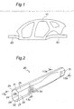
- FIG. 1 is a side view schematically showing a structure of an automobile body having a metal closed-section member produced by a method according to a first embodiment of the present invention.
- FIG. 2 is a perspective view showing a front side frame as a metal closed-section member produced by the method according to the first embodiment.
- FIG. 3A is a sectional view of the front side frame, taken along the line Y3a-Y3a in FIG. 2 .
- FIG. 3B is a sectional view of the front side frame, taken along the line Y3b-Y3b in FIG. 2 .
- FIG. 4 is a perspective view showing a draw-forming die assembly of a draw-forming apparatus for draw-forming a metal plate workpiece into a given shape.
- FIG. 5 is a sectional view of the draw-forming die assembly, taken along the line Y5-Y5 in FIG. 4 .
- FIGS. 6A and 6B are explanatory diagrams showing a draw-forming process.
- FIG. 7 is a perspective view showing a draw-formed plate workpiece
- FIG. 8 is a sectional view of the draw-formed plate workpiece, taken along the line Y8-Y8 in FIG. 7 .
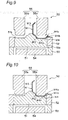
- FIG. 9 is a sectional view of an end-bending die assembly of an end-bending apparatus for bending respective ends of two sidewalls of the draw-formed plate workpiece.
- FIG. 10 is an explanatory diagrams showing an end-bending process.
- FIG. 11 is an explanatory diagrams showing the end-bending process.
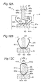
- FIGS. 12A to 12C are explanatory diagrams showing a press-forming process.
- FIG. 13 is a fragmentary enlarged view showing an area A in FIG. 12A .
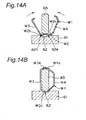
- FIGS. 14A and 14B are explanatory diagrams showing the press-forming process in a cross-section corresponding to that illustrated in FIG. 3B .
- FIGS. 15A and 15B are explanatory diagrams showing a final press-forming process.
- FIG. 16 is a perspective view showing a front side frame as a metal closed-section member produced by a method according to a second embodiment of the present invention.
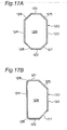
- FIG. 17A is a sectional view of the front side frame, taken along the line Y17a-Y17a in FIG. 16 .
- FIG. 17B is a sectional view of front side frame, taken along the line Y17b-Y17b in FIG. 16 .
- FIG. 18 is a perspective view showing a draw-forming die assembly of a draw-forming apparatus for draw-forming a metal plate workpiece into a given shape.
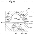
- FIG. 19 is a sectional view of the draw-forming die assembly, taken along the line Y19-Y19 in FIG. 18 .
- FIGS. 20A and 20B are explanatory diagrams showing a draw-forming process.
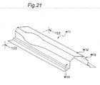
- FIG. 21 is a perspective view showing a draw-formed plate workpiece.
- FIG. 22 is a sectional view of the draw-formed plate workpiece, taken along the line Y22-Y22 in FIG. 21 .
- FIG. 23 is a sectional view showing an intrusion-forming die assembly of an intrusion-forming apparatus for intrusion-forming the draw-formed plate workpiece into given shape.
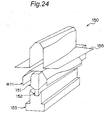
- FIG. 24 is a perspective view showing the intrusion-forming die assembly.
- FIGS. 25A and 25B are explanatory diagrams showing an intrusion-forming process.
- FIGS. 26A to 26C are explanatory diagrams showing a final bend-forming process.
- FIG. 1 is a side view schematically showing a structure of an automobile body having a metal closed-section member produced by a method according to a first embodiment of the present invention.
- the metal closed-section member production method according to the first embodiment is used for forming a metal plate workpiece into a cross-sectionally closed shape to produce a front side frame 20 to be connected to a side body 10 of the automobile, as shown in FIG. 1 .
- the present invention may be applied to production of any other suitable automobile body member, such as a rear side frame 30 to be connected to the side body 10.
- the present invention may be applied to production of any metal closed-section member other than the automobile body member.
- FIG. 2 is a perspective view showing a front side frame as a metal closed-section member produced by the method according to the first embodiment.
- FIG. 3A is a sectional view of the front side frame, taken along the line Y3a-Y3a in FIG. 2
- FIG. 3B is a sectional view of front side frame, taken along the line Y3b-Y3b in FIG. 2 .
- the front side frame 20 as a metal closed-section member produced by the method according to the first embodiment is formed as a metal member having a longitudinally long and cross-sectionally closed shape. More specifically, the front side frame 20 is formed in a cross-sectionally octagonal shape to have a hollow space 29 defined by a top wall 21, a bottom wall 22, a right sidewall 23, a left sidewall 24, a first inclined sidewall 25 inclinedly extending from the top wall 21 obliquely downwardly and rightwardly to the right sidewall 23, a second inclined sidewall 26 inclinedly extending from the top wall 21 obliquely downwardly and leftwardly to the left sidewall 24, a third inclined sidewall 27 inclinedly extending from the bottom wall 22 obliquely upwardly and rightwardly to the right sidewall 23, and a fourth inclined sidewall 28 inclinedly extending from the bottom wall 22 obliquely upwardly and leftwardly to the right sidewall 23.
- the front side frame 20 is formed such that the top wall 21 and the bottom wall 22 extend in parallel along a longitudinal direction of the front side frame 20 and have approximately the same cross-sectional length, whereas a cross-sectional shape changes in the longitudinal direction, as shown in FIG. 2 .
- the front side frame 20 is formed such that each of the first inclined sidewall 25 and the third inclined sidewall 27 in the cross-section illustrated in FIG. 3A has a cross-sectional length less than that of a corresponding one of the first inclined sidewall 25 and the third inclined sidewall 27 in the cross-section illustrated in FIG. 3B , and the right sidewall 23 in the cross-section illustrated in FIG. 3A has a cross-sectional length greater than that of the right sidewall 23 in the cross-section illustrated in FIG.
- each of the second inclined sidewall 26 and the fourth inclined sidewall 28 in the cross-section illustrated in FIG. 3A has a cross-sectional length greater than that of a corresponding one of the second inclined sidewall 26 and the fourth inclined sidewall 28 in the cross-section illustrated in FIG. 3B
- the left sidewall 24 in the cross-section illustrated in FIG. 3A has a cross-sectional length less than that of the left sidewall 24 in the cross-section illustrated in FIG. 3B
- Each of the third inclined side wall 27 and the fourth inclined side wall 28 is formed such that an inclination angle thereof relative to the bottom wall 22 has a given constant value in the longitudinal direction.
- the right sidewall 23 and the first inclined sidewall 25 are formed with a plurality of beads 31 each concavely protruding toward an inside of the hollow space 29.
- a plate blank made of a metal material and formed in an approximately flat shape, such as a steel plate, is prepared. Then, the plate workpiece is formed into a convex shape by a press-forming process, specifically a draw-forming process, and further formed into a given shape in conformity to a desired shape of the front side frame 20.
- FIG. 4 is a perspective view showing a draw-forming die assembly of a draw-forming apparatus for draw-forming a metal plate workpiece into a given shape.
- FIG. 5 is a sectional view of the draw-forming die assembly, taken along the line Y5-Y5 in FIG. 4 .
- FIG. 4 in regard to an after-mentioned die of the draw-forming die assembly, only a lower surface thereof is illustrated. Further, in regard to an after-mentioned blank holder of the draw-forming die assembly, only an upper surface thereof is illustrated.
- the draw-forming die assembly (first forming die assembly) 40 of the draw-forming apparatus for draw-forming a metal plate workpiece into a given shape comprises a blank holder 41 for holding a metal plate workpiece W 1, a punch 42 formed to have an outer peripheral surface 42a fitted in an inner peripheral surface 41a of the blank holder 41 and adapted to be movable relative to the blank holder 41 in an upward-downward direction, and a die 45 disposed in opposed relation to the blank holder 41 and the punch 42 and adapted to be movable in the upward-downward direction.
- the die 45 of the draw-forming die assembly 40 has a concave portion 45b concavely formed in a lower surface 45a thereof, so that a forming space 45c is defined inside the concave portion 45b to draw-form the plate workpiece W1 into a given shape.
- the concave portion 45b provided in the die 45 of the draw-forming die assembly 40 is formed in a given shape in conformity to the desired shape of the front side frame 20. Specifically, as shown in FIG.
- the concave portion 45b has a bottom surface 45d formed in an approximately flat or horizontal shape, a first inclined surface 45e inclinedly extending from the bottom surface 45d obliquely downwardly and rightwardly, a first right vertical surface 45f extending from the first inclined surface 45e vertically downwardly, a right horizontal surface 45g extending from the first right vertical surface 45f horizontally and rightwardly, a second right vertical surface 45h extending from the right horizontal surface 45g approximately vertically downwardly, a second inclined surface 45i inclinedly extending from the bottom surface 45d obliquely downwardly and leftwardly, a first left vertical surface 45j extending from the second inclined surface 45i vertically downwardly, a left horizontal surface 45k extending from the first left vertical surface 45j horizontally and leftwardly, and a second left vertical surface 451 extending from the left horizontal surface 45k approximately vertically downwardly.
- the bottom surface 45d of the concave portion 45b of the die 45 has a raised portion 45m formed in a cross-sectionally arc shape to protrude therefrom toward an inside of the forming space 45c. As shown in FIG. 4 , the raised portion 45m is formed on the bottom surface 45d to extend in a longitudinal direction of the die 45.
- the punch 42 of the draw-forming die assembly 40 is formed in a given shape in conformity to the desired shape of the front side frame 20 to form the plate workpiece W1 into a given shape in cooperation with the die 45 of the draw-forming die assembly 40. As shown in FIG.
- a head of punch 42 has a top surface 42d formed in an approximately flat or horizontal shape, a first inclined surface 42e inclinedly extending from the top surface 42d obliquely downwardly and rightwardly, a right vertical surface 42f extending from the first inclined surface 42e vertically downwardly, a right horizontal surface 42g extending from the right vertical surface 42f horizontally and rightwardly, a second inclined surface 42i inclinedly extending from the top surface 42d obliquely downwardly and leftwardly, a left vertical surface 42j extending from the second inclined surface 42i vertically downwardly, a left horizontal surface 42k extending from the left vertical surface 42j horizontally and leftwardly.
- the top surface 42d of the punch 42 has a depressed portion 42m formed in a sectionally arc shape to lower therefrom. The depressed portion 42m is formed in the top surface 42d to extend in the longitudinal direction of the die 45.
- the draw-forming apparatus equipped with the above draw-forming die assembly 40 is operable to move the punch 42 into the forming space 45c of the die 45 while clamping the plate workpiece W1 between the blank holder 41 and the die 45, to draw-form the plate workpiece W1 into a given shape in conformity to the desired shape of the front side frame 20.
- the second inclined surface 45i and the first left vertical surface 45j of the concave portion 45b have a plurality of bead-forming protrusions (not shown) each of which protrudes therefrom toward the inside of the forming space 45c in conformity to a shape of a respective one of the beads 31 of the front side frame 20.
- the second inclined surface 42i and the left vertical surface 42j have a plurality of bead-forming grooves (not shown) each concavely formed in conformity to the shape of the respective one of the beads 31.
- the plate workpiece W1 is held on the upper surface 41b of the blank holder 41, as shown in FIG. 5 .
- the die 45 of the draw-forming die assembly 40 is moved downwardly to clamp opposite lateral (widthwise) ends of the plate workpiece W1 between the blank holder 41 and the die 45, and then the punch 42 is moved upwardly into the forming space 45c of the die 45 to draw-form the plate workpiece W1 into a given shape.
- FIGS. 6A and 6B are explanatory diagrams showing a draw-forming process, wherein FIG. 6A illustrates a state when the punch is being moved upwardly after the plate workpiece is clamped between the blank holder and the die, to draw-form the plate workpiece into an intermediate shape, and FIG. 6B illustrates a state after the punch is fully moved upwardly to further draw-form the plate workpiece into a final shape.
- FIG. 7 is a perspective view showing the draw-formed plate workpiece (i.e., the plate workpiece after the draw-forming), and FIG. 8 is a sectional view of the draw-formed plate workpiece, taken along the line Y8-Y8 in FIG. 7 . As shown in FIGS.
- a laterally central portion of the draw-formed plate workpiece W1 i.e., a portion of the draw-formed plate workpiece W1 other than the opposite lateral ends thereof which have been clamped between the blank holder 41 and the die 45, is press-formed in a shape convexly protruding in a direction of the movement of the punch 42 relative to the die 45, to have a top wall W2 of a convex-shaped portion (hereinafter arbitrarily referred to as a protruded top wall W2) of the press-formed plate workpiece, and two sidewalls W3, W4 of the convex-shaped portion (hereinafter arbitrarily referred to as protruded sidewalls W3, W4) of the press-formed plate workpiece on respective ones of both sides of the top wall W2.
- the protruded top wall W2 is formed by an interaction between the bottom surface 45d of the concave portion 45b of the die 45, and the top surface 42d of the punch 42, wherein the protruded top wall W2 had a convex wall portion W2a formed to protrude in a cross-sectionally arc in a direction opposite to the convexly protruding direction of the draw-formed plate workpiece W1 and extend in a longitudinal direction of the draw-formed plate workpiece W1, by an interaction between the raised portion 45m of the bottom surface 45d and the depressed portion 42m of the top surface 42d. As shown in FIG.
- the protruded top wall W2 is divided by the convex wall portion W2a, into a right top wall portion W2b located on a right side of the convex wall portion W2a, and a left top wall portion W2c located on a left side of the convex wall portion W2a, wherein each of the wall portions W2b, W2c divided by the convex wall portion W2a of the protruded top wall W2 is formed such that a cross-sectional length thereof in the lateral direction changes in the longitudinal direction.
- the protruded sidewall W3 is formed on a right side of the protruded top wall W2 by an interaction between each of the first inclined surface 45e, the first right vertical surface 45f, the right horizontal surface 45g and the second right vertical surface 45h in the concave portion 45b of the die 45, and a corresponding one of the first inclined surface 42e, the right vertical surface 42f, the right horizontal surface 42g and the outer peripheral surface 42a in the punch 42.
- the protruded sidewall W3 has a first right sidewall portion W3a formed by the interaction between the first inclined surface 45e of the concave portion 45b and the first inclined surface 42e of the punch 42, to inclinedly extend from the protruded top wall W2, specifically the right top wall portion W2b, obliquely downwardly and rightwardly, a second right sidewall portion W3b formed by the interaction between the first right vertical surface 45f of the concave portion 45b and the right vertical surface 42f of the punch 42, to extend from the first right sidewall portion W3a vertically downwardly, a third right sidewall portion W3c formed by the interaction between the right horizontal surface 45g of the concave portion 45b and the right horizontal surface 42g of the punch 42, to extend from the second right sidewall portion W3b horizontally and rightwardly, and a fourth right sidewall portion W3d formed by the interaction between the second right vertical surface 45h of the concave portion 45b and the outer peripheral surface 42a of the punch 42, to extend from the pro
- the protruded sidewall W4 is formed on a left side of the protruded top wall W2 by an interaction between each of the second inclined surface 45i, the first left vertical surface 45j, the left horizontal surface 45k and the second left vertical surface 451 in the concave portion 45b of the die 45, and a corresponding one of the second inclined surface 42i, the left vertical surface 42j, the left horizontal surface 42k and the outer peripheral surface 42a in the punch 42.
- the protruded sidewall W4 has a first left sidewall portion W4a formed by the interaction between the second inclined surface 45i of the concave portion 45b and the second inclined surface 42i of the punch 42, to inclinedly extend from the protruded top wall W2, specifically the left top wall portion W2c, obliquely downwardly and leftwardly, a second left sidewall portion W4b formed by the interaction between the first left vertical surface 45j of the concave portion 45b and the left vertical surface 42j of the punch 42, to extend from the first left sidewall portion W4a vertically downwardly, a third left sidewall portion W4c formed by the interaction between the left horizontal surface 45k of the concave portion 45b and the left horizontal surface 42k of the punch 42, to extend from the second left sidewall portion W4b horizontally and rightwardly, and a fourth left sidewall portion W4d formed by the interaction between the second left vertical surface 451 of the concave portion 45b and the outer peripheral surface 42a of the punch 42, to extend from
- a plurality of beads W4f are formed in the protruded sidewall W4 of the draw-formed plate workpiece W1, specifically in the first and second left sidewall portions W4a, W4b, by an interaction between corresponding ones of the bead-forming protrusions formed on the second inclined surface 45i and the first left vertical surface 45j, and the bead-forming grooves formed in the second inclined surface 42i and the left vertical surface 42j of the punch 40.
- Each of the convex wall portion W2a, the right top wall portion W2b and the left top wall portion W2c in the protruded top wall W2 is formed in conformity of a shape of a respective one of the bottom wall 22, the fourth inclined sidewall 28 and the third inclined sidewall 27 in the front side frame 20. Further, the first right sidewall portion W3a of the protruded sidewall W3 is formed in conformity of a shape of the left sidewall 24 of the front side frame 20, and the second right sidewall portion W3b of the protruded sidewall W3 is formed in conformity of a shape of the second inclined sidewall 26 and the top wall 21 of the front side frame 20.
- the first left sidewall portion W4a of the protruded sidewall W4 is formed in conformity of a shape of the right sidewall 23 of the front side frame 20, and the second left sidewall portion W4b of the protruded sidewall W4 is formed in conformity of a shape of the first inclined sidewall 25 and the top wall 21 of the front side frame 20.
- the draw-forming of the plate workpiece W1 is performed under a condition that the opposite lateral ends of the plate workpiece W1 are clamped between the blank holder 41 and the die 45. This prevents the occurrence of crimples in the draw-formed plate workpiece W1
- a portion of the draw-formed plate workpiece W1 located below a blanking line L1 illustrated in FIG. 8 is blanked by blanking means (not shown), to cut away the lateral ends W5 of the draw-formed plate workpiece W1 which have been clamped between the blank holder 41 and the die 45, the third right sidewall portion W3c, the fourth right sidewall portion W3d, the third left sidewall portion W4c, and the fourth left sidewall portion W4d.
- FIG. 9 is a sectional view an end-bending die assembly of an end-bending apparatus for bending each of the ends of the protruded sidewalls of the draw-formed plate workpiece.
- the end-bending die assembly 50 of the end-bending apparatus for bending each of the ends W3e, W4e of the protruded sidewalls W3, W4 of the draw-formed plate workpiece W1 comprises a first die 51 for holding the draw-formed plate workpiece W1, a second die 52 fitted on an outer peripheral surface 51a of the first die 51, a third die 53 supporting the second die 52, a fourth die 54 disposed beneath the first die 51, and a punch 55 disposed in opposed relation to the first die 51 and adapted to be movable in an upward-downward direction.
- the first die 51 of the end-bending die assembly 50 is biased upwardly by biasing means (not shown), in such a manner that it is located at its initial position spaced apart from the fourth die 54.
- biasing means not shown
- FIG. 9 in order to bend-form the protruded sidewall W4 (specifically, the end W4e of the second left sidewall portion W4b) of the draw-formed plate workpiece W1 into a given shape, a right region of an upper surface 51b of the first die 51 is formed in conformity to the protruded top wall W2 and the protruded sidewall W4 of the draw-formed plate workpiece W1, to hold the draw-formed plate workpiece W1 while allowing the target end W4e of the second left sidewall portion W4b to be positioned on the second die 52.
- a left region of the upper surface 51b of the first die 51 is formed in conformity to the protruded top wall W2 and the protruded sidewall W3 of the draw-formed plate workpiece W1, to hold the draw-formed plate workpiece W1 while allowing the target end W3e of the second right sidewall portion W3b to be positioned on the second die 52.
- the punch 55 of the end-bending die assembly 50 comprises a right punch member 55a for pressing the draw-formed plate workpiece W1 held on the right region of the upper surface 51b of the first die 51, and a left punch member 55b for pressing the draw-formed plate workpiece W1 held on the left region of the upper surface 51 b of the first die 51.
- the end-bending apparatus equipped with the above end-bending die assembly 50 is operable to move the punch 55 downwardly while clamping the draw-formed plate workpiece between the first die 51 and the punch 55, to bend-form each of the ends W3e, W4e of the protruded sidewalls W3, W4 of the draw-formed plate workpiece W1 into a given shape by the second die 52.
- the first die 51 is set at the initial position by the upward biasing force of the biasing means, and the draw-formed plate workpiece W1 is held on the right region of the upper surface 51b of the first die 51 in a posture where the first left sidewall portion W4a is located at the lowermost position, as shown in FIG. 9 . Then, the punch 50 of the end-bending die assembly 50 is moved downwardly to perform the end-bending by an interaction between the punch 55 and the second die 52
- FIGS. 10 and 11 are explanatory diagrams showing an end-bending process, wherein FIG. 10 illustrates a state just after the punch being moved downwardly is brought into contact with the draw-formed plate workpiece, and FIG. 11 illustrates a state after the punch is further moved downwardly, and the end of the protruded sidewall of the draw-formed plate workpiece is bent.
- the first die 51 and the draw-formed plate workpiece W1 held on the first die 51 are moved upwardly to their initial positions. Then, as indicated by the two-dot chain line in FIG. 11 , the draw-formed plate workpiece W1 is turned 90 degrees, and held on the left region of the upper surface 51b of the first die 51 in a posture where the first right sidewall portion W3a is located at the lowermost position. Subsequently, in the same manner as that described above, the end W3e of the second left sidewall portion W3b of the protruded sidewall W3 is bent inwardly by an interaction between the left punch member 55a and the second die 52.
- the draw-formed plate workpiece W1 is press-formed to allow the convex wall portion W2a of the protruded top wall W2 to be pressed in the convexly protruding direction of the draw-formed plate workpiece W1, i.e., in a direction opposite to the protruding direction of the convex wall portion W2a, and formed into a given shape, so that the protruded sidewalls W3, W4 located on the respective ones of both sides to the protruded top wall W2 are displaced inwardly and cross-sectionally closed together.
- FIGS. 12A to 12C are explanatory diagrams showing a press-forming process, wherein FIG. 12A, FIG. 12B and FIG. 12C show, respectively, a state just after the draw-formed plate workpiece W1 is held on a press-forming die assembly of a press-forming apparatus for press-forming the draw-formed plate workpiece W1 into a cross-sectionally closed shape, a state when the convex wall portion of the protruded top wall of the draw-formed plate workpiece is being press-formed using a core die of the press-forming die assembly, and a state after the convex wall portion of the protruded top wall of the draw-formed plate workpiece is press-formed into a given shape by the core die of the press-forming die assembly so that the respective ends of the protruded sidewalls are butted together in such a manner that the protruded sidewalls are cross-sectionally closed together.
- a punch of the press-forming die assembly is omitted.
- the press-forming die assembly (second forming die assembly) 60 of the press-forming apparatus for press-forming the draw-formed plate workpiece W1 into a cross-sectionally closed shape comprises a receiving die 61 for holding the draw-formed plate workpiece W1, a core die 65 disposed above the receiving die 61 and adapted to be movable in an upward-downward direction, and a punch 67 disposed above the core die 65 and adapted to be movable in the upward-downward direction.
- the receiving die 61 of the press-forming die assembly 60 has an upper surface 61a for holding the protruded top wall W2 of the draw-formed plate workpiece W1, and a concave portion 62 is concavely formed in the upper surface 61 a, as shown in FIG. 12A .
- FIG. 13 is a fragmentary enlarged view showing an area A in FIG. 12A .
- the concave portion 62 provided in the receiving die 61 of the press-forming die assembly 60 has a bottom surface 62a, and two opposed side surfaces 62b, 62c, specifically a right side surface 62a located on a right side in FIG. 13 and a left side surface 62c located on a left side in FIG. 13 , wherein the concave portion extends in a longitudinal direction of the receiving die 61.
- the bottom surface 62a of the concave portion 62 provided in the receiving die 61 of the press-forming die assembly 60 is formed in conformity to a shape of the bottom wall 22 of the front side frame 20, to have a cross-sectional length of the convex wall portion W2a of the protruded sidewall W2 of the draw-formed plate workpiece W1, i.e., a cross-sectional length L21 approximately equal to an arc length L11 of the convex wall portion W2a in cross-section.
- Each of the side surfaces 62b, 62c of the concave portion 62 is formed to have a cross-sectional length approximately equal to a shortest one of a plurality of cross-sectional lengths of the protruded top wall W2 which change in the longitudinal direction of the draw-formed plate workpiece W1.
- the right side surface 62b of the concave portion 62 is formed to have a cross-sectional length L22 approximately equal to a shortest one of a plurality of cross-sectional lengths L12 of the left top wall portion W2c
- the left side surface 62c of the concave portion 62 is formed to have a cross-sectional length L23 approximately equal to a shortest one of a plurality of cross-sectional lengths L13 of the right top wall portion W2b.
- each of the side surfaces 62b, 62c of the concave portion 62 is formed such that an inclination angle thereof relative to the bottom surface 62a has a given constant value in the longitudinal direction, depending on the desired shape of the front side frame 20.
- the core die 65 of the press-forming die assembly 60 is disposed above the receiving die 61 to press the protruded top wall W2 of the draw-formed plate workpiece W1, specifically, the convex wall portion W2a of the protruded top wall W2, in the convexly protruding direction of the draw-formed plate workpiece W1.
- the core die 65 is formed to have a longitudinal length greater than that of the draw-formed plate workpiece W1. More specifically, as shown in FIG.
- the core die 65 has a top surface 65a, a bottom surface 65b, a right side surface 65c, a left side surface 65d, a first inclined side surface 65e inclinedly extending from the top surface 65a to the right side surface 65c obliquely downwardly and rightwardly, a second inclined side surface 65f inclinedly extending from the top surface 65a to the left side surface 65d obliquely downwardly and leftwardly, a third inclined side surface 65g inclinedly extending from the bottom surface 65b to the right side surface 65c obliquely upwardly and rightwardly, and a fourth inclined side surface 65h inclinedly extending from the bottom surface 65b to the left side surface 65d obliquely upwardly and leftwardly.
- Each of the bottom surface 65b, the third inclined side surface 65g and the fourth inclined side surface 65h in the core die 65 is formed in conformity to a shape of a corresponding one of the bottom wall 22, the third inclined sidewall 27 and the fourth inclined sidewall 28 in the front side frame 20. Further, each of the top surface 65a, the first inclined side surface 65e and the second inclined side surface 65f of the core die 65 is formed in conformity to a shape of a corresponding one of the top wall 21, the first inclined sidewall 25 and the second inclined sidewall 26 in the front side frame 20.
- the core die 65 of the press-forming die assembly 60 is formed to have a cross-sectional width less than that of the front side frame 20 when the draw-formed plate workpiece W1 is press-formed into a cross-sectionally closed shape. More specifically, as shown in FIG. 12C , the core die 65 is formed such that a cross-sectional width L31 thereof between the right side surface 65c and the left side surface 65d becomes less than a cross-sectional width L32 between the first left sidewall portion W4a and the first right sidewall portion W3a of the draw-formed plate workpiece W1, which corresponds to a cross-sectional width between the right sidewall 23 and the left sidewall 24 of the front side frame 20.
- a cross-sectional lateral length or width of the bottom surface 65d of the core die 65 is set to be approximately equal to the cross-sectional length L11 of the convex wall portion W2a of the draw-formed plate workpiece W1.
- the core die 65 is adapted, after the draw-formed plate workpiece W1 is press-formed into a cross-sectionally closed shape, to be pulled out from the draw-formed plate workpiece W1 in the longitudinal direction of the draw-formed plate workpiece W1.
- the punch 67 of the press-forming die assembly 60 is designed, after the respective ends W3e, W4e of the protruded sidewalls W3, W4 of the draw-formed plate workpiece W1 are butted together in such a manner that the protruded sidewalls W3, W4 are cross-sectionally closed together, to perform a final press-forming process of pressing the butted ends W3e, W4e of the protruded sidewalls W3, W4 against the surface (top surface) 65a of the core die 65 on an opposite side of the surface (bottom surface) 65b used for pressing the protruded top wall W2 (specifically, the convex wall portion W2a), as described later.
- the punch 67 is disposed immediately above the core die 65 and adapted to be movable in the upward-downward direction.
- the press-forming apparatus equipped with the above press-forming die assembly 60 is operable, under a condition that the draw-formed plate workpiece W1 is held on the receiving die 61 of the press-forming die assembly 60 while placing the convex wall portion W2a of the draw-formed plate workpiece W1 on the concave portion 62 of the receiving die 61, to allow the convex wall portion W2a of the draw-formed plate workpiece W1 to be press in the convexly protruding direction of the draw-formed plate workpiece W1 and formed into a given shape within the concave portion 62 by the core die 65 of the press-forming die assembly 60, so that the protruded sidewalls W3, W4 located on the respective ones of both sides of the protruded top wall W2 of the draw-formed plate workpiece W1 are displaced toward the inwardly and cross-sectionally closed together.
- the draw-formed plate workpiece W1 is placed on the receiving die 61 of the press-forming die assembly 60 to allow a lateral center of the convex wall portion W2a of the draw-formed plate workpiece W1 to be located approximately on a vertical axis of the concave portion 62 of the receiving die 61, and the protruded top wall W2 of the draw-formed plate workpiece W1 is held on the upper surface 61a of the receiving die 61, as shown in FIG. 12A .
- the core die 65 is moved downwardly to press the convex wall portion W2a of the draw-formed plate workpiece W1 downwardly, i.e., in the convexly protruding direction of the draw-formed plate workpiece W1, so that the left top wall W2c and the protruded sidewall W4 are displaced inwardly, i.e., in a direction allowing the draw-formed plate workpiece W1 to have a cross-sectionally closed shape, about a shoulder 62e of the receiving die 61 which is an intersection between the right side surface 62b of the concave portion 62 and the upper surface 61a, and the right top wall W2b and the protruded sidewall W3 are simultaneously displaced inwardly, i.e., in a direction allowing the draw-formed plate workpiece W1 to have a cross-sectionally closed shape, about a shoulder 62f of the receiving die 61 which is an intersection between the left
- the convex wall portion W2a is flattened and formed as a press-formed wall W2d by an interaction between the punch 65 and the receiving die 61, and the protruded sidewalls W3, W4 on the respective ones of both sides of the protruded top wall W2 are further displaced inwardly to allow the respective ends W3 e, W4e of the protruded sidewalls W3, W4 to be butted together in such a manner that the protruded sidewalls W3, W4 are cross-sectionally closed together, as shown in FIG. 12C .
- FIGS. 12A to 12C for illustrating the press-forming process shows a cross-section corresponding to that illustrated in FIG. 3A
- a remaining portion of the draw-formed plate workpiece W1 in any other cross-section such as a cross-section corresponding to that illustrated in FIG. 3B is simultaneously pressed and formed into a cross-sectionally closed shape.
- FIGS. 14A and 14B are explanatory diagrams showing the press-forming process in a cross-section corresponding to that illustrated in FIG. 3B , wherein FIG. 14A illustrates a state when the convex wall portion of the protruded top wall of the draw-formed plate workpiece is being pressed by the core die of the press-forming die assembly, and FIG.
- FIG. 14B illustrates a state after the convex wall portion of the protruded top wall of the draw-formed plate workpiece is press-formed into a given shape by the core die of the press-forming die assembly to allow the respective ends of the protruded sidewalls to be butted together in such a manner that the protruded sidewalls are cross-sectionally closed together.
- the convex wall portion W2a is flattened and formed as the press-formed wall W2d, by an interaction between the punch 65 and the receiving die 61, and the protruded sidewalls W3, W4 on the respective ones of both sides of the protruded top wall W2 are further displaced inwardly to allow the respective ends W3e, W4e of the protruded sidewalls W3, W4 to be butted together in such a manner that the protruded sidewalls W3, W4 are cross-sectionally closed together, as shown in FIG. 14B , in the same manner as that in FIG. 12C .
- the wall portions W2c, W2b of the protruded top wall W2 divided by the convex wall portion W2a are formed such that each of the cross-sectional lengths L12, L13 thereof changes in the longitudinal direction of the draw-formed plate workpiece W1, and press-formed using the receiving die 61 of the press-forming die assembly 60 configured such that each of the cross-sectional lengths L22, L23 of the side surfaces 62b, 62c of the concave portion 62 provided in the receiving die 61 is set to be approximately equal to a shortest one of the cross-sectional lengths L12, L13 of a corresponding one of the wall portions W2c, W2b of the protruded top wall W2.
- the top wall portions W2c, W2b corresponding to respective sidewalls to be formed on the respective ones of both sides of the press-formed wall W2d, specifically, respective ones of the third inclined sidewall 27 and the fourth inclined sidewall 28 of the front side frame 20, can be press-formed at approximately the same timing in the longitudinal direction. This makes it possible to stably perform the press-forming.
- FIGS. 15A and 15B are explanatory diagrams showing the final press-forming process, wherein FIG. 15A illustrates a state before the final press-forming, and FIG. 15B illustrates a state after the final press-forming.
- the punch 67 is used which is disposed immediately above the core die 65 and adapted to be movable in the upward-downward direction.
- the method according to the first embodiment includes the final press-forming process of pressing the butted ends W3e, W4e of the protruded sidewalls W3, W4 of the draw-formed plate workpiece W1 against the surface 65a on the side opposite to the surface 65b of the core die 65 used for pressing the convexly curving wall W2a.
- the butted ends of the protruded sidewalls are joined together by welding, such as laser welding, so that the front side frame 20 as a metal closed-section member formed in a cross-sectionally closed shape is produced without providing a flange portion thereto.
- the method according to the first embodiment includes the welding process of mutually welding the respective ends of the cross-sectionally-closed protruded sidewalls of the draw-formed plate workpiece. This makes it possible to increase joint strength of a metal closed-section member to produce a stronger metal closed-section member.
- the punch 42 is moved into the forming space 45c of the die 45 to draw-form the plate workpiece W1 into a shape convexly protruding in the direction of the movement of the punch 42 relative to the die 45, while allowing the convex wall portion W2a protruding in the direction opposite to the convexly protruding direction of the draw-formed plate workpiece W1 to be formed in the protruded top wall W2 of the draw-formed plate workpiece W1.
- any other suitable press-forming process such as stretch-forming, may be employed.
- the ends W3e, W4e of the protruded sidewalls W3, W4 of the draw-formed plate workpiece W1 are bended, and then the protruded sidewalls W3, W4 are cross-sectionally closed together.
- the protruded sidewalls W3, W4 may be cross-sectionally closed together without bending the ends W3e, W4e.
- the convex wall portion W2a of the draw-formed plate workpiece W1 is pressed within the concave portion 62 in the convexly protruding direction of the draw-formed plate workpiece W1 by the core die 65 of the press-forming die assembly 60, in such as manner as to be butted together to allow the protruded sidewalls W3, W4 to be cross-sectionally closed together.
- the ends W3e, W4e of the protruded sidewalls W3, W4 of the draw-formed plate workpiece W1 may be superimposed on each other in such a manner that the protruded sidewalls W3, W4 are cross-sectionally closed together.
- the superimposed ends W3e, W4e of the cross-sectionally-closed protruded sidewalls W3, W4 of the draw-formed plate workpiece W1 are preferably joined together by lap welding or fillet welding.
- the concave portion 62 is formed in the receiving die 61 of the press-forming die assembly 60.
- the plate workpiece W1 may be held on the receiving die 61 to allow the convex wall portion W2a of the draw-formed plate workpiece W1 to be placed on a flat portion of the receiving die 61 without forming the concave portion in the receiving die 61.
- the convex wall portion W2a of the draw-formed plate workpiece W1 may be pressed against the flat portion of the receiving die 61 of the press-forming die assembly 60 in the convexly protruding direction of the draw-formed plate workpiece W1 by the core die 65 of the press-forming die assembly 60, in such a manner as to be flattened and formed as a press-formed wall, so that the protruded sidewalls W3, W4 of the draw-formed plate workpiece W1 are displaced toward the inward side of the draw-formed plate workpiece W1 and cross-sectionally closed together.
- the production method for the front side frame 20 as a metal closed-section member comprises a first press-forming step of, under a condition that a metal plate workpiece W1 is clamped between a die 45 and a blank holder 41 of a first forming die assembly 40, moving a punch 42 of the first forming die assembly 40 into a forming space 45c of the die 45 to press-form the plate workpiece W1 into a shape convexly protruding in a direction of the movement of the punch 42 relative to the die 45, and a second press-forming step of after the first press-forming step, under a condition that the press-formed plate workpiece W1 is positioned between a receiving die 61 and a core die 65 of a second forming die assembly 60, wherein the core die 65 is disposed on the side opposite to the convexly protruding direction of the press-formed plate workpiece W1, moving the core die 65 relative to the receiving die 61 to allow a protruded top wall W
- the first press-forming step includes forming, in the protruded top wall W2 of the press-formed plate workpiece W1, a convex wall portion W2a protruding in a direction opposite to the convexly protruding direction of the press-formed plate workpiece W1, and the second press-forming step includes pressing the convex wall portion W2a of the press-formed plate workpiece W1 to allow the convex wall portion W2a of the press-formed plate workpiece W1 to be flattened and formed as a press-formed wall W2d, so that the protruded sidewalls W3, W4 of the press-formed plate workpiece W1 on the respective ones of both sides of the protruded top wall W2 are displaced toward the inward side of the press-formed plate workpiece W1 and cross-sectionally closed together.
- a metal closed-section member having a cross-sectional shape which changes in a longitudinal direction thereof, there is no need to employ a forming die adapted to surround a metal closed-section member.
- a metal closed-section member can be produced from a metal plate workpiece in a relatively simple manner.
- the convex wall portion W2a of the protruded top wall W2 of the press-formed plate workpiece W1 is formed in a cross-sectionally arc shape, and pressed to allow the protruded sidewalls W3, W4 on respective ones of both side of the protruded top wall of the press-formed plate workpiece W1 to be displaced toward the inward side of the press-formed plate workpiece W1.
- the convex wall portion of the protruded top wall W2 of the press-formed plate workpiece W1 may be formed in a cross-sectionally trapezoidal shape.
- the convex wall portion W2a of the protruded top wall W2 of the press-formed plate workpiece W1 may be formed in a cross-sectionally arc or trapezoidal shape. This makes it possible to prevent the occurrence of crack or the like when the convex wall portion W2a is flattened, to effectively obtain the above advantages.
- a cross-sectional length of the convex wall portion W2a of the protruded top wall W2 of the press-formed plate workpiece W1 is approximately equal to that of the press-formed wall W2d. This makes it possible to accurately form the press-formed wall to effectively obtain the above advantages.
- both the ends W3e, W4e of the protruded sidewalls W3, W4 of the press-formed plate workpiece W1 on the side opposite to the protruded top wall W2 are bent.
- only one of the ends W3e, W4e of the protruded sidewalls of the press-formed plate workpiece W1 on the side opposite to the protruded top wall may be bent inwardly.
- the method according to the first embodiment includes an end-bending step of, between the first press-forming step and the second press-forming step, bending at least one of respective ends W3e, W4e of the protruded sidewalls W3, W4 of the press-formed plate workpiece W1 on the side opposite to the protruded top wall W2, toward the inward side of the press-formed plate workpiece W1.
- This makes it possible to reduce displacement of the press-formed plate workpiece toward the inward side of the protruded sidewalls when the press-formed plate workpiece is formed into a cross-sectionally closed shape, to further accurately produce a metal closed-section member.
- the core die 65 having a cross-sectional width L31 less than that L32 of the front side frame 20 is used to press-form the press-formed plate workpiece W1 into a cross-sectionally closed shape.
- a convex wall portion protruding toward an inward side of a closed-section space of the press-formed plate workpiece W1 is also formed in at least one of the protruded sidewall W3, W4, this feature makes it possible to prevent interference between the core die and the convex wall portion formed in the at least one protruded sidewall, in the second press-forming step for forming the press-formed plate workpiece W1 into a cross-sectionally closed shape.
- the core die 65 is moved relative to the receiving die 61 to allow the protruded top wall W2 of the press-formed plate workpiece W11 to be pressed in the convexly protruding direction of the press-formed plate workpiece W1 and formed into a given shape, so that the protruded sidewalls W3, W4 of the press-formed plate workpiece W1 formed on the respective ones of both sides of the protruded top wall W2 during the first press-forming step are displaced toward the inward side of the press-formed plate workpiece W1 and cross-sectionally closed together.
- the receiving die 61 may be moved relative to the core die 65 to allow the protruded sidewalls W3, W4 of the press-formed plate workpiece W1 formed on the respective ones of both sides of the protruded top wall W2 during the first press-forming step to be displaced toward the inward side of the press-formed plate workpiece W1 and cross-sectionally closed together.
- FIG. 16 is a perspective view showing a front side frame as a metal closed-section member produced by the method according to the second embodiment.
- FIG. 17A is a sectional view of the front side frame, taken along the line Y17a-Y17a in FIG. 16
- FIG. 17B is a sectional view of front side frame, taken along the line Y17b-Y17b in FIG. 16 .
- the front side frame 120 as a metal closed-section member produced by the method according to the second embodiment has the same structure as that of the front side frame 20, except that the front side frame 120 has no bead.
- the front side frame 120 is formed as a metal member having a longitudinally long and cross-sectionally closed shape.
- the front side frame 120 is formed in a cross-sectionally octagonal shape to have a hollow space 129 defined by a top wall 121, a bottom wall 122, a right sidewall 123, a left sidewall 124, a first inclined sidewall 125 inclinedly extending from the top wall 121 obliquely downwardly and rightwardly to the right sidewall 123, a second inclined sidewall 126 inclinedly extending from the top wall 121 obliquely downwardly and leftwardly to the left sidewall 124, a third inclined sidewall 127 inclinedly extending from the bottom wall 122 obliquely upwardly and rightwardly to the right sidewall 123, and a fourth inclined sidewall 128 inclinedly extending from the bottom wall 122 obliquely upwardly and leftwardly to the left sidewall 124.
- the front side frame 120 is formed such that the top wall 121 and the bottom wall 122 extend in parallel along a longitudinal direction of the front- side frame 120 and have approximately the same cross-sectional length, whereas a cross-sectional shape thereof changes in the longitudinal direction, as shown in FIGS. 16 , 17A and 17B .
- the front side frame 120 is formed such that each of the first inclined sidewall 125 and the third inclined sidewall 127 in the cross-section illustrated in FIG. 17A has a cross-sectional length less than that of a corresponding one of the first inclined sidewall 125 and the third inclined sidewall 127 in the cross-section illustrated in FIG. 17B , and the right sidewall 123 in the cross-section illustrated in FIG.
- each of the second inclined sidewall 126 and the fourth inclined sidewall 128 in the cross-section illustrated in FIG. 17A has a cross-sectional length greater than that of a corresponding one of the second inclined sidewall 126 and the fourth inclined sidewall 128 in the cross-section illustrated in FIG. 17B
- the left sidewall 124 in the cross-section illustrated in FIG. 17A has a cross-sectional length less than that of the left sidewall 124 in the cross-section illustrated in FIG. 17B .
- a plate workpiece made of a metal material and formed in an approximately flat shape, such as a steel plate is prepared. Then, the plate workpiece is formed into a convex shape by a press-forming process, specifically a draw-forming process, and further formed into a given shape in conformity to a desired shape of the front side frame 120, through a preliminary end-bending process of preliminarily bending ends of the plate workpiece.
- FIG. 18 is a perspective view showing a draw-forming die assembly of a draw-forming apparatus for draw-forming a metal plate workpiece into a given shape.
- FIG. 19 is a sectional view of the draw-forming die assembly, taken along the line Y19-Y19 in FIG. 18 .
- FIG. 18 in regard to an after-mentioned die of the draw-forming die assembly, only a lower surface thereof is illustrated. Further, in regard to an after-mentioned blank holder of the draw-forming die assembly, only an upper surface thereof is illustrated.
- the plate workpiece is also illustrated.
- the draw-forming die assembly (first forming die assembly) 140 of the draw-forming apparatus for draw-forming a metal plate workpiece W11 into a given shape comprises a blank holder 141 for holding the plate workpiece W11, a punch 412 formed to have an outer peripheral surface 142a fitted in an inner peripheral surface 141a of the blank holder 141 and adapted to be movable relative to the blank holder 141 in an upward-downward direction, and a die 145 disposed in opposed relation to the blank holder 141 and the punch 142 and adapted to be movable in the upward-downward direction.
- the die 145 of the draw-forming die assembly 140 has a concave portion 145b concavely formed in a lower surface 145a thereof, so that a forming space 145c is defined inside the concave portion 145b to draw-form the plate workpiece W11 into a given shape.
- the concave portion 145b provided in the die 145 of the draw-forming die assembly 140 is formed in a given shape in conformity to the desired shape of the front side frame 120. Specifically, as shown in FIG.
- the concave portion 145b has a bottom surface 145d formed in an approximately flat or horizontal shape, a first inclined surface 145e inclinedly extending from the bottom surface 145d obliquely downwardly and rightwardly, a first right vertical surface 145f extending from the first inclined surface 145e vertically downwardly, a right horizontal surface 145g extending from the first right vertical surface 145f horizontally and rightwardly, a second right vertical surface 145h extending from the right horizontal surface 145g approximately vertically downwardly, a second inclined surface 145i inclinedly extending from the bottom surface 145d obliquely downwardly and leftwardly, a first left vertical surface 145j extending from the second inclined surface 145i vertically downwardly, a left horizontal surface 145k extending from the first left vertical surface 145j horizontally and leftwardly, and a second left vertical surface 1451 extending from the left horizontal surface 145k approximately vertically downwardly.
- the punch 142 of the draw-forming die assembly 140 is formed in a given shape in conformity to the desired shape of the front side frame 120 to form the plate workpiece W11 into a given shape in cooperation with the die 145 of the draw-forming die assembly 140. As shown in FIG.
- a head of punch 142 has a top surface 142d formed in an approximately flat or horizontal shape, a first inclined surface 142e inclinedly extending from the top surface 142d obliquely downwardly and rightwardly, a right vertical surface 142f extending from the first inclined surface 142e vertically downwardly, a right horizontal surface 142g extending from the right vertical surface 142f horizontally and rightwardly, a second inclined surface 142i inclinedly extending from the top surface 142d obliquely downwardly and leftwardly, a left vertical surface 142j extending from the second inclined surface 142i vertically downwardly, a left horizontal surface 142k extending from the left vertical surface 142j horizontally and leftwardly.
- the draw-forming apparatus equipped with the above draw-forming die assembly 140 is operable to move the punch 142 into the forming space 145c of the die 145 while clamping the plate workpiece W11 between the blank holder 141 and the die 145, to draw-form the plate workpiece W11 into a given shape in conformity to the desired shape of the front side frame 120.
- the plate workpiece W11 is held on the upper surface 41b of the blank holder 41, as shown in FIG. 19 .
- the die 145 of the draw-forming die assembly 140 is moved downwardly to clamp opposite lateral (widthwise) ends of the plate workpiece W11 between the blank holder 141 and the die 145, and then the punch 142 is moved upwardly into the forming space 145c of the die 145 to draw-form the plate workpiece W11 into a given shape.
- FIGS. 20A and 20B are explanatory diagrams showing a draw-forming process, wherein FIG. 20A illustrates a state when the punch is being moved upwardly after the plate workpiece is clamped between the blank holder and the die, to draw-form the plate workpiece into an intermediate shape, and FIG. 20B illustrates a state after the punch is fully moved upwardly to further draw-form the plate workpiece into a final shape.
- FIG. 21 is a perspective view showing the draw-formed plate workpiece
- FIG. 22 is a sectional view of the draw-formed plate workpiece, taken along the line Y22-Y22 in FIG. 21 .
- a laterally central portion of the draw-formed plate workpiece W11 i.e., a portion of the draw-formed plate workpiece W11 other than the opposite lateral ends thereof which have been clamped between the blank holder 141 and the die 145, is press-formed and deformed in a shape convexly protruding in a direction of the movement of the punch 142 relative to the die 145, to have a top wall W 12 of a convex-shaped portion (hereinafter arbitrarily referred to as a protruded top wall W12) of the press-formed plate workpiece, and two sidewalls W13, W14 of the convex-shaped portion (hereinafter arbitrarily referred to as protruded sidewalls W13, W14) of
- the protruded sidewall W13 is formed on a right side of the protruded top wall W12 by an interaction between each of the first inclined surface 145e, the first right vertical surface 145f, the right horizontal surface 145g and the second right vertical surface 145h in the concave portion 145b of the die 145, and a corresponding one of the first inclined surface 142e, the right vertical surface 142f, the right horizontal surface 142g and the outer peripheral surface 142a in the punch 142.
- the protruded sidewall W13 has a first right sidewall portion W13a formed by the interaction between the first inclined surface 145e of the concave portion 145b and the first inclined surface 142e of the punch 142, to inclinedly extend from the protruded top wall W12 obliquely downwardly and rightwardly, a second right sidewall portion W13b formed by the interaction between the first right vertical surface 145f of the concave portion 145b and the right vertical surface 142f of the punch 142, to extend from the first right sidewall portion W13a vertically downwardly, a third right sidewall portion W13c formed by the interaction between the right horizontal surface 145g of the concave portion 145b and the right horizontal surface 142g of the punch 142, to extend from the second right sidewall portion W13b horizontally and rightwardly, and a fourth right sidewall portion W13d formed by the interaction between the second right vertical surface 145h of the concave portion 145b and the outer peripheral surface 142a of the punch
- the protruded sidewall W14 is formed on a left side of the protruded top wall W12 by an interaction between each of the second inclined surface 145i, the first left vertical surface 145j, the left horizontal surface 145k and the second left vertical surface 1451 in the concave portion 145b of the die 145, and a corresponding one of the second inclined surface 142i, the left vertical surface 142j, the left horizontal surface 142k and the outer peripheral surface 142a in the punch 142.
- the protruded sidewall W14 has a first left sidewall portion W14a formed by the interaction between the second inclined surface 145i of the concave portion 145b and the second inclined surface 142i of the punch 142, to inclinedly extend from the protruded top wall W12 obliquely downwardly and leftwardly, a second left sidewall portion W14b formed by the interaction between the first left vertical surface 145j of the concave portion 145b and the left vertical surface 142j of the punch 142, to extend from the first left sidewall portion W14a vertically downwardly, a third left sidewall portion W14c formed by the interaction between the left horizontal surface 145k of the concave portion 145b and the left horizontal surface 142k of the punch 142, to extend from the second left sidewall portion W14b horizontally and rightwardly, and a fourth left protruded sidewall portion W14d formed by the interaction between the second left vertical surface 1451 of the concave portion 145b and the outer peripheral surface 142a
- the protruded top wall W12 is formed in conformity of a shape of the bottom wall 122, the third inclined sidewall 127 and the fourth inclined sidewall 128 of the front side frame 120. Further, the first right sidewall portion W13a of the protruded sidewall W13 is formed in conformity of a shape of the left sidewall 124 of the front side frame 120, and the second right sidewall portion W13b of the protruded sidewall W13 is formed in conformity of a shape of the second inclined sidewall 126 and the top wall 121 of the front side frame 120.
- the first left sidewall portion W14a of the protruded sidewall W14 is formed in conformity of a shape of the right sidewall 123 of the front side frame 120
- the second left sidewall portion W14b of the protruded sidewall W14 is formed in conformity of a shape of the first inclined sidewall 125 and the top wall 121 of the front side frame 120.
- the punch 142 of the draw-forming die assembly 140 is moved into the forming space 145c of the die 145 of the draw-forming die assembly 145 to draw-form the plate workpiece W11 into the above shape. This prevents the occurrence of crimples in the draw-formed plate workpiece W11
- a portion of the draw-formed plate workpiece W11 located below a blanking line L100 illustrated in FIG. 22 is blanked by blanking means (not shown), to cut away the lateral ends W15 of the draw-formed plate workpiece W11 which have been clamped between the blank holder 141 and the die 145, the third right sidewall portion W13c, the fourth right sidewall portion W13d, the third left sidewall portion W14c, and the fourth left sidewall portion W 14d.
- FIG. 23 is a sectional view showing an intrusion-forming die assembly of an intrusion-forming apparatus
- FIG. 24 is a perspective view showing the intrusion-forming die assembly.
- an after-mentioned punch transfer mechanism is also illustrated
- the plate workpiece is also illustrated.
- the intrusion-forming die assembly (second forming die assembly) 150 of the intrusion-forming apparatus for forming the plate workpiece W11 into a given shape comprises a core die 151, a liner member 152 disposed to detachably support the core die 151, a punch 153 disposed to detachably support the liner member 152 and adapted to be movable in an upward-rearward direction, and a receiving die 155 disposed in opposed relation to the core die 151 and adapted to allow the plate workpiece W11 to be pressed thereinto by the core die 151.
- the core die 151 of the intrusion-forming die assembly 150 is formed in conformity of a desired shape of the front side frame 120.
- the core die 151 has a top surface 151a, a bottom surface 151b, a left side surface 151c, a right side surface 151d, a first inclined side surface 151e, a second inclined side surface 151f, a third inclined side surface 151g and a fourth inclined side surface 151h each formed in conformity to a respective one of the bottom wall 122, the top wall 121, the right sidewall 123, the left sidewall 124, the first inclined sidewall 125, the second inclined sidewall 126, the third inclined sidewall 127 and the fourth inclined sidewall 128 of the front side frame 120.
- the protruded top wall W12 of the draw-formed plate workpiece W11 is held on the top surface 151 a of the core die 151.
- the liner member 152 provided in the intrusion-forming die assembly to support the core die 151 is disposed beneath the core die 151, and formed in a cross-sectionally rectangular shape to have a cross-sectional length approximately equal to that of the bottom surface 151b of the core die 151.
- the liner member 152 comprises a core-die connection pin (not shown) for connection to the core die 151.
- the liner member 152 is adapted to detachably support the core die 151 in such a manner that it is connected to the core die 151 by inserting the core-die connection pin into a connection hole (not shown) formed in the core die 151.
- the liner member 152 also has a punch connection pin (not shown) for connection to the punch 153.
- the punch 153 supporting the liner member 152 has a raised portion 153a formed in a head hereof.
- the raised portion 153a has an upper surface 153b and an outer peripheral surface 153c.
- the upper surface 153b includes a horizontal surface region 153d formed in conformity to a shape of the top wall 121 of the front side frame 120 to extend in a horizontal direction, a first inclined surface region 153e formed in conformity to a shape of the second inclined sidewall 126 of the front side frame 120 to inclinedly extend from the horizontal surface region 153d obliquely upwardly and rightwardly, and a second inclined surface region 153f formed in conformity to a shape of the first inclined sidewall 125 of the front side frame 120 to inclinedly extend from the horizontal surface region 153d obliquely upwardly and rightwardly.
- the punch 153 is adapted to detachably support the liner member 152 in such a manner that it is connected to the liner member 152 by inserting the punch connection pin into a connection hole (not shown) formed in the horizontal surface region 153d.
- the core die 151 supported by the liner member 152 and the liner member 152 supported by the punch 153 are adapted to be moved in the upward-downward direction according to an upward-downward movement of the punch 153 driven by punch drive mechanism 157 as driving means operable to move the punch 152 in the upward-downward direction.
- the receiving die 155 of the intrusion-forming die assembly 150 has a concave portion 155b formed in a lower surface 155a thereof to allow the draw-formed plate workpiece W11 to be pressed thereinto, so that a forming space 155c is defined inside the concave portion 155b to form the draw-formed plate workpiece W11 into a given shape.
- the concave portion 155b formed in the receiving die 155 of the intrusion-forming die assembly 150 is formed in conformity to the desired shape of the front side frame 120.
- the concave portion 155b has a bottom surface 155b formed in conformity to a shape of the bottom wall 122 of the front side frame 120 to extend horizontally, a first inclined side surface 155e formed in conformity to a shape of the fourth inclined sidewall 128 of the front side frame 120 to inclinedly extend from the bottom surface 155d obliquely downwardly and rightwardly, a right vertical surface 155f formed in conformity to a shape of the left sidewall 124 of the front side frame 120 to extend from the first inclined surface 155e vertically downwardly, a second inclined side surface 155g formed in conformity to a shape of the third inclined sidewall 127 of the front side frame 120 to inclinedly extend from the bottom surface 155d obliquely downwardly and leftwardly, and a left vertical surface 155h formed in conformity to a shape of the right sidewall 123 of the front side frame 120 to extend from the second inclined surface 155g vertically downwardly.
- the intrusion-forming apparatus equipped with the above intrusion-forming die assembly 150 is operable, under a condition that the protruded top wall W12 of the draw-formed plate workpiece W11 is held on the core die 151, to move the core die 151 upwardly to allow the draw-formed plate workpiece W11 to be pressed into the concave portion 155b of the receiving die 155 by the core die 151 and formed into a shape where respective ends W13e, W14e of the protruded sidewalls W13, W14 of the draw-formed plate workpiece W11 to extend in a direction opposite to a pressing direction of the core die 151 and toward an inward side of the concave portion 155b.
- the protruded top wall W12 is held on the top surface 151a of the core die 151 in a posture where the protruded top wall W12 is located at the uppermost position, as shown in FIG. 23 . Then, the punch 153 of the intrusion-forming die assembly 150 is moved upwardly, and the core die 151 is moved upwardly according to the upward movement of the punch 153, so that the draw-formed plate workpiece W11 is intrusion-formed into a given shape by an interaction between the core die 151 and the receiving die 155.
- FIGS. 25A and 25B are explanatory diagram showing an intrusion-forming process, wherein FIG. 25A shows a state just after the draw-formed plate workpiece W11 is pressed into the concave portion of the receiving die of the intrusion-forming die assembly, and FIG. 25B shows a state after the draw-formed plate workpiece W11 is fully pressed into the concave portion of the receiving die of the intrusion-forming die assembly.
- a left portion of the protruded top wall W12 of the draw-formed plate workpiece W11 is bent and formed into a give shape by an interaction between the core die 151, and the receiving die 155, specifically, a shoulder 155j of the receiving die 155 which is an intersection between the left vertical surface 155h and the lower surface 155a of the receiving die 155, so that the protruded sidewall W14 is displaced inwardly, i.e., a direction allowing the draw-formed plate workpiece W11 to have a cross-sectionally closed shape, as shown in FIG. 25A .
- the draw-formed plate workpiece W11 is bent by an interaction between the core die 151 and the receiving die 155, so that the protruded sidewalls W13, W14 on respective ones of both sides of the protruded top wall W11 are further displaced inwardly, i.e., the respective directions allowing the draw-formed plate workpiece W11 to have a cross-sectionally closed shape, as shown in FIG. 25B .
- each of the ends W13e, W14e of the protruded sidewalls W13, W14 is formed to have a shape extending in a direction opposite to the pressing direction of the core die 151 and toward the inward side of the concave portion 155b, as shown in FIG. 25B .
- the liner member 152 is formed to prevent interference with the ends W13e, W14e of the protruded sidewalls W13, W14 of the draw-formed plate workpiece W11 when the draw-formed plate workpiece W11 is pressed into the concave portion 15 5b of the receiving die 155 by the core die 151.
- the bottom wall 122 of the front side frame 120 is formed by an interaction between the bottom surface 155d of the concave portion 155b of the receiving die 155 and the top surface 151a of the core die 151
- the fourth inclined sidewall 128 of the front side frame 120 is formed by an interaction between the first inclined surface 155e of the concave portion 155b of the receiving die 155 and the fourth inclined side surface 151 h of the core die 151.
- the left sidewall 124 of the front side frame 120 is formed by an interaction between the right vertical surface 155f of the concave portion 155b of the receiving die 155 and the right side surface 151d of the core die 151
- the third inclined sidewall 127 of the front side frame 120 is formed by an interaction between the second inclined surface 155g of the concave portion 155b of the receiving die 155 and the third inclined side surface 151g of the core die 151.
- the right sidewall 123 of the front side frame 120 is formed by an interaction between the left vertical surface 155h of the concave portion 155b of the receiving die 155 and the left side surface 151c of the core die 151.
- the plate workpiece W11 is bend-formed into a shape which allows the each of the ends W13e, W14e of the bend-formed plate workpiece W11 to extend in a direction opposite to the pressing direction of the core die 151 of the intrusion-forming die assembly 150 and toward the inward side of the concave portion 155b of the receiving die 155 of the intrusion-forming die assembly 150, when the draw-formed plate workpiece W11 is pressed into the concave portion 155b.
- FIGS. 26A to 26C are explanatory diagrams showing the final bend-forming process, wherein FIG. 26A, FIG. 26B and FIG. 26C show a state after the intrusion-forming process is completed and the liner member is detached, a state when the intrusion-formed plate workpiece is being pressed and bend by the punch, and a state after the intrusion-formed plate workpiece is fully pressed and bend-formed into a final shape by the punch, respectively.
- the punch 153 is moved upwardly again, and the ends W13e, W14e each extending in the direction opposite to the pressing direction of the core die 151 of the intrusion-forming die assembly 150 and toward the inward side of the concave portion 155b are pressed by the upper surface 153b of the punch 155, so that each of the ends W13e, W14e of the intrusion-formed plate workpiece W11 is further bent inwardly, i.e., in a direction allowing the intrusion-formed plate workpiece W11 to have a cross-sectional closed shape, as shown in FIG. 26B .
- each of the ends W13e, W14e of the intrusion-formed plate workpiece W11 is further bent inwardly, i.e., in the direction allowing the intrusion-formed plate workpiece W11 to have a cross-sectional closed shape, by the upper surface 153b of the punch 155, so that the ends W13e, W14e of the intrusion-formed plate workpiece W11 are brought into contact with each other and butted together, and the intrusion-formed plate workpiece W11 is formed into a cross-sectionally closed shape, as shown in FIG. 26C .
- the core die 151 is adapted to be pulled out from a closed-section member, i.e., the final-bend-formed plate workpiece W11 formed into the cross-sectionally closed shape, in a longitudinal direction thereof.
- the ends W13e, W14e of the intrusion-formed plate workpiece W11 are brought into contact with each other and butted together, and the intrusion-formed plate workpiece W11 is formed into the cross-sectionally closed shape
- the ends W13e, W14e of the final-bend-formed plate workpiece W11 brought into contact with each other and butted together are joined together by welding, such as laser welding, so that the front side frame 120 as a close-section member formed in a cross-sectionally closed shape can be produced without providing a flange portion thereto.
- the method according to the second embodiment includes the welding process of mutually welding the ends W13e, W14e of the final-bend-formed plate workpiece W11 brought into contact with each other and butted together. This makes it possible to increase joint strength of a metal closed-section member to produce a stronger metal closed-section member.
- the final bend-forming process under the condition that the core die 151 is held within the plate workpiece W11 intrusion-formed in the intrusion-forming sub-step, the ends W13e, W14e of the intrusion-formed plate workpiece W11 are pressed and bent by the punch 153 of the intrusion-forming die assembly 150, in such a manner as to be brought into contact with each other and butted together to allow the intrusion-formed plate workpiece W11 to have the cross-sectionally closed shape.
- the ends W13e, W14e of the intrusion-formed plate workpiece W11 may be brought into contact with each other and superimposed on each other to allow the intrusion-formed plate workpiece W11 to have the cross-sectionally closed shape.
- the superimposed ends W13e, W14e of the final-bend-formed plate workpiece W1 in contact with each other are preferably joined together by lap welding or fillet welding.
- each of the lateral ends W13e, W14e of the draw-formed plate workpiece W11 is intrusion-formed to extend in the direction opposite to the pressing direction of the core die 151 and toward the inward side of the concave portion 155b.
- only one of the lateral ends of the draw-formed plate workpiece W11 may be intrusion-formed to extend in the direction opposite to the pressing direction of the core die of the intrusion-forming die assembly and toward the inward side of the concave portion, during the intrusion-forming process.
- the plate workpiece W11 is bend-formed into a shape which allows each the ends W13e, W14e of the bend-formed plate workpiece W11 to extend in the direction opposite to the pressing direction of the core die 151 and toward the inward side of the concave portion 155b of the receiving die 155 of the intrusion-forming die assembly 150, when the bend-formed plate workpiece W11 is pressed into the concave portion 155b.
- a press-forming process such as stretch forming
- stretch forming another type of press-forming process
- a punch of a press-forming die assembly may be moved into a forming space of the die to press-form the plate workpiece W11.
- the plate workpiece is bend-formed into a shape which allows at least one of opposite ends of the bend-formed plate workpiece to extend in the direction opposite to the pressing direction of the core die and toward the inward side of the concave portion of the receiving die of the intrusion-forming die assembly, when the bend-formed plate workpiece is pressed into the concave portion, in the same manner as that in the second embodiment.
- the production method for the front side frame 120 as a metal closed-section member comprises a first press-forming step of, under a condition that a metal plate workpiece W11 is clamped between a die 145 and a blank holder 141 of a first forming die assembly 140, moving a punch 142 of the first forming die assembly 140 into a forming space 145c of the die 145, so that the plate workpiece W11 is press-formed into a shape convexly protruding in a direction of the movement of the punch 142 relative to the die 145, and a second press-forming step of, after the first press-forming step, under a condition that the press-formed plate workpiece W11 is positioned between a receiving die 155 and a core die 151 of a second forming die assembly 150, wherein the core die 151 is disposed on the side opposite to the convexly protruding direction of the press-formed plate workpiece W11, moving the core die 151 relative to the receiving
- the first press-forming step is a preliminary bend-forming step of preliminarily bend-forming the plate workpiece W11 into a given shape
- the second press-forming step includes an intrusion-forming sub-step of pressing the bend-formed plate workpiece W11 into the concave portion 155b of the receiving die 155 of the second forming die assembly 150 by the core die 151 of the second forming die assembly 150, to intrusion-form the bend-formed plate workpiece W11 into a shape where at least one of opposite ends W13e, W14e thereof extends in a direction opposite to a pressing direction of the core die 151 and toward an inward side of the concave portion 155b, and a final bend-forming sub-step of, under a condition that the core die 151 is held within the intrusion-formed plate workpiece W11, pressing and bending the ends W13e, 14e of the intrusion-formed plate workpiece W11 by a punch 153 of the second forming die assembly 150 to bring the ends W13e, W13
- a metal closed-section member can be accurately produced from the plate workpiece by intrusion-forming the bend-formed plate workpiece W11 using the core die 151 and the receiving die 155 of the intrusion-forming die assembly 150, and bend-forming the ends W13e, W14e of the intrusion-formed plate workpiece W11 using the punch 150 and the core die 151 of the intrusion-forming die assembly 150.
- the intrusion-forming sub-step includes moving the core die 151 of the intrusion-forming die assembly 150 into the concave portion 155b of the receiving die 155 of the intrusion-forming die assembly 150 by driving means which is additionally used to move the punch 153 of the intrusion-forming die assembly 150 during the final bend-forming sub-step.
- the intrusion-forming sub-step includes moving the core die 151 into the concave portion 155b while interposing a liner member 152 between the core die 151 and the punch 153, and the final bend-forming sub-step includes, under a condition that the liner member 152 is detached from between the core die 151 and the punch 153, and the core die 151 is held within the intrusion-formed plate workpiece W1l bending the ends W13e, W14e of the intrusion-formed plate workpiece W11 by the punch 153 of the intrusion-forming die assembly 150.
- the core die 151 is moved relative to the receiving die 155 to allow the top wall W12 of the draw-formed plate workpiece W11 to be pressed in the convexly protruding direction of the draw-formed plate workpiece W11 and formed into a given shape, so that the sidewalls W13, W14 of the draw-formed plate workpiece W11 formed on the respective ones of both sides of the top wall W12 during the first press-forming step are displaced toward the inward side of the draw-formed plate workpiece W11 and cross-sectionally closed together.
- the receiving die 155 may be moved relative to the core die 151 to allow the sidewalls W13, W14 of the draw-formed plate workpiece W11 formed on the respective ones of both sides of the top wall W12 during the first press-forming step to be displaced toward the inward side of the draw-formed plate workpiece W11 and cross-sectionally closed together.
- a punch of the first forming die assembly is moved into a forming space of the die, so that the plate workpiece is press-formed into a convex shape, and, under a condition that the press-formed plate workpiece is positioned between a receiving die and a core die of a second forming die assembly, causing relative movement of the core die with respect to the receiving die to allow a top wall of a convex-shaped portion of the press-formed plate workpiece to be press-formed into a given shape, so that two sidewalls of a convex-shaped portion of the press-formed plate workpiece on respective ones of both sides of the top wall are displaced toward an inward side of the press-formed plate workpiece and cross-sectionally closed together.
- the punch of the first forming die assembly is moved into the forming space of the die to press-form the plate workpiece.
- the die and the blank holder clamping the plate workpiece therebetween may be moved relative to the punch to press-form the plate workpiece.
- the present invention is directed to a method of producing a metal closed-section member from a metal plate workpiece, and can be effectively applied to the production of a member to be formed in a cross-sectionally closed shape, for example, a vehicle body member, such as a front side frame or a rear side frame.
Landscapes
- Engineering & Computer Science (AREA)
- Mechanical Engineering (AREA)
- Shaping Metal By Deep-Drawing, Or The Like (AREA)
- Body Structure For Vehicles (AREA)
- Bending Of Plates, Rods, And Pipes (AREA)
Abstract
Description
- The present invention relates to a method of producing a metal closed-section member formed in a cross-sectionally closed shape, from a metal plate workpiece.
- As is commonly known, in view of ensuring strength and rigidity of a vehicle body to provide enhanced safety in a vehicle, such as an automobile, it is necessary for a vehicle body member making up a part of a basic structure of the vehicle body, such as a pillar member, a front or rear side frame, or a dash cross-member located in a lower region of a front surface of a dash panel, to achieve higher strength and rigidity, as well as weight reduction for improvement in fuel economy.
- With a view to meeting the above needs, the vehicle body member is comprised of a metal closed-section member, in many cases. As one example of means for producing such a metal closed-section member, there has been commonly known a method which comprises subjecting each of a pair of metal plate workpieces, such as steel plates, to press working to form a pair of cross-sectionally hat-shaped (or cross-sectionally angular C-shaped) plate workpieces each integrally having a flange portion extending outwardly from a respective one of two free edges thereof, butting respective flange portions of the pair of cross-sectionally hat-shaped plate workpieces in such a manner as to define a closed-section space therebetween, and then welding the flange portions together to produce a metal closed-section member.
- There has also been known a method of producing a triangular-shaped tube as a metal closed-section member, wherein the method comprises a first bending step of bending opposite ends of a steel plate pre-cut into a given shape, to have a given curvature, a second bending step of pressing and bending a central portion of the steel plate bent in the first bending step, a restraint-forming step of pressing the opposite ends of the steel plate bent in the second bending step, downwardly from thereabove, while applying restraint forces to the central portion of the steel plate from respective opposed rightward and leftward directions perpendicular to a longitudinal direction of the steel plate, so that the steel plate is formed under restraint into a given shape where the opposite ends are butted together, and a welding step of, after the restraint-forming step, welding the butted portions of the opposite ends without releasing the restraint forces, as disclosed, for example, in the Japanese Patent Laid-Open Publication No.
2000-51932 - Late years, in vehicles, such as automobiles, there has been an increasing need for further weight reduction to improve fuel economy, and vehicle body members occupying a relatively large part of vehicle weight have also been required to accelerate further weight reduction. Therefore, in regard to a vehicle body member to be formed as a metal closed-section member, it is desired to produce the metal closed-section member without providing a flange portion thereto.
- The method disclosed in the Japanese Patent Laid-Open Publication No.
2000..51932 2000-51932 - In view of the above technical problems, it is an object of the present invention to provide a method capable of accurately producing a metal closed-section member in a relatively simple manner.
- In order to achieve the above object, in a first aspect of the present invention, there is provided a method of producing a metal closed-section member formed in a cross-sectionally closed shape, from a metal plate workpiece. The method comprises: a first press-forming step of providing a first forming die assembly, and, under a condition that the plate workpiece is clamped between a die and a blank holder of the first forming die assembly, causing relative movement of a punch of the first forming die assembly with respect to the die to allow the punch to be moved into a forming space of the die, so that the plate workpiece is press-formed into a shape convexly protruding in a direction of the movement of the punch relative to the die; and a second press-forming step of providing a second forming die assembly, and, after the first press-forming step, under a condition that the press-formed plate workpiece is positioned between a receiving die and a core die of the second forming die assembly, wherein the core die is disposed on the side opposite to the convexly protruding direction of the press-formed plate workpiece, causing relative movement of the core die with respect to the receiving die to allow a top wall of a convex-shaped portion of the press-formed plate workpiece to be pressed in the convexly protruding direction of the press-formed plate workpiece and formed into a given shape, so that two sidewalls of the convex-shaped portion of the press-formed plate workpiece formed on respective ones of both sides of the top wall during the first press-forming step are displaced toward an inward side of the press-formed plate workpiece and cross-sectionally closed together.
- In a second aspect of the present invention, the method according to the first aspect of the present invention further comprises an end-bending step of, between the first press-forming step and the second press-forming step, bending at least one of respective ends of the sidewalls of the press-formed plate workpiece on the side opposite to the top wall, toward the inward side of the press-formed plate workpiece.
- In a third aspect of the present invention, in the method according to the first aspect of the present invention, the first press-forming step includes causing relative movement between the punch and the die of the first forming die assembly to allow the punch to be moved into the forming space of the die, so that the plate workpiece is press-formed into the shape convexly protruding in the direction of the movement of the punch relative to the die, and a convex wall portion is formed in the top wall of the press-formed plate workpiece to protrude in a direction opposite to the convexly protruding direction of the press-formed plate workpiece, and the second press-forming step includes, under a condition that the press-formed plate workpiece is held on the receiving die of the second forming die assembly while allowing the convex wall portion of the press-formed plate workpiece to be placed on a concave portion or a flat portion of the receiving die, pressing the convex wall portion of the press-formed plate workpiece in the convexly protruding direction of the press-formed plate workpiece to allow the convex wall portion of the press-formed plate workpiece to be flattened and formed as a press-formed wall; by an interaction between a core die of the second forming die assembly and the concave portion or the flat portion, so that the sidewalls of the press-formed plate workpiece formed on the respective ones of both sides of the top wall during the first press-forming step are displaced toward the inward side of the press-formed plate workpiece and cross-sectionally closed together.
- In a fourth aspect of the present invention, in the method according to the third aspect of the present invention, the convex wall portion of the top wall of the press-formed plate workpiece is formed in a cross-sectionally arc or trapezoidal shape.
- In a fifth aspect of the present invention, the method according to the first aspect of the present invention further comprises a final press-forming step of, after the second press-forming step, pressing respective ends of the cross-sectionally-closed sidewalls of the press-formed plate workpiece against a surface of the core die on an opposite side of a surface thereof used to press the top wall.
- In a sixth aspect of the present invention, the method according to the first aspect of the present invention further comprises a welding step of, after the second press-forming step, mutually welding the respective ends of the cross-sectionally-closed sidewalls of the press-formed plate workpiece.
- In a seventh aspect of the present invention, in the method according to the first aspect of the present invention, the core die of the second forming die assembly for use in the second press-forming step has a cross-sectional width less than that of the closed-section member.
- In a eighth aspect of the present invention, in the method according to the third aspect of the present invention, when the closed-section member has two sidewalls located on respective ones of both sides of the press-formed wall, wherein a cross-sectional length of at least one of the sidewalls changes in a longitudinal direction of the closed-section member, the first press-forming step includes forming the convex wall portion to divide the top wall into two top wall portions along a longitudinal direction of the press-formed plate workpiece, in such a manner that a cross-sectional length of at least one of the top wall portions of the top wall divided by the convex wall portion changes in the longitudinal direction, and the receiving die of the second forming die assembly for use in the second press-forming step is configured such that a cross-sectional length of a side surface of the concave portion of the receiving die is approximately equal to a shortest one of a plurality of cross-sectional lengths of the at least one top wall portion of the top wall.
- In a ninth aspect of the present invention, in the method according to the first aspect of the present invention, the first press-forming step is a preliminary bend-forming step of preliminarily bend-forming the plate workpiece into a given shape, and the second press-forming step includes an intrusion-forming sub-step of pressing the plate workpiece bend-formed in the preliminary bend-forming step, into the concave portion of the receiving die of the second forming die assembly by the core die of the second forming die assembly, to intrusion-form the bend-formed plate workpiece into a shape where at least one of opposite ends thereof extends in a direction opposite to a pressing direction of the core die and toward an inward side of the concave portion, and a final bend-forming sub-step of, under a condition that the core die is held within the plate workpiece intrusion-formed in the intrusion-forming sub-step, pressing and bending the ends of the intrusion-formed plate workpiece by a punch of the second forming die assembly to bring the ends of the intrusion-formed plate workpiece into contact with each other by the punch and the core die, so that the intrusion-formed plate workpiece is formed into the cross-sectionally closed shape, wherein the preliminary bend-forming step includes bend-forming the plate workpiece into a shape which allows the at least one end of the bend-formed plate workpiece to extend in the direction opposite to the pressing direction of the core die and toward the inward side of the concave portion of the receiving die of the second forming die assembly, when the bend-formed plate workpiece is pressed into the concave portion of the receiving die.
- In a tenth aspect of the present invention, in the method according to the ninth aspect of the present invention, the intrusion-forming sub-step includes moving the core die of the second forming die assembly into the concave portion of the receiving die of the second forming die assembly by driving means which is additionally used to move the punch of the second forming die assembly during the final bend-forming sub-step.
- In a eleventh aspect of the present invention, in the method according to the tenth aspect of the present invention, the intrusion-forming sub-step includes moving the core die of the second forming die assembly into the concave portion while interposing a liner member between the core die and the punch of the second forming die assembly, and the final bend-forming sub-step includes, under a condition that the liner member is detached from between the core die and the punch of the second forming die assembly, and the core die is held within the plate workpiece intrusion-formed in the intrusion-forming sub-step, bending the ends of the intrusion-formed plate workpiece by the punch of the second forming die assembly.
- In a twelfth aspect of the present invention, the method according to the ninth aspect of the present invention further comprises a welding step of, after the final bend-forming step, mutually welding the respective ends of the finally-bend-formed plate workpiece which are in contact with each other.
- The metal closed-section member production method according to the first aspect of the present invention comprises a first press-forming step of, under a condition that a metal plate workpiece is clamped between a die and a blank holder of a first forming die assembly, causing relative movement of a punch of the first forming die assembly with respect to the die to allow the punch to be moved into a forming space of the die, so that the plate workpiece is press-formed into a convexly protruding shape, and a second press-forming step of, under a condition that the press-formed plate workpiece is positioned between a receiving die and a core die of a second forming die assembly, causing relative movement of the core die with respect to the receiving die to allow a top wall of a convex-shaped portion of the press-formed plate workpiece to be press-formed into a given shape, so that two sidewalls of the convex-shaped portion on respective ones of both sides of the top wall are displaced toward the inward side of the press-formed plate workpiece and cross-sectionally closed together. This makes it possible to accurately produce a metal closed-section member in a relatively simple manner while preventing the occurrence of crimples in the plate workpiece.
- The metal closed-section member production method according to the second aspect of the present invention further comprises an end-bending step of, between the first press-forming step and the second press-forming step, bending at least one of respective ends of the sidewalls of the press-formed plate workpiece on the side opposite to the top wall, toward the inward side of the press-formed plate workpiece. This makes it possible to reduce a displacement of the press-formed plate workpiece toward the inward side of the sidewalls when the press-formed plate workpiece is formed into a cross-sectionally closed shape, to further accurately produce a metal closed-section member.
- In the metal closed-section member production method according to the third aspect of the present invention, the first press-forming step includes forming, in the top wall of the press-formed plate workpiece, a convex wall portion protruding in a direction opposite to the convexly protruding direction of the press-formed plate workpiece, and the second press-forming step includes pressing the convex wall portion of the press-formed plate workpiece to allow the convex wall portion of the press-formed plate workpiece to be flattened and formed as a press-formed wall, so that the sidewalls of the press-formed plate workpiece on the respective ones of both sides of the top wall are displaced toward the inward side of the press-formed plate workpiece and cross-sectionally closed together. This makes it possible to obtain the above advantages in a relatively simple manner without causing structural complexity in a forming apparatus, such as a forming die assembly.
- In the metal closed-section member production method according to the fourth aspect of the present invention, the convex wall portion of the top wall of the press-formed plate workpiece is formed in a cross-sectionally arc or trapezoidal shape. This makes it possible to prevent the occurrence of crack or the like in the convex wall portion to effectively obtain the above advantages.
- The metal closed-section member production method according to the fifth aspect of the present invention further comprises a final press-forming step of pressing the ends of the cross-sectionally-closed sidewalls of the press-formed plate workpiece against a surface of the core die on an opposite side of a surface thereof to be used to press the top wall. This makes it possible to achieve a high degree of forming accuracy even in a surface of the press-formed plate workpiece on the side opposite to the press-formed surface, in a relatively simple manner.
- The metal closed-section member production method according to the sixth aspect of the present invention further comprises a welding step of, after the second press-forming step, mutually welding the respective ends of the cross-sectionally-closed sidewalls of the press-formed plate workpiece. This makes it possible to increase joint strength of a metal closed-section member to produce a stronger metal closed-section member.
- In the metal closed-section member production method according to the seventh aspect of the present invention, the core die for use in the second press-forming step has a cross-sectional width less than that of the closed-section member. In case where a convex wall portion protruding toward an inward side of a closed-section space of a metal closed-section member is also formed in at least one of the sidewalls, this feature makes it possible to prevent interference between the core die and the convex wall portion formed in the at least one sidewall during the second press-forming step for cross-sectionally closing the sidewalls together.
- In the metal closed-section member production method according to the eighth aspect of the present invention, the first press-forming step includes forming the convex wall portion in such a manner that a cross-sectional length of at least one of two top wall portion of the top wall divided by the convex wall portion changes in the longitudinal direction, and the receiving die of the second forming die assembly for use in the second press-forming step is configured such that a cross-sectional length of a side surface of the concave portion of the receiving die is approximately equal to a shortest one of a plurality of cross-sectional lengths of the at least one top wall portion of the top wall. Thus, even in a process of producing a metal closed-section member where a cross-sectional length of at least one of two sidewalls formed on respective ones of both sides of the press-formed wall changes in a longitudinal direction of the metal closed-section member, the sidewalls can be press-formed on the respective ones of both sides of the press-formed wall at approximately the same timing. This makes it possible to stably perform the press-forming.
- In the metal closed-section member production method according to the ninth aspect of the present invention, the first press-forming step is a preliminary bend-forming step of preliminarily bend-forming the plate workpiece into a given shape, and the second press-forming step includes an intrusion-forming sub-step of pressing the bend-formed plate workpiece into the concave portion of the receiving die of the second forming die assembly by the core die of the second forming die assembly, to intrusion-form the bend-formed plate workpiece into a shape where at least one of opposite ends thereof extends in a direction opposite to a pressing direction of the core die and toward an inward side of the concave portion, and a final bend-forming sub-step of, under a condition that the core die is held within the intrusion-formed plate workpiece, pressing and bending the ends of the intrusion-formed plate workpiece by the punch of the second forming die assembly to bring the ends of the intrusion-formed plate workpiece into contact with each other by the punch and the core die, so that the intrusion-formed plate workpiece is formed into the cross-sectionally closed shape. This makes it possible to obtain the above advantages in a relatively simple manner without causing structural complexity in a forming apparatus, such as a forming die assembly.
- In the metal closed-section member production method according to the tenth aspect of the present invention, the intrusion-forming sub-step includes moving the core die of the second forming die assembly into the concave portion of the receiving die of the second forming die assembly by driving means which is additionally used to move the punch of the second forming die assembly during the final bend-forming sub-step. This makes it possible to carry out the intrusion-forming in a relatively simple manner without a need for transferring the intrusion-formed plate workpiece between the intrusion-forming sub-step and the final bend-forming sub-step.
- In the metal closed-section member production method according to the eleventh aspect of the present invention, the intrusion-forming sub-step includes moving the core die of the second forming die assembly into the concave portion while interposing a liner member between the core die and the punch, and the final bend-forming sub-step includes, under a condition that the liner member is detached from between the core die and the punch, and the core die is held within the intrusion-formed plate workpiece, bending the ends of the intrusion-formed plate workpiece by the punch. This makes it possible to obtain the above advantages while preventing interference between the bend-formed plate workpiece and the punch during the intrusion-forming sub-step based on the liner member.
- The metal closed-section member production method according to the twelfth aspect of the present invention, further comprises a welding step of, after the final bend-forming step, mutually welding the respective ends of the press-formed plate workpiece which are in contact with each other. This makes it possible to increase joint strength of a metal closed-section member to produce a stronger metal closed-section member
-
FIG. 1 is a side view schematically showing a structure of an automobile body having a metal closed-section member produced by a method according to a first embodiment of the present invention. -
FIG. 2 is a perspective view showing a front side frame as a metal closed-section member produced by the method according to the first embodiment. -
FIG. 3A is a sectional view of the front side frame, taken along the line Y3a-Y3a inFIG. 2 . -
FIG. 3B is a sectional view of the front side frame, taken along the line Y3b-Y3b inFIG. 2 . -
FIG. 4 is a perspective view showing a draw-forming die assembly of a draw-forming apparatus for draw-forming a metal plate workpiece into a given shape. -
FIG. 5 is a sectional view of the draw-forming die assembly, taken along the line Y5-Y5 inFIG. 4 . -
FIGS. 6A and 6B are explanatory diagrams showing a draw-forming process. -
FIG. 7 is a perspective view showing a draw-formed plate workpiece -
FIG. 8 is a sectional view of the draw-formed plate workpiece, taken along the line Y8-Y8 inFIG. 7 . -
FIG. 9 is a sectional view of an end-bending die assembly of an end-bending apparatus for bending respective ends of two sidewalls of the draw-formed plate workpiece. -
FIG. 10 is an explanatory diagrams showing an end-bending process. -
FIG. 11 is an explanatory diagrams showing the end-bending process. -
FIGS. 12A to 12C are explanatory diagrams showing a press-forming process. -
FIG. 13 is a fragmentary enlarged view showing an area A inFIG. 12A . -
FIGS. 14A and 14B are explanatory diagrams showing the press-forming process in a cross-section corresponding to that illustrated inFIG. 3B . -
FIGS. 15A and 15B are explanatory diagrams showing a final press-forming process. -
FIG. 16 is a perspective view showing a front side frame as a metal closed-section member produced by a method according to a second embodiment of the present invention. -
FIG. 17A is a sectional view of the front side frame, taken along the line Y17a-Y17a inFIG. 16 . -
FIG. 17B is a sectional view of front side frame, taken along the line Y17b-Y17b inFIG. 16 . -
FIG. 18 is a perspective view showing a draw-forming die assembly of a draw-forming apparatus for draw-forming a metal plate workpiece into a given shape. -
FIG. 19 is a sectional view of the draw-forming die assembly, taken along the line Y19-Y19 inFIG. 18 . -
FIGS. 20A and 20B are explanatory diagrams showing a draw-forming process. -
FIG. 21 is a perspective view showing a draw-formed plate workpiece. -
FIG. 22 is a sectional view of the draw-formed plate workpiece, taken along the line Y22-Y22 inFIG. 21 . -
FIG. 23 is a sectional view showing an intrusion-forming die assembly of an intrusion-forming apparatus for intrusion-forming the draw-formed plate workpiece into given shape. -
FIG. 24 is a perspective view showing the intrusion-forming die assembly. -
FIGS. 25A and 25B are explanatory diagrams showing an intrusion-forming process. -
FIGS. 26A to 26C are explanatory diagrams showing a final bend-forming process. - With reference to the accompanying drawings, the present invention will now be described based on an embodiment thereof. Although the following description will be made using some terms indicative of specific directions and specific positions (e.g., "upward", "upper", "downward", "lower", "rightward", "right", "leftward", "left" and similar terms thereto or relevant terms including the term), such terms are intended to facilitate understanding of the invention in combination with reference to the drawings, but not to limit the technical scope of the present invention to respective specific meanings of the terms.
-
FIG. 1 is a side view schematically showing a structure of an automobile body having a metal closed-section member produced by a method according to a first embodiment of the present invention. The metal closed-section member production method according to the first embodiment is used for forming a metal plate workpiece into a cross-sectionally closed shape to produce afront side frame 20 to be connected to aside body 10 of the automobile, as shown inFIG. 1 . Alternatively, the present invention may be applied to production of any other suitable automobile body member, such as arear side frame 30 to be connected to theside body 10. Further, the present invention may be applied to production of any metal closed-section member other than the automobile body member. -
FIG. 2 is a perspective view showing a front side frame as a metal closed-section member produced by the method according to the first embodiment.FIG. 3A is a sectional view of the front side frame, taken along the line Y3a-Y3a inFIG. 2 , andFIG. 3B is a sectional view of front side frame, taken along the line Y3b-Y3b inFIG. 2 . - As shown in
FIG. 2 , thefront side frame 20 as a metal closed-section member produced by the method according to the first embodiment is formed as a metal member having a longitudinally long and cross-sectionally closed shape. More specifically, thefront side frame 20 is formed in a cross-sectionally octagonal shape to have ahollow space 29 defined by atop wall 21, abottom wall 22, aright sidewall 23, aleft sidewall 24, a firstinclined sidewall 25 inclinedly extending from thetop wall 21 obliquely downwardly and rightwardly to theright sidewall 23, a secondinclined sidewall 26 inclinedly extending from thetop wall 21 obliquely downwardly and leftwardly to theleft sidewall 24, a thirdinclined sidewall 27 inclinedly extending from thebottom wall 22 obliquely upwardly and rightwardly to theright sidewall 23, and a fourthinclined sidewall 28 inclinedly extending from thebottom wall 22 obliquely upwardly and leftwardly to theright sidewall 23. - The
front side frame 20 is formed such that thetop wall 21 and thebottom wall 22 extend in parallel along a longitudinal direction of thefront side frame 20 and have approximately the same cross-sectional length, whereas a cross-sectional shape changes in the longitudinal direction, as shown inFIG. 2 . Specifically, thefront side frame 20 is formed such that each of the firstinclined sidewall 25 and the thirdinclined sidewall 27 in the cross-section illustrated inFIG. 3A has a cross-sectional length less than that of a corresponding one of the firstinclined sidewall 25 and the thirdinclined sidewall 27 in the cross-section illustrated inFIG. 3B , and theright sidewall 23 in the cross-section illustrated inFIG. 3A has a cross-sectional length greater than that of theright sidewall 23 in the cross-section illustrated inFIG. 3B . Further, thefront side frame 20 is formed such that each of the secondinclined sidewall 26 and the fourthinclined sidewall 28 in the cross-section illustrated inFIG. 3A has a cross-sectional length greater than that of a corresponding one of the secondinclined sidewall 26 and the fourthinclined sidewall 28 in the cross-section illustrated inFIG. 3B , and theleft sidewall 24 in the cross-section illustrated inFIG. 3A has a cross-sectional length less than that of theleft sidewall 24 in the cross-section illustrated inFIG. 3B .
Each of the thirdinclined side wall 27 and the fourthinclined side wall 28 is formed such that an inclination angle thereof relative to thebottom wall 22 has a given constant value in the longitudinal direction. Further, in thefront side frame 20, theright sidewall 23 and the firstinclined sidewall 25 are formed with a plurality ofbeads 31 each concavely protruding toward an inside of thehollow space 29. - The method of producing the above
front side frame 20 as a metal closed-section member, according to the first embodiment, will be described below.
In the first embodiment, in advance of producing thefront side frame 20, a plate blank (plate workpiece) made of a metal material and formed in an approximately flat shape, such as a steel plate, is prepared. Then, the plate workpiece is formed into a convex shape by a press-forming process, specifically a draw-forming process, and further formed into a given shape in conformity to a desired shape of thefront side frame 20. -
FIG. 4 is a perspective view showing a draw-forming die assembly of a draw-forming apparatus for draw-forming a metal plate workpiece into a given shape.FIG. 5 is a sectional view of the draw-forming die assembly, taken along the line Y5-Y5 inFIG. 4 . InFIG. 4 , in regard to an after-mentioned die of the draw-forming die assembly, only a lower surface thereof is illustrated. Further, in regard to an after-mentioned blank holder of the draw-forming die assembly, only an upper surface thereof is illustrated. - As shown in
FIGS. 4 and5 , the draw-forming die assembly (first forming die assembly) 40 of the draw-forming apparatus for draw-forming a metal plate workpiece into a given shape comprises ablank holder 41 for holding a metalplate workpiece W 1, apunch 42 formed to have an outer peripheral surface 42a fitted in an inner peripheral surface 41a of theblank holder 41 and adapted to be movable relative to theblank holder 41 in an upward-downward direction, and a die 45 disposed in opposed relation to theblank holder 41 and thepunch 42 and adapted to be movable in the upward-downward direction. - The die 45 of the draw-forming
die assembly 40 has aconcave portion 45b concavely formed in a lower surface 45a thereof, so that a formingspace 45c is defined inside theconcave portion 45b to draw-form the plate workpiece W1 into a given shape. Theconcave portion 45b provided in thedie 45 of the draw-formingdie assembly 40 is formed in a given shape in conformity to the desired shape of thefront side frame 20. Specifically, as shown inFIG. 5 , theconcave portion 45b has abottom surface 45d formed in an approximately flat or horizontal shape, a firstinclined surface 45e inclinedly extending from thebottom surface 45d obliquely downwardly and rightwardly, a first rightvertical surface 45f extending from the firstinclined surface 45e vertically downwardly, a righthorizontal surface 45g extending from the first rightvertical surface 45f horizontally and rightwardly, a second rightvertical surface 45h extending from the righthorizontal surface 45g approximately vertically downwardly, a secondinclined surface 45i inclinedly extending from thebottom surface 45d obliquely downwardly and leftwardly, a first leftvertical surface 45j extending from the secondinclined surface 45i vertically downwardly, a lefthorizontal surface 45k extending from the first leftvertical surface 45j horizontally and leftwardly, and a second left vertical surface 451 extending from the lefthorizontal surface 45k approximately vertically downwardly. Thebottom surface 45d of theconcave portion 45b of the die 45 has a raisedportion 45m formed in a cross-sectionally arc shape to protrude therefrom toward an inside of the formingspace 45c. As shown inFIG. 4 , the raisedportion 45m is formed on thebottom surface 45d to extend in a longitudinal direction of thedie 45. - The
punch 42 of the draw-formingdie assembly 40 is formed in a given shape in conformity to the desired shape of thefront side frame 20 to form the plate workpiece W1 into a given shape in cooperation with thedie 45 of the draw-formingdie assembly 40. As shown inFIG. 5 , a head ofpunch 42 has atop surface 42d formed in an approximately flat or horizontal shape, a firstinclined surface 42e inclinedly extending from thetop surface 42d obliquely downwardly and rightwardly, a right vertical surface 42f extending from the firstinclined surface 42e vertically downwardly, a right horizontal surface 42g extending from the right vertical surface 42f horizontally and rightwardly, a second inclined surface 42i inclinedly extending from thetop surface 42d obliquely downwardly and leftwardly, a left vertical surface 42j extending from the second inclined surface 42i vertically downwardly, a left horizontal surface 42k extending from the left vertical surface 42j horizontally and leftwardly. Thetop surface 42d of thepunch 42 has adepressed portion 42m formed in a sectionally arc shape to lower therefrom. Thedepressed portion 42m is formed in thetop surface 42d to extend in the longitudinal direction of thedie 45. - The draw-forming apparatus equipped with the above draw-forming
die assembly 40 is operable to move thepunch 42 into the formingspace 45c of the die 45 while clamping the plate workpiece W1 between theblank holder 41 and thedie 45, to draw-form the plate workpiece W1 into a given shape in conformity to the desired shape of thefront side frame 20. In thedie 45 of the draw-formingdie assembly 40, the secondinclined surface 45i and the first leftvertical surface 45j of theconcave portion 45b have a plurality of bead-forming protrusions (not shown) each of which protrudes therefrom toward the inside of the formingspace 45c in conformity to a shape of a respective one of thebeads 31 of thefront side frame 20. Correspondingly, in thepunch 42 of the draw-formingdie assembly 40, the second inclined surface 42i and the left vertical surface 42j have a plurality of bead-forming grooves (not shown) each concavely formed in conformity to the shape of the respective one of thebeads 31. - In the draw-forming of the plate workpiece W1 using the draw-forming
die assembly 40, under a condition that theblank holder 41 and the die 45 are positioned in spaced-apart relation to each other, and thetop surface 42d of thepunch 42 is positioned below anupper surface 41b of theblank holder 41, the plate workpiece W1 is held on theupper surface 41b of theblank holder 41, as shown inFIG. 5 . Subsequently, thedie 45 of the draw-formingdie assembly 40 is moved downwardly to clamp opposite lateral (widthwise) ends of the plate workpiece W1 between theblank holder 41 and thedie 45, and then thepunch 42 is moved upwardly into the formingspace 45c of the die 45 to draw-form the plate workpiece W1 into a given shape. -
FIGS. 6A and 6B are explanatory diagrams showing a draw-forming process, whereinFIG. 6A illustrates a state when the punch is being moved upwardly after the plate workpiece is clamped between the blank holder and the die, to draw-form the plate workpiece into an intermediate shape, andFIG. 6B illustrates a state after the punch is fully moved upwardly to further draw-form the plate workpiece into a final shape. - As shown in
FIG. 6A , when thepunch 42 is being moved into the formingspace 45c of thedie 45 under a condition that the plate workpiece W1 is clamped between theblank holder 41 and thedie 45, the plate workpiece W1 is draw-formed into a cross-sectionally trapezoidal shape by thetop surface 42d of thepunch 42. Then, as shown inFIG. 6B , when thepunch 42 is fully moved upwardly, the plate workpiece W1 is further draw-formed into a given shape by an interaction between thepunch 42 and thedie 45. -
FIG. 7 is a perspective view showing the draw-formed plate workpiece (i.e., the plate workpiece after the draw-forming), andFIG. 8 is a sectional view of the draw-formed plate workpiece, taken along the line Y8-Y8 inFIG. 7 . As shown inFIGS. 7 and8 , a laterally central portion of the draw-formed plate workpiece W1, i.e., a portion of the draw-formed plate workpiece W1 other than the opposite lateral ends thereof which have been clamped between theblank holder 41 and thedie 45, is press-formed in a shape convexly protruding in a direction of the movement of thepunch 42 relative to thedie 45, to have a top wall W2 of a convex-shaped portion (hereinafter arbitrarily referred to as a protruded top wall W2) of the press-formed plate workpiece, and two sidewalls W3, W4 of the convex-shaped portion (hereinafter arbitrarily referred to as protruded sidewalls W3, W4) of the press-formed plate workpiece on respective ones of both sides of the top wall W2. - In the draw-formed plate workpiece W1, the protruded top wall W2 is formed by an interaction between the
bottom surface 45d of theconcave portion 45b of the die 45, and thetop surface 42d of thepunch 42, wherein the protruded top wall W2 had a convex wall portion W2a formed to protrude in a cross-sectionally arc in a direction opposite to the convexly protruding direction of the draw-formed plate workpiece W1 and extend in a longitudinal direction of the draw-formed plate workpiece W1, by an interaction between the raisedportion 45m of thebottom surface 45d and thedepressed portion 42m of thetop surface 42d. As shown inFIG. 7 , the protruded top wall W2 is divided by the convex wall portion W2a, into a right top wall portion W2b located on a right side of the convex wall portion W2a, and a left top wall portion W2c located on a left side of the convex wall portion W2a, wherein each of the wall portions W2b, W2c divided by the convex wall portion W2a of the protruded top wall W2 is formed such that a cross-sectional length thereof in the lateral direction changes in the longitudinal direction. - The protruded sidewall W3 is formed on a right side of the protruded top wall W2 by an interaction between each of the first
inclined surface 45e, the first rightvertical surface 45f, the righthorizontal surface 45g and the second rightvertical surface 45h in theconcave portion 45b of the die 45, and a corresponding one of the firstinclined surface 42e, the right vertical surface 42f, the right horizontal surface 42g and the outer peripheral surface 42a in thepunch 42. Specifically, the protruded sidewall W3 has a first right sidewall portion W3a formed by the interaction between the firstinclined surface 45e of theconcave portion 45b and the firstinclined surface 42e of thepunch 42, to inclinedly extend from the protruded top wall W2, specifically the right top wall portion W2b, obliquely downwardly and rightwardly, a second right sidewall portion W3b formed by the interaction between the first rightvertical surface 45f of theconcave portion 45b and the right vertical surface 42f of thepunch 42, to extend from the first right sidewall portion W3a vertically downwardly, a third right sidewall portion W3c formed by the interaction between the righthorizontal surface 45g of theconcave portion 45b and the right horizontal surface 42g of thepunch 42, to extend from the second right sidewall portion W3b horizontally and rightwardly, and a fourth right sidewall portion W3d formed by the interaction between the second rightvertical surface 45h of theconcave portion 45b and the outer peripheral surface 42a of thepunch 42, to extend from the third right sidewall portion W3c vertically downwardly. - The protruded sidewall W4 is formed on a left side of the protruded top wall W2 by an interaction between each of the second
inclined surface 45i, the first leftvertical surface 45j, the lefthorizontal surface 45k and the second left vertical surface 451 in theconcave portion 45b of the die 45, and a corresponding one of the second inclined surface 42i, the left vertical surface 42j, the left horizontal surface 42k and the outer peripheral surface 42a in thepunch 42. Specifically, the protruded sidewall W4 has a first left sidewall portion W4a formed by the interaction between the secondinclined surface 45i of theconcave portion 45b and the second inclined surface 42i of thepunch 42, to inclinedly extend from the protruded top wall W2, specifically the left top wall portion W2c, obliquely downwardly and leftwardly, a second left sidewall portion W4b formed by the interaction between the first leftvertical surface 45j of theconcave portion 45b and the left vertical surface 42j of thepunch 42, to extend from the first left sidewall portion W4a vertically downwardly, a third left sidewall portion W4c formed by the interaction between the lefthorizontal surface 45k of theconcave portion 45b and the left horizontal surface 42k of thepunch 42, to extend from the second left sidewall portion W4b horizontally and rightwardly, and a fourth left sidewall portion W4d formed by the interaction between the second left vertical surface 451 of theconcave portion 45b and the outer peripheral surface 42a of thepunch 42, to extend from the third left sidewall portion W4c vertically downwardly. - Further, a plurality of beads W4f are formed in the protruded sidewall W4 of the draw-formed plate workpiece W1, specifically in the first and second left sidewall portions W4a, W4b, by an interaction between corresponding ones of the bead-forming protrusions formed on the second
inclined surface 45i and the first leftvertical surface 45j, and the bead-forming grooves formed in the second inclined surface 42i and the left vertical surface 42j of thepunch 40. - Each of the convex wall portion W2a, the right top wall portion W2b and the left top wall portion W2c in the protruded top wall W2 is formed in conformity of a shape of a respective one of the
bottom wall 22, the fourthinclined sidewall 28 and the thirdinclined sidewall 27 in thefront side frame 20. Further, the first right sidewall portion W3a of the protruded sidewall W3 is formed in conformity of a shape of theleft sidewall 24 of thefront side frame 20, and the second right sidewall portion W3b of the protruded sidewall W3 is formed in conformity of a shape of the secondinclined sidewall 26 and thetop wall 21 of thefront side frame 20. The first left sidewall portion W4a of the protruded sidewall W4 is formed in conformity of a shape of theright sidewall 23 of thefront side frame 20, and the second left sidewall portion W4b of the protruded sidewall W4 is formed in conformity of a shape of the firstinclined sidewall 25 and thetop wall 21 of thefront side frame 20. - As shown in
FIG. 6 , the draw-forming of the plate workpiece W1 is performed under a condition that the opposite lateral ends of the plate workpiece W1 are clamped between theblank holder 41 and thedie 45. This prevents the occurrence of crimples in the draw-formed plate workpiece W1 - After the draw-forming of the plate workpiece W1 using the draw-forming apparatus equipped with the draw-forming
die assembly 40, a portion of the draw-formed plate workpiece W1 located below a blanking line L1 illustrated inFIG. 8 is blanked by blanking means (not shown), to cut away the lateral ends W5 of the draw-formed plate workpiece W1 which have been clamped between theblank holder 41 and thedie 45, the third right sidewall portion W3c, the fourth right sidewall portion W3d, the third left sidewall portion W4c, and the fourth left sidewall portion W4d. - Subsequently, respective ends of the protruded sidewalls W3, W4 of the draw-formed plate workpiece W1 is bent inwardly, i.e., toward an inward side of the draw-formed plate workpiece W1. More Specifically, an end W3e (see
FIG. 8 ) of the second right sidewall portion W3b of the protruded sidewall W3 on the side opposite to the protruded top wall W2, and an end W4e (seeFIG. 8 ) of the second left sidewall portion W4b of the protruded sidewall W4 on the side opposite to the protruded top wall W2, are bent inwardly.FIG. 9 is a sectional view an end-bending die assembly of an end-bending apparatus for bending each of the ends of the protruded sidewalls of the draw-formed plate workpiece. - As shown in
FIG. 9 , the end-bendingdie assembly 50 of the end-bending apparatus for bending each of the ends W3e, W4e of the protruded sidewalls W3, W4 of the draw-formed plate workpiece W1 comprises afirst die 51 for holding the draw-formed plate workpiece W1, asecond die 52 fitted on an outerperipheral surface 51a of thefirst die 51, athird die 53 supporting thesecond die 52, afourth die 54 disposed beneath thefirst die 51, and apunch 55 disposed in opposed relation to thefirst die 51 and adapted to be movable in an upward-downward direction. - The first die 51 of the end-bending
die assembly 50 is biased upwardly by biasing means (not shown), in such a manner that it is located at its initial position spaced apart from thefourth die 54. As shown inFIG. 9 , in order to bend-form the protruded sidewall W4 (specifically, the end W4e of the second left sidewall portion W4b) of the draw-formed plate workpiece W1 into a given shape, a right region of anupper surface 51b of thefirst die 51 is formed in conformity to the protruded top wall W2 and the protruded sidewall W4 of the draw-formed plate workpiece W1, to hold the draw-formed plate workpiece W1 while allowing the target end W4e of the second left sidewall portion W4b to be positioned on thesecond die 52. Further, in order to bend-form the protruded sidewall W3 (specifically, the end W3e of the second right sidewall portion W3b) of the draw-formed plate workpiece W1 into a given shape, a left region of theupper surface 51b of thefirst die 51 is formed in conformity to the protruded top wall W2 and the protruded sidewall W3 of the draw-formed plate workpiece W1, to hold the draw-formed plate workpiece W1 while allowing the target end W3e of the second right sidewall portion W3b to be positioned on thesecond die 52. - The
punch 55 of the end-bendingdie assembly 50 comprises a right punch member 55a for pressing the draw-formed plate workpiece W1 held on the right region of theupper surface 51b of thefirst die 51, and aleft punch member 55b for pressing the draw-formed plate workpiece W1 held on the left region of theupper surface 51 b of thefirst die 51. - The end-bending apparatus equipped with the above end-bending
die assembly 50 is operable to move thepunch 55 downwardly while clamping the draw-formed plate workpiece between thefirst die 51 and thepunch 55, to bend-form each of the ends W3e, W4e of the protruded sidewalls W3, W4 of the draw-formed plate workpiece W1 into a given shape by thesecond die 52. - In the end-bending of the ends W3e, W4e of the protruded sidewalls W3, W4 of the draw-formed plate workpiece W1 using the end-bending die assembly, the
first die 51 is set at the initial position by the upward biasing force of the biasing means, and the draw-formed plate workpiece W1 is held on the right region of theupper surface 51b of thefirst die 51 in a posture where the first left sidewall portion W4a is located at the lowermost position, as shown inFIG. 9 . Then, thepunch 50 of the end-bendingdie assembly 50 is moved downwardly to perform the end-bending by an interaction between thepunch 55 and thesecond die 52 -
FIGS. 10 and11 are explanatory diagrams showing an end-bending process, whereinFIG. 10 illustrates a state just after the punch being moved downwardly is brought into contact with the draw-formed plate workpiece, andFIG. 11 illustrates a state after the punch is further moved downwardly, and the end of the protruded sidewall of the draw-formed plate workpiece is bent. - As shown in
FIG. 10 , when thepunch 55 is moved downwardly under a condition that the draw-formed plate workpiece W1 is held on theupper surface 51b of thefirst die 51, the right punch member 55a of thepunch 55 is brought into contact with the draw-formed plate workpiece W1. When thepunch 55 is further moved downwardly from the position illustrated inFIG. 10 , the end W4e of the second right sidewall portion W4b of the protruded sidewall W4 is gradually bent inwardly by an interaction between the right punch member 55a and thesecond die 52 under a condition that the draw-formed plate workpiece W1 is clamped between the right punch member 55a of thepunch 55 and thefirst die 51. Then, as shown inFIG. 11 , when thefirst die 51 is brought into contact with thefourth die 54, the downward movement of thepunch 55 is stopped, and the end-bending process for the end W4e is completed. - After the completion of the end-bending of the end W4e of the protruded sidewall W4 of the draw-formed plate workpiece W1, the
first die 51 and the draw-formed plate workpiece W1 held on thefirst die 51 are moved upwardly to their initial positions. Then, as indicated by the two-dot chain line inFIG. 11 , the draw-formed plate workpiece W1 is turned 90 degrees, and held on the left region of theupper surface 51b of thefirst die 51 in a posture where the first right sidewall portion W3a is located at the lowermost position. Subsequently, in the same manner as that described above, the end W3e of the second left sidewall portion W3b of the protruded sidewall W3 is bent inwardly by an interaction between the left punch member 55a and thesecond die 52. - After the ends W3e, W4e of the protruded sidewalls W3, W4 of the draw-formed plate workpiece W1 each located on the side opposite to the protruded top wall W2 are bent inwardly, the draw-formed plate workpiece W1 is press-formed to allow the convex wall portion W2a of the protruded top wall W2 to be pressed in the convexly protruding direction of the draw-formed plate workpiece W1, i.e., in a direction opposite to the protruding direction of the convex wall portion W2a, and formed into a given shape, so that the protruded sidewalls W3, W4 located on the respective ones of both sides to the protruded top wall W2 are displaced inwardly and cross-sectionally closed together.
-
FIGS. 12A to 12C are explanatory diagrams showing a press-forming process, whereinFIG. 12A, FIG. 12B and FIG. 12C show, respectively, a state just after the draw-formed plate workpiece W1 is held on a press-forming die assembly of a press-forming apparatus for press-forming the draw-formed plate workpiece W1 into a cross-sectionally closed shape, a state when the convex wall portion of the protruded top wall of the draw-formed plate workpiece is being press-formed using a core die of the press-forming die assembly, and a state after the convex wall portion of the protruded top wall of the draw-formed plate workpiece is press-formed into a given shape by the core die of the press-forming die assembly so that the respective ends of the protruded sidewalls are butted together in such a manner that the protruded sidewalls are cross-sectionally closed together. InFIGS. 12B and 12C , a punch of the press-forming die assembly is omitted. - As shown in
FIG. 12A , the press-forming die assembly (second forming die assembly) 60 of the press-forming apparatus for press-forming the draw-formed plate workpiece W1 into a cross-sectionally closed shape comprises a receivingdie 61 for holding the draw-formed plate workpiece W1, a core die 65 disposed above the receiving die 61 and adapted to be movable in an upward-downward direction, and apunch 67 disposed above the core die 65 and adapted to be movable in the upward-downward direction. - The receiving die 61 of the press-forming
die assembly 60 has an upper surface 61a for holding the protruded top wall W2 of the draw-formed plate workpiece W1, and aconcave portion 62 is concavely formed in the upper surface 61 a, as shown inFIG. 12A .FIG. 13 is a fragmentary enlarged view showing an area A inFIG. 12A . As shown inFIG. 13 , theconcave portion 62 provided in the receiving die 61 of the press-formingdie assembly 60 has a bottom surface 62a, and two opposed side surfaces 62b, 62c, specifically a right side surface 62a located on a right side inFIG. 13 and aleft side surface 62c located on a left side inFIG. 13 , wherein the concave portion extends in a longitudinal direction of the receiving die 61. - The bottom surface 62a of the
concave portion 62 provided in the receiving die 61 of the press-formingdie assembly 60 is formed in conformity to a shape of thebottom wall 22 of thefront side frame 20, to have a cross-sectional length of the convex wall portion W2a of the protruded sidewall W2 of the draw-formed plate workpiece W1, i.e., a cross-sectional length L21 approximately equal to an arc length L11 of the convex wall portion W2a in cross-section. Each of the side surfaces 62b, 62c of theconcave portion 62 is formed to have a cross-sectional length approximately equal to a shortest one of a plurality of cross-sectional lengths of the protruded top wall W2 which change in the longitudinal direction of the draw-formed plate workpiece W1. Specifically, theright side surface 62b of theconcave portion 62 is formed to have a cross-sectional length L22 approximately equal to a shortest one of a plurality of cross-sectional lengths L12 of the left top wall portion W2c, and theleft side surface 62c of theconcave portion 62 is formed to have a cross-sectional length L23 approximately equal to a shortest one of a plurality of cross-sectional lengths L13 of the right top wall portion W2b. Further, each of the side surfaces 62b, 62c of theconcave portion 62 is formed such that an inclination angle thereof relative to the bottom surface 62a has a given constant value in the longitudinal direction, depending on the desired shape of thefront side frame 20. - The core die 65 of the press-forming
die assembly 60 is disposed above the receiving die 61 to press the protruded top wall W2 of the draw-formed plate workpiece W1, specifically, the convex wall portion W2a of the protruded top wall W2, in the convexly protruding direction of the draw-formed plate workpiece W1. The core die 65 is formed to have a longitudinal length greater than that of the draw-formed plate workpiece W1. More specifically, as shown inFIG. 12A , the core die 65 has atop surface 65a, abottom surface 65b, aright side surface 65c, aleft side surface 65d, a firstinclined side surface 65e inclinedly extending from thetop surface 65a to theright side surface 65c obliquely downwardly and rightwardly, a secondinclined side surface 65f inclinedly extending from thetop surface 65a to theleft side surface 65d obliquely downwardly and leftwardly, a thirdinclined side surface 65g inclinedly extending from thebottom surface 65b to theright side surface 65c obliquely upwardly and rightwardly, and a fourthinclined side surface 65h inclinedly extending from thebottom surface 65b to theleft side surface 65d obliquely upwardly and leftwardly. Each of thebottom surface 65b, the thirdinclined side surface 65g and the fourthinclined side surface 65h in the core die 65 is formed in conformity to a shape of a corresponding one of thebottom wall 22, the thirdinclined sidewall 27 and the fourthinclined sidewall 28 in thefront side frame 20. Further, each of thetop surface 65a, the firstinclined side surface 65e and the secondinclined side surface 65f of the core die 65 is formed in conformity to a shape of a corresponding one of thetop wall 21, the firstinclined sidewall 25 and the secondinclined sidewall 26 in thefront side frame 20. - The core die 65 of the press-forming
die assembly 60 is formed to have a cross-sectional width less than that of thefront side frame 20 when the draw-formed plate workpiece W1 is press-formed into a cross-sectionally closed shape. More specifically, as shown inFIG. 12C , the core die 65 is formed such that a cross-sectional width L31 thereof between theright side surface 65c and theleft side surface 65d becomes less than a cross-sectional width L32 between the first left sidewall portion W4a and the first right sidewall portion W3a of the draw-formed plate workpiece W1, which corresponds to a cross-sectional width between theright sidewall 23 and theleft sidewall 24 of thefront side frame 20. A cross-sectional lateral length or width of thebottom surface 65d of the core die 65 is set to be approximately equal to the cross-sectional length L11 of the convex wall portion W2a of the draw-formed plate workpiece W1. The core die 65 is adapted, after the draw-formed plate workpiece W1 is press-formed into a cross-sectionally closed shape, to be pulled out from the draw-formed plate workpiece W1 in the longitudinal direction of the draw-formed plate workpiece W1. - The
punch 67 of the press-formingdie assembly 60 is designed, after the respective ends W3e, W4e of the protruded sidewalls W3, W4 of the draw-formed plate workpiece W1 are butted together in such a manner that the protruded sidewalls W3, W4 are cross-sectionally closed together, to perform a final press-forming process of pressing the butted ends W3e, W4e of the protruded sidewalls W3, W4 against the surface (top surface) 65a of the core die 65 on an opposite side of the surface (bottom surface) 65b used for pressing the protruded top wall W2 (specifically, the convex wall portion W2a), as described later. Thepunch 67 is disposed immediately above the core die 65 and adapted to be movable in the upward-downward direction. - The press-forming apparatus equipped with the above press-forming
die assembly 60 is operable, under a condition that the draw-formed plate workpiece W1 is held on the receiving die 61 of the press-formingdie assembly 60 while placing the convex wall portion W2a of the draw-formed plate workpiece W1 on theconcave portion 62 of the receiving die 61, to allow the convex wall portion W2a of the draw-formed plate workpiece W1 to be press in the convexly protruding direction of the draw-formed plate workpiece W1 and formed into a given shape within theconcave portion 62 by the core die 65 of the press-formingdie assembly 60, so that the protruded sidewalls W3, W4 located on the respective ones of both sides of the protruded top wall W2 of the draw-formed plate workpiece W1 are displaced toward the inwardly and cross-sectionally closed together. - In the press-forming of the convex wall portion W2a of the draw-formed plate workpiece W1 within the
concave portion 62, the draw-formed plate workpiece W1 is placed on the receiving die 61 of the press-formingdie assembly 60 to allow a lateral center of the convex wall portion W2a of the draw-formed plate workpiece W1 to be located approximately on a vertical axis of theconcave portion 62 of the receiving die 61, and the protruded top wall W2 of the draw-formed plate workpiece W1 is held on the upper surface 61a of the receiving die 61, as shown inFIG. 12A . - After the draw-formed plate workpiece W1 is held on the receiving die 61, the core die 65 is moved downwardly to press the convex wall portion W2a of the draw-formed plate workpiece W1 downwardly, i.e., in the convexly protruding direction of the draw-formed plate workpiece W1, so that the left top wall W2c and the protruded sidewall W4 are displaced inwardly, i.e., in a direction allowing the draw-formed plate workpiece W1 to have a cross-sectionally closed shape, about a
shoulder 62e of the receiving die 61 which is an intersection between theright side surface 62b of theconcave portion 62 and the upper surface 61a, and the right top wall W2b and the protruded sidewall W3 are simultaneously displaced inwardly, i.e., in a direction allowing the draw-formed plate workpiece W1 to have a cross-sectionally closed shape, about ashoulder 62f of the receiving die 61 which is an intersection between theleft side surface 62c of theconcave portion 62 and the upper surface 61a, as shown inFIG. 12B . - When the core die 65 is further moved downwardly to press the convex wall portion W2a of the draw-formed plate workpiece W1 within the
concave portion 62 of the receiving die 61, the convex wall portion W2a is flattened and formed as a press-formed wall W2d by an interaction between thepunch 65 and the receiving die 61, and the protruded sidewalls W3, W4 on the respective ones of both sides of the protruded top wall W2 are further displaced inwardly to allow the respective ends W3 e, W4e of the protruded sidewalls W3, W4 to be butted together in such a manner that the protruded sidewalls W3, W4 are cross-sectionally closed together, as shown inFIG. 12C . - Although each of
FIGS. 12A to 12C for illustrating the press-forming process shows a cross-section corresponding to that illustrated inFIG. 3A , a remaining portion of the draw-formed plate workpiece W1 in any other cross-section, such as a cross-section corresponding to that illustrated inFIG. 3B is simultaneously pressed and formed into a cross-sectionally closed shape.FIGS. 14A and 14B are explanatory diagrams showing the press-forming process in a cross-section corresponding to that illustrated inFIG. 3B , whereinFIG. 14A illustrates a state when the convex wall portion of the protruded top wall of the draw-formed plate workpiece is being pressed by the core die of the press-forming die assembly, andFIG. 14B illustrates a state after the convex wall portion of the protruded top wall of the draw-formed plate workpiece is press-formed into a given shape by the core die of the press-forming die assembly to allow the respective ends of the protruded sidewalls to be butted together in such a manner that the protruded sidewalls are cross-sectionally closed together. - In the cross-section corresponding to that illustrated in
FIG. 3B , when the core die 65 is moved downwardly under a condition that the draw-formed plate workpiece W1 is held on the receiving die 61 while allowing the convex wall portion W2a of the draw-formed plate workpiece W1 to be placed on theconcave portion 62 of the receiving die 61, the convex wall portion W2a of the draw-formed plate workpiece W1 is pressed downwardly, i.e., in the convexly protruding direction of the draw-formed plate workpiece W1, by the core die 65, so that the left top wall portion W2c and the protruded sidewall W4 are displaced inwardly, i.e., in a direction allowing the draw-formed plate workpiece W1 to have a cross-sectionally closed shape, about theshoulder 62e of the receiving die 61, and the right top wall W2b and the protruded sidewall W3 are displaced inwardly, i.e., in a direction allowing the draw-formed plate workpiece W1 to have a cross-sectionally closed shape, about theshoulder 62f of the receiving die 61, as shown inFIG. 14A , in the same manner as that inFIG. 12B . - When the core die 65 is further moved downwardly to press the convex wall portion W2a of the draw-formed plate workpiece W1 within the
concave portion 62 of the receiving die 61, the convex wall portion W2a is flattened and formed as the press-formed wall W2d, by an interaction between thepunch 65 and the receiving die 61, and the protruded sidewalls W3, W4 on the respective ones of both sides of the protruded top wall W2 are further displaced inwardly to allow the respective ends W3e, W4e of the protruded sidewalls W3, W4 to be butted together in such a manner that the protruded sidewalls W3, W4 are cross-sectionally closed together, as shown inFIG. 14B , in the same manner as that inFIG. 12C . - In the first embodiment, the wall portions W2c, W2b of the protruded top wall W2 divided by the convex wall portion W2a are formed such that each of the cross-sectional lengths L12, L13 thereof changes in the longitudinal direction of the draw-formed plate workpiece W1, and press-formed using the receiving die 61 of the press-forming
die assembly 60 configured such that each of the cross-sectional lengths L22, L23 of the side surfaces 62b, 62c of theconcave portion 62 provided in the receiving die 61 is set to be approximately equal to a shortest one of the cross-sectional lengths L12, L13 of a corresponding one of the wall portions W2c, W2b of the protruded top wall W2. Thus, the top wall portions W2c, W2b corresponding to respective sidewalls to be formed on the respective ones of both sides of the press-formed wall W2d, specifically, respective ones of the thirdinclined sidewall 27 and the fourthinclined sidewall 28 of thefront side frame 20, can be press-formed at approximately the same timing in the longitudinal direction. This makes it possible to stably perform the press-forming. - As shown in
FIG. 12C and14B , after pressing the convex wall portion W2a of the draw-formed plate workpiece W1 in the convexly protruding direction of the draw-formed plate workpiece W1 by the core die 65, to allow the convex wall portion W2a to be flattened and formed as the press-formed wall W2d within theconcave portion 62, so that the protruded sidewalls W3, W4 on the respective ones of both sides of the protruded top wall W2 are displaced inwardly and cross-sectionally closed together in a butted manner, a final press-forming process is performed to press the butted ends W3e, W4e of the protruded sidewalls W3, W4 against thesurface 65a of the core die 65 on an opposite side of thesurface 65b used for pressing the convex wall portion W2a. -
FIGS. 15A and 15B are explanatory diagrams showing the final press-forming process, whereinFIG. 15A illustrates a state before the final press-forming, andFIG. 15B illustrates a state after the final press-forming. In the final press-forming process of pressing the butted ends W3e, W4e of the protruded sidewalls W3, W4 of the draw-formed plate workpiece W1 against the core die 65, as shown inFIG. 15A , thepunch 67 is used which is disposed immediately above the core die 65 and adapted to be movable in the upward-downward direction. - Specifically, when the
punch 67 of the press-formingdie assembly 60 is moved downwardly to press the respective butted ends W3e, W4e of the protruded sidewalls W3, W4 of the draw-formed plate workpiece W1, the butted ends W3e, W4e of the protruded sidewalls W3, W4 of the draw-formed plate workpiece are pressed by thepunch 67, and pressed against thesurface 65a on the side opposite to thesurface 65b of the core die 65 used for pressing the convex wall portion W2a, and formed as a wall W6 corresponding to thetop wall 21 of thefront side frame 20, as shown inFIG. 15B . - As above, the method according to the first embodiment includes the final press-forming process of pressing the butted ends W3e, W4e of the protruded sidewalls W3, W4 of the draw-formed plate workpiece W1 against the
surface 65a on the side opposite to thesurface 65b of the core die 65 used for pressing the convexly curving wall W2a. This makes it possible to achieve a high degree of forming accuracy in a relatively simple manner, even in a wall on the side opposite to the press-formed wall W2d. - After the final press-forming for the butted ends W3e, W4e of the protruded sidewalls W3, W4 of the draw-formed plate workpiece W1, the butted ends of the protruded sidewalls are joined together by welding, such as laser welding, so that the
front side frame 20 as a metal closed-section member formed in a cross-sectionally closed shape is produced without providing a flange portion thereto. - As above, the method according to the first embodiment includes the welding process of mutually welding the respective ends of the cross-sectionally-closed protruded sidewalls of the draw-formed plate workpiece. This makes it possible to increase joint strength of a metal closed-section member to produce a stronger metal closed-section member.
- In the first embodiment, under the condition that the plate workpiece W1 is clamped between the die 45 and the
blank holder 41 of the draw-formingdie assembly 40, thepunch 42 is moved into the formingspace 45c of the die 45 to draw-form the plate workpiece W1 into a shape convexly protruding in the direction of the movement of thepunch 42 relative to thedie 45, while allowing the convex wall portion W2a protruding in the direction opposite to the convexly protruding direction of the draw-formed plate workpiece W1 to be formed in the protruded top wall W2 of the draw-formed plate workpiece W1. Instead of the draw-forming, any other suitable press-forming process, such as stretch-forming, may be employed. - In the first embodiment, the ends W3e, W4e of the protruded sidewalls W3, W4 of the draw-formed plate workpiece W1 are bended, and then the protruded sidewalls W3, W4 are cross-sectionally closed together. Alternatively, the protruded sidewalls W3, W4 may be cross-sectionally closed together without bending the ends W3e, W4e.
- In the first embodiment, the convex wall portion W2a of the draw-formed plate workpiece W1 is pressed within the
concave portion 62 in the convexly protruding direction of the draw-formed plate workpiece W1 by the core die 65 of the press-formingdie assembly 60, in such as manner as to be butted together to allow the protruded sidewalls W3, W4 to be cross-sectionally closed together. Alternatively, the ends W3e, W4e of the protruded sidewalls W3, W4 of the draw-formed plate workpiece W1 may be superimposed on each other in such a manner that the protruded sidewalls W3, W4 are cross-sectionally closed together. In this case, in the welding process, the superimposed ends W3e, W4e of the cross-sectionally-closed protruded sidewalls W3, W4 of the draw-formed plate workpiece W1 are preferably joined together by lap welding or fillet welding. - In the first embodiment, the
concave portion 62 is formed in the receiving die 61 of the press-formingdie assembly 60. Alternatively, the plate workpiece W1 may be held on the receiving die 61 to allow the convex wall portion W2a of the draw-formed plate workpiece W1 to be placed on a flat portion of the receiving die 61 without forming the concave portion in the receiving die 61. Then, in this state, the convex wall portion W2a of the draw-formed plate workpiece W1 may be pressed against the flat portion of the receiving die 61 of the press-formingdie assembly 60 in the convexly protruding direction of the draw-formed plate workpiece W1 by the core die 65 of the press-formingdie assembly 60, in such a manner as to be flattened and formed as a press-formed wall, so that the protruded sidewalls W3, W4 of the draw-formed plate workpiece W1 are displaced toward the inward side of the draw-formed plate workpiece W1 and cross-sectionally closed together. - As described above, the production method for the front side frame 20 as a metal closed-section member, according to the first embodiment, comprises a first press-forming step of, under a condition that a metal plate workpiece W1 is clamped between a die 45 and a blank holder 41 of a first forming die assembly 40, moving a punch 42 of the first forming die assembly 40 into a forming space 45c of the die 45 to press-form the plate workpiece W1 into a shape convexly protruding in a direction of the movement of the punch 42 relative to the die 45, and a second press-forming step of after the first press-forming step, under a condition that the press-formed plate workpiece W1 is positioned between a receiving die 61 and a core die 65 of a second forming die assembly 60, wherein the core die 65 is disposed on the side opposite to the convexly protruding direction of the press-formed plate workpiece W1, moving the core die 65 relative to the receiving die 61 to allow a protruded top wall W2 of the press-formed plate workpiece W1 formed in a convex shape to be pressed in the convexly protruding direction of the press-formed plate workpiece W1 and formed into a given shape, so that two protruded sidewalls W3, W4 of the press-formed plate workpiece W1 formed on respective ones of both sides of the protruded top wall W2 during the first press-forming step are displaced toward an inward side of the press-formed plate workpiece W1 and cross-sectionally closed together. This makes it possible to accurately produce a metal closed-section member in a relatively simple manner while preventing the occurrence of crimples in the plate workpiece.
- The first press-forming step includes forming, in the protruded top wall W2 of the press-formed plate workpiece W1, a convex wall portion W2a protruding in a direction opposite to the convexly protruding direction of the press-formed plate workpiece W1, and the second press-forming step includes pressing the convex wall portion W2a of the press-formed plate workpiece W1 to allow the convex wall portion W2a of the press-formed plate workpiece W1 to be flattened and formed as a press-formed wall W2d, so that the protruded sidewalls W3, W4 of the press-formed plate workpiece W1 on the respective ones of both sides of the protruded top wall W2 are displaced toward the inward side of the press-formed plate workpiece W1 and cross-sectionally closed together. This makes it possible to obtain the above advantages in a relatively simple manner without causing structural complexity in a forming apparatus, such as a forming die assembly. Further, even in a metal closed-section member having a cross-sectional shape which changes in a longitudinal direction thereof, there is no need to employ a forming die adapted to surround a metal closed-section member. Thus, a metal closed-section member can be produced from a metal plate workpiece in a relatively simple manner.
- In the first embodiment, the convex wall portion W2a of the protruded top wall W2 of the press-formed plate workpiece W1 is formed in a cross-sectionally arc shape, and pressed to allow the protruded sidewalls W3, W4 on respective ones of both side of the protruded top wall of the press-formed plate workpiece W1 to be displaced toward the inward side of the press-formed plate workpiece W1. Alternatively, the convex wall portion of the protruded top wall W2 of the press-formed plate workpiece W1 may be formed in a cross-sectionally trapezoidal shape.
- As above, the convex wall portion W2a of the protruded top wall W2 of the press-formed plate workpiece W1 may be formed in a cross-sectionally arc or trapezoidal shape. This makes it possible to prevent the occurrence of crack or the like when the convex wall portion W2a is flattened, to effectively obtain the above advantages.
- Further, a cross-sectional length of the convex wall portion W2a of the protruded top wall W2 of the press-formed plate workpiece W1 is approximately equal to that of the press-formed wall W2d. This makes it possible to accurately form the press-formed wall to effectively obtain the above advantages.
- In the first embodiment, both the ends W3e, W4e of the protruded sidewalls W3, W4 of the press-formed plate workpiece W1 on the side opposite to the protruded top wall W2 are bent. Alternatively, only one of the ends W3e, W4e of the protruded sidewalls of the press-formed plate workpiece W1 on the side opposite to the protruded top wall may be bent inwardly.
- More specifically, the method according to the first embodiment includes an end-bending step of, between the first press-forming step and the second press-forming step, bending at least one of respective ends W3e, W4e of the protruded sidewalls W3, W4 of the press-formed plate workpiece W1 on the side opposite to the protruded top wall W2, toward the inward side of the press-formed plate workpiece W1. This makes it possible to reduce displacement of the press-formed plate workpiece toward the inward side of the protruded sidewalls when the press-formed plate workpiece is formed into a cross-sectionally closed shape, to further accurately produce a metal closed-section member.
- The core die 65 having a cross-sectional width L31 less than that L32 of the
front side frame 20 is used to press-form the press-formed plate workpiece W1 into a cross-sectionally closed shape. Thus, in case where a convex wall portion protruding toward an inward side of a closed-section space of the press-formed plate workpiece W1 is also formed in at least one of the protruded sidewall W3, W4, this feature makes it possible to prevent interference between the core die and the convex wall portion formed in the at least one protruded sidewall, in the second press-forming step for forming the press-formed plate workpiece W1 into a cross-sectionally closed shape. - In the first embodiment, under the condition that the press-formed plate workpiece W1 is positioned between the receiving
die 61 and the core die 65 of the second formingdie assembly 60, wherein the core die 65 is disposed on the side opposite to the convexly protruding direction of the press-formed plate workpiece W1, the core die 65 is moved relative to the receiving die 61 to allow the protruded top wall W2 of the press-formed plate workpiece W11 to be pressed in the convexly protruding direction of the press-formed plate workpiece W1 and formed into a given shape, so that the protruded sidewalls W3, W4 of the press-formed plate workpiece W1 formed on the respective ones of both sides of the protruded top wall W2 during the first press-forming step are displaced toward the inward side of the press-formed plate workpiece W1 and cross-sectionally closed together. Alternatively, the receiving die 61 may be moved relative to the core die 65 to allow the protruded sidewalls W3, W4 of the press-formed plate workpiece W1 formed on the respective ones of both sides of the protruded top wall W2 during the first press-forming step to be displaced toward the inward side of the press-formed plate workpiece W1 and cross-sectionally closed together. - With reference to
FIGS. 16 to 26C , a metal closed-section member production method according to a second embodiment of the present invention will be described below. -
FIG. 16 is a perspective view showing a front side frame as a metal closed-section member produced by the method according to the second embodiment.FIG. 17A is a sectional view of the front side frame, taken along the line Y17a-Y17a inFIG. 16 , andFIG. 17B is a sectional view of front side frame, taken along the line Y17b-Y17b inFIG. 16 . - As shown in
FIG. 16 , thefront side frame 120 as a metal closed-section member produced by the method according to the second embodiment has the same structure as that of thefront side frame 20, except that thefront side frame 120 has no bead. Thefront side frame 120 is formed as a metal member having a longitudinally long and cross-sectionally closed shape. More specifically, thefront side frame 120 is formed in a cross-sectionally octagonal shape to have ahollow space 129 defined by atop wall 121, abottom wall 122, aright sidewall 123, aleft sidewall 124, a firstinclined sidewall 125 inclinedly extending from thetop wall 121 obliquely downwardly and rightwardly to theright sidewall 123, a secondinclined sidewall 126 inclinedly extending from thetop wall 121 obliquely downwardly and leftwardly to theleft sidewall 124, a thirdinclined sidewall 127 inclinedly extending from thebottom wall 122 obliquely upwardly and rightwardly to theright sidewall 123, and a fourthinclined sidewall 128 inclinedly extending from thebottom wall 122 obliquely upwardly and leftwardly to theleft sidewall 124. - The
front side frame 120 is formed such that thetop wall 121 and thebottom wall 122 extend in parallel along a longitudinal direction of the front-side frame 120 and have approximately the same cross-sectional length, whereas a cross-sectional shape thereof changes in the longitudinal direction, as shown inFIGS. 16 ,17A and 17B . Specifically, thefront side frame 120 is formed such that each of the firstinclined sidewall 125 and the thirdinclined sidewall 127 in the cross-section illustrated inFIG. 17A has a cross-sectional length less than that of a corresponding one of the firstinclined sidewall 125 and the thirdinclined sidewall 127 in the cross-section illustrated inFIG. 17B , and theright sidewall 123 in the cross-section illustrated inFIG. 17A has a cross-sectional length greater than that of theright sidewall 123 in the cross-section illustrated inFIG. 17B . Further, thefront side frame 120 is formed such that each of the secondinclined sidewall 126 and the fourthinclined sidewall 128 in the cross-section illustrated inFIG. 17A has a cross-sectional length greater than that of a corresponding one of the secondinclined sidewall 126 and the fourthinclined sidewall 128 in the cross-section illustrated inFIG. 17B , and theleft sidewall 124 in the cross-section illustrated inFIG. 17A has a cross-sectional length less than that of theleft sidewall 124 in the cross-section illustrated inFIG. 17B . - The method of producing the above
front side frame 120 as a metal closed-section member, according to the second embodiment, will be described below.
In the second embodiment, as with the first embodiment, in advance of producing thefront side frame 120, a plate workpiece made of a metal material and formed in an approximately flat shape, such as a steel plate, is prepared. Then, the plate workpiece is formed into a convex shape by a press-forming process, specifically a draw-forming process, and further formed into a given shape in conformity to a desired shape of thefront side frame 120, through a preliminary end-bending process of preliminarily bending ends of the plate workpiece. -
FIG. 18 is a perspective view showing a draw-forming die assembly of a draw-forming apparatus for draw-forming a metal plate workpiece into a given shape.FIG. 19 is a sectional view of the draw-forming die assembly, taken along the line Y19-Y19 inFIG. 18 . InFIG. 18 , in regard to an after-mentioned die of the draw-forming die assembly, only a lower surface thereof is illustrated. Further, in regard to an after-mentioned blank holder of the draw-forming die assembly, only an upper surface thereof is illustrated. InFIG. 19 , the plate workpiece is also illustrated. - As shown in
FIGS. 18 and19 , the draw-forming die assembly (first forming die assembly) 140 of the draw-forming apparatus for draw-forming a metal plate workpiece W11 into a given shape comprises ablank holder 141 for holding the plate workpiece W11, a punch 412 formed to have an outer peripheral surface 142a fitted in an innerperipheral surface 141a of theblank holder 141 and adapted to be movable relative to theblank holder 141 in an upward-downward direction, and adie 145 disposed in opposed relation to theblank holder 141 and thepunch 142 and adapted to be movable in the upward-downward direction. - The die 145 of the draw-forming
die assembly 140 has aconcave portion 145b concavely formed in alower surface 145a thereof, so that a formingspace 145c is defined inside theconcave portion 145b to draw-form the plate workpiece W11 into a given shape. Theconcave portion 145b provided in thedie 145 of the draw-formingdie assembly 140 is formed in a given shape in conformity to the desired shape of thefront side frame 120. Specifically, as shown inFIG. 19 , theconcave portion 145b has abottom surface 145d formed in an approximately flat or horizontal shape, a firstinclined surface 145e inclinedly extending from thebottom surface 145d obliquely downwardly and rightwardly, a first rightvertical surface 145f extending from the firstinclined surface 145e vertically downwardly, a righthorizontal surface 145g extending from the first rightvertical surface 145f horizontally and rightwardly, a second rightvertical surface 145h extending from the righthorizontal surface 145g approximately vertically downwardly, a secondinclined surface 145i inclinedly extending from thebottom surface 145d obliquely downwardly and leftwardly, a first leftvertical surface 145j extending from the secondinclined surface 145i vertically downwardly, a lefthorizontal surface 145k extending from the first leftvertical surface 145j horizontally and leftwardly, and a second left vertical surface 1451 extending from the lefthorizontal surface 145k approximately vertically downwardly. - The
punch 142 of the draw-formingdie assembly 140 is formed in a given shape in conformity to the desired shape of thefront side frame 120 to form the plate workpiece W11 into a given shape in cooperation with thedie 145 of the draw-formingdie assembly 140. As shown inFIG. 19 , a head ofpunch 142 has atop surface 142d formed in an approximately flat or horizontal shape, a firstinclined surface 142e inclinedly extending from thetop surface 142d obliquely downwardly and rightwardly, a rightvertical surface 142f extending from the firstinclined surface 142e vertically downwardly, a right horizontal surface 142g extending from the rightvertical surface 142f horizontally and rightwardly, a second inclined surface 142i inclinedly extending from thetop surface 142d obliquely downwardly and leftwardly, a leftvertical surface 142j extending from the second inclined surface 142i vertically downwardly, a lefthorizontal surface 142k extending from the leftvertical surface 142j horizontally and leftwardly. - The draw-forming apparatus equipped with the above draw-forming
die assembly 140 is operable to move thepunch 142 into the formingspace 145c of thedie 145 while clamping the plate workpiece W11 between theblank holder 141 and thedie 145, to draw-form the plate workpiece W11 into a given shape in conformity to the desired shape of thefront side frame 120. - In the draw-forming of the plate workpiece W1 using the draw-forming
die assembly 140, under a condition that theblank holder 141 and thedie 145 are positioned in spaced-apart relation to each other, and thetop surface 142d of thepunch 142 is positioned below anupper surface 141b of theblank holder 141, the plate workpiece W11 is held on theupper surface 41b of theblank holder 41, as shown inFIG. 19 . Subsequently, thedie 145 of the draw-formingdie assembly 140 is moved downwardly to clamp opposite lateral (widthwise) ends of the plate workpiece W11 between theblank holder 141 and thedie 145, and then thepunch 142 is moved upwardly into the formingspace 145c of the die 145 to draw-form the plate workpiece W11 into a given shape. -
FIGS. 20A and 20B are explanatory diagrams showing a draw-forming process, whereinFIG. 20A illustrates a state when the punch is being moved upwardly after the plate workpiece is clamped between the blank holder and the die, to draw-form the plate workpiece into an intermediate shape, andFIG. 20B illustrates a state after the punch is fully moved upwardly to further draw-form the plate workpiece into a final shape. - As shown in
FIG. 20A , when thepunch 142 is being moved into the formingspace 145c of thedie 145 under a condition that the plate workpiece W11 is clamped between theblank holder 141 and thedie 145, the plate workpiece W11 is draw-formed into a cross-sectionally trapezoidal shape by thetop surface 142d of thepunch 142. Then, as shown inFIG. 20B , when thepunch 142 is fully moved upwardly, the plate workpiece W11 is further draw-formed into a given shape by an interaction between thepunch 142 and thedie 145. -
FIG. 21 is a perspective view showing the draw-formed plate workpiece, andFIG. 22 is a sectional view of the draw-formed plate workpiece, taken along the line Y22-Y22 inFIG. 21 . As shown inFIGS. 21 and22 , a laterally central portion of the draw-formed plate workpiece W11, i.e., a portion of the draw-formed plate workpiece W11 other than the opposite lateral ends thereof which have been clamped between theblank holder 141 and thedie 145, is press-formed and deformed in a shape convexly protruding in a direction of the movement of thepunch 142 relative to thedie 145, to have a top wall W 12 of a convex-shaped portion (hereinafter arbitrarily referred to as a protruded top wall W12) of the press-formed plate workpiece, and two sidewalls W13, W14 of the convex-shaped portion (hereinafter arbitrarily referred to as protruded sidewalls W13, W14) of the press-formed plate workpiece on respective ones of both sides of the top wall W12, by an interaction between thebottom surface 145d of theconcave portion 145b of thedie 145 and thetop surface 142d of thepunch 142. - As shown in
FIG. 22 , the protruded sidewall W13 is formed on a right side of the protruded top wall W12 by an interaction between each of the firstinclined surface 145e, the first rightvertical surface 145f, the righthorizontal surface 145g and the second rightvertical surface 145h in theconcave portion 145b of thedie 145, and a corresponding one of the firstinclined surface 142e, the rightvertical surface 142f, the right horizontal surface 142g and the outer peripheral surface 142a in thepunch 142. Specifically, the protruded sidewall W13 has a first right sidewall portion W13a formed by the interaction between the firstinclined surface 145e of theconcave portion 145b and the firstinclined surface 142e of thepunch 142, to inclinedly extend from the protruded top wall W12 obliquely downwardly and rightwardly, a second right sidewall portion W13b formed by the interaction between the first rightvertical surface 145f of theconcave portion 145b and the rightvertical surface 142f of thepunch 142, to extend from the first right sidewall portion W13a vertically downwardly, a third right sidewall portion W13c formed by the interaction between the righthorizontal surface 145g of theconcave portion 145b and the right horizontal surface 142g of thepunch 142, to extend from the second right sidewall portion W13b horizontally and rightwardly, and a fourth right sidewall portion W13d formed by the interaction between the second rightvertical surface 145h of theconcave portion 145b and the outer peripheral surface 142a of thepunch 142, to extend from the third right sidewall portion W13c vertically downwardly. - The protruded sidewall W14 is formed on a left side of the protruded top wall W12 by an interaction between each of the second
inclined surface 145i, the first leftvertical surface 145j, the lefthorizontal surface 145k and the second left vertical surface 1451 in theconcave portion 145b of thedie 145, and a corresponding one of the second inclined surface 142i, the leftvertical surface 142j, the lefthorizontal surface 142k and the outer peripheral surface 142a in thepunch 142. Specifically, the protruded sidewall W14 has a first left sidewall portion W14a formed by the interaction between the secondinclined surface 145i of theconcave portion 145b and the second inclined surface 142i of thepunch 142, to inclinedly extend from the protruded top wall W12 obliquely downwardly and leftwardly, a second left sidewall portion W14b formed by the interaction between the first leftvertical surface 145j of theconcave portion 145b and the leftvertical surface 142j of thepunch 142, to extend from the first left sidewall portion W14a vertically downwardly, a third left sidewall portion W14c formed by the interaction between the lefthorizontal surface 145k of theconcave portion 145b and the lefthorizontal surface 142k of thepunch 142, to extend from the second left sidewall portion W14b horizontally and rightwardly, and a fourth left protruded sidewall portion W14d formed by the interaction between the second left vertical surface 1451 of theconcave portion 145b and the outer peripheral surface 142a of thepunch 142, to extend from the third left sidewall portion W14c vertically downwardly. - The protruded top wall W12 is formed in conformity of a shape of the
bottom wall 122, the thirdinclined sidewall 127 and the fourthinclined sidewall 128 of thefront side frame 120. Further, the first right sidewall portion W13a of the protruded sidewall W13 is formed in conformity of a shape of theleft sidewall 124 of thefront side frame 120, and the second right sidewall portion W13b of the protruded sidewall W13 is formed in conformity of a shape of the secondinclined sidewall 126 and thetop wall 121 of thefront side frame 120. The first left sidewall portion W14a of the protruded sidewall W14 is formed in conformity of a shape of theright sidewall 123 of thefront side frame 120, and the second left sidewall portion W14b of the protruded sidewall W14 is formed in conformity of a shape of the firstinclined sidewall 125 and thetop wall 121 of thefront side frame 120. - When the plate workpiece W11 is draw-formed into the above shape by the draw-forming process, under a condition that the opposite lateral ends of the plate workpiece W11 are clamped between the
blank holder 141 and thedie 145, thepunch 142 of the draw-formingdie assembly 140 is moved into the formingspace 145c of thedie 145 of the draw-formingdie assembly 145 to draw-form the plate workpiece W11 into the above shape. This prevents the occurrence of crimples in the draw-formed plate workpiece W11 - After the draw-forming of the plate workpiece W11 using the draw-forming apparatus equipped with the draw-forming
die assembly 140, a portion of the draw-formed plate workpiece W11 located below a blanking line L100 illustrated inFIG. 22 is blanked by blanking means (not shown), to cut away the lateral ends W15 of the draw-formed plate workpiece W11 which have been clamped between theblank holder 141 and thedie 145, the third right sidewall portion W13c, the fourth right sidewall portion W13d, the third left sidewall portion W14c, and the fourth left sidewall portion W 14d. - Subsequently, the draw-formed plate workpiece W11 is subjected to an intrusion-forming process for intrusion-forming the draw-formed plate workpiece W11 into a given shape within a concave portion of a receiving die, to allow the protruded top wall W12 of the draw-formed plate workpiece W11 to be pressed in the convexly protruding direction of the draw-formed plate workpiece W11 and intrusion-formed into a given shape in conformity to the
front side frame 120.FIG. 23 is a sectional view showing an intrusion-forming die assembly of an intrusion-forming apparatus, andFIG. 24 is a perspective view showing the intrusion-forming die assembly. InFIG. 23 , an after-mentioned punch transfer mechanism is also illustrated, and inFIGS. 23 and24 , the plate workpiece is also illustrated. - As shown in
FIGS. 23 and24 , the intrusion-forming die assembly (second forming die assembly) 150 of the intrusion-forming apparatus for forming the plate workpiece W11 into a given shape comprises acore die 151, aliner member 152 disposed to detachably support the core die 151, apunch 153 disposed to detachably support theliner member 152 and adapted to be movable in an upward-rearward direction, and a receiving die 155 disposed in opposed relation to the core die 151 and adapted to allow the plate workpiece W11 to be pressed thereinto by the core die 151. - As shown in
FIG. 23 , the core die 151 of the intrusion-formingdie assembly 150 is formed in conformity of a desired shape of thefront side frame 120. Specifically, the core die 151 has a top surface 151a, a bottom surface 151b, aleft side surface 151c, aright side surface 151d, a firstinclined side surface 151e, a secondinclined side surface 151f, a thirdinclined side surface 151g and a fourthinclined side surface 151h each formed in conformity to a respective one of thebottom wall 122, thetop wall 121, theright sidewall 123, theleft sidewall 124, the firstinclined sidewall 125, the secondinclined sidewall 126, the thirdinclined sidewall 127 and the fourthinclined sidewall 128 of thefront side frame 120. The protruded top wall W12 of the draw-formed plate workpiece W11 is held on the top surface 151 a of the core die 151. - The
liner member 152 provided in the intrusion-forming die assembly to support the core die 151 is disposed beneath the core die 151, and formed in a cross-sectionally rectangular shape to have a cross-sectional length approximately equal to that of the bottom surface 151b of the core die 151. Theliner member 152 comprises a core-die connection pin (not shown) for connection to the core die 151. Specifically, theliner member 152 is adapted to detachably support the core die 151 in such a manner that it is connected to the core die 151 by inserting the core-die connection pin into a connection hole (not shown) formed in the core die 151. Theliner member 152 also has a punch connection pin (not shown) for connection to thepunch 153. - The
punch 153 supporting theliner member 152 has a raisedportion 153a formed in a head hereof. The raisedportion 153a has an upper surface 153b and an outerperipheral surface 153c. The upper surface 153b includes ahorizontal surface region 153d formed in conformity to a shape of thetop wall 121 of thefront side frame 120 to extend in a horizontal direction, a firstinclined surface region 153e formed in conformity to a shape of the secondinclined sidewall 126 of thefront side frame 120 to inclinedly extend from thehorizontal surface region 153d obliquely upwardly and rightwardly, and a secondinclined surface region 153f formed in conformity to a shape of the firstinclined sidewall 125 of thefront side frame 120 to inclinedly extend from thehorizontal surface region 153d obliquely upwardly and rightwardly. - The
punch 153 is adapted to detachably support theliner member 152 in such a manner that it is connected to theliner member 152 by inserting the punch connection pin into a connection hole (not shown) formed in thehorizontal surface region 153d. In the intrusion-forming die assembly, the core die 151 supported by theliner member 152 and theliner member 152 supported by thepunch 153 are adapted to be moved in the upward-downward direction according to an upward-downward movement of thepunch 153 driven bypunch drive mechanism 157 as driving means operable to move thepunch 152 in the upward-downward direction. - The receiving die 155 of the intrusion-forming
die assembly 150 has aconcave portion 155b formed in alower surface 155a thereof to allow the draw-formed plate workpiece W11 to be pressed thereinto, so that a formingspace 155c is defined inside theconcave portion 155b to form the draw-formed plate workpiece W11 into a given shape. As shown inFIG. 23 , theconcave portion 155b formed in the receiving die 155 of the intrusion-formingdie assembly 150 is formed in conformity to the desired shape of thefront side frame 120. Specifically, theconcave portion 155b has abottom surface 155b formed in conformity to a shape of thebottom wall 122 of thefront side frame 120 to extend horizontally, a firstinclined side surface 155e formed in conformity to a shape of the fourthinclined sidewall 128 of thefront side frame 120 to inclinedly extend from thebottom surface 155d obliquely downwardly and rightwardly, a rightvertical surface 155f formed in conformity to a shape of theleft sidewall 124 of thefront side frame 120 to extend from the firstinclined surface 155e vertically downwardly, a secondinclined side surface 155g formed in conformity to a shape of the thirdinclined sidewall 127 of thefront side frame 120 to inclinedly extend from thebottom surface 155d obliquely downwardly and leftwardly, and a leftvertical surface 155h formed in conformity to a shape of theright sidewall 123 of thefront side frame 120 to extend from the secondinclined surface 155g vertically downwardly. - The intrusion-forming apparatus equipped with the above intrusion-forming
die assembly 150 is operable, under a condition that the protruded top wall W12 of the draw-formed plate workpiece W11 is held on the core die 151, to move the core die 151 upwardly to allow the draw-formed plate workpiece W11 to be pressed into theconcave portion 155b of the receiving die 155 by the core die 151 and formed into a shape where respective ends W13e, W14e of the protruded sidewalls W13, W14 of the draw-formed plate workpiece W11 to extend in a direction opposite to a pressing direction of the core die 151 and toward an inward side of theconcave portion 155b. - In the intrusion-forming for the draw-formed plate workpiece W11 using the intrusion-forming
die assembly 150, the protruded top wall W12 is held on the top surface 151a of the core die 151 in a posture where the protruded top wall W12 is located at the uppermost position, as shown inFIG. 23 . Then, thepunch 153 of the intrusion-formingdie assembly 150 is moved upwardly, and the core die 151 is moved upwardly according to the upward movement of thepunch 153, so that the draw-formed plate workpiece W11 is intrusion-formed into a given shape by an interaction between the core die 151 and the receiving die 155. -
FIGS. 25A and 25B are explanatory diagram showing an intrusion-forming process, whereinFIG. 25A shows a state just after the draw-formed plate workpiece W11 is pressed into the concave portion of the receiving die of the intrusion-forming die assembly, andFIG. 25B shows a state after the draw-formed plate workpiece W11 is fully pressed into the concave portion of the receiving die of the intrusion-forming die assembly. - When the core die 151 is moved upwardly under a condition that the draw-formed plate workpiece W11 is held on the core die 151, a right portion of the protruded top wall W12 of the draw-formed plate workpiece W11 is bent and formed into a give shape by an interaction between the core die 151, and the receiving die 155, specifically, a shoulder 155i of the receiving die 155 which is an intersection between the right
vertical surface 155f and thelower surface 155a of the receiving die 155, so that the protruded sidewall W13 is displaced inwardly, i.e., a direction allowing the draw-formed plate workpiece W11 to have a cross-sectionally closed shape, as shown inFIG. 25A . In the same manner, a left portion of the protruded top wall W12 of the draw-formed plate workpiece W11 is bent and formed into a give shape by an interaction between the core die 151, and the receiving die 155, specifically, a shoulder 155j of the receiving die 155 which is an intersection between the leftvertical surface 155h and thelower surface 155a of the receiving die 155, so that the protruded sidewall W14 is displaced inwardly, i.e., a direction allowing the draw-formed plate workpiece W11 to have a cross-sectionally closed shape, as shown inFIG. 25A . - When the core die 151 is further moved upwardly, and the draw-formed plate workpiece W11 is fully pressed into the
concave portion 155b of the receiving die 155 by the core die 115, the draw-formed plate workpiece W11 is bent by an interaction between the core die 151 and the receiving die 155, so that the protruded sidewalls W13, W14 on respective ones of both sides of the protruded top wall W11 are further displaced inwardly, i.e., the respective directions allowing the draw-formed plate workpiece W11 to have a cross-sectionally closed shape, as shown inFIG. 25B . Further, according to the displacement, each of the ends W13e, W14e of the protruded sidewalls W13, W14 is formed to have a shape extending in a direction opposite to the pressing direction of the core die 151 and toward the inward side of theconcave portion 155b, as shown inFIG. 25B . Theliner member 152 is formed to prevent interference with the ends W13e, W14e of the protruded sidewalls W13, W14 of the draw-formed plate workpiece W11 when the draw-formed plate workpiece W11 is pressed into the concave portion 15 5b of the receiving die 155 by the core die 151. - When the draw-formed plate workpiece W11 is pressed into the
concave portion 155b of the receiving die 155 by the core die 151, thebottom wall 122 of thefront side frame 120 is formed by an interaction between thebottom surface 155d of theconcave portion 155b of the receiving die 155 and the top surface 151a of the core die 151, and the fourthinclined sidewall 128 of thefront side frame 120 is formed by an interaction between the firstinclined surface 155e of theconcave portion 155b of the receiving die 155 and the fourthinclined side surface 151 h of the core die 151. Further, theleft sidewall 124 of thefront side frame 120 is formed by an interaction between the rightvertical surface 155f of theconcave portion 155b of the receiving die 155 and theright side surface 151d of the core die 151, and the thirdinclined sidewall 127 of thefront side frame 120 is formed by an interaction between the secondinclined surface 155g of theconcave portion 155b of the receiving die 155 and the thirdinclined side surface 151g of the core die 151. Theright sidewall 123 of thefront side frame 120 is formed by an interaction between the leftvertical surface 155h of theconcave portion 155b of the receiving die 155 and theleft side surface 151c of the core die 151. - In the draw-forming process, the plate workpiece W11 is bend-formed into a shape which allows the each of the ends W13e, W14e of the bend-formed plate workpiece W11 to extend in a direction opposite to the pressing direction of the core die 151 of the intrusion-forming
die assembly 150 and toward the inward side of theconcave portion 155b of the receiving die 155 of the intrusion-formingdie assembly 150, when the draw-formed plate workpiece W11 is pressed into theconcave portion 155b. - After the draw-formed plate workpiece W11 is pressed into the
concave portion 155b of the receiving die 155 of the intrusion-formingdie assembly 150 and intrusion-formed into a given shape, by the core die 151 of the intrusion-formingdie assembly 150, under a condition that the core die 151 is held within the intrusion-formed plate workpiece W11, a final bend-forming process is performed to bring the ends W13e, W14e of the intrusion-formed plate workpiece W11 into contact with each other by an interaction of thepunch 153 and the core die 151, so that the intrusion-formed plate workpiece W11 is formed into a cross-sectionally closed shape. -
FIGS. 26A to 26C are explanatory diagrams showing the final bend-forming process, whereinFIG. 26A, FIG. 26B and FIG. 26C show a state after the intrusion-forming process is completed and the liner member is detached, a state when the intrusion-formed plate workpiece is being pressed and bend by the punch, and a state after the intrusion-formed plate workpiece is fully pressed and bend-formed into a final shape by the punch, respectively. - After the draw-formed plate workpiece W11 is pressed into the
concave portion 155b of the receiving die 155 of the intrusion-formingdie assembly 150 and s intrusion-formed into a given shape, by the core die 151 of the intrusion-formingdie assembly 150, under the condition that the core die 151 is held within the intrusion-formed plate workpiece W11, thepunch 153 is moved downwardly, and theliner member 152 interposed between the core die 151 and thepunch 153 is detached, as shown inFIG. 26A . - After the
liner member 152 is detached, thepunch 153 is moved upwardly again, and the ends W13e, W14e each extending in the direction opposite to the pressing direction of the core die 151 of the intrusion-formingdie assembly 150 and toward the inward side of theconcave portion 155b are pressed by the upper surface 153b of thepunch 155, so that each of the ends W13e, W14e of the intrusion-formed plate workpiece W11 is further bent inwardly, i.e., in a direction allowing the intrusion-formed plate workpiece W11 to have a cross-sectional closed shape, as shown inFIG. 26B . - Then, when the
punch 153 is further moved upwardly, each of the ends W13e, W14e of the intrusion-formed plate workpiece W11 is further bent inwardly, i.e., in the direction allowing the intrusion-formed plate workpiece W11 to have a cross-sectional closed shape, by the upper surface 153b of thepunch 155, so that the ends W13e, W14e of the intrusion-formed plate workpiece W11 are brought into contact with each other and butted together, and the intrusion-formed plate workpiece W11 is formed into a cross-sectionally closed shape, as shown inFIG. 26C . The core die 151 is adapted to be pulled out from a closed-section member, i.e., the final-bend-formed plate workpiece W11 formed into the cross-sectionally closed shape, in a longitudinal direction thereof. - When the ends W13e, W14e of the intrusion-formed plate workpiece W11 is pressed and bend by the upper surface 153b of the
punch 155, thetop surface 122 of thefront side frame 120 by an interaction between thehorizontal surface region 153d of thepunch 153 and the bottom surface 151b of the core die 151, and the secondinclined sidewall 126 of thefront side frame 120 by an interaction between the firstinclined surface region 153e of thepunch 153 and the secondinclined side surface 151f of the core die 151. Further, the firstinclined sidewall 125 of thefront side frame 120 by an interaction between the secondinclined surface region 153f of thepunch 153 and the firstinclined side surface 151e of the core die 151. - After the ends W13e, W14e of the intrusion-formed plate workpiece W11 are brought into contact with each other and butted together, and the intrusion-formed plate workpiece W11 is formed into the cross-sectionally closed shape, the ends W13e, W14e of the final-bend-formed plate workpiece W11 brought into contact with each other and butted together are joined together by welding, such as laser welding, so that the
front side frame 120 as a close-section member formed in a cross-sectionally closed shape can be produced without providing a flange portion thereto. As above, the method according to the second embodiment includes the welding process of mutually welding the ends W13e, W14e of the final-bend-formed plate workpiece W11 brought into contact with each other and butted together. This makes it possible to increase joint strength of a metal closed-section member to produce a stronger metal closed-section member. - In the second embodiment, the final bend-forming process, under the condition that the core die 151 is held within the plate workpiece W11 intrusion-formed in the intrusion-forming sub-step, the ends W13e, W14e of the intrusion-formed plate workpiece W11 are pressed and bent by the
punch 153 of the intrusion-formingdie assembly 150, in such a manner as to be brought into contact with each other and butted together to allow the intrusion-formed plate workpiece W11 to have the cross-sectionally closed shape. Alternatively, the ends W13e, W14e of the intrusion-formed plate workpiece W11 may be brought into contact with each other and superimposed on each other to allow the intrusion-formed plate workpiece W11 to have the cross-sectionally closed shape. In this case, in the welding process, the superimposed ends W13e, W14e of the final-bend-formed plate workpiece W1 in contact with each other are preferably joined together by lap welding or fillet welding. - In the second embodiment, when the draw-formed plate workpiece W11 is pressed into the
concave portion 155b of the receiving die 155 of the intrusion-formingdie assembly 150, each of the lateral ends W13e, W14e of the draw-formed plate workpiece W11 is intrusion-formed to extend in the direction opposite to the pressing direction of the core die 151 and toward the inward side of theconcave portion 155b. Alternatively, during the intrusion-forming process, only one of the lateral ends of the draw-formed plate workpiece W11 may be intrusion-formed to extend in the direction opposite to the pressing direction of the core die of the intrusion-forming die assembly and toward the inward side of the concave portion, during the intrusion-forming process. In this case, in the final bend-forming process, only the one end of the intrusion-formed plate workpiece is pressed in such a manner that the ends of the intrusion-formed plate workpiece are brought into contact with each other, and the intrusion-formed plate workpiece is formed into a cross-sectionally closed shape - Further, in the second embodiment, as a preliminary bend-forming process, in the draw-forming process, the plate workpiece W11 is bend-formed into a shape which allows each the ends W13e, W14e of the bend-formed plate workpiece W11 to extend in the direction opposite to the pressing direction of the core die 151 and toward the inward side of the
concave portion 155b of the receiving die 155 of the intrusion-formingdie assembly 150, when the bend-formed plate workpiece W11 is pressed into theconcave portion 155b. Alternatively, another type of press-forming process, such as stretch forming, may be used, and, under a condition that a metal plate workpiece W11 is clamped between a blank holder and a die of a press-forming die assembly, a punch of a press-forming die assembly may be moved into a forming space of the die to press-form the plate workpiece W11. In this case, the plate workpiece is bend-formed into a shape which allows at least one of opposite ends of the bend-formed plate workpiece to extend in the direction opposite to the pressing direction of the core die and toward the inward side of the concave portion of the receiving die of the intrusion-forming die assembly, when the bend-formed plate workpiece is pressed into the concave portion, in the same manner as that in the second embodiment. - As above, the production method for the front side frame 120 as a metal closed-section member, according to the second embodiment, comprises a first press-forming step of, under a condition that a metal plate workpiece W11 is clamped between a die 145 and a blank holder 141 of a first forming die assembly 140, moving a punch 142 of the first forming die assembly 140 into a forming space 145c of the die 145, so that the plate workpiece W11 is press-formed into a shape convexly protruding in a direction of the movement of the punch 142 relative to the die 145, and a second press-forming step of, after the first press-forming step, under a condition that the press-formed plate workpiece W11 is positioned between a receiving die 155 and a core die 151 of a second forming die assembly 150, wherein the core die 151 is disposed on the side opposite to the convexly protruding direction of the press-formed plate workpiece W11, moving the core die 151 relative to the receiving die 155 to allow a top wall W12 of a convex-shaped portion of the press-formed plate workpiece W11 to be pressed in the convexly protruding direction of the press-formed plate workpiece W11 and formed into a given shape, so that two sidewalls W13, W14 of a convex-shaped portion of the press-formed plate workpiece W11 formed on respective ones of both sides of the top wall W12 during the first press-forming step are displaced toward an inward side of the press-formed plate workpiece W11 and cross-sectionally closed together. This makes it possible to accurately produce a metal closed-section member in a relatively simple manner while preventing the occurrence of crimples in the plate workpiece.
- In the second embodiment, the first press-forming step is a preliminary bend-forming step of preliminarily bend-forming the plate workpiece W11 into a given shape, and the second press-forming step includes an intrusion-forming sub-step of pressing the bend-formed plate workpiece W11 into the concave portion 155b of the receiving die 155 of the second forming die assembly 150 by the core die 151 of the second forming die assembly 150, to intrusion-form the bend-formed plate workpiece W11 into a shape where at least one of opposite ends W13e, W14e thereof extends in a direction opposite to a pressing direction of the core die 151 and toward an inward side of the concave portion 155b, and a final bend-forming sub-step of, under a condition that the core die 151 is held within the intrusion-formed plate workpiece W11, pressing and bending the ends W13e, 14e of the intrusion-formed plate workpiece W11 by a punch 153 of the second forming die assembly 150 to bring the ends W13e, W13e of the intrusion-formed plate workpiece W11 into contact with each other by the punch 153 and the core die 151, so that the intrusion-formed plate workpiece is formed into the cross-sectionally closed shape, wherein the preliminary bend-forming step includes bend-forming the plate workpiece W11 into a shape which allows the at least one end (W13e, W14e) of the bend-formed plate workpiece W11 to extend in the direction opposite to the pressing direction of the core die 151 and toward the inward side of the concave portion 155b of the receiving die 155 of the intrusion-forming die assembly 150, when the bend-formed plate workpiece W11 is pressed into the concave portion 155b. Thus, even if the plate workpiece W11 is produced as a closed-section member having a cross-sectional shape changing in a longitudinal direction thereof, a metal closed-section member can be accurately produced from the plate workpiece by intrusion-forming the bend-formed plate workpiece W11 using the core die 151 and the receiving die 155 of the intrusion-forming
die assembly 150, and bend-forming the ends W13e, W14e of the intrusion-formed plate workpiece W11 using thepunch 150 and the core die 151 of the intrusion-formingdie assembly 150. - The intrusion-forming sub-step includes moving the core die 151 of the intrusion-forming
die assembly 150 into theconcave portion 155b of the receiving die 155 of the intrusion-formingdie assembly 150 by driving means which is additionally used to move thepunch 153 of the intrusion-formingdie assembly 150 during the final bend-forming sub-step. This makes it possible to carry out the intrusion-forming in a relatively simple manner without a need for transferring the intrusion-formed plate workpiece between the intrusion-forming sub-step and the final bend-forming sub-step. - The intrusion-forming sub-step includes moving the core die 151 into the
concave portion 155b while interposing aliner member 152 between the core die 151 and thepunch 153, and the final bend-forming sub-step includes, under a condition that theliner member 152 is detached from between the core die 151 and thepunch 153, and the core die 151 is held within the intrusion-formed plate workpiece W1l bending the ends W13e, W14e of the intrusion-formed plate workpiece W11 by thepunch 153 of the intrusion-formingdie assembly 150. This makes it possible to obtain the above advantages while preventing interference between the bend-formed plate workpiece and the punch during the intrusion-forming sub-step based on the liner member. - In the second embodiment, under the condition that the draw-formed plate workpiece W11 is positioned between the receiving
die 155 and the core die 151 of the second formingdie assembly 150, wherein the core die 151 is disposed on the side opposite to the convexly protruding direction of the draw-formed plate workpiece W11, the core die 151 is moved relative to the receiving die 155 to allow the top wall W12 of the draw-formed plate workpiece W11 to be pressed in the convexly protruding direction of the draw-formed plate workpiece W11 and formed into a given shape, so that the sidewalls W13, W14 of the draw-formed plate workpiece W11 formed on the respective ones of both sides of the top wall W12 during the first press-forming step are displaced toward the inward side of the draw-formed plate workpiece W11 and cross-sectionally closed together. Alternatively, the receiving die 155 may be moved relative to the core die 151 to allow the sidewalls W13, W14 of the draw-formed plate workpiece W11 formed on the respective ones of both sides of the top wall W12 during the first press-forming step to be displaced toward the inward side of the draw-formed plate workpiece W11 and cross-sectionally closed together. - As is clear from the above description, in the above embodiments, under a condition that a metal plate workpiece is clamped between a die and a blank holder of a first forming die assembly, a punch of the first forming die assembly is moved into a forming space of the die, so that the plate workpiece is press-formed into a convex shape, and, under a condition that the press-formed plate workpiece is positioned between a receiving die and a core die of a second forming die assembly, causing relative movement of the core die with respect to the receiving die to allow a top wall of a convex-shaped portion of the press-formed plate workpiece to be press-formed into a given shape, so that two sidewalls of a convex-shaped portion of the press-formed plate workpiece on respective ones of both sides of the top wall are displaced toward an inward side of the press-formed plate workpiece and cross-sectionally closed together. This makes it possible to accurately produce a metal closed-section member in a relatively simple manner while preventing the occurrence of crimples in the plate workpiece.
- In the above embodiments, under the condition that the metal plate workpiece is clamped between the die and the blank holder of the first forming die assembly, the punch of the first forming die assembly is moved into the forming space of the die to press-form the plate workpiece. Alternatively, the die and the blank holder clamping the plate workpiece therebetween may be moved relative to the punch to press-form the plate workpiece.
- The present invention is directed to a method of producing a metal closed-section member from a metal plate workpiece, and can be effectively applied to the production of a member to be formed in a cross-sectionally closed shape, for example, a vehicle body member, such as a front side frame or a rear side frame.
- Advantageous embodiments of the present invention have been shown and described. It is to be understood that the present invention is not limited to such specific embodiments, but various changes and modifications in design may be made therein without departing from the spirit and scope of the present invention.
Claims (12)
- A method of producing a metal closed-section member (20, 120) formed in a cross-sectionally closed shape, from a metal plate workpiece (W1, W11), comprising:a first press-forming step of providing a first forming die assembly (40, 140), and, under a condition that the plate workpiece (W1, W11) is clamped between a die (45, 145) and a blank holder (41, 141) of the first forming die assembly (40, 140), causing relative movement of a punch (42, 142) of the first forming die assembly (40, 140) with respect to the die (45, 145) to allow the punch (42, 142) to be moved into a forming space (45c, 145c) of the die (45, 145), so that the plate workpiece (W1, W11) is press-formed into a shape convexly protruding in a direction of the movement of the punch (42, 142) relative to the die (45, 145); anda second press-forming step of providing a second forming die assembly (60, 150), and, after the first press-forming step, under a condition that the press-formed plate workpiece (W1, W11) is positioned between a receiving die (61, 155) and a core die (65, 151) of the second forming die assembly (60, 150), wherein the core die (65, 151) is disposed on the side opposite to the convexly protruding direction of the press-formed plate workpiece (W1, W11), causing relative movement of the core die (65, 151) with respect to the receiving die (61, 155) to allow a top wall (W2, W12) of a convex-shaped portion of the press-formed plate workpiece (W1, W11) to be pressed in the convexly protruding direction of the press-formed plate workpiece (W1, W11) and formed into a given shape, so that two sidewalls (W3, W4, W13, W14) of a convex-shaped portion of the press-formed plate workpiece (W1, W11) formed on respective ones of both sides of the top wall (W2, W12) during the first press-forming step are displaced toward an inward side of the press-formed plate workpiece (W1, W11) and cross-sectionally closed together.
- The method as defined in claim 1, characterized by further comprising an end-bending step of, between the first press-forming step and the second press-forming step, bending at least one of respective ends (W3e, W4e) of the sidewalls (W3, W4) of the press-formed plate workpiece (W1) on the side opposite to the top wall (W2), toward the inward side of the press-formed plate workpiece (W1).
- The method as defined in claim 1 or 2, characterized in that the first press-forming step includes causing relative movement between the punch (42) and the die (45) of the first forming die assembly (40) to allow the punch (42) to be moved into the forming space (45c) of the die (45), so that the plate workpiece (W1) is press-formed into the shape convexly protruding in the direction of the movement of the punch (42) relative to the die (45), and a convex wall portion (W2a) is formed in the top wall (W2) of the press-formed plate workpiece (W1) to protrude in a direction opposite to the convexly protruding direction of the press-formed plate workpiece (W1); and
the second press-forming step includes, under a condition that the press-formed plate workpiece (W1) is held on the receiving die (61) of the second forming die assembly (60) while allowing the convex wall portion (W2a) of the press-formed plate workpiece (W1) to be placed on a concave portion (62) or a flat portion of the receiving die (61), pressing the convex wall portion (W2a) of the press-formed plate workpiece (W1) in the convexly protruding direction of the press-formed plate workpiece (W1) to allow the convex wall portion (W2a) of the press-formed plate workpiece (W1) to be flattened and formed as a press-formed wall (W2d), by an interaction between a core die (65) of the second forming die assembly (60) and the concave portion (62) or the flat portion, so that the sidewalls (W3, W4) of the press-formed plate workpiece (W1) formed on the respective ones of both sides of the top wall (W2) during the first press-forming step are displaced toward the inward side of the press-formed plate workpiece (W1) and cross-sectionally closed together. - The method as defined in claim 3, characterized in that the convex wall portion (W2a) of the top wall (W2) of the press-formed plate workpiece (W1) is formed in a cross-sectionally arc or trapezoidal shape.
- The method as defined in any one of claims 1 to 4, characterized by further comprising a final press-forming step of, after the second press-forming step, pressing respective ends (W3e, W4e) of the cross-sectionally-closed sidewalls (W3, W4) of the press-formed plate workpiece (W1) against a surface (65a) of the core die (65) on an opposite side of a surface (65b) thereof used to press the top wall (W2).
- The method as defined in any one of claims 1 to 5, characterized by further comprising a welding step of, after the second press-forming step, mutually welding the respective ends (W3e, W4e) of the cross-sectionally-closed sidewalls (W3, W4) of the press-formed plate workpiece (W1).
- The method as defined in any one of claims 1 to 6, characterized in that the core die (65) of the second forming die assembly (60) for use in the second press-forming step has a cross-sectional width less than that of the closed-section member (20).
- The method as defined in any one of claims 3 to 7, characterized in that the closed-section member (20) has two sidewalls (27, 28) located on respective ones of both sides of the press-formed wall (W2d), wherein a cross-sectional length of at least one of the sidewalls (27, 28) changes in a longitudinal direction of the closed-section member (20), and wherein:the first press-forming step includes forming the convex wall portion (W2a) to divide the top wall (W2) into two top wall portions (W2c, W2b) along a longitudinal direction of the press-formed plate workpiece (W1), in such a manner that a cross-sectional length of at least one of the top wall portions (W2c, W2b) of the top wall (W2) divided by the convex wall portion (W2a) changes in the longitudinal direction; andthe receiving die (61) of the second forming die assembly (60) for use in the second press-forming step is configured such that a cross-sectional length of a side surface (62b, 62c) of the concave portion (62) of the receiving die (61) is approximately equal to a shortest one of a plurality of cross-sectional lengths of the at least one top wall portion (W2c, W2b) of the top wall (W2).
- The method as defined in claim 1, characterized in that the first press-forming step is a preliminary bend-forming step of preliminarily bend-forming the plate workpiece (W11) into a given shape; and
the second press-forming step includes an intrusion-forming sub-step of pressing the plate workpiece (W11) bend-formed in the preliminary bend-forming step, into the concave portion (155b) of the receiving die (155) of the second forming die assembly (150) by the core die (151) of the second forming die assembly (150), to intrusion-form the bend-formed plate workpiece (W11) into a shape where at least one of opposite ends (W13e, W14e) thereof extends in a direction opposite to a pressing direction of the core die (151) and toward an inward side of the concave portion (155b), and a final bend-forming sub-step of, under a condition that the core die (151) is held within the plate workpiece (W11) intrusion-formed in the intrusion-forming sub-step, pressing and bending the ends (W13e, W14e) of the intrusion-formed plate workpiece (W11) by a punch (153) of the second forming die assembly (150) to bring the ends (W13e, W14e) of the intrusion-formed plate workpiece (W11) into contact with each other by the punch (153) and the core die (151), so that the intrusion-formed plate workpiece (W11) is formed into the cross-sectionally closed shape,
wherein the preliminary bend-forming step includes bend-forming the plate workpiece (W11) into a shape which allows the at least one end (W13e, W14e) of the bend-formed plate workpiece (W11) to extend in the direction opposite to the pressing direction of the core die (151) and toward the inward side of the concave portion (155b) of the receiving die (155) of the second forming die assembly (150), when the bend-formed plate workpiece (W11) is pressed into the concave portion (155b) of the receiving die (155). - The method as defined in claim 9, characterized in that the intrusion-forming sub-step includes moving the core die (151) of the second forming die assembly (150) into the concave portion (155b) of the receiving die (155) of the second forming die assembly (150) by driving means (157) which is additionally used to move the punch (153) of the second forming die assembly (150) during the final bend-forming sub-step.
- The method as defined in claim 10, characterized in that the intrusion-forming sub-step includes moving the core die (151) of the second forming die assembly (150) into the concave portion (155b) while interposing a liner member (152) between the core die (151) and the punch (153) of the second forming die assembly (150); and
the final bend-forming sub-step includes, under a condition that the liner member (152) is detached from between the core die (151) and the punch (153) of the second forming die assembly (150), and the core die (151) is held within the plate workpiece (W11) intrusion-formed in the intrusion-forming sub-step, bending the ends (W13e, W14e) of the intrusion-formed plate workpiece (W11) by the punch (153) of the second forming die assembly (150). - The method as defined in any one of claims 9 to 11, characterized by further comprising a welding step of, after the final bend-forming step, mutually welding the respective ends (W13e, W14e) of the finally-bend-formed plate workpiece (W11) which are in contact with each other.
Applications Claiming Priority (3)
| Application Number | Priority Date | Filing Date | Title |
|---|---|---|---|
| JP2008223155 | 2008-09-01 | ||
| JP2008223152 | 2008-09-01 | ||
| JP2008253630A JP4640481B2 (en) | 2008-09-01 | 2008-09-30 | Method for producing metal closed section member |
Publications (2)
| Publication Number | Publication Date |
|---|---|
| EP2163324A1 true EP2163324A1 (en) | 2010-03-17 |
| EP2163324B1 EP2163324B1 (en) | 2018-04-11 |
Family
ID=41549886
Family Applications (1)
| Application Number | Title | Priority Date | Filing Date |
|---|---|---|---|
| EP09167697.3A Not-in-force EP2163324B1 (en) | 2008-09-01 | 2009-08-12 | Method of producing metal closed-section member |
Country Status (3)
| Country | Link |
|---|---|
| US (1) | US8365411B2 (en) |
| EP (1) | EP2163324B1 (en) |
| JP (1) | JP4640481B2 (en) |
Cited By (1)
| Publication number | Priority date | Publication date | Assignee | Title |
|---|---|---|---|---|
| WO2022002805A1 (en) | 2020-07-02 | 2022-01-06 | Latecoere | Method for manufacturing a beam with closed section |
Families Citing this family (13)
| Publication number | Priority date | Publication date | Assignee | Title |
|---|---|---|---|---|
| JP5390152B2 (en) * | 2008-09-25 | 2014-01-15 | Jfeスチール株式会社 | Closed structure member manufacturing method, press forming apparatus, and closed structure member |
| JP5487001B2 (en) * | 2010-04-23 | 2014-05-07 | 本田技研工業株式会社 | Polygonal cross section frame |
| TWI480110B (en) * | 2012-04-13 | 2015-04-11 | Jfe Steel Corp | Method for manufacturing closed structure parts and apparatus for the same |
| WO2013153681A1 (en) | 2012-04-13 | 2013-10-17 | Jfeスチール株式会社 | Device and method for producing closed-cross-section-structure component |
| JP5454619B2 (en) | 2012-05-28 | 2014-03-26 | Jfeスチール株式会社 | Closed-section structure forming method and closed-section structure forming apparatus |
| JP5966617B2 (en) * | 2012-05-28 | 2016-08-10 | Jfeスチール株式会社 | Closed-section structure forming method and closed-section structure forming apparatus |
| EP3124295B1 (en) * | 2014-03-27 | 2019-05-01 | Yorozu Corporation | Vehicular arm component manufacturing method and vehicular arm component |
| KR101863482B1 (en) * | 2014-04-09 | 2018-05-31 | 신닛테츠스미킨 카부시키카이샤 | Press-molded article, automotive structural member provided with same, and manufacturing method and manufacturing device for said press-molded article |
| CN109844441B (en) * | 2016-10-14 | 2021-06-08 | 达纳加拿大公司 | Heat Exchanger with Bypass Seal with Retaining Clip |
| US10751778B2 (en) | 2017-03-15 | 2020-08-25 | Nippon Steel Corporation | Method of manufacturing a quenched member and quenched member |
| EP4094859A4 (en) * | 2020-01-20 | 2023-06-28 | Sumitomo Heavy Industries, Ltd. | Flanged member |
| CN114453518B (en) * | 2021-12-27 | 2023-06-30 | 鹤壁天淇汽车模具有限公司 | Manufacturing method of die for opening-shaped closed automobile covering part |
| EP4621129A1 (en) * | 2024-03-18 | 2025-09-24 | Meiser Straßenausstattung GmbH | Box profile for the vehicle restraint system and method for producing said box profile |
Citations (4)
| Publication number | Priority date | Publication date | Assignee | Title |
|---|---|---|---|---|
| JP2000051932A (en) | 1998-08-07 | 2000-02-22 | Komatsu Ltd | Method for manufacturing triangular tube and molding die therefor |
| EP1088606A2 (en) * | 1999-09-21 | 2001-04-04 | Toyota Jidosha Kabushiki Kaisha | Structural member having closed sections |
| WO2002064277A1 (en) | 2001-02-14 | 2002-08-22 | Futaba Industrial Co.,Ltd. | Bumper lean hose having closed section of generally b-shape quenched after press molding |
| WO2006056046A2 (en) * | 2004-11-23 | 2006-06-01 | Magna International Inc. | Method for forming a bumper beam for a motor vehicle |
Family Cites Families (24)
| Publication number | Priority date | Publication date | Assignee | Title |
|---|---|---|---|---|
| US1344105A (en) * | 1915-06-12 | 1920-06-22 | Durand Steel Locker Company | Art of forming tubes |
| US1330782A (en) * | 1918-09-05 | 1920-02-17 | Brown William Milton | Method of and apparatus for making ferrules |
| US1879077A (en) * | 1929-03-07 | 1932-09-27 | Carlsen Carl | Method of and means for forming pipe blanks |
| US1879078A (en) * | 1930-04-04 | 1932-09-27 | Carlsen Carl | Method of and means for forming tubular articles |
| US2115441A (en) * | 1937-02-01 | 1938-04-26 | Trailer Company Of America | Method of forming tubular structures from sheet metal |
| US2889866A (en) * | 1954-06-11 | 1959-06-09 | W B W Tool Company | Apparatus for forming tubular sleeves |
| US3638465A (en) * | 1969-03-10 | 1972-02-01 | Flangeklamp Corp | Method of forming a structural element |
| JPS4923251Y1 (en) * | 1970-08-07 | 1974-06-22 | ||
| JPS5114165A (en) * | 1974-07-25 | 1976-02-04 | Yutaka Kozai Kogyo Kk | Shikakukeikokanno seizohoho |
| US4395900A (en) * | 1979-03-02 | 1983-08-02 | Saurenman Phillip E | Stiff metal ring and process for making it |
| JPH0787944B2 (en) * | 1987-05-08 | 1995-09-27 | 関東自動車工業株式会社 | Pressing method for amorphous hollow section members |
| JPH0726010Y2 (en) * | 1987-12-22 | 1995-06-14 | 株式会社ダイア | Metal tube straightening device |
| US5058269A (en) * | 1990-08-30 | 1991-10-22 | May Fabricating Company, Inc. | Method of forming rectangular metal tubes |
| JPH07299520A (en) | 1994-05-06 | 1995-11-14 | Toyota Tekko Kk | Method for manufacturing cylindrical parts and device therefor |
| JPH0890095A (en) * | 1994-09-26 | 1996-04-09 | Honda Motor Co Ltd | Press molding method and mold |
| JPH09276934A (en) * | 1996-04-18 | 1997-10-28 | Nichinan Kinzoku Kogyo Kk | Method for pressing metallic sheet and die used for it |
| JPH09308923A (en) * | 1996-05-17 | 1997-12-02 | Press Kogyo Kk | Formation of width expansion of sheet member |
| JPH1058040A (en) * | 1996-08-26 | 1998-03-03 | Toyota Motor Corp | Press forming method for hollow section members |
| JP2000079415A (en) | 1998-09-02 | 2000-03-21 | Akito Asai | Press-working device and press-working method |
| CN100469482C (en) * | 2000-02-04 | 2009-03-18 | 株式会社理光 | Pipe, pipe making method and equipment |
| JP2003311329A (en) * | 2002-04-25 | 2003-11-05 | Toyota Motor Corp | Rolled cross section press die, roll cross section pressing method, and roll cross section press molded product |
| US6976531B2 (en) * | 2003-10-22 | 2005-12-20 | Dana Canada Corporation | Heat exchanger, method of forming a sleeve which may be used in the heat exchanger, and a sleeve formed by the method |
| JP4582630B2 (en) | 2004-12-10 | 2010-11-17 | 日新製鋼株式会社 | Press molding method for structural members with excellent shock absorption characteristics |
| US7325435B2 (en) * | 2005-11-15 | 2008-02-05 | Noble International, Ltd. | Method of manufacturing, apparatus and resulting irregular shaped cross section tubes |
-
2008
- 2008-09-30 JP JP2008253630A patent/JP4640481B2/en not_active Expired - Fee Related
-
2009
- 2009-08-12 EP EP09167697.3A patent/EP2163324B1/en not_active Not-in-force
- 2009-08-26 US US12/548,044 patent/US8365411B2/en not_active Expired - Fee Related
Patent Citations (4)
| Publication number | Priority date | Publication date | Assignee | Title |
|---|---|---|---|---|
| JP2000051932A (en) | 1998-08-07 | 2000-02-22 | Komatsu Ltd | Method for manufacturing triangular tube and molding die therefor |
| EP1088606A2 (en) * | 1999-09-21 | 2001-04-04 | Toyota Jidosha Kabushiki Kaisha | Structural member having closed sections |
| WO2002064277A1 (en) | 2001-02-14 | 2002-08-22 | Futaba Industrial Co.,Ltd. | Bumper lean hose having closed section of generally b-shape quenched after press molding |
| WO2006056046A2 (en) * | 2004-11-23 | 2006-06-01 | Magna International Inc. | Method for forming a bumper beam for a motor vehicle |
Cited By (2)
| Publication number | Priority date | Publication date | Assignee | Title |
|---|---|---|---|---|
| WO2022002805A1 (en) | 2020-07-02 | 2022-01-06 | Latecoere | Method for manufacturing a beam with closed section |
| FR3112091A1 (en) * | 2020-07-02 | 2022-01-07 | Latecoere | Manufacturing process of a closed section beam |
Also Published As
| Publication number | Publication date |
|---|---|
| JP2010075993A (en) | 2010-04-08 |
| JP4640481B2 (en) | 2011-03-02 |
| EP2163324B1 (en) | 2018-04-11 |
| US20100218375A1 (en) | 2010-09-02 |
| US8365411B2 (en) | 2013-02-05 |
Similar Documents
| Publication | Publication Date | Title |
|---|---|---|
| EP2163324B1 (en) | Method of producing metal closed-section member | |
| CN102164691B (en) | Method of manufacturing closed structural member, press-forming device, and closed structural member | |
| CN102164692B (en) | Method of manufacturing closed structural member, press-forming device, and closed structural member | |
| US9839954B2 (en) | Method for producing center pillar reinforcement | |
| US5487219A (en) | Method of manufacturing engine cradles | |
| CN105188980A (en) | Production method for press-molded member and press molding device | |
| CN107683185A (en) | Press-formed product, press-formation method, and press-formation device | |
| EP1088606B1 (en) | Structural member having closed sections | |
| JP5392066B2 (en) | Front pillar structure and front pillar component manufacturing method | |
| JP2011016154A (en) | Method of manufacturing closed cross-sectional member made of metal | |
| JP4932688B2 (en) | Roof reinforcement for automobile bodies | |
| JP2010201459A (en) | Method for manufacturing metallic member having closed section | |
| JP2011016161A (en) | Method of manufacturing closed cross-sectional member made of metal | |
| JP2010234412A (en) | Method for producing metal closed section member | |
| JP2010247225A (en) | Closed-section structure forming method and closed-section structure forming apparatus | |
| JP2010162596A (en) | Method of manufacturing member which is made of metal and has closed cross-section | |
| JP2016203255A (en) | Manufacturing method of press formed article and press device | |
| JP2010284668A (en) | Manufacturing method and manufacturing apparatus for metal closed section member | |
| JP2010188352A (en) | Method of manufacturing closed cross-section member made from metal | |
| JP2010149170A (en) | Method for manufacturing metallic closed cross-section member | |
| CN112077181B (en) | A double central leg tube beam forming production line | |
| JP2011005552A (en) | Method of manufacturing member having closed cross section made of metal | |
| JP2011098370A (en) | Method for manufacturing metallic closed-section member | |
| JP2003019516A (en) | Tailored blank material for automobile floor members, method for producing the same and press molding method | |
| JP2012157875A (en) | Method and device for manufacturing closed cross section structural part with bent shape |
Legal Events
| Date | Code | Title | Description |
|---|---|---|---|
| PUAI | Public reference made under article 153(3) epc to a published international application that has entered the european phase |
Free format text: ORIGINAL CODE: 0009012 |
|
| AK | Designated contracting states |
Kind code of ref document: A1 Designated state(s): AT BE BG CH CY CZ DE DK EE ES FI FR GB GR HR HU IE IS IT LI LT LU LV MC MK MT NL NO PL PT RO SE SI SK SM TR |
|
| 17P | Request for examination filed |
Effective date: 20100917 |
|
| 17Q | First examination report despatched |
Effective date: 20120522 |
|
| GRAP | Despatch of communication of intention to grant a patent |
Free format text: ORIGINAL CODE: EPIDOSNIGR1 |
|
| INTG | Intention to grant announced |
Effective date: 20171113 |
|
| GRAS | Grant fee paid |
Free format text: ORIGINAL CODE: EPIDOSNIGR3 |
|
| GRAA | (expected) grant |
Free format text: ORIGINAL CODE: 0009210 |
|
| AK | Designated contracting states |
Kind code of ref document: B1 Designated state(s): AT BE BG CH CY CZ DE DK EE ES FI FR GB GR HR HU IE IS IT LI LT LU LV MC MK MT NL NO PL PT RO SE SI SK SM TR |
|
| REG | Reference to a national code |
Ref country code: GB Ref legal event code: FG4D |
|
| REG | Reference to a national code |
Ref country code: CH Ref legal event code: EP |
|
| REG | Reference to a national code |
Ref country code: AT Ref legal event code: REF Ref document number: 987449 Country of ref document: AT Kind code of ref document: T Effective date: 20180415 |
|
| REG | Reference to a national code |
Ref country code: IE Ref legal event code: FG4D |
|
| REG | Reference to a national code |
Ref country code: DE Ref legal event code: R096 Ref document number: 602009051692 Country of ref document: DE |
|
| REG | Reference to a national code |
Ref country code: DE Ref legal event code: R084 Ref document number: 602009051692 Country of ref document: DE |
|
| REG | Reference to a national code |
Ref country code: NL Ref legal event code: MP Effective date: 20180411 |
|
| REG | Reference to a national code |
Ref country code: LT Ref legal event code: MG4D |
|
| PG25 | Lapsed in a contracting state [announced via postgrant information from national office to epo] |
Ref country code: NL Free format text: LAPSE BECAUSE OF FAILURE TO SUBMIT A TRANSLATION OF THE DESCRIPTION OR TO PAY THE FEE WITHIN THE PRESCRIBED TIME-LIMIT Effective date: 20180411 |
|
| PG25 | Lapsed in a contracting state [announced via postgrant information from national office to epo] |
Ref country code: ES Free format text: LAPSE BECAUSE OF FAILURE TO SUBMIT A TRANSLATION OF THE DESCRIPTION OR TO PAY THE FEE WITHIN THE PRESCRIBED TIME-LIMIT Effective date: 20180411 Ref country code: LT Free format text: LAPSE BECAUSE OF FAILURE TO SUBMIT A TRANSLATION OF THE DESCRIPTION OR TO PAY THE FEE WITHIN THE PRESCRIBED TIME-LIMIT Effective date: 20180411 Ref country code: BG Free format text: LAPSE BECAUSE OF FAILURE TO SUBMIT A TRANSLATION OF THE DESCRIPTION OR TO PAY THE FEE WITHIN THE PRESCRIBED TIME-LIMIT Effective date: 20180711 Ref country code: FI Free format text: LAPSE BECAUSE OF FAILURE TO SUBMIT A TRANSLATION OF THE DESCRIPTION OR TO PAY THE FEE WITHIN THE PRESCRIBED TIME-LIMIT Effective date: 20180411 Ref country code: PL Free format text: LAPSE BECAUSE OF FAILURE TO SUBMIT A TRANSLATION OF THE DESCRIPTION OR TO PAY THE FEE WITHIN THE PRESCRIBED TIME-LIMIT Effective date: 20180411 Ref country code: SE Free format text: LAPSE BECAUSE OF FAILURE TO SUBMIT A TRANSLATION OF THE DESCRIPTION OR TO PAY THE FEE WITHIN THE PRESCRIBED TIME-LIMIT Effective date: 20180411 Ref country code: NO Free format text: LAPSE BECAUSE OF FAILURE TO SUBMIT A TRANSLATION OF THE DESCRIPTION OR TO PAY THE FEE WITHIN THE PRESCRIBED TIME-LIMIT Effective date: 20180711 |
|
| PGFP | Annual fee paid to national office [announced via postgrant information from national office to epo] |
Ref country code: DE Payment date: 20180731 Year of fee payment: 10 |
|
| PG25 | Lapsed in a contracting state [announced via postgrant information from national office to epo] |
Ref country code: HR Free format text: LAPSE BECAUSE OF FAILURE TO SUBMIT A TRANSLATION OF THE DESCRIPTION OR TO PAY THE FEE WITHIN THE PRESCRIBED TIME-LIMIT Effective date: 20180411 Ref country code: GR Free format text: LAPSE BECAUSE OF FAILURE TO SUBMIT A TRANSLATION OF THE DESCRIPTION OR TO PAY THE FEE WITHIN THE PRESCRIBED TIME-LIMIT Effective date: 20180712 Ref country code: LV Free format text: LAPSE BECAUSE OF FAILURE TO SUBMIT A TRANSLATION OF THE DESCRIPTION OR TO PAY THE FEE WITHIN THE PRESCRIBED TIME-LIMIT Effective date: 20180411 |
|
| REG | Reference to a national code |
Ref country code: AT Ref legal event code: MK05 Ref document number: 987449 Country of ref document: AT Kind code of ref document: T Effective date: 20180411 |
|
| PG25 | Lapsed in a contracting state [announced via postgrant information from national office to epo] |
Ref country code: PT Free format text: LAPSE BECAUSE OF FAILURE TO SUBMIT A TRANSLATION OF THE DESCRIPTION OR TO PAY THE FEE WITHIN THE PRESCRIBED TIME-LIMIT Effective date: 20180813 |
|
| REG | Reference to a national code |
Ref country code: DE Ref legal event code: R097 Ref document number: 602009051692 Country of ref document: DE |
|
| PG25 | Lapsed in a contracting state [announced via postgrant information from national office to epo] |
Ref country code: CZ Free format text: LAPSE BECAUSE OF FAILURE TO SUBMIT A TRANSLATION OF THE DESCRIPTION OR TO PAY THE FEE WITHIN THE PRESCRIBED TIME-LIMIT Effective date: 20180411 Ref country code: RO Free format text: LAPSE BECAUSE OF FAILURE TO SUBMIT A TRANSLATION OF THE DESCRIPTION OR TO PAY THE FEE WITHIN THE PRESCRIBED TIME-LIMIT Effective date: 20180411 Ref country code: SK Free format text: LAPSE BECAUSE OF FAILURE TO SUBMIT A TRANSLATION OF THE DESCRIPTION OR TO PAY THE FEE WITHIN THE PRESCRIBED TIME-LIMIT Effective date: 20180411 Ref country code: EE Free format text: LAPSE BECAUSE OF FAILURE TO SUBMIT A TRANSLATION OF THE DESCRIPTION OR TO PAY THE FEE WITHIN THE PRESCRIBED TIME-LIMIT Effective date: 20180411 Ref country code: AT Free format text: LAPSE BECAUSE OF FAILURE TO SUBMIT A TRANSLATION OF THE DESCRIPTION OR TO PAY THE FEE WITHIN THE PRESCRIBED TIME-LIMIT Effective date: 20180411 Ref country code: DK Free format text: LAPSE BECAUSE OF FAILURE TO SUBMIT A TRANSLATION OF THE DESCRIPTION OR TO PAY THE FEE WITHIN THE PRESCRIBED TIME-LIMIT Effective date: 20180411 |
|
| PLBE | No opposition filed within time limit |
Free format text: ORIGINAL CODE: 0009261 |
|
| STAA | Information on the status of an ep patent application or granted ep patent |
Free format text: STATUS: NO OPPOSITION FILED WITHIN TIME LIMIT |
|
| PG25 | Lapsed in a contracting state [announced via postgrant information from national office to epo] |
Ref country code: IT Free format text: LAPSE BECAUSE OF FAILURE TO SUBMIT A TRANSLATION OF THE DESCRIPTION OR TO PAY THE FEE WITHIN THE PRESCRIBED TIME-LIMIT Effective date: 20180411 Ref country code: SM Free format text: LAPSE BECAUSE OF FAILURE TO SUBMIT A TRANSLATION OF THE DESCRIPTION OR TO PAY THE FEE WITHIN THE PRESCRIBED TIME-LIMIT Effective date: 20180411 |
|
| 26N | No opposition filed |
Effective date: 20190114 |
|
| PG25 | Lapsed in a contracting state [announced via postgrant information from national office to epo] |
Ref country code: MC Free format text: LAPSE BECAUSE OF FAILURE TO SUBMIT A TRANSLATION OF THE DESCRIPTION OR TO PAY THE FEE WITHIN THE PRESCRIBED TIME-LIMIT Effective date: 20180411 |
|
| REG | Reference to a national code |
Ref country code: CH Ref legal event code: PL |
|
| GBPC | Gb: european patent ceased through non-payment of renewal fee |
Effective date: 20180812 |
|
| PG25 | Lapsed in a contracting state [announced via postgrant information from national office to epo] |
Ref country code: LU Free format text: LAPSE BECAUSE OF NON-PAYMENT OF DUE FEES Effective date: 20180812 Ref country code: CH Free format text: LAPSE BECAUSE OF NON-PAYMENT OF DUE FEES Effective date: 20180831 Ref country code: LI Free format text: LAPSE BECAUSE OF NON-PAYMENT OF DUE FEES Effective date: 20180831 |
|
| REG | Reference to a national code |
Ref country code: BE Ref legal event code: MM Effective date: 20180831 |
|
| REG | Reference to a national code |
Ref country code: IE Ref legal event code: MM4A |
|
| PG25 | Lapsed in a contracting state [announced via postgrant information from national office to epo] |
Ref country code: SI Free format text: LAPSE BECAUSE OF FAILURE TO SUBMIT A TRANSLATION OF THE DESCRIPTION OR TO PAY THE FEE WITHIN THE PRESCRIBED TIME-LIMIT Effective date: 20180411 |
|
| PG25 | Lapsed in a contracting state [announced via postgrant information from national office to epo] |
Ref country code: IE Free format text: LAPSE BECAUSE OF NON-PAYMENT OF DUE FEES Effective date: 20180812 |
|
| PG25 | Lapsed in a contracting state [announced via postgrant information from national office to epo] |
Ref country code: BE Free format text: LAPSE BECAUSE OF NON-PAYMENT OF DUE FEES Effective date: 20180831 Ref country code: FR Free format text: LAPSE BECAUSE OF NON-PAYMENT OF DUE FEES Effective date: 20180831 |
|
| PG25 | Lapsed in a contracting state [announced via postgrant information from national office to epo] |
Ref country code: GB Free format text: LAPSE BECAUSE OF NON-PAYMENT OF DUE FEES Effective date: 20180812 |
|
| PG25 | Lapsed in a contracting state [announced via postgrant information from national office to epo] |
Ref country code: MT Free format text: LAPSE BECAUSE OF NON-PAYMENT OF DUE FEES Effective date: 20180812 |
|
| REG | Reference to a national code |
Ref country code: DE Ref legal event code: R119 Ref document number: 602009051692 Country of ref document: DE |
|
| PG25 | Lapsed in a contracting state [announced via postgrant information from national office to epo] |
Ref country code: TR Free format text: LAPSE BECAUSE OF FAILURE TO SUBMIT A TRANSLATION OF THE DESCRIPTION OR TO PAY THE FEE WITHIN THE PRESCRIBED TIME-LIMIT Effective date: 20180411 |
|
| PG25 | Lapsed in a contracting state [announced via postgrant information from national office to epo] |
Ref country code: HU Free format text: LAPSE BECAUSE OF FAILURE TO SUBMIT A TRANSLATION OF THE DESCRIPTION OR TO PAY THE FEE WITHIN THE PRESCRIBED TIME-LIMIT; INVALID AB INITIO Effective date: 20090812 |
|
| PG25 | Lapsed in a contracting state [announced via postgrant information from national office to epo] |
Ref country code: CY Free format text: LAPSE BECAUSE OF FAILURE TO SUBMIT A TRANSLATION OF THE DESCRIPTION OR TO PAY THE FEE WITHIN THE PRESCRIBED TIME-LIMIT Effective date: 20180411 Ref country code: MK Free format text: LAPSE BECAUSE OF NON-PAYMENT OF DUE FEES Effective date: 20180411 |
|
| PG25 | Lapsed in a contracting state [announced via postgrant information from national office to epo] |
Ref country code: DE Free format text: LAPSE BECAUSE OF NON-PAYMENT OF DUE FEES Effective date: 20200303 Ref country code: IS Free format text: LAPSE BECAUSE OF FAILURE TO SUBMIT A TRANSLATION OF THE DESCRIPTION OR TO PAY THE FEE WITHIN THE PRESCRIBED TIME-LIMIT Effective date: 20180811 |