EP2162240B1 - Stress monitoring system for vibrator screen units - Google Patents
Stress monitoring system for vibrator screen units Download PDFInfo
- Publication number
- EP2162240B1 EP2162240B1 EP08747182.7A EP08747182A EP2162240B1 EP 2162240 B1 EP2162240 B1 EP 2162240B1 EP 08747182 A EP08747182 A EP 08747182A EP 2162240 B1 EP2162240 B1 EP 2162240B1
- Authority
- EP
- European Patent Office
- Prior art keywords
- monitoring
- axes
- plates
- unit
- sensors
- Prior art date
- Legal status (The legal status is an assumption and is not a legal conclusion. Google has not performed a legal analysis and makes no representation as to the accuracy of the status listed.)
- Active
Links
Images




Classifications
-
- G—PHYSICS
- G01—MEASURING; TESTING
- G01H—MEASUREMENT OF MECHANICAL VIBRATIONS OR ULTRASONIC, SONIC OR INFRASONIC WAVES
- G01H1/00—Measuring characteristics of vibrations in solids by using direct conduction to the detector
- G01H1/003—Measuring characteristics of vibrations in solids by using direct conduction to the detector of rotating machines
-
- B—PERFORMING OPERATIONS; TRANSPORTING
- B07—SEPARATING SOLIDS FROM SOLIDS; SORTING
- B07B—SEPARATING SOLIDS FROM SOLIDS BY SIEVING, SCREENING, SIFTING OR BY USING GAS CURRENTS; SEPARATING BY OTHER DRY METHODS APPLICABLE TO BULK MATERIAL, e.g. LOOSE ARTICLES FIT TO BE HANDLED LIKE BULK MATERIAL
- B07B1/00—Sieving, screening, sifting, or sorting solid materials using networks, gratings, grids, or the like
- B07B1/42—Drive mechanisms, regulating or controlling devices, or balancing devices, specially adapted for screens
-
- B—PERFORMING OPERATIONS; TRANSPORTING
- B07—SEPARATING SOLIDS FROM SOLIDS; SORTING
- B07B—SEPARATING SOLIDS FROM SOLIDS BY SIEVING, SCREENING, SIFTING OR BY USING GAS CURRENTS; SEPARATING BY OTHER DRY METHODS APPLICABLE TO BULK MATERIAL, e.g. LOOSE ARTICLES FIT TO BE HANDLED LIKE BULK MATERIAL
- B07B13/00—Grading or sorting solid materials by dry methods, not otherwise provided for; Sorting articles otherwise than by indirectly controlled devices
- B07B13/14—Details or accessories
- B07B13/18—Control
-
- G—PHYSICS
- G01—MEASURING; TESTING
- G01M—TESTING STATIC OR DYNAMIC BALANCE OF MACHINES OR STRUCTURES; TESTING OF STRUCTURES OR APPARATUS, NOT OTHERWISE PROVIDED FOR
- G01M99/00—Subject matter not provided for in other groups of this subclass
- G01M99/005—Testing of complete machines, e.g. washing-machines or mobile phones
-
- B—PERFORMING OPERATIONS; TRANSPORTING
- B07—SEPARATING SOLIDS FROM SOLIDS; SORTING
- B07B—SEPARATING SOLIDS FROM SOLIDS BY SIEVING, SCREENING, SIFTING OR BY USING GAS CURRENTS; SEPARATING BY OTHER DRY METHODS APPLICABLE TO BULK MATERIAL, e.g. LOOSE ARTICLES FIT TO BE HANDLED LIKE BULK MATERIAL
- B07B2201/00—Details applicable to machines for screening using sieves or gratings
- B07B2201/04—Multiple deck screening devices comprising one or more superimposed screens
Definitions
- the present invention relates generally to vibrating equipment used for material processing, such as vibrator screen units used for separating or classifying particulate feed material as to size, and more particularly to a system for facilitating the designing, building and maintenance of such screen units by monitoring operational stress forces.
- Vibrator screen units are well known for separating particulate feed material into various size classes.
- US 2006/243643 A1 discloses a vibratory separator or shaker wherein an acceleration sensor is used to enhance and/or optimize the performance of said vibratory separator or shaker.
- Such units include a pair of separated, generally vertical sidewalls or plates which support at least one and preferably several transversely positioned decks of apertured screening material.
- the upper screen materials have larger openings than those below.
- particles fed to the decks are caused to bounce so that smaller-sized particles fall through the openings in the screen material, and larger-sized particles remain upon the deck.
- operators are able to generate a product of classified material in several size ranges.
- Such screen units are designed with a specified amplitude and velocity, which is a function of the configuration of the plates, the size and type of the vibration generating device, the orientation of the plates and/or the screen decks, and fabrication and assembly techniques, among other factors well known in the art of designing and manufacturing such units.
- screen units of a particular model typically develop a fairly predictable system frequency upon operation, with individual units of a particular design developing small variations in system frequency from the model/design parameters. Over time, the system frequency of an individual unit often changes, influencing longevity and productivity.
- Designers attempt to design vibrating units so that they operate as far from the system frequency as practical while still maintaining desired production rates.
- Conventional vibrating screen units are provided with plates made of steel in the range of 7.9 to 19.1 mm (.3125 to .75 inch) thick, which is strong in the axial direction.
- the plates are relatively thin in view of the production loads and work performed, and are susceptible to racking or twisting forces along the z-axis.
- Potentially damaging operational forces in vibrator screen units are caused, among other factors, by uneven or misaligned springs, uneven foundation mounts, improper vibrating speed, improperly installed screen decks, worn bushings and/or imbalanced flywheels on the vibration generator. Due to the wide variety of potential causes for vibrator unit malfunction, it is difficult for the average operator to detect when a unit is not operating according to its design parameters. It is even more difficult for the average operator to accurately diagnose the cause of the malfunction.
- Conventional techniques for monitoring plate movement include the fastening of paper throw cards to the plates at designated locations, typically near the inlet and discharge ends of the unit, and near the vibration generator. Ideally the cards are mounted at corresponding locations on each plate at a corresponding end of the unit.
- the vibrator unit quadrry, mine, gravel plant, road building site, etc.
- An individual applies a pencil or similar marking instrument while attempting to hold his hands steady against the card while the unit is operating, and a pattern is generated by the unit, which varies by the style of unit involved. Typical patterns include ellipses, straight lines and circles.
- the user Upon drawing at least one trace or curve, or preferably a series of traces at one monitoring point, the user then moves to a corresponding card at another monitoring point on the machine and produces another trace or set of traces.
- the traces of the respective plates at the same location are visually compared as to their two-dimensional (x and y-axes) similarity. If the patterns are angularly skewed, show blurred lines or are vertically or horizontally displaced beyond a designated range, the unit is judged to be out of synch, requiring modification of the plates or screen deck fasteners, change of speed of the vibration generating device or the device itself, or other modifications known to skilled practitioners to bring the traced patterns within acceptable degrees of similarity.
- Another drawback of the conventional throw card technique is that the monitoring is two-dimensional only, in the x and y-axes. Other than when a portion of a drawn curve is missing in one location or portion, indicating lateral motion of the unit, this conventional technique is incapable of accurately monitoring side-to-side (z-axis) movement of the unit. Such movement is an important indicator of plate asynchrony, due to the susceptibility of the plates to damage or accelerated wear caused by imbalanced forces acting in this direction. In view of the many causes for variation, it is estimated that as much as 70-80% of conventional throw card data is suspect.
- accelerometers placed at desired unit monitoring locations.
- the accelerometers are positioned to monitor movement in the x and y-axes in similar locations to the placement of throw cards, and are electrically connected to a hand held device which plots appropriate curves.
- pairs of accelerometers are placed at respective corners of the unit. Accelerometers have also been placed to monitor the bearing condition of the vibration generator.
- conventional monitoring equipment has been designed to monitor data from one point on one plate at a time, and comparisons are typically restricted to a two-dimensional format (x and y-axes).
- the present stress monitoring system for vibrator screen units include simultaneous or real-time monitoring of both plates at designated points. By providing simultaneous monitoring, dynamic changes in operation are accounted for. Also, plate-to-plate performance variations are more accurately measured. Another feature of the present system is that simultaneous monitoring is provided at each plate in the z-axis to monitor side-to-side machine movement often indicative of asynchronous or imbalanced operation. The present system provides superimposed plate-to-plate performance curves so that performance curve variations are more readily observed and compared with designated acceptable variations. Also, data from monitored machines is available for remote monitoring by operators and/or machine manufacturers or dealers. As a unit ages, monitoring continues so that adjustments to the unit are made to stay clear of the changing system frequencies.
- a vibrating unit of the type suitable for use with the present system is generally designated 10 and is depicted as a vibrator screen unit.
- the vibrator unit 10 includes a first sidewall or plate 12 and a second sidewall or plate 14 disposed in spaced, parallel orientation to the first plate and being separated by at least one transversely disposed screen deck 16.
- Most such units 10 are provided with multiple screen decks, here depicted as second and third decks 18 and 20 respectively.
- the uppermost screen deck 16 has a relatively coarser mesh screen fabric (not shown) or larger apertures. Progressing toward the third deck 20, the mesh pattern becomes finer for retaining relatively smaller particles.
- Transverse support beams or tubes 22 are attached to inside walls of each plate 12, 14, support the screen decks 16, 18 and 20 and also maintain spacing between the plates.
- the unit 10 has a feed end 24 and a discharge end 26, with the feed end sometimes being disposed at a higher elevation than the discharge end to promote gravity flow of classified particulate material.
- At least one coiled compressible spring 28 is located adjacent the corresponding feed and discharge ends 24, 26 of each plate 12, 14 to provide a resilient suspension at each of the four corners of the unit 10.
- the springs 28 are typically provided in clusters of at least two and are disposed between upper mounting points or flanges 30 affixed to the corresponding plates 12, 14, and lower mounting points or bases 32 are connected to a stationary machine mount or foundation or alternatively a mobile processing unit, so that the unit 10 is resiliently mounted to the substrate.
- a motion generator such as a powered flywheel, eccentric or the like is designated 34 and generates a cyclical movement of the unit 10 upon energization.
- the movement created by the motion generator 34 causes the unit 10 to define a linear, elliptical or circular cyclical movement.
- the unit is subject to vertical and/or horizontal racking or torque forces upon stress loading, particularly when large-sized and/or large volumes of particulate feed material are deposited upon the uppermost deck 16.
- the operational life of the unit 10 is in part a function of the degree of misalignment or disparity in movement between the plates 12, 14.
- FIG. 2 conventional throw card data is provided for a relatively small-sized flat screen-type vibrator unit similar to that depicted in FIG. 1 .
- Variations are seen in the operator's application of pressure against the card, and movement of the operator or operator's hands during plotting. Variations across a lateral row of curves are readily seen.
- Curve 'a' shows the ellipses laterally skewed, indicating hand movement or also imbalanced machine springs.
- Curve 'b' taken on the same machine within seconds of the curve 'a', depicts relatively balanced operation, albeit at a reduced throw, since the length of the ellipse is indicative of machine throw.
- Curves 'c'-'f depict similar variations.
- Curves 'g', 'h' and 'i' depict light operator hand pressure and/or hand movement, or are indicative of machine imbalance in the 'z' axis causing lateral cyclical movement.
- the present stress monitoring system is generally designated 40 and includes at least one motion sensor 42, preferably an accelerometer; however other motion sensors are contemplated, disposed at at least one monitoring point 44 on the unit 10.
- the monitoring points 44 are identical corresponding locations on each of the plates 12, 14, and are located at the feed and discharge ends 24, 26 of each plate.
- at least one motion sensor 42 is provided, it is preferred that at least two such sensors are disposed at each monitoring point 44 to monitor the x and y-orthogonal axes, and most preferably three such sensors are disposed at each monitoring point 44 to respectively measure movement in the x, y and z-axes.
- the sensors 42 are connected to a processor 46 ( FIG. 7 ) such as a computer, server or similar unit capable of receiving, manipulating and transmitting data. Suitable software is available from Metso Automation (www.metsoautomation.com) under the designation SensodecTM.
- the processor 46 is provided with a display 48 for providing visually detectable performance curves of the unit 10 at the monitoring points 44 such that simultaneous monitoring data of the monitoring points is provided to the processor for comparing real-time movement of the corresponding monitoring points on the opposed plates.
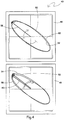
- FIG. 4 displays the elliptical trace of a so-called flat screen unit, similar to that depicted in FIG. 1 .
- Plotted data are provided for the discharge end 26 and for the feed end 24.
- Discharge plots 50, 52 monitoring movement in two-dimensions (x and y-axes) are displayed for corresponding discharge end monitoring points 44a, 44b on each plate 12, 14.
- feed plots 54, 56 are displayed for monitoring similar motion at corresponding feed end monitoring points 44c, 44d.
- the plots 50, 52, and 54, 56 are displayed in superimposed fashion.
- the data may be displayed in the form of the plots 50-56, and/or as calculated linear relationships, 58, 60. If the plates 12, 14 are operating out of synch, the plots will show areas of disparity 62. These areas 62 are the graphical representation of the operational stress being experienced by the unit 10 and being monitored by the system 40. Depending on the unit 10 and the particular circumstances, a certain amount of disparity between the plates 12, 14 may be acceptable. However, disparities beyond a designated threshold indicate that modifications to the unit 10 are in order to obtain more efficient production and to prolong the operational life of the unit. In FIG. 4 , the discharge plots 50, 52 are determined to be in synch, while the feed plots 54, 56 have an excessive amount of disparity 62.
- FIG. 5 an exemplary display of eight monitoring points in two directions (x and y-axes) is shown for a so-called banana screen, having sloping arcuate decks as known in the art.
- Such screen units generate straight line discharge plots 64, 66 at a first discharge monitoring point 44, and discharge plots 68, 70 at a second discharge monitoring point.
- feed plots 72, 74 are taken at a first feed monitoring point 44 and plots 76, 78 at a second feed monitoring point. It will be seen that the discharge plots, 64-70 are in synch, while one set of feed plots 72, 74 are out of synch, having an excessive amount of disparity 62.
- An advantage of the present system 40 is that the monitoring of the various points 44 is performed simultaneously and the data is visible in real time, so that plate-to-plate variations can be determined more objectively and accurately under actual operating conditions than using conventional techniques.
- FIG. 6 a schematic display plot of the 'x' and 'z' axes is depicted, where in curve 'a' the machine is in alignment, while in curve 'b', the machine is out of alignment.
- a data network suitable for collecting and analyzing data from units 10 through the system 40 is generally designated 80.
- the data generated by all of the monitoring points 44 of a particular unit is collected at a screen station 82 which is preferably a terminal box to which are connected the leads of each accelerometer. If there are multiple units 10 at a particular screening facility, multiple screen stations 82 are provided.
- Each screen station 82 is connected via typical network connections 84, either hard wired or broadband wireless as known in the art using a firewall 86 preferably of the VPN type (shown schematically).
- a central processing unit 88 is provided at a user's facility, and/or data may is optionally transmitted to similar processors 90 at a dealer and/or manufacturer facility, via telephone lines, wirelessly as known in the art. Thus operators and/or manufacturers are able to monitor unit performance in real time from multiple points on each unit.
Landscapes
- Physics & Mathematics (AREA)
- General Physics & Mathematics (AREA)
- Testing Of Devices, Machine Parts, Or Other Structures Thereof (AREA)
- Measurement Of Mechanical Vibrations Or Ultrasonic Waves (AREA)
Description
- The present invention relates generally to vibrating equipment used for material processing, such as vibrator screen units used for separating or classifying particulate feed material as to size, and more particularly to a system for facilitating the designing, building and maintenance of such screen units by monitoring operational stress forces.
- Vibrator screen units are well known for separating particulate feed material into various size classes.
US 2006/243643 A1 for example discloses a vibratory separator or shaker wherein an acceleration sensor is used to enhance and/or optimize the performance of said vibratory separator or shaker. Such units include a pair of separated, generally vertical sidewalls or plates which support at least one and preferably several transversely positioned decks of apertured screening material. When multiple screening decks are provided, the upper screen materials have larger openings than those below. Upon generation of a generally vertical vibrating motion, particles fed to the decks are caused to bounce so that smaller-sized particles fall through the openings in the screen material, and larger-sized particles remain upon the deck. Using multiple decks, operators are able to generate a product of classified material in several size ranges. - Such screen units are designed with a specified amplitude and velocity, which is a function of the configuration of the plates, the size and type of the vibration generating device, the orientation of the plates and/or the screen decks, and fabrication and assembly techniques, among other factors well known in the art of designing and manufacturing such units. As a result, screen units of a particular model typically develop a fairly predictable system frequency upon operation, with individual units of a particular design developing small variations in system frequency from the model/design parameters. Over time, the system frequency of an individual unit often changes, influencing longevity and productivity. Designers attempt to design vibrating units so that they operate as far from the system frequency as practical while still maintaining desired production rates.
- In the designing of such units, it is desired that the plates move synchronously, so that the screen decks are vibrated uniformly across the length of the deck. This synchrony not only enhances the classifying performance of the unit, it also prolongs operational life of the screen unit. When plates are not in synch, operationally-generated forces cause stress, among other places to attachment joints between the screen decks and the plates, and between the plates and laterally projecting spring mounts. Imbalanced units have shorter operational lives, require more frequent maintenance, and/or have less efficient classification performance.
- Conventional vibrating screen units are provided with plates made of steel in the range of 7.9 to 19.1 mm (.3125 to .75 inch) thick, which is strong in the axial direction. However, the plates are relatively thin in view of the production loads and work performed, and are susceptible to racking or twisting forces along the z-axis. Potentially damaging operational forces in vibrator screen units are caused, among other factors, by uneven or misaligned springs, uneven foundation mounts, improper vibrating speed, improperly installed screen decks, worn bushings and/or imbalanced flywheels on the vibration generator. Due to the wide variety of potential causes for vibrator unit malfunction, it is difficult for the average operator to detect when a unit is not operating according to its design parameters. It is even more difficult for the average operator to accurately diagnose the cause of the malfunction.
- Conventional techniques for monitoring plate movement include the fastening of paper throw cards to the plates at designated locations, typically near the inlet and discharge ends of the unit, and near the vibration generator. Ideally the cards are mounted at corresponding locations on each plate at a corresponding end of the unit. However, due to the harsh operational environment of the vibrator unit (quarry, mine, gravel plant, road building site, etc.) and the variations in operator training, very often the cards on each plate at a designated machine are not properly placed for accurate results. An individual applies a pencil or similar marking instrument while attempting to hold his hands steady against the card while the unit is operating, and a pattern is generated by the unit, which varies by the style of unit involved. Typical patterns include ellipses, straight lines and circles. Upon drawing at least one trace or curve, or preferably a series of traces at one monitoring point, the user then moves to a corresponding card at another monitoring point on the machine and produces another trace or set of traces. Next, the traces of the respective plates at the same location are visually compared as to their two-dimensional (x and y-axes) similarity. If the patterns are angularly skewed, show blurred lines or are vertically or horizontally displaced beyond a designated range, the unit is judged to be out of synch, requiring modification of the plates or screen deck fasteners, change of speed of the vibration generating device or the device itself, or other modifications known to skilled practitioners to bring the traced patterns within acceptable degrees of similarity.
- While the use of throw cards is the accepted technique for monitoring the operation of vibrator units, a significant drawback of this technique is that it is subjective, one cause being that the pressure applied by individuals varies, influencing the results. Some operators are anxious about standing next to the unit vibrating in the range of 900 rpm. As a result, the pressure applied by the user may vary, as well as the angle of the pencil to the throw card. Further, if the operator's hand moves while marking on the card, or if he shifts his weight or moves his feet, the results will vary. Such variation may apply on a card-to-card basis by a single operator, due to fatigue or subtle variations in stance or pressure at various points on the machine, and such variations increase when operator-to-operator technique is compared. On large-sized vibrator units, some points on the machine are too high to reach when standing, and due to instability, ladders are not placed against vibrating machines. Thus, on larger units, some technically desired sampling points are not practically monitorable and are virtually inaccessible.
- To combat this variation on units where access is available, it is recommended that the same individual monitors each plate at each designated point on a particular vibrator unit at a sampling event. Due to this procedure, since the same individual can only monitor one location at a time, the sampling is temporally displaced for each monitoring point on respective plates. Even when the same individual performs the monitoring on a designated unit, the other variables listed above typically combine to create a great degree of subjectivity in the curves or plots generated. As such, many operators rely on specially trained vibrator unit technicians who periodically monitor the units for performance. Such technicians are trained to avoid the above-listed variables in card throw techniques; however while more accurate than average, their throw card data is still somewhat subjective. Also, as may be appreciated, there is limited availability of such technicians, who are also trained to diagnose the causes of substandard throw card curves or plots and their remedies.
- Another drawback of the conventional throw card technique is that the monitoring is two-dimensional only, in the x and y-axes. Other than when a portion of a drawn curve is missing in one location or portion, indicating lateral motion of the unit, this conventional technique is incapable of accurately monitoring side-to-side (z-axis) movement of the unit. Such movement is an important indicator of plate asynchrony, due to the susceptibility of the plates to damage or accelerated wear caused by imbalanced forces acting in this direction. In view of the many causes for variation, it is estimated that as much as 70-80% of conventional throw card data is suspect.
- In an effort to objectify the monitoring of plate movement using throw cards, some vibrator unit technicians have explored the use of accelerometers placed at desired unit monitoring locations. The accelerometers are positioned to monitor movement in the x and y-axes in similar locations to the placement of throw cards, and are electrically connected to a hand held device which plots appropriate curves. On a typical screen unit, pairs of accelerometers are placed at respective corners of the unit. Accelerometers have also been placed to monitor the bearing condition of the vibration generator. However, while this technique generates more objective data, conventional monitoring equipment has been designed to monitor data from one point on one plate at a time, and comparisons are typically restricted to a two-dimensional format (x and y-axes). While the implementation of accelerometers as discussed above shows promise in obtaining more objective and reliable vibrator unit performance data, the performance of vibrator screen units is very dynamic, and changes constantly with the volume and or type of material being screened. Thus, even the above-described technique involves inherent variability.
- Thus, there is a need for an improved system for monitoring vibrator screen unit operation on a plate-by-plate basis to obtain more accurate data, even on larger vibrator units. There is also a need for an improved system for monitoring operational stresses on vibrator screen units which accounts for the dynamic nature of machine operation.
- The above-described needs are met or exceeded by the present stress monitoring system for vibrator screen units. Features of the present system include simultaneous or real-time monitoring of both plates at designated points. By providing simultaneous monitoring, dynamic changes in operation are accounted for. Also, plate-to-plate performance variations are more accurately measured. Another feature of the present system is that simultaneous monitoring is provided at each plate in the z-axis to monitor side-to-side machine movement often indicative of asynchronous or imbalanced operation. The present system provides superimposed plate-to-plate performance curves so that performance curve variations are more readily observed and compared with designated acceptable variations. Also, data from monitored machines is available for remote monitoring by operators and/or machine manufacturers or dealers. As a unit ages, monitoring continues so that adjustments to the unit are made to stay clear of the changing system frequencies.
- More specifically, in accordance with an aspect of the invention there is provided a stress monitoring system as defined by claim 1 of the appended claims..
-
-
FIG. 1 is a front perspective view of a vibrator screen unit suitable for use with the present monitoring system; -
FIG. 2 is a schematic example of conventional throw curve data from a single location on a vibrator unit; -
FIG. 3 is a schematic front perspective view of a suitable vibrator screen unit equipped with sensors used in the present system; -
FIG. 4 is a schematic representation of data display overlays from simultaneous monitoring of various points on a designated vibrator screen unit; -
FIG. 5 is a schematic representation of data display overlays from simultaneous monitoring of various points on a second type of designated vibrator screen unit; -
FIG. 6 is a schematic representation of data display of vibrator performance in the x and z-axes; and -
FIG. 7 is a schematic representation of a computerized machine monitoring network employing the present stress testing system. - Referring now to
FIG. 1 , a vibrating unit of the type suitable for use with the present system is generally designated 10 and is depicted as a vibrator screen unit. As is well known in the art, thevibrator unit 10 includes a first sidewall orplate 12 and a second sidewall orplate 14 disposed in spaced, parallel orientation to the first plate and being separated by at least one transversely disposedscreen deck 16. Mostsuch units 10 are provided with multiple screen decks, here depicted as second andthird decks uppermost screen deck 16 has a relatively coarser mesh screen fabric (not shown) or larger apertures. Progressing toward thethird deck 20, the mesh pattern becomes finer for retaining relatively smaller particles. The selection of mesh sizes for thedecks tubes 22 are attached to inside walls of eachplate screen decks - The
unit 10 has afeed end 24 and adischarge end 26, with the feed end sometimes being disposed at a higher elevation than the discharge end to promote gravity flow of classified particulate material. At least one coiledcompressible spring 28 is located adjacent the corresponding feed and discharge ends 24, 26 of eachplate unit 10. Thesprings 28 are typically provided in clusters of at least two and are disposed between upper mounting points orflanges 30 affixed to the correspondingplates unit 10 is resiliently mounted to the substrate. A motion generator, such as a powered flywheel, eccentric or the like is designated 34 and generates a cyclical movement of theunit 10 upon energization. Depending upon the type and construction of theunit 10, the movement created by themotion generator 34 causes theunit 10 to define a linear, elliptical or circular cyclical movement. - Given the relatively narrow spacing of the
plates unit 10, and the transverse support bars 22 being the main structural support of the unit, it will be understood that the unit is subject to vertical and/or horizontal racking or torque forces upon stress loading, particularly when large-sized and/or large volumes of particulate feed material are deposited upon theuppermost deck 16. The operational life of theunit 10 is in part a function of the degree of misalignment or disparity in movement between theplates - Referring now to
FIG. 2 , conventional throw card data is provided for a relatively small-sized flat screen-type vibrator unit similar to that depicted inFIG. 1 . Variations are seen in the operator's application of pressure against the card, and movement of the operator or operator's hands during plotting. Variations across a lateral row of curves are readily seen. Curve 'a' shows the ellipses laterally skewed, indicating hand movement or also imbalanced machine springs. Curve 'b', taken on the same machine within seconds of the curve 'a', depicts relatively balanced operation, albeit at a reduced throw, since the length of the ellipse is indicative of machine throw. Curves 'c'-'f depict similar variations. Curves 'g', 'h' and 'i' depict light operator hand pressure and/or hand movement, or are indicative of machine imbalance in the 'z' axis causing lateral cyclical movement. - Comparison of two such cards taken at each
plate - Referring now to
FIGs. 1 and3 , the present stress monitoring system is generally designated 40 and includes at least onemotion sensor 42, preferably an accelerometer; however other motion sensors are contemplated, disposed at at least onemonitoring point 44 on theunit 10. Preferably, the monitoring points 44 are identical corresponding locations on each of theplates motion sensor 42 is provided, it is preferred that at least two such sensors are disposed at eachmonitoring point 44 to monitor the x and y-orthogonal axes, and most preferably three such sensors are disposed at eachmonitoring point 44 to respectively measure movement in the x, y and z-axes. Thus, in apreferred system 40 there are at least eight and preferably twelvetotal sensors 42. - The
sensors 42 are connected to a processor 46 (FIG. 7 ) such as a computer, server or similar unit capable of receiving, manipulating and transmitting data. Suitable software is available from Metso Automation (www.metsoautomation.com) under the designation Sensodec™. In the preferred embodiment, theprocessor 46 is provided with adisplay 48 for providing visually detectable performance curves of theunit 10 at the monitoring points 44 such that simultaneous monitoring data of the monitoring points is provided to the processor for comparing real-time movement of the corresponding monitoring points on the opposed plates. - Referring now to
FIG. 4 , using conventional software, data generated by thesensors 42 is converted by theprocessor 46 into curves or plots representing unit motion that are plotted on the display.FIG. 4 displays the elliptical trace of a so-called flat screen unit, similar to that depicted inFIG. 1 . Plotted data are provided for thedischarge end 26 and for thefeed end 24. Discharge plots 50, 52 monitoring movement in two-dimensions (x and y-axes) are displayed for corresponding discharge end monitoring points 44a, 44b on eachplate plots - To enable the operator to determine whether the
unit 10 is operating properly, theplots plates disparity 62. Theseareas 62 are the graphical representation of the operational stress being experienced by theunit 10 and being monitored by thesystem 40. Depending on theunit 10 and the particular circumstances, a certain amount of disparity between theplates unit 10 are in order to obtain more efficient production and to prolong the operational life of the unit. InFIG. 4 , the discharge plots 50, 52 are determined to be in synch, while the feed plots 54, 56 have an excessive amount ofdisparity 62. - Referring now to
FIG. 5 , an exemplary display of eight monitoring points in two directions (x and y-axes) is shown for a so-called banana screen, having sloping arcuate decks as known in the art. Such screen units generate straight line discharge plots 64, 66 at a firstdischarge monitoring point 44, and dischargeplots plots feed monitoring point 44 andplots disparity 62. It will be appreciated that the amount ofdisparity 62 will vary with the application and the specific machine. An advantage of thepresent system 40 is that the monitoring of thevarious points 44 is performed simultaneously and the data is visible in real time, so that plate-to-plate variations can be determined more objectively and accurately under actual operating conditions than using conventional techniques. - Referring now to
FIG. 6 , a schematic display plot of the 'x' and 'z' axes is depicted, where in curve 'a' the machine is in alignment, while in curve 'b', the machine is out of alignment. - Referring now to
FIG. 7 , a data network suitable for collecting and analyzing data fromunits 10 through thesystem 40 is generally designated 80. The data generated by all of the monitoring points 44 of a particular unit is collected at ascreen station 82 which is preferably a terminal box to which are connected the leads of each accelerometer. If there aremultiple units 10 at a particular screening facility,multiple screen stations 82 are provided. Eachscreen station 82 is connected viatypical network connections 84, either hard wired or broadband wireless as known in the art using afirewall 86 preferably of the VPN type (shown schematically). Acentral processing unit 88 is provided at a user's facility, and/or data may is optionally transmitted tosimilar processors 90 at a dealer and/or manufacturer facility, via telephone lines, wirelessly as known in the art. Thus operators and/or manufacturers are able to monitor unit performance in real time from multiple points on each unit. - While specific embodiments of the present stress monitoring system for vibrator screens have been shown and described, it will be appreciated by those skilled in the art that changes and modifications may be made thereto without departing from the invention as set forth in the following claims.
Claims (13)
- A stress monitoring system comprising:a vibrator screen unit (10) having first and second opposed sidewall plates (12, 14) with at least one screen deck (16, 18) transversely mounted therebetween, and:at least one motion sensor (42) disposed at corresponding monitoring points (44) on each of said first and second plates (12, 14);
said motion sensors being connected to a processor (46) such that simultaneous monitoring data of said monitoring points is provided to said processor for comparing real-time movement of the corresponding monitoring points of said opposed plates. - The system of claim 1 wherein each said motion sensor (42) is provided for monitoring movement in a respective one of a set of orthogonal axes, and each said monitoring point is provided with two such sensors, corresponding to the x and y-axes defined by the length and width of the second sidewall plate (14) respectively.
- The system of claim 1 wherein each said motion sensor (42) is provided for monitoring movement in a respective one of a set of orthogonal axis, and each said monitoring point is provided with three such sensors, corresponding to the x, y and z-axes, the x and y-axes defined by the length and width of the second sidewall plate (14) respectively, and the z-axis orthogonal to the x and y-axes.
- The system of claim 1 wherein said processor (46) is provided with a display (48) and said data from each monitoring point is provided in superimposed fashion for visually monitoring discrepancies between said plates.
- The system of claim 1 wherein said at least one motion sensor (42) is an accelerometer.
- The system of claim 1 further including providing a machine monitoring network (80), with said processor (46) connected to said network.
- The system of claim 1 further including multiple sensors (42) located at each said monitoring point (44) for monitoring motion in x, y and z-axes , the x and y-axes defined by the length and width of the second sidewall plate (14) respectively, and the z-axis orthogonal to the x and y-axes.
- The system of claim 7 wherein said sensors (42) are accelerometers.
- The system of claim 8 wherein a display (48) is configured to display data from each said monitoring point (44) in superimposed fashion for visually monitoring discrepancies between said plates.
- The system of claim 1 wherein each of the monitoring points includes two motion sensors (42) configured to monitor movement in two different axes that are orthogonal to each other.
- The system of claim 1 wherein each of the monitoring points includes three motion sensors (42) configured to monitor movement in three different axes that are orthogonal to each other.
- The system of claims 1 or 10 or 11 further comprising a display configured to display data from the motion sensors at each of said monitoring points in a superimposed fashion for visually monitoring discrepancies between said plates.
- The system of claim 1 or 10 or 11 wherein the motion sensors are accelorometers.
Applications Claiming Priority (2)
| Application Number | Priority Date | Filing Date | Title |
|---|---|---|---|
| US11/821,973 US7614306B2 (en) | 2007-06-26 | 2007-06-26 | Stress monitoring system for vibrator screen units |
| PCT/US2008/062008 WO2009002606A1 (en) | 2007-06-26 | 2008-04-30 | Stress monitoring system for vibrator screen units |
Publications (3)
| Publication Number | Publication Date |
|---|---|
| EP2162240A1 EP2162240A1 (en) | 2010-03-17 |
| EP2162240A4 EP2162240A4 (en) | 2017-07-05 |
| EP2162240B1 true EP2162240B1 (en) | 2021-03-10 |
Family
ID=40158854
Family Applications (1)
| Application Number | Title | Priority Date | Filing Date |
|---|---|---|---|
| EP08747182.7A Active EP2162240B1 (en) | 2007-06-26 | 2008-04-30 | Stress monitoring system for vibrator screen units |
Country Status (8)
| Country | Link |
|---|---|
| US (1) | US7614306B2 (en) |
| EP (1) | EP2162240B1 (en) |
| CN (1) | CN101711189B (en) |
| AU (1) | AU2008268985B2 (en) |
| BR (1) | BRPI0811323B1 (en) |
| CA (1) | CA2691244C (en) |
| CL (1) | CL2008000837A1 (en) |
| WO (1) | WO2009002606A1 (en) |
Cited By (1)
| Publication number | Priority date | Publication date | Assignee | Title |
|---|---|---|---|---|
| WO2025256969A1 (en) * | 2024-06-11 | 2025-12-18 | Revibe Energy Ab | Synchronized multi-node system for monitoring of a machine |
Families Citing this family (11)
| Publication number | Priority date | Publication date | Assignee | Title |
|---|---|---|---|---|
| US20100206782A1 (en) * | 2009-02-17 | 2010-08-19 | Metso Minerals Industries, Inc. | Cone lip assembly |
| JP5838986B2 (en) * | 2013-03-25 | 2016-01-06 | Jfeスチール株式会社 | Operation control method of vibration sieve device |
| DE102014001515A1 (en) * | 2014-02-07 | 2015-08-13 | Schenck Process Gmbh | vibrating machine |
| CN104984903B (en) * | 2015-07-31 | 2017-02-08 | 南安市永腾技术咨询有限公司 | Powder vibrating screen used for ore extraction |
| GB2571941B (en) * | 2018-03-13 | 2021-01-13 | Weir Minerals Africa Pty Limited | Vibration screen sensing mechanism and monitoring system |
| JP7367330B2 (en) * | 2019-04-12 | 2023-10-24 | 株式会社サタケ | Operation monitoring system for sieving equipment |
| WO2020209361A1 (en) * | 2019-04-12 | 2020-10-15 | 株式会社サタケ | Operation monitoring system for sieving device |
| KR20210144894A (en) | 2019-04-12 | 2021-11-30 | 가부시끼가이샤 사따께 | sieving device |
| CN112774968A (en) * | 2020-12-22 | 2021-05-11 | 临沂矿业集团有限责任公司 | Multifunctional screening device for coal mine |
| CN114563204B (en) * | 2022-03-25 | 2024-06-07 | 江苏大学 | Quality reliability test bench and test method for cleaning screening box |
| US11867585B2 (en) * | 2022-06-02 | 2024-01-09 | Metso Outotec USA Inc. | System and method of monitoring the operation of vibrating equipment |
Citations (1)
| Publication number | Priority date | Publication date | Assignee | Title |
|---|---|---|---|---|
| WO1993010448A1 (en) * | 1991-11-12 | 1993-05-27 | Vibra-Metrics, Inc. | Method and apparatus for monitoring multiple points on a vibrating structure |
Family Cites Families (9)
| Publication number | Priority date | Publication date | Assignee | Title |
|---|---|---|---|---|
| US4300383A (en) * | 1979-08-27 | 1981-11-17 | Wallace Murray Corporation | Crankshaft damper resonance monitor |
| TW227601B (en) * | 1993-01-25 | 1994-08-01 | Gen Electric | |
| US5614094A (en) | 1994-05-13 | 1997-03-25 | Deister Machine Co., Inc. | Vibrating screen unit |
| WO1996037765A1 (en) * | 1995-05-22 | 1996-11-28 | Analog Devices, Inc. | Integrated accelerometer test system |
| DE10113038C2 (en) * | 2001-03-17 | 2003-04-10 | Aloys Wobben | Tower vibration monitoring |
| CN1361480A (en) * | 2002-01-18 | 2002-07-31 | 武汉武水电力有限公司 | Vibration throw parameter monitoring and analyzing method for water power set |
| US6680591B1 (en) * | 2002-11-01 | 2004-01-20 | General Kinematics Corporation | Apparatus for phase angle monitoring of a plurality of vibrating machines |
| US7571817B2 (en) * | 2002-11-06 | 2009-08-11 | Varco I/P, Inc. | Automatic separator or shaker with electromagnetic vibrator apparatus |
| US7025210B2 (en) | 2003-04-17 | 2006-04-11 | Derrick Manufacturing Corporation | Method and apparatus for attenuating sound from vibratory screening machines |
-
2007
- 2007-06-26 US US11/821,973 patent/US7614306B2/en active Active
-
2008
- 2008-03-24 CL CL2008000837A patent/CL2008000837A1/en unknown
- 2008-04-30 EP EP08747182.7A patent/EP2162240B1/en active Active
- 2008-04-30 AU AU2008268985A patent/AU2008268985B2/en active Active
- 2008-04-30 CN CN2008800215326A patent/CN101711189B/en active Active
- 2008-04-30 CA CA2691244A patent/CA2691244C/en active Active
- 2008-04-30 BR BRPI0811323-8A patent/BRPI0811323B1/en active IP Right Grant
- 2008-04-30 WO PCT/US2008/062008 patent/WO2009002606A1/en not_active Ceased
Patent Citations (1)
| Publication number | Priority date | Publication date | Assignee | Title |
|---|---|---|---|---|
| WO1993010448A1 (en) * | 1991-11-12 | 1993-05-27 | Vibra-Metrics, Inc. | Method and apparatus for monitoring multiple points on a vibrating structure |
Cited By (1)
| Publication number | Priority date | Publication date | Assignee | Title |
|---|---|---|---|---|
| WO2025256969A1 (en) * | 2024-06-11 | 2025-12-18 | Revibe Energy Ab | Synchronized multi-node system for monitoring of a machine |
Also Published As
| Publication number | Publication date |
|---|---|
| US7614306B2 (en) | 2009-11-10 |
| WO2009002606A1 (en) | 2008-12-31 |
| HK1144081A1 (en) | 2011-01-28 |
| CN101711189B (en) | 2013-07-10 |
| EP2162240A4 (en) | 2017-07-05 |
| CA2691244A1 (en) | 2008-12-31 |
| EP2162240A1 (en) | 2010-03-17 |
| CN101711189A (en) | 2010-05-19 |
| CA2691244C (en) | 2012-04-17 |
| BRPI0811323B1 (en) | 2019-07-02 |
| US20090000384A1 (en) | 2009-01-01 |
| CL2008000837A1 (en) | 2009-01-02 |
| AU2008268985B2 (en) | 2012-02-02 |
| BRPI0811323A2 (en) | 2014-10-21 |
| AU2008268985A1 (en) | 2008-12-31 |
Similar Documents
| Publication | Publication Date | Title |
|---|---|---|
| CA2691244C (en) | Stress monitoring system for vibrator screen units | |
| US10654072B2 (en) | Variable slope 3-shaft vibrating mechanism | |
| EP3102920B1 (en) | Vibration machine | |
| DE102017009373B3 (en) | Mobile device for detecting the state and operating parameters of vibrating machines, equipped vibrating machine and method for detecting the operating and state parameters of vibrating machines | |
| EP3735324B1 (en) | Vibrating screen monitoring system and method | |
| CN113661016B (en) | Screening device | |
| CN116419896A (en) | Method for Estimating Cumulative Damage and Fatigue Strength of Vibrating Machines | |
| US20090248360A1 (en) | Method and system for machine condition monitoring and reporting | |
| CN220479472U (en) | Systems for monitoring the operation of vibrating equipment and vibrating equipment used to move materials | |
| EP4545917A1 (en) | Vibration monitoring system | |
| HK1144081B (en) | Stress monitoring system for vibrator screen units | |
| JP7331427B2 (en) | sieving device | |
| JP7263894B2 (en) | sieving device | |
| US20250360540A1 (en) | Vibration monitoring and visualisation system | |
| GB2624187A (en) | Monitoring system for vibrating apparatus |
Legal Events
| Date | Code | Title | Description |
|---|---|---|---|
| PUAI | Public reference made under article 153(3) epc to a published international application that has entered the european phase |
Free format text: ORIGINAL CODE: 0009012 |
|
| 17P | Request for examination filed |
Effective date: 20091221 |
|
| AK | Designated contracting states |
Kind code of ref document: A1 Designated state(s): AT BE BG CH CY CZ DE DK EE ES FI FR GB GR HR HU IE IS IT LI LT LU LV MC MT NL NO PL PT RO SE SI SK TR |
|
| AX | Request for extension of the european patent |
Extension state: AL BA MK RS |
|
| RIN1 | Information on inventor provided before grant (corrected) |
Inventor name: KUEHL, RONALD, D., II |
|
| DAX | Request for extension of the european patent (deleted) | ||
| RA4 | Supplementary search report drawn up and despatched (corrected) |
Effective date: 20170606 |
|
| RIC1 | Information provided on ipc code assigned before grant |
Ipc: G01M 7/00 20060101ALI20170530BHEP Ipc: B07B 1/28 20060101AFI20170530BHEP Ipc: G01H 1/00 20060101ALI20170530BHEP |
|
| STAA | Information on the status of an ep patent application or granted ep patent |
Free format text: STATUS: EXAMINATION IS IN PROGRESS |
|
| 17Q | First examination report despatched |
Effective date: 20190731 |
|
| REG | Reference to a national code |
Ref country code: DE Ref legal event code: R079 Ref document number: 602008063765 Country of ref document: DE Free format text: PREVIOUS MAIN CLASS: B07B0001280000 Ipc: G01H0001000000 |
|
| RIC1 | Information provided on ipc code assigned before grant |
Ipc: B07B 1/42 20060101ALI20200731BHEP Ipc: G01M 99/00 20110101ALN20200731BHEP Ipc: B07B 13/18 20060101ALI20200731BHEP Ipc: G01H 1/00 20060101AFI20200731BHEP |
|
| GRAP | Despatch of communication of intention to grant a patent |
Free format text: ORIGINAL CODE: EPIDOSNIGR1 |
|
| STAA | Information on the status of an ep patent application or granted ep patent |
Free format text: STATUS: GRANT OF PATENT IS INTENDED |
|
| RIC1 | Information provided on ipc code assigned before grant |
Ipc: G01H 1/00 20060101AFI20200831BHEP Ipc: B07B 13/18 20060101ALI20200831BHEP Ipc: G01M 99/00 20110101ALN20200831BHEP Ipc: B07B 1/42 20060101ALI20200831BHEP |
|
| INTG | Intention to grant announced |
Effective date: 20200929 |
|
| GRAS | Grant fee paid |
Free format text: ORIGINAL CODE: EPIDOSNIGR3 |
|
| GRAA | (expected) grant |
Free format text: ORIGINAL CODE: 0009210 |
|
| STAA | Information on the status of an ep patent application or granted ep patent |
Free format text: STATUS: THE PATENT HAS BEEN GRANTED |
|
| AK | Designated contracting states |
Kind code of ref document: B1 Designated state(s): AT BE BG CH CY CZ DE DK EE ES FI FR GB GR HR HU IE IS IT LI LT LU LV MC MT NL NO PL PT RO SE SI SK TR |
|
| REG | Reference to a national code |
Ref country code: GB Ref legal event code: FG4D |
|
| REG | Reference to a national code |
Ref country code: AT Ref legal event code: REF Ref document number: 1370335 Country of ref document: AT Kind code of ref document: T Effective date: 20210315 Ref country code: CH Ref legal event code: EP |
|
| REG | Reference to a national code |
Ref country code: SE Ref legal event code: TRGR |
|
| REG | Reference to a national code |
Ref country code: IE Ref legal event code: FG4D |
|
| REG | Reference to a national code |
Ref country code: DE Ref legal event code: R096 Ref document number: 602008063765 Country of ref document: DE |
|
| REG | Reference to a national code |
Ref country code: FI Ref legal event code: FGE |
|
| REG | Reference to a national code |
Ref country code: DE Ref legal event code: R082 Ref document number: 602008063765 Country of ref document: DE Representative=s name: DEHMEL & BETTENHAUSEN PATENTANWAELTE PARTMBB, DE Ref country code: DE Ref legal event code: R081 Ref document number: 602008063765 Country of ref document: DE Owner name: METSO OUTOTEC USA INC., WAUKESHA, US Free format text: FORMER OWNER: METSO MINERALS INDUSTRIES, INC., WAUKESHA, WIS., US Ref country code: DE Ref legal event code: R081 Ref document number: 602008063765 Country of ref document: DE Owner name: METSO FINLAND OY, FI Free format text: FORMER OWNER: METSO MINERALS INDUSTRIES, INC., WAUKESHA, WIS., US Ref country code: DE Ref legal event code: R081 Ref document number: 602008063765 Country of ref document: DE Owner name: METSO OUTOTEC FINLAND OY, FI Free format text: FORMER OWNER: METSO MINERALS INDUSTRIES, INC., WAUKESHA, WIS., US |
|
| REG | Reference to a national code |
Ref country code: NO Ref legal event code: T2 Effective date: 20210310 |
|
| REG | Reference to a national code |
Ref country code: NO Ref legal event code: CREP Representative=s name: BRYN AARFLOT AS, STORTINGSGATA 8, 0161 OSLO, NORGE |
|
| RAP2 | Party data changed (patent owner data changed or rights of a patent transferred) |
Owner name: METSO OUTOTEC USA INC. |
|
| REG | Reference to a national code |
Ref country code: LT Ref legal event code: MG9D |
|
| PG25 | Lapsed in a contracting state [announced via postgrant information from national office to epo] |
Ref country code: GR Free format text: LAPSE BECAUSE OF FAILURE TO SUBMIT A TRANSLATION OF THE DESCRIPTION OR TO PAY THE FEE WITHIN THE PRESCRIBED TIME-LIMIT Effective date: 20210611 Ref country code: HR Free format text: LAPSE BECAUSE OF FAILURE TO SUBMIT A TRANSLATION OF THE DESCRIPTION OR TO PAY THE FEE WITHIN THE PRESCRIBED TIME-LIMIT Effective date: 20210310 Ref country code: LT Free format text: LAPSE BECAUSE OF FAILURE TO SUBMIT A TRANSLATION OF THE DESCRIPTION OR TO PAY THE FEE WITHIN THE PRESCRIBED TIME-LIMIT Effective date: 20210310 Ref country code: BG Free format text: LAPSE BECAUSE OF FAILURE TO SUBMIT A TRANSLATION OF THE DESCRIPTION OR TO PAY THE FEE WITHIN THE PRESCRIBED TIME-LIMIT Effective date: 20210610 |
|
| REG | Reference to a national code |
Ref country code: AT Ref legal event code: MK05 Ref document number: 1370335 Country of ref document: AT Kind code of ref document: T Effective date: 20210310 |
|
| REG | Reference to a national code |
Ref country code: NL Ref legal event code: MP Effective date: 20210310 |
|
| PG25 | Lapsed in a contracting state [announced via postgrant information from national office to epo] |
Ref country code: LV Free format text: LAPSE BECAUSE OF FAILURE TO SUBMIT A TRANSLATION OF THE DESCRIPTION OR TO PAY THE FEE WITHIN THE PRESCRIBED TIME-LIMIT Effective date: 20210310 |
|
| PG25 | Lapsed in a contracting state [announced via postgrant information from national office to epo] |
Ref country code: NL Free format text: LAPSE BECAUSE OF FAILURE TO SUBMIT A TRANSLATION OF THE DESCRIPTION OR TO PAY THE FEE WITHIN THE PRESCRIBED TIME-LIMIT Effective date: 20210310 |
|
| PG25 | Lapsed in a contracting state [announced via postgrant information from national office to epo] |
Ref country code: AT Free format text: LAPSE BECAUSE OF FAILURE TO SUBMIT A TRANSLATION OF THE DESCRIPTION OR TO PAY THE FEE WITHIN THE PRESCRIBED TIME-LIMIT Effective date: 20210310 Ref country code: CZ Free format text: LAPSE BECAUSE OF FAILURE TO SUBMIT A TRANSLATION OF THE DESCRIPTION OR TO PAY THE FEE WITHIN THE PRESCRIBED TIME-LIMIT Effective date: 20210310 Ref country code: EE Free format text: LAPSE BECAUSE OF FAILURE TO SUBMIT A TRANSLATION OF THE DESCRIPTION OR TO PAY THE FEE WITHIN THE PRESCRIBED TIME-LIMIT Effective date: 20210310 |
|
| PG25 | Lapsed in a contracting state [announced via postgrant information from national office to epo] |
Ref country code: RO Free format text: LAPSE BECAUSE OF FAILURE TO SUBMIT A TRANSLATION OF THE DESCRIPTION OR TO PAY THE FEE WITHIN THE PRESCRIBED TIME-LIMIT Effective date: 20210310 Ref country code: IS Free format text: LAPSE BECAUSE OF FAILURE TO SUBMIT A TRANSLATION OF THE DESCRIPTION OR TO PAY THE FEE WITHIN THE PRESCRIBED TIME-LIMIT Effective date: 20210710 Ref country code: SK Free format text: LAPSE BECAUSE OF FAILURE TO SUBMIT A TRANSLATION OF THE DESCRIPTION OR TO PAY THE FEE WITHIN THE PRESCRIBED TIME-LIMIT Effective date: 20210310 Ref country code: PL Free format text: LAPSE BECAUSE OF FAILURE TO SUBMIT A TRANSLATION OF THE DESCRIPTION OR TO PAY THE FEE WITHIN THE PRESCRIBED TIME-LIMIT Effective date: 20210310 Ref country code: PT Free format text: LAPSE BECAUSE OF FAILURE TO SUBMIT A TRANSLATION OF THE DESCRIPTION OR TO PAY THE FEE WITHIN THE PRESCRIBED TIME-LIMIT Effective date: 20210712 Ref country code: ES Free format text: LAPSE BECAUSE OF FAILURE TO SUBMIT A TRANSLATION OF THE DESCRIPTION OR TO PAY THE FEE WITHIN THE PRESCRIBED TIME-LIMIT Effective date: 20210310 |
|
| REG | Reference to a national code |
Ref country code: DE Ref legal event code: R097 Ref document number: 602008063765 Country of ref document: DE |
|
| PG25 | Lapsed in a contracting state [announced via postgrant information from national office to epo] |
Ref country code: LU Free format text: LAPSE BECAUSE OF NON-PAYMENT OF DUE FEES Effective date: 20210430 |
|
| PLBE | No opposition filed within time limit |
Free format text: ORIGINAL CODE: 0009261 |
|
| STAA | Information on the status of an ep patent application or granted ep patent |
Free format text: STATUS: NO OPPOSITION FILED WITHIN TIME LIMIT |
|
| REG | Reference to a national code |
Ref country code: BE Ref legal event code: MM Effective date: 20210430 |
|
| PG25 | Lapsed in a contracting state [announced via postgrant information from national office to epo] |
Ref country code: LI Free format text: LAPSE BECAUSE OF NON-PAYMENT OF DUE FEES Effective date: 20210430 Ref country code: MC Free format text: LAPSE BECAUSE OF FAILURE TO SUBMIT A TRANSLATION OF THE DESCRIPTION OR TO PAY THE FEE WITHIN THE PRESCRIBED TIME-LIMIT Effective date: 20210310 Ref country code: CH Free format text: LAPSE BECAUSE OF NON-PAYMENT OF DUE FEES Effective date: 20210430 Ref country code: DK Free format text: LAPSE BECAUSE OF FAILURE TO SUBMIT A TRANSLATION OF THE DESCRIPTION OR TO PAY THE FEE WITHIN THE PRESCRIBED TIME-LIMIT Effective date: 20210310 |
|
| 26N | No opposition filed |
Effective date: 20211213 |
|
| PG25 | Lapsed in a contracting state [announced via postgrant information from national office to epo] |
Ref country code: SI Free format text: LAPSE BECAUSE OF FAILURE TO SUBMIT A TRANSLATION OF THE DESCRIPTION OR TO PAY THE FEE WITHIN THE PRESCRIBED TIME-LIMIT Effective date: 20210310 |
|
| PG25 | Lapsed in a contracting state [announced via postgrant information from national office to epo] |
Ref country code: IT Free format text: LAPSE BECAUSE OF FAILURE TO SUBMIT A TRANSLATION OF THE DESCRIPTION OR TO PAY THE FEE WITHIN THE PRESCRIBED TIME-LIMIT Effective date: 20210310 Ref country code: IE Free format text: LAPSE BECAUSE OF NON-PAYMENT OF DUE FEES Effective date: 20210430 |
|
| PG25 | Lapsed in a contracting state [announced via postgrant information from national office to epo] |
Ref country code: IS Free format text: LAPSE BECAUSE OF FAILURE TO SUBMIT A TRANSLATION OF THE DESCRIPTION OR TO PAY THE FEE WITHIN THE PRESCRIBED TIME-LIMIT Effective date: 20210710 |
|
| PG25 | Lapsed in a contracting state [announced via postgrant information from national office to epo] |
Ref country code: BE Free format text: LAPSE BECAUSE OF NON-PAYMENT OF DUE FEES Effective date: 20210430 |
|
| PG25 | Lapsed in a contracting state [announced via postgrant information from national office to epo] |
Ref country code: HU Free format text: LAPSE BECAUSE OF FAILURE TO SUBMIT A TRANSLATION OF THE DESCRIPTION OR TO PAY THE FEE WITHIN THE PRESCRIBED TIME-LIMIT; INVALID AB INITIO Effective date: 20080430 Ref country code: CY Free format text: LAPSE BECAUSE OF FAILURE TO SUBMIT A TRANSLATION OF THE DESCRIPTION OR TO PAY THE FEE WITHIN THE PRESCRIBED TIME-LIMIT Effective date: 20210310 |
|
| P01 | Opt-out of the competence of the unified patent court (upc) registered |
Effective date: 20230627 |
|
| REG | Reference to a national code |
Ref country code: NO Ref legal event code: CREP Representative=s name: PLOUGMANN VINGTOFT, C. J. HAMBROS PLASS 2, 0164 Ref country code: NO Ref legal event code: CHAD Owner name: METSO OUTOTEC FINLAND OY, FI |
|
| REG | Reference to a national code |
Ref country code: FI Ref legal event code: PCE Owner name: METSO OUTOTEC FINLAND OY, FI |
|
| REG | Reference to a national code |
Ref country code: DE Ref legal event code: R081 Ref document number: 602008063765 Country of ref document: DE Owner name: METSO FINLAND OY, FI Free format text: FORMER OWNER: METSO OUTOTEC USA INC., WAUKESHA, WI, US Ref country code: DE Ref legal event code: R082 Ref document number: 602008063765 Country of ref document: DE Representative=s name: HOFFMANN EITLE PATENT- UND RECHTSANWAELTE PART, DE Ref country code: DE Ref legal event code: R081 Ref document number: 602008063765 Country of ref document: DE Owner name: METSO OUTOTEC FINLAND OY, FI Free format text: FORMER OWNER: METSO OUTOTEC USA INC., WAUKESHA, WI, US |
|
| REG | Reference to a national code |
Ref country code: GB Ref legal event code: 732E Free format text: REGISTERED BETWEEN 20231207 AND 20231213 |
|
| REG | Reference to a national code |
Ref country code: GB Ref legal event code: 732E Free format text: REGISTERED BETWEEN 20231214 AND 20231220 |
|
| PG25 | Lapsed in a contracting state [announced via postgrant information from national office to epo] |
Ref country code: MT Free format text: LAPSE BECAUSE OF FAILURE TO SUBMIT A TRANSLATION OF THE DESCRIPTION OR TO PAY THE FEE WITHIN THE PRESCRIBED TIME-LIMIT Effective date: 20210310 |
|
| REG | Reference to a national code |
Ref country code: DE Ref legal event code: R081 Ref document number: 602008063765 Country of ref document: DE Owner name: METSO FINLAND OY, FI Free format text: FORMER OWNER: METSO OUTOTEC FINLAND OY, HELSINKI, FI |
|
| PGFP | Annual fee paid to national office [announced via postgrant information from national office to epo] |
Ref country code: FI Payment date: 20250421 Year of fee payment: 18 |
|
| PGFP | Annual fee paid to national office [announced via postgrant information from national office to epo] |
Ref country code: DE Payment date: 20250305 Year of fee payment: 18 |
|
| PGFP | Annual fee paid to national office [announced via postgrant information from national office to epo] |
Ref country code: NO Payment date: 20250409 Year of fee payment: 18 |
|
| PG25 | Lapsed in a contracting state [announced via postgrant information from national office to epo] |
Ref country code: TR Free format text: LAPSE BECAUSE OF FAILURE TO SUBMIT A TRANSLATION OF THE DESCRIPTION OR TO PAY THE FEE WITHIN THE PRESCRIBED TIME-LIMIT Effective date: 20210310 |
|
| PGFP | Annual fee paid to national office [announced via postgrant information from national office to epo] |
Ref country code: SE Payment date: 20260312 Year of fee payment: 19 |
|
| PGFP | Annual fee paid to national office [announced via postgrant information from national office to epo] |
Ref country code: GB Payment date: 20260313 Year of fee payment: 19 |
|
| PGFP | Annual fee paid to national office [announced via postgrant information from national office to epo] |
Ref country code: FR Payment date: 20260323 Year of fee payment: 19 |