EP2162162B1 - Topical negative pressure system with status indication - Google Patents
Topical negative pressure system with status indication Download PDFInfo
- Publication number
- EP2162162B1 EP2162162B1 EP08775764.7A EP08775764A EP2162162B1 EP 2162162 B1 EP2162162 B1 EP 2162162B1 EP 08775764 A EP08775764 A EP 08775764A EP 2162162 B1 EP2162162 B1 EP 2162162B1
- Authority
- EP
- European Patent Office
- Prior art keywords
- led
- tnp
- illumination
- status
- indicating
- Prior art date
- Legal status (The legal status is an assumption and is not a legal conclusion. Google has not performed a legal analysis and makes no representation as to the accuracy of the status listed.)
- Active
Links
Images



Classifications
-
- A—HUMAN NECESSITIES
- A61—MEDICAL OR VETERINARY SCIENCE; HYGIENE
- A61M—DEVICES FOR INTRODUCING MEDIA INTO, OR ONTO, THE BODY; DEVICES FOR TRANSDUCING BODY MEDIA OR FOR TAKING MEDIA FROM THE BODY; DEVICES FOR PRODUCING OR ENDING SLEEP OR STUPOR
- A61M1/00—Suction or pumping devices for medical purposes; Devices for carrying-off, for treatment of, or for carrying-over, body-liquids; Drainage systems
- A61M1/71—Suction drainage systems
- A61M1/74—Suction control
-
- A—HUMAN NECESSITIES
- A61—MEDICAL OR VETERINARY SCIENCE; HYGIENE
- A61M—DEVICES FOR INTRODUCING MEDIA INTO, OR ONTO, THE BODY; DEVICES FOR TRANSDUCING BODY MEDIA OR FOR TAKING MEDIA FROM THE BODY; DEVICES FOR PRODUCING OR ENDING SLEEP OR STUPOR
- A61M1/00—Suction or pumping devices for medical purposes; Devices for carrying-off, for treatment of, or for carrying-over, body-liquids; Drainage systems
- A61M1/71—Suction drainage systems
- A61M1/78—Means for preventing overflow or contamination of the pumping systems
- A61M1/784—Means for preventing overflow or contamination of the pumping systems by filtering, sterilising or disinfecting the exhaust air, e.g. swellable filter valves
-
- A—HUMAN NECESSITIES
- A61—MEDICAL OR VETERINARY SCIENCE; HYGIENE
- A61M—DEVICES FOR INTRODUCING MEDIA INTO, OR ONTO, THE BODY; DEVICES FOR TRANSDUCING BODY MEDIA OR FOR TAKING MEDIA FROM THE BODY; DEVICES FOR PRODUCING OR ENDING SLEEP OR STUPOR
- A61M1/00—Suction or pumping devices for medical purposes; Devices for carrying-off, for treatment of, or for carrying-over, body-liquids; Drainage systems
- A61M1/90—Negative pressure wound therapy devices, i.e. devices for applying suction to a wound to promote healing, e.g. including a vacuum dressing
- A61M1/96—Suction control thereof
-
- A—HUMAN NECESSITIES
- A61—MEDICAL OR VETERINARY SCIENCE; HYGIENE
- A61M—DEVICES FOR INTRODUCING MEDIA INTO, OR ONTO, THE BODY; DEVICES FOR TRANSDUCING BODY MEDIA OR FOR TAKING MEDIA FROM THE BODY; DEVICES FOR PRODUCING OR ENDING SLEEP OR STUPOR
- A61M1/00—Suction or pumping devices for medical purposes; Devices for carrying-off, for treatment of, or for carrying-over, body-liquids; Drainage systems
- A61M1/90—Negative pressure wound therapy devices, i.e. devices for applying suction to a wound to promote healing, e.g. including a vacuum dressing
- A61M1/98—Containers specifically adapted for negative pressure wound therapy
- A61M1/982—Containers specifically adapted for negative pressure wound therapy with means for detecting level of collected exudate
-
- A—HUMAN NECESSITIES
- A61—MEDICAL OR VETERINARY SCIENCE; HYGIENE
- A61M—DEVICES FOR INTRODUCING MEDIA INTO, OR ONTO, THE BODY; DEVICES FOR TRANSDUCING BODY MEDIA OR FOR TAKING MEDIA FROM THE BODY; DEVICES FOR PRODUCING OR ENDING SLEEP OR STUPOR
- A61M1/00—Suction or pumping devices for medical purposes; Devices for carrying-off, for treatment of, or for carrying-over, body-liquids; Drainage systems
- A61M1/90—Negative pressure wound therapy devices, i.e. devices for applying suction to a wound to promote healing, e.g. including a vacuum dressing
- A61M1/98—Containers specifically adapted for negative pressure wound therapy
- A61M1/984—Containers specifically adapted for negative pressure wound therapy portable on the body
-
- A—HUMAN NECESSITIES
- A61—MEDICAL OR VETERINARY SCIENCE; HYGIENE
- A61M—DEVICES FOR INTRODUCING MEDIA INTO, OR ONTO, THE BODY; DEVICES FOR TRANSDUCING BODY MEDIA OR FOR TAKING MEDIA FROM THE BODY; DEVICES FOR PRODUCING OR ENDING SLEEP OR STUPOR
- A61M2205/00—General characteristics of the apparatus
- A61M2205/15—Detection of leaks
-
- A—HUMAN NECESSITIES
- A61—MEDICAL OR VETERINARY SCIENCE; HYGIENE
- A61M—DEVICES FOR INTRODUCING MEDIA INTO, OR ONTO, THE BODY; DEVICES FOR TRANSDUCING BODY MEDIA OR FOR TAKING MEDIA FROM THE BODY; DEVICES FOR PRODUCING OR ENDING SLEEP OR STUPOR
- A61M2205/00—General characteristics of the apparatus
- A61M2205/18—General characteristics of the apparatus with alarm
-
- A—HUMAN NECESSITIES
- A61—MEDICAL OR VETERINARY SCIENCE; HYGIENE
- A61M—DEVICES FOR INTRODUCING MEDIA INTO, OR ONTO, THE BODY; DEVICES FOR TRANSDUCING BODY MEDIA OR FOR TAKING MEDIA FROM THE BODY; DEVICES FOR PRODUCING OR ENDING SLEEP OR STUPOR
- A61M2205/00—General characteristics of the apparatus
- A61M2205/58—Means for facilitating use, e.g. by people with impaired vision
- A61M2205/581—Means for facilitating use, e.g. by people with impaired vision by audible feedback
-
- A—HUMAN NECESSITIES
- A61—MEDICAL OR VETERINARY SCIENCE; HYGIENE
- A61M—DEVICES FOR INTRODUCING MEDIA INTO, OR ONTO, THE BODY; DEVICES FOR TRANSDUCING BODY MEDIA OR FOR TAKING MEDIA FROM THE BODY; DEVICES FOR PRODUCING OR ENDING SLEEP OR STUPOR
- A61M2205/00—General characteristics of the apparatus
- A61M2205/58—Means for facilitating use, e.g. by people with impaired vision
- A61M2205/583—Means for facilitating use, e.g. by people with impaired vision by visual feedback
-
- A—HUMAN NECESSITIES
- A61—MEDICAL OR VETERINARY SCIENCE; HYGIENE
- A61M—DEVICES FOR INTRODUCING MEDIA INTO, OR ONTO, THE BODY; DEVICES FOR TRANSDUCING BODY MEDIA OR FOR TAKING MEDIA FROM THE BODY; DEVICES FOR PRODUCING OR ENDING SLEEP OR STUPOR
- A61M2205/00—General characteristics of the apparatus
- A61M2205/82—Internal energy supply devices
-
- A—HUMAN NECESSITIES
- A61—MEDICAL OR VETERINARY SCIENCE; HYGIENE
- A61M—DEVICES FOR INTRODUCING MEDIA INTO, OR ONTO, THE BODY; DEVICES FOR TRANSDUCING BODY MEDIA OR FOR TAKING MEDIA FROM THE BODY; DEVICES FOR PRODUCING OR ENDING SLEEP OR STUPOR
- A61M2209/00—Ancillary equipment
- A61M2209/08—Supports for equipment
- A61M2209/088—Supports for equipment on the body
Definitions
- the present invention relates to apparatus and a method for the application of topical negative pressure (TNP) therapy to wounds.
- TNP topical negative pressure
- the present invention relates to a method and apparatus for indicating one or more operating parameters of the TNP system.
- TNP therapy assists in the closure and healing of wounds by reducing tissue oedema; encouraging blood flow and granulation of tissue; removing excess exudates and may reduce bacterial load and thus, infection to the wound. Furthermore, TNP therapy permits less outside disturbance of the wound and promotes more rapid healing.
- this invention describes the treatment of a wound by the application of topical negative pressure (TNP) therapy for aspirating the wound together with the further provision of additional fluid for irrigating and/or cleansing the wound, which fluid, comprising both wound exudates and irrigation fluid, is then drawn off by the aspiration means and circulated through means for separating the beneficial materials therein from deleterious materials.
- TNP topical negative pressure
- the materials which are beneficial to wound healing are recirculated through the wound dressing and those materials deleterious to wound healing are discarded to a waste collection bag or vessel.
- a topical negative pressure system with status indication is described in WO2007/030598 .
- the above apparatus and methods are generally only applicable to a patient when hospitalised as the apparatus is complex, needing people having specialist knowledge in how to operate and maintain the apparatus, and also relatively heavy and bulky, not being adapted for easy mobility outside of a hospital environment by a patient, for example.
- GB-A-2 307 180 describes a portable TNP therapy unit which may be carried by a patient clipped to belt or harness. It will be appreciated that a number of operating parameters such as power and operating efficiency may not be quickly and simply derivable to a user.
- a still further problem with known portable units is that displays used to display conditions of certain parameters may not be easy to see and/or read from a distance. This is particularly so for LCD displays and when there are low light conditions such as night time operation
- TNP topical negative pressure
- the invention is comprised in part of an overall apparatus for the provision of TNP therapy to a patient in almost any environment.
- the apparatus is lightweight, may be mains or battery powered by a rechargeable battery pack contained within a device (henceforth, the term “device” is used to connote a unit which may contain all of the control, power supply, power supply recharging, electronic indicator means and means for initiating and sustaining aspiration functions to a wound and any further necessary functions of a similar nature).
- the apparatus may provide for an extended period of operation on battery power and in the home, for example, the device may be connected to the mains by a charger unit whilst still being used and operated by the patient.
- the overall apparatus comprises: a dressing covering the wound and sealing at least an open end of an aspiration conduit to a cavity formed over the wound by the dressing; an aspiration tube comprising at least one lumen therethrough leading from the wound dressing to a waste material canister for collecting and holding wound exudates/waste material prior to disposal; and, a power, control and aspiration initiating and sustaining device associated with the waste canister.
- the dressing covering the wound may be any type of dressing normally employed with TNP therapy and, in very general terms, may comprise, for example, a semi-permeable, flexible, self-adhesive drape material, as is known in the dressings art, to cover the wound and seal with surrounding sound tissue to create a sealed cavity or void over the wound.
- a porous barrier and support member in the cavity between the wound bed and the covering material to enable an even vacuum distribution to be achieved over the area of the wound.
- the porous barrier and support member being, for example, a gauze, a foam an inflatable bag or known wound contact type material resistant to crushing under the levels of vacuum created and which permits transfer of wound exudates across the wound area to the aspiration conduit sealed to the flexible cover drape over the wound.
- the aspiration conduit may be a plain flexible tube, for example, having a single lumen therethrough and made from a plastics material compatible with raw tissue, for example.
- the aspiration conduit may have a plurality of lumens therethrough to achieve specific objectives relating to the invention.
- a portion of the tube sited within the sealed cavity over the wound may have a structure to enable continued aspiration and evacuation of wound exudates without becoming constricted or blocked even at the higher levels of the negative pressure range envisaged.
- the negative pressure range for the apparatus embodying the present invention may be between about -50 mmHg and -200 mmHg (note that these pressures are relative to normal ambient atmospheric pressure thus, -200 mmHg would be about 560 mmHg in practical terms).
- the pressure range may be between about -75 mmHg and -150 mmHg.
- a pressure range of upto -75 mmHg, upto -80 mmHg or over -80 mmHg can be used.
- a pressure range of below - 75 mmHg could be used.
- a pressure range of over -100 mmHg could be used or over -150 mmHg.
- the aspiration conduit at its distal end remote from the dressing may be attached to the waste canister at an inlet port or connector.
- the device containing the means for initiating and sustaining aspiration of the wound/dressing may be situated between the dressing and waste canister, however, in a preferred embodiment of the apparatus embodying the present invention, the device may aspirate the wound/dressing via the canister thus, the waste canister may preferably be sited between the wound/dressing and device.
- the aspiration conduit at the waste material canister end may preferably be bonded to the waste canister to prevent inadvertent detachment when being caught on an obstruction, for example.
- the canister may be a plastics material moulding or a composite unit comprising a plurality of separate mouldings.
- the canister may aptly be translucent or transparent in order to visually determine the extent of filling with exudates.
- the canister and device may in some embodiments provide automatic warning of imminent canister full condition and may also provide means for cessation of aspiration when the canister reaches the full condition.
- the canister may be provided with filters to prevent the exhaust of liquids and odours therefrom and also to prevent the expulsion of bacteria into the atmosphere.
- filters may comprise a plurality of filters in series.
- suitable filters may comprise hydrophobic filters of 0.2 ⁇ m pore size, for example, in respect of sealing the canister against bacteria expulsion and 1 ⁇ m against liquid expulsion.
- the filters may be sited at an upper portion of the waste canister in normal use, that is when the apparatus is being used or carried by a patient the filters are in an upper position and separated from the exudate liquid in the waste canister by gravity. Furthermore, such an orientation keeps the waste canister outlet or exhaust exit port remote from the exudate surface.
- the waste canister may be filled with an absorbent gel such as ISOLYSEL (trade mark), for example, as an added safeguard against leakage of the canister when full and being changed and disposed of.
- an absorbent gel such as ISOLYSEL (trade mark)
- Added advantages of a gel matrix within the exudate storing volume of the waste canister are that it prevents excessive movement, such as slopping, of the liquid, minimises bacterial growth and minimises odours.
- the waste canister may also be provided with suitable means to prevent leakage thereof both when detached from the device unit and also when the aspiration conduit is detached from the wound site/dressing.
- the canister may have suitable means to prevent emptying by a user (without tools or damage to the canister) such that a full or otherwise end-of-life canister may only be disposed of with waste fluid still contained.
- the device and waste canister may have mutually complementary means for connecting a device unit to a waste canister whereby the aspiration means in the device unit automatically connects to an evacuation port on the waste canister such that there is a continuous aspiration path from the wound site/dressing to an exhaust port on the device.
- the exhaust port from the fluid path through the apparatus is provided with filter means to prevent offensive odours from being ejected into the atmosphere.
- the device unit comprises an aspirant pump; means for monitoring pressure applied by the aspirant pump; a flowmeter to monitor fluid flow through the aspirant pump; a control system which controls the aspirant pump in response to signals from sensors such as the pressure monitoring means and the flowmeter, for example, and which control system also controls a power management system with regard to an on-board battery pack and the charging thereof and lastly a user interface system whereby various functions of the device such as pressure level set point, for example, may be adjusted (including stopping and starting of the apparatus) by a user.
- the device unit may contain all of the above features within a single unified casing.
- the device unit contains the majority of the intrinsic equipment cost therein ideally it will also be able to survive impact, tolerate cleaning in order to be reusable by other patients.
- the aspiration means may be able to apply a maximum pressure drop of at least -200 mmHg to a wound site/dressing.
- the apparatus is capable of maintaining a predetermined negative pressure even under conditions where there is a small leak of air into the system and a high exudate flow.
- the pressure control system may prevent the minimum pressure achieved from exceeding for example -200 mmHg so as not to cause undue patient discomfort.
- the pressure required may be set by the user at a number of discreet levels such as -50, - 75, -100, -125, -150, -175 mmHg, for example, depending upon the needs of the wound in question and the advice of a clinician.
- suitable pressure ranges in use may be from -25 to -80 mmHg, or -50 to -76 mmHg, or -50 to -75 mmHg as examples.
- the control system may also advantageously be able to maintain the set pressure within a tolerance band of +/- 10 mmHg of the set point for 95% of the time the apparatus is operating given that leakage and exudation rates are within expected or normal levels.
- the control system may trigger alarm means such as a flashing light, buzzer or any other suitable means when various abnormal conditions apply such as, for example: pressure outside set value by a large amount due to a gross leak of air into system; duty on the aspiration pump too high due to a relatively smaller leakage of air into the system; pressure differential between wound site and pump is too high due, for example, to a blockage or waste canister full.
- the apparatus of the present invention may be provided with a carry case and suitable support means such as a shoulder strap or harness, for example.
- the carry case may be adapted to conform to the shape of the apparatus comprised in the joined together device and waste canister.
- the carry case may be provided with a bottom opening flap to permit the waste canister to be changed without complete removal of the apparatus form the carry case.
- the carry case may be provided with an aperture covered by a displaceable flap to enable user access to a keypad for varying the therapy applied by the apparatus.
- apparatus that indicates status of at least one operating parameter associated with a topical negative pressure (TNP) system, comprising:
- apparatus that indicates status of at least one operating parameter associated with a topical negative pressure (TNP) system; comprising:
- Embodiments of the present disclosure provide a method and apparatus in which at least one operating parameter associated with a TNP system can be indicated to a user.
- a visible and/or audible cue such as a steady or flashing light or noise generated by a buzzer can be used so that the status can be used over a distance and possibly under poor light conditions.
- the audible or visible cue can be constant or repeated so as to provide further status information.
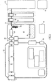
- FIG. 1 shows a generalised schematic view of an apparatus 10 of a portable topical negative pressure (TNP) system.
- TNP topical negative pressure
- FIG. 1 shows a generalised schematic view of an apparatus 10 of a portable topical negative pressure (TNP) system.
- TNP topical negative pressure
- FIG. 1 shows a generalised schematic view of an apparatus 10 of a portable topical negative pressure (TNP) system.
- TNP topical negative pressure
- the apparatus comprises an aspiration conduit 12 operably and an outer surface thereof at one end sealingly attached to a dressing 14.
- the dressing 14 will not be further described here other than to say that it is formed in a known manner from well know materials to those skilled in the dressings art to create a sealed cavity over and around a wound to be treated by TNP therapy with the apparatus of the present invention.
- the aspiration conduit has an in-line connector 16 comprising connector portions 18, 20 intermediate its length between the dressing 14 and a waste canister 22.
- the aspiration conduit between the connector portion 20 and the canister 22 is denoted by a different reference numeral 24 although the fluid path through conduit portions 12 and 24 to the waste canister is continuous.
- the connector portions 18, 20 join conduit portions 12, 24 in a leak-free but disconnectable manner.
- the waste canister 22 is provided with filters 26 which prevent the escape via an exit port 28 of liquid and bacteria from the waste canister.
- the filters may comprise a 1 ⁇ m hydrophobic liquid filter and a 0.2 ⁇ m bacteria filter such that all liquid and bacteria is confined to an interior waste collecting volume of the waste canister 22.
- the exit port 28 of the waste canister 22 mates with an entry/suction port 30 of a device unit 32 by means of mutually sealing connector portions 34, 36 which engage and seal together automatically when the waste canister 22 is attached to the device unit 32, the waste canister 22 and device unit 32 being held together by catch assemblies 38, 40.
- the device unit 32 comprises an aspirant pump 44, an aspirant pressure monitor 46 and an aspirant flowmeter 48 operably connected together.
- the aspiration path takes the aspirated fluid which in the case of fluid on the exit side of exit port 28 is gaseous through a silencer system 50 and a final filter 52 having an activated charcoal matrix which ensures that no odours escape with the gas exhausted from the device 32 via an exhaust port 54.
- the filter 52 material also serves as noise reducing material to enhance the effect of the silencer system 50.
- the device 32 also contains a battery pack 56 to power the apparatus which battery pack also powers the control system 60 which controls a user interface system 62 controlled via a keypad (not shown) and the aspiration pump 44 via signals from sensors 46, 48.
- a power management system 66 is also provided which controls power from the battery pack 56, the recharging thereof and the power requirements of the aspirant pump 44 and other electrically operated components.
- An electrical connector 68 is provided to receive a power input jack 70 from a SELV power supply 72 connected to a mains supply 74 when the user of the apparatus or the apparatus itself is adjacent a convenient mains power socket.
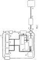
- FIG 2 shows a similar schematic representation to Figure 1 but shows the fluid paths in more detail.
- the wound exudate is aspirated from the wound site/dressing 14 via the conduit 12, the two connector portions 18, 20 and the conduit 24 into the waste canister 22.
- the waste canister 22 comprises a relatively large volume 80 in the region of 500ml into which exudate from the wound is drawn by the aspiration system at an entry port 82.
- the fluid 84 drawn into the canister volume 80 is a mixture of both air drawn into the dressing 14 via the semi-permeable adhesive sealing drape (not shown) and liquid 86 in the form of wound exudates.
- the volume 80 within the canister is also at a lowered pressure and the gaseous element 88 of the aspirated fluids is exhausted from the canister volume 80 via the filters 26 and the waste canister exhaust exit port 28 as bacteria-free gas. From the exit port 28 of the waste canister to the final exhaust port 54 the fluid is gaseous only.
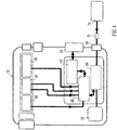
- FIG. 3 shows a schematic diagram showing only the device portion of the apparatus and the power paths in the device of the apparatus embodying the present invention.
- Power is provided mainly by the battery pack 56 when the user is outside their home or workplace, for example, however, power may also be provided by an external mains 74 supplied charging unit 72 which when connected to the device 32 by the socket 68 is capable of both operating the device and recharging the battery pack 56 simultaneously.
- the power management system 66 is included so as to be able to control power of the TNP system.
- the TNP system is a rechargeable, battery powered system but is capable of being run directly from mains electricity as will be described hereinafter more fully with respect to the further figures. If disconnected from the mains the battery has enough stored charge for approximately 8 hours of use in normal conditions.
- batteries having other associated life times between recharge can be utilised. For example batteries providing less than 8 hours or greater than 8 hours can be used.
- the device When connected to the mains the device will run off the mains power and will simultaneously recharge the battery if depleted from portable use. The exact rate of battery recharge will depend on the load on the TNP system. For example, if the wound is very large or there is a significant leak, battery recharge will take longer than if the wound is small and well sealed.
- FIG. 4 shows the device 32 part of the apparatus embodying the present invention and the data paths employed in the control system for control of the aspirant pump and other features of the apparatus.
- a key purpose of the TNP system is to apply negative pressure wound therapy. This is accomplished via the pressure control system which includes the pump and a pump control system.
- the pump applies negative pressure; the pressure control system gives feedback on the pressure at the pump head to the control system; the pump control varies the pump speed based on the difference between the target pressure and the actual pressure at the pump head.
- the pump is controlled by an auxiliary control system.
- the pump is from time to time allowed to "free-wheel” during its duty cycle by turning off the voltage applied to it.
- the spinning motor causes a "back electro-motive force" or BEMF to be generated. This BEMF can be monitored and can be used to provide an accurate measure of pump speed. The speed can thus be adjusted more accurately than can prior art pump systems.
- actual pressure at a wound site is not measured but the difference between a measured pressure (at the pump) and the wound pressure is minimised by the use of large filters and large bore tubes wherever practical. If the pressure control measures that the pressure at the pump head is greater than a target pressure (closer to atmospheric pressure) for a period of time, the device sends an alarm and displays a message alerting the user to a potential problem such as a leak.
- a flow meter may be positioned after the pump and is used to detect when a canister is full or the tube has become blocked. If the flow falls below a certain threshold, the device sounds an alarm and displays a message alerting a user to the potential blockage or full canister.
- the preferred embodiment is of generally oval shape in plan and comprises a device unit 202 and a waste canister 204 connected together by catch arrangements 206.
- the device unit 202 has a liquid crystal display (LCD) 208, which gives text based feedback on the wound therapy being applied, and a membrane keypad 210, the LCD being visible through the membrane of the keypad to enable a user to adjust or set the therapy to be applied to the wound (not shown).
- LCD liquid crystal display
- the device has a lower, generally transverse face 212 in the centre of which is a spigot 214 which forms the suction/entry port 216 to which the aspiration means (to be described below) are connected within the device unit.
- the lower edge of the device unit is provided with a rebated peripheral male mating face 218 which engages with a co-operating peripheral female formation 220 on an upper edge of the waste canister 204 (see Figures 8 and 9 ).
- clips 222 hinged to the canister 204 have an engaging finger (not shown) which co-operates with formations in recesses 226 in the body of the device unit.
- the casing 230 of the device unit is of largely "clamshell" construction comprising front and back mouldings 232, 234, respectively and left-hand and right-hand side inserts 236, 238.
- a central chassis 240 which is fastened to an internal moulded structural member 242 and which chassis acts as a mounting for the electrical circuitry and components and also retains the battery pack 246 and aspiration pump unit 248.
- Various tubing items 250, 252, 254 connect the pump unit 248 and suction/entry port 216 to a final gaseous exhaust via a filter 290.
- Figure 8 shows a partially sectioned side elevation of the apparatus 200, the partial section being around the junction between the device unit 202 and the waste canister 204, a cross section of which is shown at Figure 9 .
- Figure 9 show the rebated edge 218 of the male formation on the device unit co-operating with the female portion 220 defined by an upstanding flange 260 around the top face 262 of the waste canister 204.
- the spigot 214 which has an "O" ring seal 264 therearound sealingly engages with a cylindrical tube portion 266 formed around an exhaust/exit port 268 in the waste canister.
- the spigot 214 of the device is not rigidly fixed to the device casing but is allowed to "float" or move in its location features in the casing to permit the spigot 214 and seal 264 to move to form the best seal with the bore of the cylindrical tube portion 266 on connection of the waste canister to the device unit.
- the waste canister 204 in Figure 9 is shown in an upright orientation much as it would be when worn by a user. Thus, any exudate 270 would be in the bottom of the internal volume of waste receptacle portion 272.
- An aspiration conduit 274 is permanently affixed to an entry port spigot 278 defining an entry port 280 to receive fluid aspirated from a wound (not shown) via the conduit 274.
- Filter members 282 comprising a 0.2 ⁇ m filter and 284 comprising a 1 ⁇ m filter are located by a filter retainer moulding 286 adjacent a top closure member or bulkhead 288 the filter members preventing any liquid or bacteria from being drawn out of the exhaust exit port 268 into the pump and aspiration path through to an exhaust and filter unit 290 which is connected to a casing outlet moulding at 291 via an exhaust tube (not shown) in casing side piece 236.
- the side pieces 236, 238 are provided with recesses 292 having support pins 294 therein to locate a carrying strap (not shown) for use by the patient.
- the side pieces 230 and canister 204 are also provided with features which prevent the canister and device from exhibiting a mutual "wobble" when connected together.
- Ribs (not shown) extending between the canister top closure member 288 and the inner face 300 of the upstanding flange 260 locate in grooves 302 in the device sidewalls when canister and device are connected.
- the casing 230 also houses all of the electrical equipment and control and power management features, the functioning of which was described briefly with respect to Figures 3 and 4 hereinabove.
- the side piece 238 is provided with a socket member 298 to receive a charging jack from an external mains powered battery charger (both not shown).
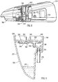
- Figure 10 illustrates how the status of one or more operating parameters associated with the TNP system can be indicated according to an embodiment of the present invention.
- the one or more operating parameters which may be indicated can be selected from a wide range of parameters associated with operation of the device. For example whether or not the device is operating and/or whether or not an onboard battery is running low and/or whether a medicament is being delivered and/or whether a negative pressure is being maintained with a predetermined threshold value and/or whether a pressure being delivered is dangerously outside normal operational characteristics.
- the status can be indicated by delivering a cue such as a visible cue using one or more windows 1000 formed in the casing of the device unit 202.
- One such window 1000 is illustrated in Figure 10 but it will be appreciated that more windows could be provided so that the status of more than one operating parameter may be indicated simultaneously.
- an LED 1001 or other such illumination device such as an incandescent bulb is provided for each parameter which is to be indicated.
- Power and drive signals for the LED are provided on the PCB 1002.
- a light guide 1003 is located at a position between the emission surface of the LED and the underside surface of the window 1000.
- the light guide 1003 includes a light receiving portion 1004 which includes a lower surface 1005 which is contoured to closely match the outer surface of the LED. In this way the lower portion 1004 of the light guide can be brought into intimate proximity with the LED. From the lower surface 1005 the lower portion 1004 of the light guide 1003 flares outwardly in a substantially thrusted conical fashion into a central fixing region 1006 which permits the light guide to be secured rigidly with respect to the casing.
- An upper portion 1007 of the light guide is substantially cylindrical and includes an upper light emitting surface 1008 which emits light through the window 1000 in a fashion to be highly visible to a user.
- Figure 11 illustrates a cut away view of the device unit 202 showing the outer casing secured on the main body of the device unit with the light guide 1003 in position.
- the light guide 1003 acts as a light pipe ducting light from the PCB mounted LED to the prominent position on the device case work. Aptly the window and thus light emitted is visible from all major orientations so that a user is continually able to quickly check on the working parameters of the device.
- Each LED has only three possible states. For example solid green, flashing green and solid red. Solid green indicates that topical negative pressure therapy is as expected. In other words that performance is adequate. Flashing green indicates that there are no urgent warnings and that therapy is still active. Examples of such use are when the battery is low or when the end of product life is expected. The flashing green light thus indicates to a user that whilst operating in an acceptable fashion at present there may be action required if therapy is to be continued. A solid red illumination indicates therapy failure. There may be a number of reasons for this such as leakage in the system or a blockage or a very low battery level. By providing three states for the LED a highly efficient system is provided whereby a user can rapidly verify status of parameters for the TNP system. In addition because of the low complexity the likelihood of interpretation error or reading occurring is minimised. It will be appreciated that this master status LED may be used in conjunction or as an alternative to the on screen text delivered through the LCD display 208 so that greater detailed feedback can be obtained if required.
- Embodiments of the present invention thus provide the user or a carer with a system that gives simple, quick and accurate feedback to describe the TNP system state. Whilst current prior known devices have either no visual feedback on the therapy state for the user or user screen with hard to see text display or incorporate a confusing array of pressure figures and error messages embodiments of the present invention are not encumbered by such problems.
- an audible cue may additionally be provided.
- a buzzer mounted on the circuit board is provided with control signals in the device and a sound tube directs sound to one or more holes (not shown) on the device case.
- the speaker may be mounted close to the surface of the device casing.
- the pitch or length of time a sound is generated may indicate the status of an operating parameter. For example when a problem occurs during TNP operation a buzzer may sound.
- a single 'beep' may issue from time to time to indicate that a battery level is getting low.
- the LCD display 208 may be omitted from the device unit with only one or a few illumination or sound windows 1000 being provided to indicate proper function.
- illumination or sound is not language specific which makes the device unit applicable for multi-regional use or use by users of differing nationality and ability.
Landscapes
- Health & Medical Sciences (AREA)
- Heart & Thoracic Surgery (AREA)
- Hematology (AREA)
- Engineering & Computer Science (AREA)
- Anesthesiology (AREA)
- Biomedical Technology (AREA)
- Vascular Medicine (AREA)
- Life Sciences & Earth Sciences (AREA)
- Animal Behavior & Ethology (AREA)
- General Health & Medical Sciences (AREA)
- Public Health (AREA)
- Veterinary Medicine (AREA)
- Media Introduction/Drainage Providing Device (AREA)
- External Artificial Organs (AREA)
- Measuring Pulse, Heart Rate, Blood Pressure Or Blood Flow (AREA)
Description
- The present invention relates to apparatus and a method for the application of topical negative pressure (TNP) therapy to wounds. In particular, but not exclusively, the present invention relates to a method and apparatus for indicating one or more operating parameters of the TNP system.
- There is much prior art available relating to the provision of apparatus and methods of use thereof for the application of TNP therapy to wounds together with other therapeutic processes intended to enhance the effects of the TNP therapy. Examples of such prior art include those listed and briefly described below.
- TNP therapy assists in the closure and healing of wounds by reducing tissue oedema; encouraging blood flow and granulation of tissue; removing excess exudates and may reduce bacterial load and thus, infection to the wound. Furthermore, TNP therapy permits less outside disturbance of the wound and promotes more rapid healing.
- In our co-pending International patent application,
WO 2004/037334 , apparatus, a wound dressing and a method for aspirating, irrigating and cleansing wounds are described. In very general terms, this invention describes the treatment of a wound by the application of topical negative pressure (TNP) therapy for aspirating the wound together with the further provision of additional fluid for irrigating and/or cleansing the wound, which fluid, comprising both wound exudates and irrigation fluid, is then drawn off by the aspiration means and circulated through means for separating the beneficial materials therein from deleterious materials. The materials which are beneficial to wound healing are recirculated through the wound dressing and those materials deleterious to wound healing are discarded to a waste collection bag or vessel. - In our co-pending International patent application,
WO 2005/04670 WO 2004/037334 with regard to the aspiration, irrigation and cleansing of the wound, however, it further includes the important additional step of providing heating means to control the temperature of that beneficial material being returned to the wound site/dressing so that it is at an optimum temperature, for example, to have the most efficacious therapeutic effect on the wound. In our co-pending International patent application,WO 2005/105180 , apparatus and a method for the aspiration, irrigation and/or cleansing of wounds are described. Again, in very general terms, this document describes similar apparatus to the two previously mentioned documents hereinabove but with the additional step of providing means for the supply and application of physiologically active agents to the wound site/dressing to promote wound healing. - A topical negative pressure system with status indication is described in
WO2007/030598 . However, the above apparatus and methods are generally only applicable to a patient when hospitalised as the apparatus is complex, needing people having specialist knowledge in how to operate and maintain the apparatus, and also relatively heavy and bulky, not being adapted for easy mobility outside of a hospital environment by a patient, for example. - Some patients having relatively less severe wounds which do not require continuous hospitalisation, for example, but whom nevertheless would benefit from the prolonged application of TNP therapy, could be treated at home or at work subject to the availability of an easily portable and maintainable TNP therapy apparatus.
-
GB-A-2 307 180 - In many known portable units certain parameters associated with operation of the portable unit such as time remaining due to battery life, number of doses left, whether operation is running smoothly or whether there is a potential fault are not indicated to a user at all. This means that a user may be unaware of any potential problems and may be unable to take predictive action. Furthermore some portable units which provide some type of user display do so in a manner which is complicated and thus prone to reading error on the part of a user. Such displays may also utilise large quantities of power which can reduce available run/operation time.
- A still further problem with known portable units is that displays used to display conditions of certain parameters may not be easy to see and/or read from a distance. This is particularly so for LCD displays and when there are low light conditions such as night time operation
- It is an aim of the present invention to at least partly mitigate the above-mentioned problems.
- It is an aim of embodiments of the present invention to provide a method and apparatus for indicating the status of one or more parameters associated with the TNP system. It is an aim of further embodiments of the present invention to provide a manner of providing a user with status information in a manner which is readily available, easy to understand and thus not prone to error and yet which does not unduly drain a portable unit of power.
- The invention is as claimed in the claims.
- According to a first aspect of the disclosure there is provided a method of indicating status of at least one operating parameter associated with a topical negative pressure (TNP) system, comprising the steps of:
- generating a cue having at least one characteristic corresponding to a status of at least one operating parameter associated with the TNP system.
- The invention is comprised in part of an overall apparatus for the provision of TNP therapy to a patient in almost any environment. The apparatus is lightweight, may be mains or battery powered by a rechargeable battery pack contained within a device (henceforth, the term "device" is used to connote a unit which may contain all of the control, power supply, power supply recharging, electronic indicator means and means for initiating and sustaining aspiration functions to a wound and any further necessary functions of a similar nature). When outside the home, for example, the apparatus may provide for an extended period of operation on battery power and in the home, for example, the device may be connected to the mains by a charger unit whilst still being used and operated by the patient.
- The overall apparatus comprises: a dressing covering the wound and sealing at least an open end of an aspiration conduit to a cavity formed over the wound by the dressing; an aspiration tube comprising at least one lumen therethrough leading from the wound dressing to a waste material canister for collecting and holding wound exudates/waste material prior to disposal; and, a power, control and aspiration initiating and sustaining device associated with the waste canister.
- The dressing covering the wound may be any type of dressing normally employed with TNP therapy and, in very general terms, may comprise, for example, a semi-permeable, flexible, self-adhesive drape material, as is known in the dressings art, to cover the wound and seal with surrounding sound tissue to create a sealed cavity or void over the wound. There may aptly be a porous barrier and support member in the cavity between the wound bed and the covering material to enable an even vacuum distribution to be achieved over the area of the wound. The porous barrier and support member being, for example, a gauze, a foam an inflatable bag or known wound contact type material resistant to crushing under the levels of vacuum created and which permits transfer of wound exudates across the wound area to the aspiration conduit sealed to the flexible cover drape over the wound.
- The aspiration conduit may be a plain flexible tube, for example, having a single lumen therethrough and made from a plastics material compatible with raw tissue, for example. However, the aspiration conduit may have a plurality of lumens therethrough to achieve specific objectives relating to the invention. A portion of the tube sited within the sealed cavity over the wound may have a structure to enable continued aspiration and evacuation of wound exudates without becoming constricted or blocked even at the higher levels of the negative pressure range envisaged.
- It is envisaged that the negative pressure range for the apparatus embodying the present invention may be between about -50 mmHg and -200 mmHg (note that these pressures are relative to normal ambient atmospheric pressure thus, -200 mmHg would be about 560 mmHg in practical terms). Aptly, the pressure range may be between about -75 mmHg and -150 mmHg. Alternatively a pressure range of upto -75 mmHg, upto -80 mmHg or over -80 mmHg can be used. Also aptly a pressure range of below - 75 mmHg could be used. Alternatively a pressure range of over -100 mmHg could be used or over -150 mmHg.
- The aspiration conduit at its distal end remote from the dressing may be attached to the waste canister at an inlet port or connector. The device containing the means for initiating and sustaining aspiration of the wound/dressing may be situated between the dressing and waste canister, however, in a preferred embodiment of the apparatus embodying the present invention, the device may aspirate the wound/dressing via the canister thus, the waste canister may preferably be sited between the wound/dressing and device.
- The aspiration conduit at the waste material canister end may preferably be bonded to the waste canister to prevent inadvertent detachment when being caught on an obstruction, for example.
- The canister may be a plastics material moulding or a composite unit comprising a plurality of separate mouldings. The canister may aptly be translucent or transparent in order to visually determine the extent of filling with exudates. However, the canister and device may in some embodiments provide automatic warning of imminent canister full condition and may also provide means for cessation of aspiration when the canister reaches the full condition.
- The canister may be provided with filters to prevent the exhaust of liquids and odours therefrom and also to prevent the expulsion of bacteria into the atmosphere. Such filters may comprise a plurality of filters in series. Examples of suitable filters may comprise hydrophobic filters of 0.2µm pore size, for example, in respect of sealing the canister against bacteria expulsion and 1 µm against liquid expulsion.
- Aptly, the filters may be sited at an upper portion of the waste canister in normal use, that is when the apparatus is being used or carried by a patient the filters are in an upper position and separated from the exudate liquid in the waste canister by gravity. Furthermore, such an orientation keeps the waste canister outlet or exhaust exit port remote from the exudate surface.
- Aptly the waste canister may be filled with an absorbent gel such as ISOLYSEL (trade mark), for example, as an added safeguard against leakage of the canister when full and being changed and disposed of. Added advantages of a gel matrix within the exudate storing volume of the waste canister are that it prevents excessive movement, such as slopping, of the liquid, minimises bacterial growth and minimises odours.
- The waste canister may also be provided with suitable means to prevent leakage thereof both when detached from the device unit and also when the aspiration conduit is detached from the wound site/dressing.
- The canister may have suitable means to prevent emptying by a user (without tools or damage to the canister) such that a full or otherwise end-of-life canister may only be disposed of with waste fluid still contained.
- The device and waste canister may have mutually complementary means for connecting a device unit to a waste canister whereby the aspiration means in the device unit automatically connects to an evacuation port on the waste canister such that there is a continuous aspiration path from the wound site/dressing to an exhaust port on the device.
- Aptly, the exhaust port from the fluid path through the apparatus is provided with filter means to prevent offensive odours from being ejected into the atmosphere.
- In general terms the device unit comprises an aspirant pump; means for monitoring pressure applied by the aspirant pump; a flowmeter to monitor fluid flow through the aspirant pump; a control system which controls the aspirant pump in response to signals from sensors such as the pressure monitoring means and the flowmeter, for example, and which control system also controls a power management system with regard to an on-board battery pack and the charging thereof and lastly a user interface system whereby various functions of the device such as pressure level set point, for example, may be adjusted (including stopping and starting of the apparatus) by a user. The device unit may contain all of the above features within a single unified casing.
- In view of the fact that the device unit contains the majority of the intrinsic equipment cost therein ideally it will also be able to survive impact, tolerate cleaning in order to be reusable by other patients.
- In terms of pressure capability the aspiration means may be able to apply a maximum pressure drop of at least -200 mmHg to a wound site/dressing. The apparatus is capable of maintaining a predetermined negative pressure even under conditions where there is a small leak of air into the system and a high exudate flow.
- The pressure control system may prevent the minimum pressure achieved from exceeding for example -200 mmHg so as not to cause undue patient discomfort. The pressure required may be set by the user at a number of discreet levels such as -50, - 75, -100, -125, -150, -175 mmHg, for example, depending upon the needs of the wound in question and the advice of a clinician. Thus suitable pressure ranges in use may be from -25 to -80 mmHg, or -50 to -76 mmHg, or -50 to -75 mmHg as examples. The control system may also advantageously be able to maintain the set pressure within a tolerance band of +/- 10 mmHg of the set point for 95% of the time the apparatus is operating given that leakage and exudation rates are within expected or normal levels. Aptly, the control system may trigger alarm means such as a flashing light, buzzer or any other suitable means when various abnormal conditions apply such as, for example: pressure outside set value by a large amount due to a gross leak of air into system; duty on the aspiration pump too high due to a relatively smaller leakage of air into the system; pressure differential between wound site and pump is too high due, for example, to a blockage or waste canister full.
- The apparatus of the present invention may be provided with a carry case and suitable support means such as a shoulder strap or harness, for example. The carry case may be adapted to conform to the shape of the apparatus comprised in the joined together device and waste canister. In particular, the carry case may be provided with a bottom opening flap to permit the waste canister to be changed without complete removal of the apparatus form the carry case.
- The carry case may be provided with an aperture covered by a displaceable flap to enable user access to a keypad for varying the therapy applied by the apparatus.
- According to a second aspect of the disclosure, there is provided apparatus that indicates status of at least one operating parameter associated with a topical negative pressure (TNP) system, comprising:
- at least one LED that generates illumination, visible to a user of a TNP system, having at least three characteristics corresponding to a status of at least one operating parameter associated with the TNP system, the at least three characteristics comprising:
- a first characteristic comprising a first solid colour for indicating a first status;
- a second characteristic comprising a second solid colour for indicating a second status, the second solid colour different from the first solid colour; and
- a third characteristic comprising a flashing of the first colour for indicating a third status,
- According to a third aspect of the disclosure there is provided apparatus that indicates status of at least one operating parameter associated with a topical negative pressure (TNP) system; comprising:
- at least one buzzer unit that generates noise audible to a user having at least three characteristics corresponding to a status of at least one operating parameter associated with the TNP system, the at least three characteristics comprising:
- a first characteristic comprising no sound for indicating a first status;
- a second characteristic comprising a buzzer for indicating a second status; and
- Embodiments of the present disclosure provide a method and apparatus in which at least one operating parameter associated with a TNP system can be indicated to a user. A visible and/or audible cue such as a steady or flashing light or noise generated by a buzzer can be used so that the status can be used over a distance and possibly under poor light conditions. The audible or visible cue can be constant or repeated so as to provide further status information.
- In order that the present invention may be more fully understood, examples will now be described by way of illustration only with reference to the accompanying drawings, of which:
-
Figure 1 shows a generalised schematic block diagram showing a general view of an apparatus and the constituent apparatus features thereof; -
Figure 2 shows a similar generalised schematic block diagram toFigure 1 and showing fluid paths therein; -
Figure 3 shows a generalised schematic block diagram similar toFigure 1 but of a device unit only and showing power paths for the various power consuming/producing features of the apparatus; -
Figure 4 shows a similar generalised schematic block diagram toFigure 3 of the device unit and showing control system data paths for controlling the various functions and components of the apparatus; -
Figure 5 shows a perspective view of an apparatus; -
Figure 6 shows a perspective view of an assembled device unit of the apparatus ofFigure 5 ; -
Figure 7 shows an exploded view of the device unit ofFigure 6 ; -
Figure 8 shows a partially sectioned side elevation view through the interface between a waste canister and device unit of the apparatus; -
Figure 9 shows a cross section through a waste canister of the apparatus ofFigures 5 to 8 ; -
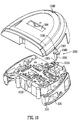
Figure 10 shows an exploded view of a PCB and top case; and -
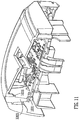
Figure 11 shows a cross-section through a PCB and top case assembly. - Referring now to
Figures 1 to 4 of the drawings and where the same or similar features are denoted by common reference numerals. -
Figure 1 shows a generalised schematic view of anapparatus 10 of a portable topical negative pressure (TNP) system. It will be understood that embodiments of the present invention are generally applicable to use in such a TNP system. Briefly, negative pressure wound therapy assists in the closure and healing of many forms of "hard to heal" wounds by reducing tissue oedema; encouraging blood flow and granular tissue formation; removing excess exudate and may reduce bacterial load (and, therefore, infection). In addition the therapy allows for less disturbance of a wound leading to more rapid healing. The TNP system is detailed further hereinafter but in summary includes a portable body including a canister and a device with the device capable of providing an extended period of continuous therapy within at least a one year life span. The system is connected to a patient via a length of tubing with an end of the tubing operably secured to a wound dressing on the patient. - More particularly, as shown in
Figure 1 , the apparatus comprises anaspiration conduit 12 operably and an outer surface thereof at one end sealingly attached to adressing 14. The dressing 14 will not be further described here other than to say that it is formed in a known manner from well know materials to those skilled in the dressings art to create a sealed cavity over and around a wound to be treated by TNP therapy with the apparatus of the present invention. The aspiration conduit has an in-line connector 16 comprisingconnector portions waste canister 22. The aspiration conduit between theconnector portion 20 and thecanister 22 is denoted by adifferent reference numeral 24 although the fluid path throughconduit portions connector portions join conduit portions waste canister 22 is provided withfilters 26 which prevent the escape via anexit port 28 of liquid and bacteria from the waste canister. The filters may comprise a 1µm hydrophobic liquid filter and a 0.2µm bacteria filter such that all liquid and bacteria is confined to an interior waste collecting volume of thewaste canister 22. Theexit port 28 of thewaste canister 22 mates with an entry/suction port 30 of adevice unit 32 by means of mutually sealingconnector portions waste canister 22 is attached to thedevice unit 32, thewaste canister 22 anddevice unit 32 being held together bycatch assemblies device unit 32 comprises anaspirant pump 44, an aspirant pressure monitor 46 and anaspirant flowmeter 48 operably connected together. The aspiration path takes the aspirated fluid which in the case of fluid on the exit side ofexit port 28 is gaseous through asilencer system 50 and afinal filter 52 having an activated charcoal matrix which ensures that no odours escape with the gas exhausted from thedevice 32 via anexhaust port 54. Thefilter 52 material also serves as noise reducing material to enhance the effect of thesilencer system 50. Thedevice 32 also contains abattery pack 56 to power the apparatus which battery pack also powers thecontrol system 60 which controls auser interface system 62 controlled via a keypad (not shown) and theaspiration pump 44 via signals fromsensors power management system 66 is also provided which controls power from thebattery pack 56, the recharging thereof and the power requirements of theaspirant pump 44 and other electrically operated components. Anelectrical connector 68 is provided to receive apower input jack 70 from aSELV power supply 72 connected to amains supply 74 when the user of the apparatus or the apparatus itself is adjacent a convenient mains power socket. -
Figure 2 shows a similar schematic representation toFigure 1 but shows the fluid paths in more detail. The wound exudate is aspirated from the wound site/dressing 14 via theconduit 12, the twoconnector portions conduit 24 into thewaste canister 22. Thewaste canister 22 comprises a relativelylarge volume 80 in the region of 500ml into which exudate from the wound is drawn by the aspiration system at anentry port 82. The fluid 84 drawn into thecanister volume 80 is a mixture of both air drawn into the dressing 14 via the semi-permeable adhesive sealing drape (not shown) and liquid 86 in the form of wound exudates. Thevolume 80 within the canister is also at a lowered pressure and thegaseous element 88 of the aspirated fluids is exhausted from thecanister volume 80 via thefilters 26 and the waste canisterexhaust exit port 28 as bacteria-free gas. From theexit port 28 of the waste canister to thefinal exhaust port 54 the fluid is gaseous only. -
Figure 3 shows a schematic diagram showing only the device portion of the apparatus and the power paths in the device of the apparatus embodying the present invention. Power is provided mainly by thebattery pack 56 when the user is outside their home or workplace, for example, however, power may also be provided by anexternal mains 74 supplied chargingunit 72 which when connected to thedevice 32 by thesocket 68 is capable of both operating the device and recharging thebattery pack 56 simultaneously. Thepower management system 66 is included so as to be able to control power of the TNP system. The TNP system is a rechargeable, battery powered system but is capable of being run directly from mains electricity as will be described hereinafter more fully with respect to the further figures. If disconnected from the mains the battery has enough stored charge for approximately 8 hours of use in normal conditions. It will be appreciated that batteries having other associated life times between recharge can be utilised. For example batteries providing less than 8 hours or greater than 8 hours can be used. When connected to the mains the device will run off the mains power and will simultaneously recharge the battery if depleted from portable use. The exact rate of battery recharge will depend on the load on the TNP system. For example, if the wound is very large or there is a significant leak, battery recharge will take longer than if the wound is small and well sealed. -
Figure 4 shows thedevice 32 part of the apparatus embodying the present invention and the data paths employed in the control system for control of the aspirant pump and other features of the apparatus. A key purpose of the TNP system is to apply negative pressure wound therapy. This is accomplished via the pressure control system which includes the pump and a pump control system. The pump applies negative pressure; the pressure control system gives feedback on the pressure at the pump head to the control system; the pump control varies the pump speed based on the difference between the target pressure and the actual pressure at the pump head. In order to improve accuracy of pump speed and hence provide smoother and more accurate application of the negative pressure at a wound site, the pump is controlled by an auxiliary control system. The pump is from time to time allowed to "free-wheel" during its duty cycle by turning off the voltage applied to it. The spinning motor causes a "back electro-motive force" or BEMF to be generated. This BEMF can be monitored and can be used to provide an accurate measure of pump speed. The speed can thus be adjusted more accurately than can prior art pump systems. - According to embodiments of the present invention, actual pressure at a wound site is not measured but the difference between a measured pressure (at the pump) and the wound pressure is minimised by the use of large filters and large bore tubes wherever practical. If the pressure control measures that the pressure at the pump head is greater than a target pressure (closer to atmospheric pressure) for a period of time, the device sends an alarm and displays a message alerting the user to a potential problem such as a leak.
- In addition to pressure control a separate flow control system can be provided. A flow meter may be positioned after the pump and is used to detect when a canister is full or the tube has become blocked. If the flow falls below a certain threshold, the device sounds an alarm and displays a message alerting a user to the potential blockage or full canister.
- Referring now to
Figures 5 to 9 which show various views and cross sections of a preferred embodiment ofapparatus 200 embodying the present invention. The preferred embodiment is of generally oval shape in plan and comprises adevice unit 202 and awaste canister 204 connected together bycatch arrangements 206. Thedevice unit 202 has a liquid crystal display (LCD) 208, which gives text based feedback on the wound therapy being applied, and amembrane keypad 210, the LCD being visible through the membrane of the keypad to enable a user to adjust or set the therapy to be applied to the wound (not shown). The device has a lower, generallytransverse face 212 in the centre of which is aspigot 214 which forms the suction/entry port 216 to which the aspiration means (to be described below) are connected within the device unit. The lower edge of the device unit is provided with a rebated peripheralmale mating face 218 which engages with a co-operating peripheralfemale formation 220 on an upper edge of the waste canister 204 (seeFigures 8 and 9 ). On each side of thedevice 202,clips 222 hinged to thecanister 204 have an engaging finger (not shown) which co-operates with formations inrecesses 226 in the body of the device unit. FromFigure 7 it may be seen that thecasing 230 of the device unit is of largely "clamshell" construction comprising front andback mouldings casing 230 is acentral chassis 240 which is fastened to an internal mouldedstructural member 242 and which chassis acts as a mounting for the electrical circuitry and components and also retains thebattery pack 246 andaspiration pump unit 248.Various tubing items pump unit 248 and suction/entry port 216 to a final gaseous exhaust via afilter 290.Figure 8 shows a partially sectioned side elevation of theapparatus 200, the partial section being around the junction between thedevice unit 202 and thewaste canister 204, a cross section of which is shown atFigure 9 . Theses views show therebated edge 218 of the male formation on the device unit co-operating with thefemale portion 220 defined by anupstanding flange 260 around thetop face 262 of thewaste canister 204. When the waste canister is joined to the device unit, thespigot 214 which has an "O"ring seal 264 therearound sealingly engages with acylindrical tube portion 266 formed around an exhaust/exit port 268 in the waste canister. Thespigot 214 of the device is not rigidly fixed to the device casing but is allowed to "float" or move in its location features in the casing to permit thespigot 214 and seal 264 to move to form the best seal with the bore of thecylindrical tube portion 266 on connection of the waste canister to the device unit. Thewaste canister 204 inFigure 9 is shown in an upright orientation much as it would be when worn by a user. Thus, anyexudate 270 would be in the bottom of the internal volume ofwaste receptacle portion 272. Anaspiration conduit 274 is permanently affixed to anentry port spigot 278 defining anentry port 280 to receive fluid aspirated from a wound (not shown) via theconduit 274.Filter members 282 comprising a 0.2µm filter and 284 comprising a 1µm filter are located by afilter retainer moulding 286 adjacent a top closure member orbulkhead 288 the filter members preventing any liquid or bacteria from being drawn out of theexhaust exit port 268 into the pump and aspiration path through to an exhaust andfilter unit 290 which is connected to a casing outlet moulding at 291 via an exhaust tube (not shown) incasing side piece 236. Theside pieces recesses 292 having support pins 294 therein to locate a carrying strap (not shown) for use by the patient. Theside pieces 230 andcanister 204 are also provided with features which prevent the canister and device from exhibiting a mutual "wobble" when connected together. Ribs (not shown) extending between the canistertop closure member 288 and theinner face 300 of theupstanding flange 260 locate ingrooves 302 in the device sidewalls when canister and device are connected. Thecasing 230 also houses all of the electrical equipment and control and power management features, the functioning of which was described briefly with respect toFigures 3 and4 hereinabove. Theside piece 238 is provided with asocket member 298 to receive a charging jack from an external mains powered battery charger (both not shown). -
Figure 10 illustrates how the status of one or more operating parameters associated with the TNP system can be indicated according to an embodiment of the present invention. It will be appreciated that the one or more operating parameters which may be indicated can be selected from a wide range of parameters associated with operation of the device. For example whether or not the device is operating and/or whether or not an onboard battery is running low and/or whether a medicament is being delivered and/or whether a negative pressure is being maintained with a predetermined threshold value and/or whether a pressure being delivered is dangerously outside normal operational characteristics. The status can be indicated by delivering a cue such as a visible cue using one ormore windows 1000 formed in the casing of thedevice unit 202. Onesuch window 1000 is illustrated inFigure 10 but it will be appreciated that more windows could be provided so that the status of more than one operating parameter may be indicated simultaneously. - As illustrated in
Figure 10 which shows an exploded view of thedevice unit 202, anLED 1001 or other such illumination device such as an incandescent bulb is provided for each parameter which is to be indicated. Power and drive signals for the LED are provided on thePCB 1002. - A
light guide 1003 is located at a position between the emission surface of the LED and the underside surface of thewindow 1000. Thelight guide 1003 includes alight receiving portion 1004 which includes alower surface 1005 which is contoured to closely match the outer surface of the LED. In this way thelower portion 1004 of the light guide can be brought into intimate proximity with the LED. From thelower surface 1005 thelower portion 1004 of thelight guide 1003 flares outwardly in a substantially thrusted conical fashion into acentral fixing region 1006 which permits the light guide to be secured rigidly with respect to the casing. Anupper portion 1007 of the light guide is substantially cylindrical and includes an upperlight emitting surface 1008 which emits light through thewindow 1000 in a fashion to be highly visible to a user. -
Figure 11 illustrates a cut away view of thedevice unit 202 showing the outer casing secured on the main body of the device unit with thelight guide 1003 in position. Thelight guide 1003 acts as a light pipe ducting light from the PCB mounted LED to the prominent position on the device case work. Aptly the window and thus light emitted is visible from all major orientations so that a user is continually able to quickly check on the working parameters of the device. - Each LED has only three possible states. For example solid green, flashing green and solid red. Solid green indicates that topical negative pressure therapy is as expected. In other words that performance is adequate. Flashing green indicates that there are no urgent warnings and that therapy is still active. Examples of such use are when the battery is low or when the end of product life is expected. The flashing green light thus indicates to a user that whilst operating in an acceptable fashion at present there may be action required if therapy is to be continued. A solid red illumination indicates therapy failure. There may be a number of reasons for this such as leakage in the system or a blockage or a very low battery level. By providing three states for the LED a highly efficient system is provided whereby a user can rapidly verify status of parameters for the TNP system. In addition because of the low complexity the likelihood of interpretation error or reading occurring is minimised. It will be appreciated that this master status LED may be used in conjunction or as an alternative to the on screen text delivered through the
LCD display 208 so that greater detailed feedback can be obtained if required. - Embodiments of the present invention thus provide the user or a carer with a system that gives simple, quick and accurate feedback to describe the TNP system state. Whilst current prior known devices have either no visual feedback on the therapy state for the user or user screen with hard to see text display or incorporate a confusing array of pressure figures and error messages embodiments of the present invention are not encumbered by such problems.
- The use of an LED in a prominent position on the device that shows the state of the therapy being delivered with an easy to understand colour coding delivers a highly effective system. The user or carer can thus verify the status of the system very quickly without confusion of error codes or pressure figures.
- Rather than delivering a visual cue such as illumination generated by an LED or other such light source an audible cue may additionally be provided. A buzzer mounted on the circuit board is provided with control signals in the device and a sound tube directs sound to one or more holes (not shown) on the device case. Rather than a sound tube the speaker may be mounted close to the surface of the device casing. The pitch or length of time a sound is generated may indicate the status of an operating parameter. For example when a problem occurs during TNP operation a buzzer may sound. A single 'beep' may issue from time to time to indicate that a battery level is getting low.
- It will be appreciated that according to embodiments of the present invention the
LCD display 208 may be omitted from the device unit with only one or a few illumination orsound windows 1000 being provided to indicate proper function. With such a system because it is not icon based and would give audible and/or visual feedback based purely on the tone, repetitiveness and/or colour of the LED a simple to use system is provided. In addition illumination or sound is not language specific which makes the device unit applicable for multi-regional use or use by users of differing nationality and ability. - Throughout the description and claims of this specification, the words "comprise" and "contain" and variations of the words, for example "comprising" and "comprises", means "including but not limited to", and is not intended to (and does not) exclude other moieties, additives, components, integers or steps.
- Throughout the description and claims of this specification, the singular encompasses the plural unless the context otherwise requires. In particular, where the indefinite article is used, the specification is to be understood as contemplating plurality as well as singularity, unless the context requires otherwise.
- Features, integers, characteristics, compounds, chemical moieties or groups described in conjunction with a particular aspect, embodiment or example of the invention are to be understood to be applicable to any other aspect, embodiment or example described herein unless incompatible therewith.
Claims (15)
- A method of indicating status of at least one operating parameter associated with a topical negative pressure (TNP) system, characterized by the steps of:generating, as an illumination from an LED (1001) having only three possible states, a cue having three characteristics corresponding to a status of at least one operating parameter associated with the TNP system, the three characteristics comprising:a first characteristic comprising a first solid colour for indicating normal operation;a second characteristic comprising a second solid colour for indicating failed operation, the second solid color different from the first solid color; anda third characteristic comprising a flashing of the first colour for indicating a non-urgent warning.
- The method as claimed in claim 1, further comprising the steps of:generating the illumination from the LED (1001) located in a cavity region of a case of the TNP system; andvia a light-pipe element, directing the illumination to a viewing window (1000) element visible to the user on an outer surface of the case.
- The method as claimed in claim 2, wherein the viewing window (1000) element comprises a domed surface and/or a prismed surface or scattering surface.
- The method as claimed in claim 1, further comprising the steps of:generating the illumination from the LED (1001) mounted at a visible surface of a case of the TNP system.
- The method as claimed in any preceding claim, further comprising the steps of:providing illumination having only two possible colours from the LED (1001).
- The method as claimed in any preceding claim, further comprising the steps of:providing illumination having only a solid or flashing state from LED (1001).
- The method as claimed in any preceding claim, further comprising the steps of:via an illuminated user display located on an outer surface of a case of the TNP system, providing light or graphic symbols indicating further status information associated with operation of the TNP system.
- The method as claimed in any preceding claim, further comprising the steps of:generating the cue as an audible noise from a buzzer unit.
- Apparatus that indicates status of at least one operating parameter associated with a topical negative pressure (TNP) system, characterized in that
the apparatus comprises an LED (1001) having only three possible states that generates an illumination, visible to a user of a TNP system, having three characteristics corresponding to a status of at least one operating parameter associated with the TNP system, the three characteristics comprising:a first characteristic comprising a first solid colour for indicating normal operation;a second characteristic comprising a second solid colour for indicating failed operation, the second solid color different from the first solid color; anda third characteristic comprising a flashing of the first colour for indicating a non-urgent warning. - The apparatus as claimed in claim 9, further comprising:the LED (1001) is mounted at a visible surface of a case of the TNP system.
- The apparatus as claimed in claim 9, wherein the LED (1001) is mounted in a cavity region in a case of the TNP system; and wherein the apparatus further comprises:a viewing window element disposed at a visible surface of the case of the TNP system; anda light-pipe element arranged to direct illumination from the LED (1001) to the viewing window element (1000).
- The apparatus as claimed in claim 11 wherein the viewing window (1000) element
comprises a domed surface and/or a prismed surface or scattering surface. - The apparatus as claimed in claim 11 or 12 wherein:the light-pipe element comprises a body formed from an at least partially transparent material, said body comprising a generally conical portion with a narrow end locatable proximate to the LED (1001) and a remainder end extending into a substantially cylindrical portion.
- The apparatus as claimed in claim 13, wherein:the narrow end of the body of the light-pipe element has at least one recessed end region to closely fit over the LED (1001).
- The apparatus as claimed in claim 13 or claim 14, wherein:a circular outer surface of the cylindrical portion of the light-pipe element body provides the viewing window (1000).
Applications Claiming Priority (2)
| Application Number | Priority Date | Filing Date | Title |
|---|---|---|---|
| GBGB0712760.8A GB0712760D0 (en) | 2007-07-02 | 2007-07-02 | Status indication |
| PCT/GB2008/002113 WO2009004289A2 (en) | 2007-07-02 | 2008-06-20 | Topical negative pressure system with status indication |
Publications (2)
| Publication Number | Publication Date |
|---|---|
| EP2162162A2 EP2162162A2 (en) | 2010-03-17 |
| EP2162162B1 true EP2162162B1 (en) | 2018-01-24 |
Family
ID=38421039
Family Applications (1)
| Application Number | Title | Priority Date | Filing Date |
|---|---|---|---|
| EP08775764.7A Active EP2162162B1 (en) | 2007-07-02 | 2008-06-20 | Topical negative pressure system with status indication |
Country Status (11)
| Country | Link |
|---|---|
| US (1) | US8294586B2 (en) |
| EP (1) | EP2162162B1 (en) |
| AU (1) | AU2008270078B2 (en) |
| CA (1) | CA2691162C (en) |
| DK (1) | DK2162162T3 (en) |
| ES (1) | ES2663270T3 (en) |
| GB (1) | GB0712760D0 (en) |
| HU (1) | HUE038901T2 (en) |
| NO (1) | NO2162162T3 (en) |
| WO (1) | WO2009004289A2 (en) |
| ZA (1) | ZA200908545B (en) |
Families Citing this family (77)
| Publication number | Priority date | Publication date | Assignee | Title |
|---|---|---|---|---|
| GB0224986D0 (en) | 2002-10-28 | 2002-12-04 | Smith & Nephew | Apparatus |
| GB0325129D0 (en) | 2003-10-28 | 2003-12-03 | Smith & Nephew | Apparatus in situ |
| US10058642B2 (en) | 2004-04-05 | 2018-08-28 | Bluesky Medical Group Incorporated | Reduced pressure treatment system |
| US7753894B2 (en) | 2004-04-27 | 2010-07-13 | Smith & Nephew Plc | Wound cleansing apparatus with stress |
| JP2009506878A (en) | 2005-09-07 | 2009-02-19 | タイコ ヘルスケア グループ リミテッド パートナーシップ | Self-contained wound care with micropump |
| US7779625B2 (en) | 2006-05-11 | 2010-08-24 | Kalypto Medical, Inc. | Device and method for wound therapy |
| CA2604623C (en) | 2006-09-28 | 2018-10-30 | Tyco Healthcare Group Lp | Portable wound therapy system |
| EP2081618B1 (en) | 2006-10-13 | 2016-01-06 | Bluesky Medical Group Inc. | Improved control circuit and apparatus for negative pressure wound treatment |
| USD602584S1 (en) * | 2007-07-02 | 2009-10-20 | Smith & Nephew Plc | Canister |
| USD602582S1 (en) * | 2007-07-02 | 2009-10-20 | Smith & Nephew LLC | Therapy unit assembly |
| US9408954B2 (en) | 2007-07-02 | 2016-08-09 | Smith & Nephew Plc | Systems and methods for controlling operation of negative pressure wound therapy apparatus |
| GB0712737D0 (en) * | 2007-07-02 | 2007-08-08 | Smith & Nephew | Apparatus |
| GB0712763D0 (en) | 2007-07-02 | 2007-08-08 | Smith & Nephew | Apparatus |
| GB0715211D0 (en) * | 2007-08-06 | 2007-09-12 | Smith & Nephew | Apparatus |
| GB0715259D0 (en) | 2007-08-06 | 2007-09-12 | Smith & Nephew | Canister status determination |
| GB0715212D0 (en) * | 2007-08-06 | 2007-09-12 | Smith & Nephew | Apparatus |
| US12121648B2 (en) | 2007-08-06 | 2024-10-22 | Smith & Nephew Plc | Canister status determination |
| GB0722820D0 (en) | 2007-11-21 | 2008-01-02 | Smith & Nephew | Vacuum assisted wound dressing |
| JP5613566B2 (en) | 2007-11-21 | 2014-10-22 | スミス アンド ネフュー ピーエルシーSmith & Nephew Public Limited Company | Wound dressing |
| CN104382691B (en) | 2007-11-21 | 2018-08-31 | 史密夫及内修公开有限公司 | wound dressing |
| GB0723855D0 (en) | 2007-12-06 | 2008-01-16 | Smith & Nephew | Apparatus and method for wound volume measurement |
| GB0803564D0 (en) | 2008-02-27 | 2008-04-02 | Smith & Nephew | Fluid collection |
| US10912869B2 (en) | 2008-05-21 | 2021-02-09 | Smith & Nephew, Inc. | Wound therapy system with related methods therefor |
| US8177763B2 (en) | 2008-09-05 | 2012-05-15 | Tyco Healthcare Group Lp | Canister membrane for wound therapy system |
| US8414519B2 (en) | 2008-05-21 | 2013-04-09 | Covidien Lp | Wound therapy system with portable container apparatus |
| US8827983B2 (en) | 2008-08-21 | 2014-09-09 | Smith & Nephew, Inc. | Sensor with electrical contact protection for use in fluid collection canister and negative pressure wound therapy systems including same |
| US8882678B2 (en) | 2009-03-13 | 2014-11-11 | Atrium Medical Corporation | Pleural drainage system and method of use |
| EP2419157A4 (en) | 2009-04-17 | 2018-01-03 | Kalypto Medical, Inc. | Negative pressure wound therapy device |
| US20110196321A1 (en) | 2009-06-10 | 2011-08-11 | Tyco Healthcare Group Lp | Fluid Collection Canister Including Canister Top with Filter Membrane and Negative Pressure Wound Therapy Systems Including Same |
| DE102009038130A1 (en) | 2009-08-12 | 2011-02-17 | ATMOS Medizin Technik GmbH & Co. KG | A user portable device for providing negative pressure for medical applications |
| US9061095B2 (en) | 2010-04-27 | 2015-06-23 | Smith & Nephew Plc | Wound dressing and method of use |
| GB201015656D0 (en) | 2010-09-20 | 2010-10-27 | Smith & Nephew | Pressure control apparatus |
| JP2014500538A (en) | 2010-10-12 | 2014-01-09 | タニス,ケヴィン ジェイ. | Medical equipment |
| JP2014516709A (en) | 2011-05-24 | 2014-07-17 | カリプト・メディカル・インコーポレイテッド | Device with controller and pump module for providing negative pressure for wound treatment |
| US9058634B2 (en) | 2011-05-24 | 2015-06-16 | Kalypto Medical, Inc. | Method for providing a negative pressure wound therapy pump device |
| US9067003B2 (en) | 2011-05-26 | 2015-06-30 | Kalypto Medical, Inc. | Method for providing negative pressure to a negative pressure wound therapy bandage |
| DE102011076868A1 (en) | 2011-06-01 | 2012-12-06 | Paul Hartmann Ag | Device for providing negative pressure for the negative pressure treatment of wounds with a holding or carrying device |
| US9610388B2 (en) * | 2011-10-31 | 2017-04-04 | Smith & Nephew, Inc. | Apparatuses and methods for detecting leaks in a negative pressure wound therapy system |
| US9084845B2 (en) | 2011-11-02 | 2015-07-21 | Smith & Nephew Plc | Reduced pressure therapy apparatuses and methods of using same |
| CN104507513B (en) | 2012-03-20 | 2017-04-12 | 史密夫及内修公开有限公司 | Controlling operation of a reduced pressure therapy system based on dynamic duty cycle threshold determination |
| US9427505B2 (en) | 2012-05-15 | 2016-08-30 | Smith & Nephew Plc | Negative pressure wound therapy apparatus |
| CN104661601B (en) | 2012-05-22 | 2018-06-22 | 史密夫及内修公开有限公司 | Apparatus and method for wound therapy |
| USD764654S1 (en) | 2014-03-13 | 2016-08-23 | Smith & Nephew, Inc. | Canister for collecting wound exudate |
| AU2014236701B2 (en) | 2013-03-14 | 2018-07-19 | Smith & Nephew Inc. | Systems and methods for applying reduced pressure therapy |
| US9737649B2 (en) | 2013-03-14 | 2017-08-22 | Smith & Nephew, Inc. | Systems and methods for applying reduced pressure therapy |
| CA2920850C (en) | 2013-08-13 | 2022-08-30 | Smith & Nephew, Inc. | Systems and methods for applying reduced pressure therapy |
| US10219814B2 (en) | 2013-12-13 | 2019-03-05 | Rex Medical, L.P. | Aspiration system for thrombectomy procedures |
| WO2015134749A2 (en) | 2014-03-06 | 2015-09-11 | Stryker Corporation | Medical/surgical waste collection unit with a light assembly separate from the primary display, the light assembly presenting informatin about the operation of the system by selectively outputting light |
| USD764047S1 (en) | 2014-05-28 | 2016-08-16 | Smith & Nephew, Inc. | Therapy unit assembly |
| USD764048S1 (en) | 2014-05-28 | 2016-08-16 | Smith & Nephew, Inc. | Device for applying negative pressure to a wound |
| USD764653S1 (en) | 2014-05-28 | 2016-08-23 | Smith & Nephew, Inc. | Canister for collecting wound exudate |
| USD765830S1 (en) | 2014-06-02 | 2016-09-06 | Smith & Nephew, Inc. | Therapy unit assembly |
| USD770173S1 (en) | 2014-06-02 | 2016-11-01 | Smith & Nephew, Inc. | Bag |
| EP3659638B1 (en) | 2014-07-31 | 2026-01-07 | Smith & Nephew, Inc. | Systems and methods for applying reduced pressure therapy |
| US12133789B2 (en) | 2014-07-31 | 2024-11-05 | Smith & Nephew, Inc. | Reduced pressure therapy apparatus construction and control |
| US9770369B2 (en) | 2014-08-08 | 2017-09-26 | Neogenix, Llc | Wound care devices, apparatus, and treatment methods |
| US10737002B2 (en) | 2014-12-22 | 2020-08-11 | Smith & Nephew Plc | Pressure sampling systems and methods for negative pressure wound therapy |
| EP3240586B1 (en) | 2014-12-30 | 2024-08-28 | Smith & Nephew, Inc | System for applying reduced pressure therapy |
| CA2972691C (en) | 2014-12-30 | 2023-02-21 | Smith & Nephew, Inc. | Systems and methods for applying reduced pressure therapy |
| AU2017218439B2 (en) | 2016-02-12 | 2022-07-28 | Smith & Nephew, Inc. | Systems and methods for detecting operational conditions of reduced pressure therapy |
| EP4059530B1 (en) | 2016-05-13 | 2025-07-23 | Smith & Nephew, Inc. | Automatic wound coupling detection in negative pressure wound therapy systems |
| WO2018041854A1 (en) | 2016-08-31 | 2018-03-08 | Smith & Nephew Plc | Systems and methods for controlling operation of a reduced pressure therapy system to detect leaks |
| JP7055795B2 (en) | 2016-09-30 | 2022-04-18 | スミス アンド ネフュー ピーエルシー | Negative pressure wound healing equipment and methods with integrated electronic devices |
| US12447260B2 (en) * | 2016-09-30 | 2025-10-21 | Smith & Nephew Plc | Negative pressure wound treatment apparatuses and methods with integrated electronics |
| WO2018195101A1 (en) | 2017-04-19 | 2018-10-25 | Smith & Nephew, Inc. | Negative pressure wound therapy canisters |
| GB201811498D0 (en) | 2018-07-13 | 2018-08-29 | Smith & Nephew | Negetive pressure wound therapy device with primary and auxillary systems |
| GB201813565D0 (en) * | 2018-08-21 | 2018-10-03 | Smith & Nephew | Negative pressure wound therapy device status indication using a canister |
| GB201820388D0 (en) | 2018-12-14 | 2019-01-30 | Smith & Nephew | Changing therapy devices or wound dressings in reduced pressure wound therapy |
| GB201820668D0 (en) * | 2018-12-19 | 2019-01-30 | Smith & Nephew Inc | Systems and methods for delivering prescribed wound therapy |
| EP3679958A1 (en) * | 2019-01-09 | 2020-07-15 | Medela Holding AG | Suction pump with visual status indicator |
| GB201914283D0 (en) | 2019-10-03 | 2019-11-20 | Smith & Nephew | Apparatuses and methods for negative pressure wound therapy |
| CN115135357A (en) * | 2020-02-21 | 2022-09-30 | 费森尤斯维尔公司 | Medical device with housing with door that transmits optical signals |
| WO2021165440A1 (en) | 2020-02-21 | 2021-08-26 | Fresenius Vial Sas | Medical device having a housing with a door that transmits optical signals |
| USD959658S1 (en) | 2020-10-12 | 2022-08-02 | Stryker Corportation | Medical waste collection unit |
| DE202021103538U1 (en) * | 2021-07-01 | 2021-08-09 | B. Braun Melsungen Aktiengesellschaft | Carrying / holding device with an intelligent cover for medical fluid pumps |
| USD1099288S1 (en) | 2022-03-23 | 2025-10-21 | T.J. Smith And Nephew, Limited | Device for applying negative pressure to a wound |
| AU2024226798A1 (en) | 2023-02-21 | 2025-09-04 | Osteal Therapeutics, Inc. | Methods of local irrigation for treating fungal infections |
Citations (4)
| Publication number | Priority date | Publication date | Assignee | Title |
|---|---|---|---|---|
| US6129440A (en) | 1998-11-13 | 2000-10-10 | Iomega Corporation | Switch-operated member with status light pipe incorporated therein |
| US6402702B1 (en) * | 1998-10-16 | 2002-06-11 | Haemonetics Corporation | Automatic whole blood collection system |
| WO2007030598A2 (en) | 2005-09-07 | 2007-03-15 | Tyco Healthcare Group Lp | Wound dressing with vacuum reservoir |
| US20070060874A1 (en) | 2005-09-12 | 2007-03-15 | Nesbitt Matthew T | Apparatus and methods for controlling and automating fluid infusion activities |
Family Cites Families (23)
| Publication number | Priority date | Publication date | Assignee | Title |
|---|---|---|---|---|
| GB9523253D0 (en) * | 1995-11-14 | 1996-01-17 | Mediscus Prod Ltd | Portable wound treatment apparatus |
| US5760754A (en) * | 1995-12-04 | 1998-06-02 | Motorola, Inc. | Light pipe assembly and electrical device using same |
| US5988842A (en) * | 1996-10-04 | 1999-11-23 | Johnsen; Roger T. | Apparatus for showing light at a distance from a light source |
| US7214202B1 (en) * | 1997-07-28 | 2007-05-08 | Kci Licensing, Inc. | Therapeutic apparatus for treating ulcers |
| US6095851A (en) | 1997-11-17 | 2000-08-01 | Xircom, Inc. | Status indicator for electronic device |
| GB9822341D0 (en) | 1998-10-13 | 1998-12-09 | Kci Medical Ltd | Negative pressure therapy using wall suction |
| EP2255837B2 (en) * | 1999-04-09 | 2020-07-29 | KCI Licensing, Inc. | Process for making a porous pad for use in a wound therapy device |
| US6764462B2 (en) * | 2000-11-29 | 2004-07-20 | Hill-Rom Services Inc. | Wound treatment apparatus |
| US6728565B2 (en) * | 2000-02-25 | 2004-04-27 | Scimed Life Systems, Inc. | Diagnostic catheter using a vacuum for tissue positioning |
| US6648862B2 (en) * | 2001-11-20 | 2003-11-18 | Spheric Products, Ltd. | Personally portable vacuum desiccator |
| US6692132B1 (en) * | 2002-02-21 | 2004-02-17 | Calix Networks, Inc. | Faceplate with integrated light-pipe |
| JP4558481B2 (en) | 2002-05-31 | 2010-10-06 | ケーシーアイ メディカル リソーシーズ | Wound treatment device |
| US7837673B2 (en) * | 2005-08-08 | 2010-11-23 | Innovative Therapies, Inc. | Wound irrigation device |
| US7608066B2 (en) | 2005-08-08 | 2009-10-27 | Innovative Therapies, Inc. | Wound irrigation device pressure monitoring and control system |
| BRPI0616591A2 (en) * | 2005-09-07 | 2011-06-28 | Tyco Healthcare | independent wound dressing apparatus |
| JP4864979B2 (en) * | 2005-12-06 | 2012-02-01 | ケーシーアイ ライセンシング インク | System for removing and isolating wound exudates |
| EP1986715A1 (en) | 2006-02-02 | 2008-11-05 | Coloplast A/S | Pump and system for treatment of a wound |
| US7779625B2 (en) | 2006-05-11 | 2010-08-24 | Kalypto Medical, Inc. | Device and method for wound therapy |
| US7876546B2 (en) * | 2006-09-19 | 2011-01-25 | Kci Licensing Inc. | Component module for a reduced pressure treatment system |
| CN105833364A (en) | 2006-10-17 | 2016-08-10 | 蓝天医疗集团有限公司 | Auxiliary powered negative pressure wound therapy apparatuses and methods |
| US20080215020A1 (en) * | 2007-01-22 | 2008-09-04 | Reeves William H | Apparatuses and methods for healing wounds |
| GB0712736D0 (en) * | 2007-07-02 | 2007-08-08 | Smith & Nephew | Apparatus |
| US20100036333A1 (en) * | 2008-08-06 | 2010-02-11 | Schenk Iii Albert A | Fluid level sensor for a container of a negative pressure wound treatment system |
-
2007
- 2007-07-02 GB GBGB0712760.8A patent/GB0712760D0/en not_active Ceased
-
2008
- 2008-06-20 WO PCT/GB2008/002113 patent/WO2009004289A2/en not_active Ceased
- 2008-06-20 US US12/667,229 patent/US8294586B2/en not_active Expired - Fee Related
- 2008-06-20 HU HUE08775764A patent/HUE038901T2/en unknown
- 2008-06-20 DK DK08775764.7T patent/DK2162162T3/en active
- 2008-06-20 CA CA2691162A patent/CA2691162C/en not_active Expired - Fee Related
- 2008-06-20 ES ES08775764.7T patent/ES2663270T3/en active Active
- 2008-06-20 NO NO08775764A patent/NO2162162T3/no unknown
- 2008-06-20 AU AU2008270078A patent/AU2008270078B2/en not_active Ceased
- 2008-06-20 EP EP08775764.7A patent/EP2162162B1/en active Active
-
2009
- 2009-12-02 ZA ZA200908545A patent/ZA200908545B/en unknown
Patent Citations (4)
| Publication number | Priority date | Publication date | Assignee | Title |
|---|---|---|---|---|
| US6402702B1 (en) * | 1998-10-16 | 2002-06-11 | Haemonetics Corporation | Automatic whole blood collection system |
| US6129440A (en) | 1998-11-13 | 2000-10-10 | Iomega Corporation | Switch-operated member with status light pipe incorporated therein |
| WO2007030598A2 (en) | 2005-09-07 | 2007-03-15 | Tyco Healthcare Group Lp | Wound dressing with vacuum reservoir |
| US20070060874A1 (en) | 2005-09-12 | 2007-03-15 | Nesbitt Matthew T | Apparatus and methods for controlling and automating fluid infusion activities |
Non-Patent Citations (1)
| Title |
|---|
| "ActivV.A.C Therapy System Overview", ACTIV.A.C.® INTERNATIONAL USER MANUAL, July 2007 (2007-07-01), pages 1 - 58, XP055529394 |
Also Published As
| Publication number | Publication date |
|---|---|
| ES2663270T3 (en) | 2018-04-11 |
| ZA200908545B (en) | 2010-08-25 |
| EP2162162A2 (en) | 2010-03-17 |
| US8294586B2 (en) | 2012-10-23 |
| HUE038901T2 (en) | 2018-12-28 |
| CA2691162C (en) | 2015-11-24 |
| CA2691162A1 (en) | 2009-01-08 |
| GB0712760D0 (en) | 2007-08-08 |
| WO2009004289A2 (en) | 2009-01-08 |
| AU2008270078A1 (en) | 2009-01-08 |
| AU2008270078B2 (en) | 2014-04-10 |
| US20100207768A1 (en) | 2010-08-19 |
| DK2162162T3 (en) | 2018-04-23 |
| NO2162162T3 (en) | 2018-06-23 |
| WO2009004289A3 (en) | 2009-03-19 |
Similar Documents
| Publication | Publication Date | Title |
|---|---|---|
| CA2691162C (en) | Status indication | |
| US11559620B2 (en) | Canister status determination | |
| US20100244780A1 (en) | Battery Recharging | |
| US20100280422A1 (en) | Apparatus for topical negative pressure therapy | |
| EP2990063A1 (en) | Silencer for vacuum system of a wound drainage apparatus | |
| US20110063117A1 (en) | Pump pressure control | |
| CA2695597A1 (en) | Topical negative pressure wound therapy device | |
| US12121648B2 (en) | Canister status determination |
Legal Events
| Date | Code | Title | Description |
|---|---|---|---|
| PUAI | Public reference made under article 153(3) epc to a published international application that has entered the european phase |
Free format text: ORIGINAL CODE: 0009012 |
|
| 17P | Request for examination filed |
Effective date: 20091207 |
|
| AK | Designated contracting states |
Kind code of ref document: A2 Designated state(s): AT BE BG CH CY CZ DE DK EE ES FI FR GB GR HR HU IE IS IT LI LT LU LV MC MT NL NO PL PT RO SE SI SK TR |
|
| AX | Request for extension of the european patent |
Extension state: AL BA MK RS |
|
| 17Q | First examination report despatched |
Effective date: 20100503 |
|
| DAX | Request for extension of the european patent (deleted) | ||
| GRAP | Despatch of communication of intention to grant a patent |
Free format text: ORIGINAL CODE: EPIDOSNIGR1 |
|
| STAA | Information on the status of an ep patent application or granted ep patent |
Free format text: STATUS: GRANT OF PATENT IS INTENDED |
|
| INTG | Intention to grant announced |
Effective date: 20170616 |
|
| GRAS | Grant fee paid |
Free format text: ORIGINAL CODE: EPIDOSNIGR3 |
|
| GRAJ | Information related to disapproval of communication of intention to grant by the applicant or resumption of examination proceedings by the epo deleted |
Free format text: ORIGINAL CODE: EPIDOSDIGR1 |
|
| GRAL | Information related to payment of fee for publishing/printing deleted |
Free format text: ORIGINAL CODE: EPIDOSDIGR3 |
|
| STAA | Information on the status of an ep patent application or granted ep patent |
Free format text: STATUS: EXAMINATION IS IN PROGRESS |
|
| GRAR | Information related to intention to grant a patent recorded |
Free format text: ORIGINAL CODE: EPIDOSNIGR71 |
|
| STAA | Information on the status of an ep patent application or granted ep patent |
Free format text: STATUS: GRANT OF PATENT IS INTENDED |
|
| INTC | Intention to grant announced (deleted) | ||
| INTG | Intention to grant announced |
Effective date: 20171114 |
|
| GRAA | (expected) grant |
Free format text: ORIGINAL CODE: 0009210 |
|
| STAA | Information on the status of an ep patent application or granted ep patent |
Free format text: STATUS: THE PATENT HAS BEEN GRANTED |
|
| AK | Designated contracting states |
Kind code of ref document: B1 Designated state(s): AT BE BG CH CY CZ DE DK EE ES FI FR GB GR HR HU IE IS IT LI LT LU LV MC MT NL NO PL PT RO SE SI SK TR |
|
| REG | Reference to a national code |
Ref country code: GB Ref legal event code: FG4D |
|
| REG | Reference to a national code |
Ref country code: CH Ref legal event code: EP |
|
| REG | Reference to a national code |
Ref country code: AT Ref legal event code: REF Ref document number: 965411 Country of ref document: AT Kind code of ref document: T Effective date: 20180215 |
|
| REG | Reference to a national code |
Ref country code: IE Ref legal event code: FG4D |
|
| REG | Reference to a national code |
Ref country code: DE Ref legal event code: R096 Ref document number: 602008053870 Country of ref document: DE |
|
| REG | Reference to a national code |
Ref country code: CH Ref legal event code: NV Representative=s name: MURGITROYD AND COMPANY, CH |
|
| REG | Reference to a national code |
Ref country code: ES Ref legal event code: FG2A Ref document number: 2663270 Country of ref document: ES Kind code of ref document: T3 Effective date: 20180411 |
|
| REG | Reference to a national code |
Ref country code: NL Ref legal event code: FP |
|
| REG | Reference to a national code |
Ref country code: DK Ref legal event code: T3 Effective date: 20180420 |
|
| REG | Reference to a national code |
Ref country code: SE Ref legal event code: TRGR |
|
| REG | Reference to a national code |
Ref country code: FR Ref legal event code: PLFP Year of fee payment: 11 |
|
| REG | Reference to a national code |
Ref country code: LT Ref legal event code: MG4D |
|
| REG | Reference to a national code |
Ref country code: AT Ref legal event code: MK05 Ref document number: 965411 Country of ref document: AT Kind code of ref document: T Effective date: 20180124 |
|
| REG | Reference to a national code |
Ref country code: NO Ref legal event code: T2 Effective date: 20180124 |
|
| PG25 | Lapsed in a contracting state [announced via postgrant information from national office to epo] |
Ref country code: FI Free format text: LAPSE BECAUSE OF FAILURE TO SUBMIT A TRANSLATION OF THE DESCRIPTION OR TO PAY THE FEE WITHIN THE PRESCRIBED TIME-LIMIT Effective date: 20180124 Ref country code: CY Free format text: LAPSE BECAUSE OF FAILURE TO SUBMIT A TRANSLATION OF THE DESCRIPTION OR TO PAY THE FEE WITHIN THE PRESCRIBED TIME-LIMIT Effective date: 20180124 Ref country code: HR Free format text: LAPSE BECAUSE OF FAILURE TO SUBMIT A TRANSLATION OF THE DESCRIPTION OR TO PAY THE FEE WITHIN THE PRESCRIBED TIME-LIMIT Effective date: 20180124 Ref country code: LT Free format text: LAPSE BECAUSE OF FAILURE TO SUBMIT A TRANSLATION OF THE DESCRIPTION OR TO PAY THE FEE WITHIN THE PRESCRIBED TIME-LIMIT Effective date: 20180124 |
|
| PG25 | Lapsed in a contracting state [announced via postgrant information from national office to epo] |
Ref country code: BG Free format text: LAPSE BECAUSE OF FAILURE TO SUBMIT A TRANSLATION OF THE DESCRIPTION OR TO PAY THE FEE WITHIN THE PRESCRIBED TIME-LIMIT Effective date: 20180424 Ref country code: LV Free format text: LAPSE BECAUSE OF FAILURE TO SUBMIT A TRANSLATION OF THE DESCRIPTION OR TO PAY THE FEE WITHIN THE PRESCRIBED TIME-LIMIT Effective date: 20180124 Ref country code: IS Free format text: LAPSE BECAUSE OF FAILURE TO SUBMIT A TRANSLATION OF THE DESCRIPTION OR TO PAY THE FEE WITHIN THE PRESCRIBED TIME-LIMIT Effective date: 20180524 Ref country code: PL Free format text: LAPSE BECAUSE OF FAILURE TO SUBMIT A TRANSLATION OF THE DESCRIPTION OR TO PAY THE FEE WITHIN THE PRESCRIBED TIME-LIMIT Effective date: 20180124 Ref country code: GR Free format text: LAPSE BECAUSE OF FAILURE TO SUBMIT A TRANSLATION OF THE DESCRIPTION OR TO PAY THE FEE WITHIN THE PRESCRIBED TIME-LIMIT Effective date: 20180425 Ref country code: AT Free format text: LAPSE BECAUSE OF FAILURE TO SUBMIT A TRANSLATION OF THE DESCRIPTION OR TO PAY THE FEE WITHIN THE PRESCRIBED TIME-LIMIT Effective date: 20180124 |
|
| REG | Reference to a national code |
Ref country code: DE Ref legal event code: R026 Ref document number: 602008053870 Country of ref document: DE |
|
| PLBI | Opposition filed |
Free format text: ORIGINAL CODE: 0009260 |
|
| PG25 | Lapsed in a contracting state [announced via postgrant information from national office to epo] |
Ref country code: RO Free format text: LAPSE BECAUSE OF FAILURE TO SUBMIT A TRANSLATION OF THE DESCRIPTION OR TO PAY THE FEE WITHIN THE PRESCRIBED TIME-LIMIT Effective date: 20180124 Ref country code: EE Free format text: LAPSE BECAUSE OF FAILURE TO SUBMIT A TRANSLATION OF THE DESCRIPTION OR TO PAY THE FEE WITHIN THE PRESCRIBED TIME-LIMIT Effective date: 20180124 |
|
| PLAX | Notice of opposition and request to file observation + time limit sent |
Free format text: ORIGINAL CODE: EPIDOSNOBS2 |
|
| 26 | Opposition filed |
Opponent name: KCI LICENSING INC. Effective date: 20181024 |
|
| PG25 | Lapsed in a contracting state [announced via postgrant information from national office to epo] |
Ref country code: SK Free format text: LAPSE BECAUSE OF FAILURE TO SUBMIT A TRANSLATION OF THE DESCRIPTION OR TO PAY THE FEE WITHIN THE PRESCRIBED TIME-LIMIT Effective date: 20180124 Ref country code: CZ Free format text: LAPSE BECAUSE OF FAILURE TO SUBMIT A TRANSLATION OF THE DESCRIPTION OR TO PAY THE FEE WITHIN THE PRESCRIBED TIME-LIMIT Effective date: 20180124 |
|
| REG | Reference to a national code |
Ref country code: HU Ref legal event code: AG4A Ref document number: E038901 Country of ref document: HU |
|
| PG25 | Lapsed in a contracting state [announced via postgrant information from national office to epo] |
Ref country code: SI Free format text: LAPSE BECAUSE OF FAILURE TO SUBMIT A TRANSLATION OF THE DESCRIPTION OR TO PAY THE FEE WITHIN THE PRESCRIBED TIME-LIMIT Effective date: 20180124 |
|
| REG | Reference to a national code |
Ref country code: BE Ref legal event code: MM Effective date: 20180630 |
|
| PLBB | Reply of patent proprietor to notice(s) of opposition received |
Free format text: ORIGINAL CODE: EPIDOSNOBS3 |
|
| PG25 | Lapsed in a contracting state [announced via postgrant information from national office to epo] |
Ref country code: LU Free format text: LAPSE BECAUSE OF NON-PAYMENT OF DUE FEES Effective date: 20180620 Ref country code: MC Free format text: LAPSE BECAUSE OF FAILURE TO SUBMIT A TRANSLATION OF THE DESCRIPTION OR TO PAY THE FEE WITHIN THE PRESCRIBED TIME-LIMIT Effective date: 20180124 |
|
| PG25 | Lapsed in a contracting state [announced via postgrant information from national office to epo] |
Ref country code: BE Free format text: LAPSE BECAUSE OF NON-PAYMENT OF DUE FEES Effective date: 20180630 |
|
| REG | Reference to a national code |
Ref country code: CH Ref legal event code: PCOW Free format text: NEW ADDRESS: BUILDING 5, CROXLEY PARK HATTERS LANE, WATFORD, HERTFORDSHIRE WD18 8YE (GB) |
|
| REG | Reference to a national code |
Ref country code: NO Ref legal event code: CHAD Owner name: SMITH & NEPHEW PLC, GB |
|
| REG | Reference to a national code |
Ref country code: DE Ref legal event code: R082 Ref document number: 602008053870 Country of ref document: DE Representative=s name: MURGITROYD & COMPANY, DE Ref country code: DE Ref legal event code: R081 Ref document number: 602008053870 Country of ref document: DE Owner name: SMITH & NEPHEW PLC, WATFORD, GB Free format text: FORMER OWNER: SMITH & NEPHEW PLC, LONDON, GB |
|
| PLAB | Opposition data, opponent's data or that of the opponent's representative modified |
Free format text: ORIGINAL CODE: 0009299OPPO |
|
| PGFP | Annual fee paid to national office [announced via postgrant information from national office to epo] |
Ref country code: IT Payment date: 20190620 Year of fee payment: 12 Ref country code: DK Payment date: 20190613 Year of fee payment: 12 |
|
| R26 | Opposition filed (corrected) |
Opponent name: KCI LICENSING INC. Effective date: 20181024 |
|
| REG | Reference to a national code |
Ref country code: HU Ref legal event code: HC9C Owner name: SMITH & NEPHEW PLC, GB Free format text: FORMER OWNER(S): SMITH & NEPHEW PLC, GB |
|
| PGFP | Annual fee paid to national office [announced via postgrant information from national office to epo] |
Ref country code: TR Payment date: 20190403 Year of fee payment: 12 Ref country code: HU Payment date: 20190516 Year of fee payment: 12 Ref country code: SE Payment date: 20190611 Year of fee payment: 12 |
|
| PGFP | Annual fee paid to national office [announced via postgrant information from national office to epo] |
Ref country code: CH Payment date: 20190614 Year of fee payment: 12 |
|
| PGFP | Annual fee paid to national office [announced via postgrant information from national office to epo] |
Ref country code: ES Payment date: 20190701 Year of fee payment: 12 |
|
| PG25 | Lapsed in a contracting state [announced via postgrant information from national office to epo] |
Ref country code: MT Free format text: LAPSE BECAUSE OF NON-PAYMENT OF DUE FEES Effective date: 20180620 |
|
| PLCK | Communication despatched that opposition was rejected |
Free format text: ORIGINAL CODE: EPIDOSNREJ1 |
|
| APAH | Appeal reference modified |
Free format text: ORIGINAL CODE: EPIDOSCREFNO |
|
| APBM | Appeal reference recorded |
Free format text: ORIGINAL CODE: EPIDOSNREFNO |
|
| APBP | Date of receipt of notice of appeal recorded |
Free format text: ORIGINAL CODE: EPIDOSNNOA2O |
|
| PG25 | Lapsed in a contracting state [announced via postgrant information from national office to epo] |
Ref country code: PT Free format text: LAPSE BECAUSE OF FAILURE TO SUBMIT A TRANSLATION OF THE DESCRIPTION OR TO PAY THE FEE WITHIN THE PRESCRIBED TIME-LIMIT Effective date: 20180124 |
|
| APBQ | Date of receipt of statement of grounds of appeal recorded |
Free format text: ORIGINAL CODE: EPIDOSNNOA3O |
|
| PGFP | Annual fee paid to national office [announced via postgrant information from national office to epo] |
Ref country code: NL Payment date: 20200615 Year of fee payment: 13 |
|
| REG | Reference to a national code |
Ref country code: DE Ref legal event code: R100 Ref document number: 602008053870 Country of ref document: DE |
|
| APBU | Appeal procedure closed |
Free format text: ORIGINAL CODE: EPIDOSNNOA9O |
|
| PLBN | Opposition rejected |
Free format text: ORIGINAL CODE: 0009273 |
|
| STAA | Information on the status of an ep patent application or granted ep patent |
Free format text: STATUS: OPPOSITION REJECTED |
|
| 27O | Opposition rejected |
Effective date: 20201007 |
|
| REG | Reference to a national code |
Ref country code: DK Ref legal event code: EBP Effective date: 20200630 Ref country code: NO Ref legal event code: MMEP |
|
| REG | Reference to a national code |
Ref country code: CH Ref legal event code: PL |
|
| PG25 | Lapsed in a contracting state [announced via postgrant information from national office to epo] |
Ref country code: NO Free format text: LAPSE BECAUSE OF NON-PAYMENT OF DUE FEES Effective date: 20200630 Ref country code: CH Free format text: LAPSE BECAUSE OF NON-PAYMENT OF DUE FEES Effective date: 20200630 Ref country code: LI Free format text: LAPSE BECAUSE OF NON-PAYMENT OF DUE FEES Effective date: 20200630 Ref country code: HU Free format text: LAPSE BECAUSE OF NON-PAYMENT OF DUE FEES Effective date: 20200621 |
|
| PG25 | Lapsed in a contracting state [announced via postgrant information from national office to epo] |
Ref country code: SE Free format text: LAPSE BECAUSE OF NON-PAYMENT OF DUE FEES Effective date: 20200621 |
|
| PG25 | Lapsed in a contracting state [announced via postgrant information from national office to epo] |
Ref country code: DK Free format text: LAPSE BECAUSE OF NON-PAYMENT OF DUE FEES Effective date: 20200630 |
|
| REG | Reference to a national code |
Ref country code: SE Ref legal event code: EUG |
|
| PG25 | Lapsed in a contracting state [announced via postgrant information from national office to epo] |
Ref country code: IT Free format text: LAPSE BECAUSE OF NON-PAYMENT OF DUE FEES Effective date: 20200620 |
|
| REG | Reference to a national code |
Ref country code: ES Ref legal event code: FD2A Effective date: 20211126 |
|
| PG25 | Lapsed in a contracting state [announced via postgrant information from national office to epo] |
Ref country code: ES Free format text: LAPSE BECAUSE OF NON-PAYMENT OF DUE FEES Effective date: 20200621 |
|
| REG | Reference to a national code |
Ref country code: NL Ref legal event code: MM Effective date: 20210701 |
|
| PG25 | Lapsed in a contracting state [announced via postgrant information from national office to epo] |
Ref country code: NL Free format text: LAPSE BECAUSE OF NON-PAYMENT OF DUE FEES Effective date: 20210701 |
|
| PG25 | Lapsed in a contracting state [announced via postgrant information from national office to epo] |
Ref country code: TR Free format text: LAPSE BECAUSE OF NON-PAYMENT OF DUE FEES Effective date: 20200620 |
|
| P01 | Opt-out of the competence of the unified patent court (upc) registered |
Effective date: 20230517 |
|
| PGFP | Annual fee paid to national office [announced via postgrant information from national office to epo] |
Ref country code: IE Payment date: 20230412 Year of fee payment: 16 Ref country code: FR Payment date: 20230510 Year of fee payment: 16 Ref country code: DE Payment date: 20230425 Year of fee payment: 16 |
|
| REG | Reference to a national code |
Ref country code: DE Ref legal event code: R119 Ref document number: 602008053870 Country of ref document: DE |
|
| PG25 | Lapsed in a contracting state [announced via postgrant information from national office to epo] |
Ref country code: DE Free format text: LAPSE BECAUSE OF NON-PAYMENT OF DUE FEES Effective date: 20250101 |
|
| PG25 | Lapsed in a contracting state [announced via postgrant information from national office to epo] |
Ref country code: IE Free format text: LAPSE BECAUSE OF NON-PAYMENT OF DUE FEES Effective date: 20240620 |
|
| PG25 | Lapsed in a contracting state [announced via postgrant information from national office to epo] |
Ref country code: FR Free format text: LAPSE BECAUSE OF NON-PAYMENT OF DUE FEES Effective date: 20240630 |
|
| PGFP | Annual fee paid to national office [announced via postgrant information from national office to epo] |
Ref country code: GB Payment date: 20250401 Year of fee payment: 18 |