EP2161824A1 - Method and arrangement for determining rotation speed of a motor - Google Patents
Method and arrangement for determining rotation speed of a motor Download PDFInfo
- Publication number
- EP2161824A1 EP2161824A1 EP09168774A EP09168774A EP2161824A1 EP 2161824 A1 EP2161824 A1 EP 2161824A1 EP 09168774 A EP09168774 A EP 09168774A EP 09168774 A EP09168774 A EP 09168774A EP 2161824 A1 EP2161824 A1 EP 2161824A1
- Authority
- EP
- European Patent Office
- Prior art keywords
- motor
- inverter
- rotation speed
- phase
- frequency
- Prior art date
- Legal status (The legal status is an assumption and is not a legal conclusion. Google has not performed a legal analysis and makes no representation as to the accuracy of the status listed.)
- Withdrawn
Links
- 238000000034 method Methods 0.000 title claims abstract description 11
- 230000001360 synchronised effect Effects 0.000 claims description 6
- 230000006698 induction Effects 0.000 claims description 5
- 238000005259 measurement Methods 0.000 claims description 3
- 238000001914 filtration Methods 0.000 claims description 2
- 230000006870 function Effects 0.000 description 8
- 238000010586 diagram Methods 0.000 description 6
- 239000003990 capacitor Substances 0.000 description 2
- 238000004590 computer program Methods 0.000 description 2
- 230000003321 amplification Effects 0.000 description 1
- 230000000712 assembly Effects 0.000 description 1
- 238000000429 assembly Methods 0.000 description 1
- 230000001934 delay Effects 0.000 description 1
- 230000003111 delayed effect Effects 0.000 description 1
- 230000001419 dependent effect Effects 0.000 description 1
- 230000000694 effects Effects 0.000 description 1
- 238000012423 maintenance Methods 0.000 description 1
- 238000003199 nucleic acid amplification method Methods 0.000 description 1
- 230000003287 optical effect Effects 0.000 description 1
Images

Classifications
-
- H—ELECTRICITY
- H02—GENERATION; CONVERSION OR DISTRIBUTION OF ELECTRIC POWER
- H02P—CONTROL OR REGULATION OF ELECTRIC MOTORS, ELECTRIC GENERATORS OR DYNAMO-ELECTRIC CONVERTERS; CONTROLLING TRANSFORMERS, REACTORS OR CHOKE COILS
- H02P6/00—Arrangements for controlling synchronous motors or other dynamo-electric motors using electronic commutation dependent on the rotor position; Electronic commutators therefor
- H02P6/14—Electronic commutators
- H02P6/16—Circuit arrangements for detecting position
- H02P6/18—Circuit arrangements for detecting position without separate position detecting elements
-
- G—PHYSICS
- G01—MEASURING; TESTING
- G01P—MEASURING LINEAR OR ANGULAR SPEED, ACCELERATION, DECELERATION, OR SHOCK; INDICATING PRESENCE, ABSENCE, OR DIRECTION, OF MOVEMENT
- G01P3/00—Measuring linear or angular speed; Measuring differences of linear or angular speeds
- G01P3/42—Devices characterised by the use of electric or magnetic means
- G01P3/44—Devices characterised by the use of electric or magnetic means for measuring angular speed
- G01P3/48—Devices characterised by the use of electric or magnetic means for measuring angular speed by measuring frequency of generated current or voltage
-
- H—ELECTRICITY
- H02—GENERATION; CONVERSION OR DISTRIBUTION OF ELECTRIC POWER
- H02M—APPARATUS FOR CONVERSION BETWEEN AC AND AC, BETWEEN AC AND DC, OR BETWEEN DC AND DC, AND FOR USE WITH MAINS OR SIMILAR POWER SUPPLY SYSTEMS; CONVERSION OF DC OR AC INPUT POWER INTO SURGE OUTPUT POWER; CONTROL OR REGULATION THEREOF
- H02M5/00—Conversion of AC power input into AC power output, e.g. for change of voltage, for change of frequency, for change of number of phases
-
- H—ELECTRICITY
- H02—GENERATION; CONVERSION OR DISTRIBUTION OF ELECTRIC POWER
- H02M—APPARATUS FOR CONVERSION BETWEEN AC AND AC, BETWEEN AC AND DC, OR BETWEEN DC AND DC, AND FOR USE WITH MAINS OR SIMILAR POWER SUPPLY SYSTEMS; CONVERSION OF DC OR AC INPUT POWER INTO SURGE OUTPUT POWER; CONTROL OR REGULATION THEREOF
- H02M7/00—Conversion of AC power input into DC power output; Conversion of DC power input into AC power output
- H02M7/42—Conversion of DC power input into AC power output without possibility of reversal
-
- H—ELECTRICITY
- H02—GENERATION; CONVERSION OR DISTRIBUTION OF ELECTRIC POWER
- H02P—CONTROL OR REGULATION OF ELECTRIC MOTORS, ELECTRIC GENERATORS OR DYNAMO-ELECTRIC CONVERTERS; CONTROLLING TRANSFORMERS, REACTORS OR CHOKE COILS
- H02P21/00—Arrangements or methods for the control of electric machines by vector control, e.g. by control of field orientation
- H02P21/14—Estimation or adaptation of machine parameters, e.g. flux, current or voltage
- H02P21/18—Estimation of position or speed
-
- H—ELECTRICITY
- H02—GENERATION; CONVERSION OR DISTRIBUTION OF ELECTRIC POWER
- H02P—CONTROL OR REGULATION OF ELECTRIC MOTORS, ELECTRIC GENERATORS OR DYNAMO-ELECTRIC CONVERTERS; CONTROLLING TRANSFORMERS, REACTORS OR CHOKE COILS
- H02P25/00—Arrangements or methods for the control of AC motors characterised by the kind of AC motor or by structural details
- H02P25/02—Arrangements or methods for the control of AC motors characterised by the kind of AC motor or by structural details characterised by the kind of motor
- H02P25/022—Synchronous motors
- H02P25/024—Synchronous motors controlled by supply frequency
-
- H—ELECTRICITY
- H02—GENERATION; CONVERSION OR DISTRIBUTION OF ELECTRIC POWER
- H02P—CONTROL OR REGULATION OF ELECTRIC MOTORS, ELECTRIC GENERATORS OR DYNAMO-ELECTRIC CONVERTERS; CONTROLLING TRANSFORMERS, REACTORS OR CHOKE COILS
- H02P25/00—Arrangements or methods for the control of AC motors characterised by the kind of AC motor or by structural details
- H02P25/02—Arrangements or methods for the control of AC motors characterised by the kind of AC motor or by structural details characterised by the kind of motor
- H02P25/08—Reluctance motors
- H02P25/086—Commutation
- H02P25/089—Sensorless control
-
- H—ELECTRICITY
- H02—GENERATION; CONVERSION OR DISTRIBUTION OF ELECTRIC POWER
- H02P—CONTROL OR REGULATION OF ELECTRIC MOTORS, ELECTRIC GENERATORS OR DYNAMO-ELECTRIC CONVERTERS; CONTROLLING TRANSFORMERS, REACTORS OR CHOKE COILS
- H02P6/00—Arrangements for controlling synchronous motors or other dynamo-electric motors using electronic commutation dependent on the rotor position; Electronic commutators therefor
- H02P6/08—Arrangements for controlling the speed or torque of a single motor
Definitions
- the invention relates to a method and an arrangement for determining the rotation speed of a motor fed by an inverter.
- An inverter is an electrical device which enables generation of voltage with changeable frequency. Typically, inverters are used in connection with motors for controlling them at a changing frequency. An inverter may also be a part of a frequency converter used for controlling a motor, for example.
- a tachometer may be connected to a motor, for example to its shaft, either with a physical connection or by means of an optical connection, for example, without physical contact, thus determining the rotation speed of the motor.
- a problem relating to the determination of the rotation speed of a motor is that implementing the safety functions always requires an additional tachometer for each motor to be monitored, which increases the costs. Further, connecting an additional tachometer to the motor and/or positioning it in connection with a motor, as well as maintenance possibly required for the tachometer positioned in connection with the motor may be difficult in some conditions.
- An object of this invention is to provide a method and an apparatus implementing the method which avoid the above drawbacks or at least alleviate them. This object is achieved with a method, an arrangement, an inverter and a frequency converter which are characterized by what is stated in independent claims 1, 5, 9 and 10. Preferred embodiments of the invention are described in the dependent claims.
- the invention is based on the idea of measuring, as an alternative determination manner of the rotation speed of a motor, the frequency of the voltage fed to the motor by an inverter and estimating the rotation speed of the motor on the basis of the frequency measured.
- An advantage of the solution according to the invention is that the alternative determination of the rotation speed of a motor does not require an additional tachometer but the speed may be estimated with sufficient accuracy by means of a simple and inexpensive arrangement. Furthermore, the solution according to the invention does not require modelling of the motor, whereby the size of the motor, for instance, does not affect the functioning of the solution.
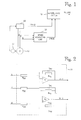
- FIG. 1 shows a block diagram of a system to which the invention may be applied.
- the arrangement is shown in connection with an inverter 20 and a motor 10 fed by the inverter.
- the use of the invention is not restricted to any particular type of inverter. Therefore, the structure of the inverter is not described in more detail in the following.
- the supply (not shown in the figure) of the inverter 20, the motor 10 controlled by it or the type of connections between them, such as the voltage level or the number of phases, does not bear significance to the basic idea of the invention either.
- the motor 10 may be, for example, an asynchronous motor, such as an induction motor, or a synchronous motor, such as a permanent magnet motor, or a reluctance motor, such as a synchronous reluctance motor.
- the inverter 20 feeds the motor 10 via a three-phase supply, the phase voltages of which are denoted by U, V and W.
- the inverter 20 may be a part of a frequency converter (not shown).
- the figure further shows a surveillance system 40, which obtains the rotation speed information on the motor primarily from the inverter 20, for example.
- the rotation speed information may be generated in the inverter 20, which feeds the motor 10 and thus typically knows the rotation speed of the motor 10. It is also feasible to use a tachometer 50, for example, which measures and transmits the rotation speed information on the motor 10 to the inverter 20, from which the information is further transmitted to the surveillance system 40.
- the speed rotation information of the motor 10 could also be transmitted directly from a possible tachometer 50 to the surveillance system 40.
- the surveillance system 40 may be a separate system, as in the figure, or it may be integrated in the inverter 20, for example, or a part of a frequency converter. This has no relevance to the basic idea of the invention, however.
- the purpose of the surveillance system 40 is generally to monitor and guarantee the safety of the motor drive 10, 20 in various situations and conditions of use and to give, in a case of failure, for example, a failure signal indicating the failure or to perform other measures, for example switching measures.
- the surveillance system 40 uses for instance rotation speed information on the motor 10, which it preferably obtains from at least two alternative sources.
- the safety functions enabled by the surveillance system 40 are system-specific and will thus not be explained in detail in this context. Further, the invention is not restricted to any particular type of system but an object of the invention is to provide one alternative manner of determining the rotation speed of the motor 10 in a situation where it is desirable to determine the rotation speed of the motor in at least two alternative ways.
- the rotation speed of the motor is determined in a second alternative manner in such a way that preferably the frequency of the voltage fed to the motor 10 by the inverter 20 is measured and the rotation speed of the motor 10 is estimated on the basis of the frequency measured in this way.
- Figure 1 shows a special speed measuring unit 30, by means of which the measurement and the estimation of the rotation speed can be carried out in accordance with one embodiment.
- the alternative, i.e. redundant, rotation speed information on the motor 10 can then be transmitted to the surveillance system 40, for instance, as shown in the figure.
- the speed measuring unit 30 or functionality corresponding to it may be a separate unit, as in the figure, or it may be integrated in the inverter 20, for example, or a part of a frequency converter.
- Units 31 to 37 are preferably included in the speed measuring unit 30. It is to be noted, however, that the invention is by no means restricted to the examples described in the following. It will be obvious to a person skilled in the art that the basic idea of the invention may also be implemented in alternative ways.
- FIG. 2 shows a connection diagram of a measuring arrangement 31 of phase to phase voltages in accordance with an embodiment.
- phase voltages U, V and W of the feed connection between the inverter 20 and the motor 10 are measured preferably by means of high-resistance measuring resistors R SU , Rsv and R SW .
- Phase to phase voltages U - V and W - V are further generated from the phase voltages U, V and W by means of amplification units A 1 and A 2 and, at the same time, the voltages are low-pass filtered by means of low-pass filters preferably formed of filter resistors R FU , R FV and R FW as well as of filter capacitors C FU , C FV and C FW .
- the values of the filter resistors R FU , R FV and R FW and filter capacitors C FU , C FV and C FW are preferably measured in such a way that the cut-off frequency of the low-pass filtering is so low (e.g. about 200 Hz) that pulse modulation is filtered off from the output voltage of the inverter.
- the frequency of the pulse modulation of the inverter is typically about 1 to 10 kHz.
- the phase to phase voltage between phases U and W could as well be measured and used.
- what are called integrators could also be used. However, this is not relevant to the basic idea of the invention.
- Figure 3 shows a block diagram of an arrangement for determining the frequency of the voltage fed to the motor 10 by the inverter 20 and further for estimating the rotation speed of the motor 10 on the basis of the phase to phase voltages in accordance with an embodiment.
- the two phase to phase voltages for instance U - V and W - V, obtained from the measuring arrangement 31, are first taken to a 3/2 coordinate converter 32, by means of which the phase to phase voltage signals are converted to x/y coordinates. From the signals obtained in this way, the inverse function of the tangent, i.e. atan, is calculated by means of a unit 33, whereby the result is the angle of the output voltage of the frequency converter 20.
- the angular value is further transmitted to a subtraction member 35 both directly and via a delay member 34.
- the delay member 34 delays the signal by a time period t.
- the subtraction member 35 subtracts the angular value and the delayed angular value from each other.
- the difference obtained in this way being divided by the time period t gives the rate of change of the output voltage angle of the frequency converter 20.
- the rate of change of the output voltage angle obtained in this way is preferably filtered in a unit 37, and the frequency of the output voltage of the frequency converter 20, i.e. the frequency of the voltage feeding the motor 10, corresponding to the angular speed, is determined and the rotation speed of the motor 10 is estimated.
- the rotation speed of the motor 10 can be estimated in a manner known as such on the basis of the frequency of the voltage feeding the motor 10, depending on the motor type.
- the rotation speed of an induction motor may also be estimated with this equation, although the rotation speed of the induction motor is further affected by slip ⁇ n. In several applications, however, the effect of the slip can be ignored and a sufficiently accurate speed estimate can still be obtained.
- the alternative estimate of the rotation speed of the motor 10 thus obtained is further transmitted from the speed measuring unit 30 to the surveillance system 40 or other required use.
- the speed measuring unit 30 or other possible equipment with which the rotation speed of the motor 10 or its estimate is determined may be implemented by means of one or more units.
- the term "unit" refers generally to a physical or logical entity, such as a physical device, a part of it or a software routine. The units may be physically separate or implemented as one entity.
- the equipment according to the embodiments of the invention may be implemented at least partly by means of a computer or corresponding signal processing equipment having suitable software.
- a computer or signal processing equipment preferably comprises at least a memory which provides a storage area made use of by arithmetic operations, and a processor, such as a general-purpose digital signal processor (DSP), performing the arithmetic operations.
- DSP general-purpose digital signal processor
- the measuring arrangement 31 is implemented by means of physical discrete components or the like, as shown in Figure 2 , for example.
- the low-pass filter functionality of the measuring arrangement 31, for example, or integrator functionality possibly used instead could be implemented by means of a computer or the like signal processing equipment and suitable software.
- the invention may be implemented in existing systems, such as in inverters and/or surveillance systems of motor drives, or discrete elements and devices may be used in a centralized or decentralized manner.
- Existing devices such as inverters, typically comprise a processor and a memory which may be utilized in implementing the functionality of the embodiments of the invention.
- the changes and assemblies required by the implementation of the embodiments of the invention may, at least partly, be taken care of by software routines, which, in turn, may be implemented as added or updated software routines.
- software routines which, in turn, may be implemented as added or updated software routines.
- the functionality of the invention is implemented by means of software, such software may be provided as a computer program product comprising a computer program code the execution of which in the computer causes the computer or the like equipment to perform the functionality according to the invention in accordance with the above-described embodiments.
- Such a computer code may be stored on a computer-readable medium, such as an appropriate memory means, for instance flash memory or disk memory, from where it is readable to a unit or units that execute the program code. Further, such a program code may be loaded to a unit or units executing the program code via a suitable data network, or it may replace or update a possibly existing program code.
- a computer-readable medium such as an appropriate memory means, for instance flash memory or disk memory
Landscapes
- Engineering & Computer Science (AREA)
- Power Engineering (AREA)
- Physics & Mathematics (AREA)
- General Physics & Mathematics (AREA)
- Control Of Ac Motors In General (AREA)
Abstract
A method and an arrangement for determining the rotation speed of a motor fed by an inverter, the arrangement comprising means (20, 30, 50) for determining the rotation speed of the motor (10) in at least two alternative manners, whereby the means for determining the rotation speed of the motor (10) comprise one of the at least two alternative manners of performance: means (30) for measuring the frequency of the voltage fed to the motor by the inverter (20); and means (30) for estimating the rotation speed of the motor on the basis of the measured frequency.
Description
- The invention relates to a method and an arrangement for determining the rotation speed of a motor fed by an inverter.
- An inverter is an electrical device which enables generation of voltage with changeable frequency. Typically, inverters are used in connection with motors for controlling them at a changing frequency. An inverter may also be a part of a frequency converter used for controlling a motor, for example.
- In connection with inverters and, in general, motor drives comprising inverters, various safety functions are generally applied, the purpose of which is to monitor and ensure the safety of the motor drives in different operating situations and conditions. Examples of safety functions according to recommendations include Safe Torque Off STO,
Safe Stop 1 SS1 and Safety Limited Speed SLS. - Implementing safety functions requires that the rotation speed of the motor be determined as reliably as possible. Typically, the rotation speed information on the motor is primarily obtained from the inverter controlling the motor. However, the rotation speed information obtained from the inverter alone does not necessarily guarantee the reliability of the safety functions, for example in a case where the inverter has failed in some way. Due to this, there is a need to arrange alternative redundant speed determination independent of the above-mentioned speed determination to implement the safety functions reliably.
- One way to determine the rotation speed of the motor independently of the inverter feeding it is to measure the rotation speed from the motor by means of a tachometer, i.e. a rev counter. A tachometer may be connected to a motor, for example to its shaft, either with a physical connection or by means of an optical connection, for example, without physical contact, thus determining the rotation speed of the motor.
- A problem relating to the determination of the rotation speed of a motor is that implementing the safety functions always requires an additional tachometer for each motor to be monitored, which increases the costs. Further, connecting an additional tachometer to the motor and/or positioning it in connection with a motor, as well as maintenance possibly required for the tachometer positioned in connection with the motor may be difficult in some conditions.
- An object of this invention is to provide a method and an apparatus implementing the method which avoid the above drawbacks or at least alleviate them. This object is achieved with a method, an arrangement, an inverter and a frequency converter which are characterized by what is stated in
independent claims - The invention is based on the idea of measuring, as an alternative determination manner of the rotation speed of a motor, the frequency of the voltage fed to the motor by an inverter and estimating the rotation speed of the motor on the basis of the frequency measured.
- An advantage of the solution according to the invention is that the alternative determination of the rotation speed of a motor does not require an additional tachometer but the speed may be estimated with sufficient accuracy by means of a simple and inexpensive arrangement. Furthermore, the solution according to the invention does not require modelling of the motor, whereby the size of the motor, for instance, does not affect the functioning of the solution.
- The invention will now be explained in greater detail in connection with preferred embodiments, referring to the attached drawings, of which:
-
Figure 1 shows a block diagram of a system to which the invention may be applied; -
Figure 2 shows a connection diagram of a measuring arrangement of phase to phase voltages in accordance with an embodiment; and -
Figure 3 shows a block diagram of an arrangement for estimating the rotation speed of a motor on the basis of phase to phase voltages in accordance with an embodiment. -
Figure 1 shows a block diagram of a system to which the invention may be applied. The arrangement is shown in connection with aninverter 20 and amotor 10 fed by the inverter. It is to be noted that the use of the invention is not restricted to any particular type of inverter. Therefore, the structure of the inverter is not described in more detail in the following. For example, the supply (not shown in the figure) of theinverter 20, themotor 10 controlled by it or the type of connections between them, such as the voltage level or the number of phases, does not bear significance to the basic idea of the invention either. Themotor 10 may be, for example, an asynchronous motor, such as an induction motor, or a synchronous motor, such as a permanent magnet motor, or a reluctance motor, such as a synchronous reluctance motor. - In the exemplary system of
Figure 1 , theinverter 20 feeds themotor 10 via a three-phase supply, the phase voltages of which are denoted by U, V and W. Theinverter 20 may be a part of a frequency converter (not shown). The figure further shows asurveillance system 40, which obtains the rotation speed information on the motor primarily from theinverter 20, for example. The rotation speed information may be generated in theinverter 20, which feeds themotor 10 and thus typically knows the rotation speed of themotor 10. It is also feasible to use atachometer 50, for example, which measures and transmits the rotation speed information on themotor 10 to theinverter 20, from which the information is further transmitted to thesurveillance system 40. The speed rotation information of themotor 10 could also be transmitted directly from apossible tachometer 50 to thesurveillance system 40. Thesurveillance system 40 may be a separate system, as in the figure, or it may be integrated in theinverter 20, for example, or a part of a frequency converter. This has no relevance to the basic idea of the invention, however. The purpose of thesurveillance system 40 is generally to monitor and guarantee the safety of themotor drive surveillance system 40 uses for instance rotation speed information on themotor 10, which it preferably obtains from at least two alternative sources. The safety functions enabled by thesurveillance system 40 are system-specific and will thus not be explained in detail in this context. Further, the invention is not restricted to any particular type of system but an object of the invention is to provide one alternative manner of determining the rotation speed of themotor 10 in a situation where it is desirable to determine the rotation speed of the motor in at least two alternative ways. - In accordance with the invention, the rotation speed of the motor is determined in a second alternative manner in such a way that preferably the frequency of the voltage fed to the
motor 10 by theinverter 20 is measured and the rotation speed of themotor 10 is estimated on the basis of the frequency measured in this way.Figure 1 shows a specialspeed measuring unit 30, by means of which the measurement and the estimation of the rotation speed can be carried out in accordance with one embodiment. The alternative, i.e. redundant, rotation speed information on themotor 10 can then be transmitted to thesurveillance system 40, for instance, as shown in the figure. Thespeed measuring unit 30 or functionality corresponding to it may be a separate unit, as in the figure, or it may be integrated in theinverter 20, for example, or a part of a frequency converter. The following describes, by way of example, how the frequency of the voltage fed to themotor 10 by theinverter 20 can be measured and the speed rotation of themotor 10 be estimated in accordance with some embodiments.Units 31 to 37, described in the following example, are preferably included in thespeed measuring unit 30. It is to be noted, however, that the invention is by no means restricted to the examples described in the following. It will be obvious to a person skilled in the art that the basic idea of the invention may also be implemented in alternative ways. -
Figure 2 shows a connection diagram of ameasuring arrangement 31 of phase to phase voltages in accordance with an embodiment. In accordance with the example of the figure, phase voltages U, V and W of the feed connection between theinverter 20 and themotor 10 are measured preferably by means of high-resistance measuring resistors RSU, Rsv and RSW. Phase to phase voltages U - V and W - V are further generated from the phase voltages U, V and W by means of amplification units A1 and A2 and, at the same time, the voltages are low-pass filtered by means of low-pass filters preferably formed of filter resistors RFU, RFV and RFW as well as of filter capacitors CFU, CFV and CFW. The values of the filter resistors RFU, RFV and RFW and filter capacitors CFU, CFV and CFW are preferably measured in such a way that the cut-off frequency of the low-pass filtering is so low (e.g. about 200 Hz) that pulse modulation is filtered off from the output voltage of the inverter. The frequency of the pulse modulation of the inverter is typically about 1 to 10 kHz. Instead of one of the phase to phase voltages U - V and W - V, the phase to phase voltage between phases U and W could as well be measured and used. Instead of low-pass filters included inmeasurement configuration 31 inFigure 2 , what are called integrators could also be used. However, this is not relevant to the basic idea of the invention. -
Figure 3 shows a block diagram of an arrangement for determining the frequency of the voltage fed to themotor 10 by theinverter 20 and further for estimating the rotation speed of themotor 10 on the basis of the phase to phase voltages in accordance with an embodiment. The two phase to phase voltages, for instance U - V and W - V, obtained from themeasuring arrangement 31, are first taken to a 3/2coordinate converter 32, by means of which the phase to phase voltage signals are converted to x/y coordinates. From the signals obtained in this way, the inverse function of the tangent, i.e. atan, is calculated by means of aunit 33, whereby the result is the angle of the output voltage of thefrequency converter 20. The angular value is further transmitted to asubtraction member 35 both directly and via adelay member 34. Thedelay member 34 delays the signal by a time period t. Thesubtraction member 35 subtracts the angular value and the delayed angular value from each other. The difference obtained in this way being divided by the time period t gives the rate of change of the output voltage angle of thefrequency converter 20. The rate of change of the output voltage angle obtained in this way is preferably filtered in aunit 37, and the frequency of the output voltage of thefrequency converter 20, i.e. the frequency of the voltage feeding themotor 10, corresponding to the angular speed, is determined and the rotation speed of themotor 10 is estimated. The rotation speed of themotor 10 can be estimated in a manner known as such on the basis of the frequency of the voltage feeding themotor 10, depending on the motor type. For example, the rotation speed of a synchronous motor (synchronous speed) n (revolutions per minute) may be calculated with equation n = f/p, where f is the frequency of the feeding voltage and p is the number of pairs of poles of the motor. The rotation speed of an induction motor, for example, may also be estimated with this equation, although the rotation speed of the induction motor is further affected by slip Δn. In several applications, however, the effect of the slip can be ignored and a sufficiently accurate speed estimate can still be obtained. The alternative estimate of the rotation speed of themotor 10 thus obtained is further transmitted from thespeed measuring unit 30 to thesurveillance system 40 or other required use. - The
speed measuring unit 30 or other possible equipment with which the rotation speed of themotor 10 or its estimate is determined may be implemented by means of one or more units. The term "unit" refers generally to a physical or logical entity, such as a physical device, a part of it or a software routine. The units may be physically separate or implemented as one entity. The equipment according to the embodiments of the invention may be implemented at least partly by means of a computer or corresponding signal processing equipment having suitable software. Such a computer or signal processing equipment preferably comprises at least a memory which provides a storage area made use of by arithmetic operations, and a processor, such as a general-purpose digital signal processor (DSP), performing the arithmetic operations. It is also feasible to use specific integrated circuits, such as ASIC (Application Specific Integrated Circuit) or other components and devices for implementing the functionality of the invention in accordance with different embodiments. Preferably, the measuringarrangement 31 is implemented by means of physical discrete components or the like, as shown inFigure 2 , for example. However, the low-pass filter functionality of the measuringarrangement 31, for example, or integrator functionality possibly used instead could be implemented by means of a computer or the like signal processing equipment and suitable software. The arrangement ofFigure 3 for estimating the rotation speed of themotor 10 on the basis of the phase to phase voltages, comprisingunits 32 to 37, or an arrangement with corresponding functionality is preferably implemented by means of a computer or the like signal processing equipment provided with suitable software, but an implementation using discrete components at least partly is also feasible. - The invention may be implemented in existing systems, such as in inverters and/or surveillance systems of motor drives, or discrete elements and devices may be used in a centralized or decentralized manner. Existing devices, such as inverters, typically comprise a processor and a memory which may be utilized in implementing the functionality of the embodiments of the invention. Thus, the changes and assemblies required by the implementation of the embodiments of the invention may, at least partly, be taken care of by software routines, which, in turn, may be implemented as added or updated software routines. If the functionality of the invention is implemented by means of software, such software may be provided as a computer program product comprising a computer program code the execution of which in the computer causes the computer or the like equipment to perform the functionality according to the invention in accordance with the above-described embodiments. Such a computer code may be stored on a computer-readable medium, such as an appropriate memory means, for instance flash memory or disk memory, from where it is readable to a unit or units that execute the program code. Further, such a program code may be loaded to a unit or units executing the program code via a suitable data network, or it may replace or update a possibly existing program code.
- It will be obvious to a person skilled in the art that the basic idea of the invention may be implemented in a plurality of ways. The invention and its embodiments are thus not restricted to the examples described but may vary within the scope of the claims.
Claims (10)
- A method for determining the rotation speed of a motor fed by an inverter, the method comprising:determining the rotation speed of the motor in at least two alternative manners, characterized by one of the at least two alternative manners comprising:measuring the frequency of a voltage fed to the motor by an inverter; andestimating the rotation speed of the motor on the basis of the measured frequency.
- A method according to claim 1, characterized by a feed connection between the inverter and the motor having three phases, whereby the measurement of the frequency of the voltage fed to the motor by the inverter comprises:measuring two phase to phase voltages of the feed connection between the inverter and the motor;determining, on the basis of the measured phase to phase voltages, the rate of change of the angle of the voltage fed to the motor by the inverter; anddetermining the frequency corresponding to the rate of change of the angle.
- A method according to claim 2, characterized by the measured two phase to phase voltages of the feed connection between the inverter and the motor being low-pass filtered to remove the modulation frequency, whereby the rate of change of the angle of the voltage fed to the motor by the inverter is determined on the basis of the low-pass filtered phase to phase voltages.
- A method according to claim 1, 2 or 3, characterized by the motor being an induction motor or a synchronous motor.
- An arrangement for determining the rotation speed of a motor fed by an inverter, the arrangement comprising:means (20, 30, 50) for determining the rotation speed of the motor (10) in at least two alternative manners, characterized in that the means for determining the rotation speed of the motor (10) comprise for performing one of the at least two alternative manners:means (30; 31, 32, 33, 34, 35, 36, 37) for measuring the frequency of the voltage fed to the motor by the inverter; andmeans (30; 37) for estimating the rotation speed of the motor on the basis of the measured frequency.
- An arrangement according to claim 5, characterized in that the feed connection between the inverter (20) and the motor (10) has three phases, whereby the means for measuring the frequency of the voltage fed to the motor by the inverter comprise:means (31) for measuring two phase to phase voltages of the feed connection between the inverter (20) and the motor (10);means (32, 33, 34, 35, 36) for determining the rate of change of the angle of the voltage fed to the motor by the inverter on the basis of the measured phase to phase voltages; andmeans (37) for determining the frequency corresponding to the rate of change of the angle.
- An arrangement according to claim 6, characterized in that the means (31) for measuring two phase to phase voltages of the feed connection between the inverter (20) and the motor (10) comprise means (RFU, RFV, RFW, CFU, CFV, CFW) for low-pass filtering the measured two phase to phase voltages of the feed connection between the inverter and the motor.
- An arrangement according to claim 5, 6 or 7, characterized in that the motor (10) is an induction motor or a synchronous motor.
- An inverter comprising an arrangement according to any one of claims 5 to 8.
- A frequency converter comprising an arrangement according to any one of claims 5 to 8.
Applications Claiming Priority (1)
| Application Number | Priority Date | Filing Date | Title |
|---|---|---|---|
| FI20085826A FI121721B (en) | 2008-09-04 | 2008-09-04 | Method and arrangement for determining engine speed |
Publications (1)
| Publication Number | Publication Date |
|---|---|
| EP2161824A1 true EP2161824A1 (en) | 2010-03-10 |
Family
ID=39852219
Family Applications (1)
| Application Number | Title | Priority Date | Filing Date |
|---|---|---|---|
| EP09168774A Withdrawn EP2161824A1 (en) | 2008-09-04 | 2009-08-27 | Method and arrangement for determining rotation speed of a motor |
Country Status (4)
| Country | Link |
|---|---|
| US (1) | US8400087B2 (en) |
| EP (1) | EP2161824A1 (en) |
| CN (1) | CN101666810B (en) |
| FI (1) | FI121721B (en) |
Cited By (1)
| Publication number | Priority date | Publication date | Assignee | Title |
|---|---|---|---|---|
| CN106006342A (en) * | 2016-08-01 | 2016-10-12 | 广东工业大学 | Control method and method for switching power grid driving of escalator into variable frequency driving |
Families Citing this family (6)
| Publication number | Priority date | Publication date | Assignee | Title |
|---|---|---|---|---|
| EP2632653B1 (en) * | 2010-10-28 | 2014-06-11 | ABB Research Ltd. | Method and apparatus for monitoring and limiting the velocity of an industrial robot |
| US8459195B2 (en) * | 2011-04-28 | 2013-06-11 | Michael H. IRVING | Self load sensing circuit board controller diaphragm pump |
| CN107037230B (en) * | 2017-04-17 | 2019-06-18 | 广西防城港核电有限公司 | A nuclear power plant main pump rotational speed active and standby detection signal processing method and device, rack |
| CN110470857B (en) * | 2019-09-08 | 2021-04-13 | 陕西航空电气有限责任公司 | Rotating speed detection method suitable for aviation power system generator |
| CN110501580A (en) * | 2019-09-25 | 2019-11-26 | 潍柴动力股份有限公司 | A kind of Phase Faults method and apparatus |
| CN116298368A (en) * | 2022-11-24 | 2023-06-23 | 国网内蒙古东部电力有限公司电力科学研究院 | A real-time monitoring device and working method for the speed of the motor controller based on the frequency conversion voltage |
Citations (6)
| Publication number | Priority date | Publication date | Assignee | Title |
|---|---|---|---|---|
| US4466052A (en) * | 1981-12-14 | 1984-08-14 | Thrap Guy C | Programmable DC-TO-AC voltage converter |
| US4978895A (en) * | 1988-10-17 | 1990-12-18 | Schwarz Marcos G | Electronic control circuit for brushless direct current motor |
| US20040046519A1 (en) * | 2002-09-11 | 2004-03-11 | Ford Global Technologies, Inc. | Diagnostic strategy for an electric motor using sensorless control and a position sensor |
| US20040052217A1 (en) * | 2002-09-16 | 2004-03-18 | Anghel Cristian E. | Position sensor emulator for a synchronous motor/generator |
| US20040061472A1 (en) * | 2002-09-26 | 2004-04-01 | Lg Electronics Inc. | Apparatus for measuring magnetic flux of synchronous reluctance motor and sensorless control system for the same motor |
| WO2008081509A1 (en) * | 2006-12-27 | 2008-07-10 | Mitsubishi Electric Corporation | Drive controller of electrically driven vehicle |
Family Cites Families (10)
| Publication number | Priority date | Publication date | Assignee | Title |
|---|---|---|---|---|
| DE2203320A1 (en) * | 1972-01-25 | 1973-08-02 | Daimler Benz Ag | DEVICE FOR THE FORMATION AND PROCESSING OF SPEED SIGNALS IN VEHICLES |
| US4044285A (en) * | 1975-08-19 | 1977-08-23 | General Electric Company | Method and apparatus for controlling variable speed, controlled current induction motor drive systems |
| US5646499A (en) * | 1994-08-25 | 1997-07-08 | Matsushita Electric Industrial Co.,Ltd. | Inverter control apparatus |
| DE19621046A1 (en) * | 1996-05-24 | 1997-11-27 | Skf Gmbh | Method and device for measuring the output torque |
| JP3982861B2 (en) | 1996-12-13 | 2007-09-26 | オリエンタルモーター株式会社 | Fan motor with rotation abnormality detector |
| US5754026A (en) * | 1997-04-04 | 1998-05-19 | Ford Global Technologies, Inc. | Induction motor control method |
| US5898287A (en) * | 1997-07-23 | 1999-04-27 | Technicore, Inc. | Slip controlled induction motor using variable frequency transducer and method for controlling slip |
| CN1215170A (en) * | 1997-10-20 | 1999-04-28 | 建准电机工业股份有限公司 | DC motor speed measuring device |
| JP2004222460A (en) | 2003-01-17 | 2004-08-05 | Fumito Komatsu | Synchronous motor |
| US7049778B2 (en) * | 2004-02-09 | 2006-05-23 | Nippon Yusoki Co., Ltd. | Inverter control apparatus and inverter control method |
-
2008
- 2008-09-04 FI FI20085826A patent/FI121721B/en active IP Right Grant
-
2009
- 2009-08-26 US US12/548,061 patent/US8400087B2/en active Active
- 2009-08-27 EP EP09168774A patent/EP2161824A1/en not_active Withdrawn
- 2009-09-03 CN CN200910172917.9A patent/CN101666810B/en active Active
Patent Citations (6)
| Publication number | Priority date | Publication date | Assignee | Title |
|---|---|---|---|---|
| US4466052A (en) * | 1981-12-14 | 1984-08-14 | Thrap Guy C | Programmable DC-TO-AC voltage converter |
| US4978895A (en) * | 1988-10-17 | 1990-12-18 | Schwarz Marcos G | Electronic control circuit for brushless direct current motor |
| US20040046519A1 (en) * | 2002-09-11 | 2004-03-11 | Ford Global Technologies, Inc. | Diagnostic strategy for an electric motor using sensorless control and a position sensor |
| US20040052217A1 (en) * | 2002-09-16 | 2004-03-18 | Anghel Cristian E. | Position sensor emulator for a synchronous motor/generator |
| US20040061472A1 (en) * | 2002-09-26 | 2004-04-01 | Lg Electronics Inc. | Apparatus for measuring magnetic flux of synchronous reluctance motor and sensorless control system for the same motor |
| WO2008081509A1 (en) * | 2006-12-27 | 2008-07-10 | Mitsubishi Electric Corporation | Drive controller of electrically driven vehicle |
Cited By (1)
| Publication number | Priority date | Publication date | Assignee | Title |
|---|---|---|---|---|
| CN106006342A (en) * | 2016-08-01 | 2016-10-12 | 广东工业大学 | Control method and method for switching power grid driving of escalator into variable frequency driving |
Also Published As
| Publication number | Publication date |
|---|---|
| FI121721B (en) | 2011-03-15 |
| CN101666810B (en) | 2014-10-29 |
| CN101666810A (en) | 2010-03-10 |
| FI20085826A0 (en) | 2008-09-04 |
| FI20085826L (en) | 2010-03-05 |
| US8400087B2 (en) | 2013-03-19 |
| US20100052582A1 (en) | 2010-03-04 |
Similar Documents
| Publication | Publication Date | Title |
|---|---|---|
| US8400087B2 (en) | Method and arrangement for determining rotation speed of a motor | |
| CN101750512B (en) | Method and apparatus for estimating rotation speed of electric motor | |
| US9866158B2 (en) | Method and arrangement for monitoring a permanently excited synchronous machine | |
| CN101385234A (en) | motor control | |
| CN104734580A (en) | Dual-redundancy control method and system of brushless motor | |
| CN106664050A (en) | Method for determining a position and/or change in position of a hydraulic pump of a motor vehicle brake system and motor vehicle brake system | |
| JP6967470B2 (en) | Control device | |
| CN112350626B (en) | Method and device for determining the rotational speed and the rotational angle of a motor shaft of a DC motor | |
| JP4797096B2 (en) | Stepping motor rotation angle detection device | |
| KR20110016573A (en) | Rotor position sensor | |
| US12504734B2 (en) | Systems and methods for a resolver and motor control with enhanced speed and direction monitoring | |
| EP3477846B1 (en) | Method for determining a measuring offset of a rotor position sensor, controller unit for an electric machine and electric machine for a vehicle | |
| JP2003319682A (en) | Control device for permanent magnet synchronous motor | |
| JP2006033903A (en) | Motor control device | |
| EP3244528B1 (en) | Power conversion device and control method for power conversion device | |
| JP2020005340A (en) | Motor controller and control method | |
| KR20140048581A (en) | Device for detecting error of sensorless motor using bemf signal | |
| Dobra et al. | Model based fault detection for electrical drives with BLDC motor | |
| JPWO2018216149A1 (en) | Rotation angle detection device and AC rotary machine control device | |
| KR20190001984A (en) | Method and system for estimating a position of rotator in electric motor | |
| JP2007089386A (en) | Redundant rotation speed monitoring device | |
| CN115459640B (en) | Method and device for controlling brushless direct current motor in position-free mode | |
| WO2021176761A1 (en) | Device monitoring device and device monitoring method | |
| KR19990001541A (en) | Speed detection method and device | |
| WO2015092463A1 (en) | Method for controlling an electric motor and sensor unit for implementing such a method |
Legal Events
| Date | Code | Title | Description |
|---|---|---|---|
| PUAI | Public reference made under article 153(3) epc to a published international application that has entered the european phase |
Free format text: ORIGINAL CODE: 0009012 |
|
| AK | Designated contracting states |
Kind code of ref document: A1 Designated state(s): AT BE BG CH CY CZ DE DK EE ES FI FR GB GR HR HU IE IS IT LI LT LU LV MC MK MT NL NO PL PT RO SE SI SK SM TR |
|
| AX | Request for extension of the european patent |
Extension state: AL BA RS |
|
| 17P | Request for examination filed |
Effective date: 20100325 |
|
| 17Q | First examination report despatched |
Effective date: 20100420 |
|
| STAA | Information on the status of an ep patent application or granted ep patent |
Free format text: STATUS: THE APPLICATION IS DEEMED TO BE WITHDRAWN |
|
| 18D | Application deemed to be withdrawn |
Effective date: 20180320 |