EP2161797A2 - Figure eight fiber laser for ultrashort pulse generation - Google Patents
Figure eight fiber laser for ultrashort pulse generation Download PDFInfo
- Publication number
- EP2161797A2 EP2161797A2 EP09011232A EP09011232A EP2161797A2 EP 2161797 A2 EP2161797 A2 EP 2161797A2 EP 09011232 A EP09011232 A EP 09011232A EP 09011232 A EP09011232 A EP 09011232A EP 2161797 A2 EP2161797 A2 EP 2161797A2
- Authority
- EP
- European Patent Office
- Prior art keywords
- polarization
- fiber
- maintaining
- loop
- optical
- Prior art date
- Legal status (The legal status is an assumption and is not a legal conclusion. Google has not performed a legal analysis and makes no representation as to the accuracy of the status listed.)
- Granted
Links
Images


Classifications
-
- H—ELECTRICITY
- H01—ELECTRIC ELEMENTS
- H01S—DEVICES USING THE PROCESS OF LIGHT AMPLIFICATION BY STIMULATED EMISSION OF RADIATION [LASER] TO AMPLIFY OR GENERATE LIGHT; DEVICES USING STIMULATED EMISSION OF ELECTROMAGNETIC RADIATION IN WAVE RANGES OTHER THAN OPTICAL
- H01S3/00—Lasers, i.e. devices using stimulated emission of electromagnetic radiation in the infrared, visible or ultraviolet wave range
- H01S3/05—Construction or shape of optical resonators; Accommodation of active medium therein; Shape of active medium
- H01S3/06—Construction or shape of active medium
- H01S3/063—Waveguide lasers, i.e. whereby the dimensions of the waveguide are of the order of the light wavelength
- H01S3/067—Fibre lasers
- H01S3/06791—Fibre ring lasers
-
- H—ELECTRICITY
- H01—ELECTRIC ELEMENTS
- H01S—DEVICES USING THE PROCESS OF LIGHT AMPLIFICATION BY STIMULATED EMISSION OF RADIATION [LASER] TO AMPLIFY OR GENERATE LIGHT; DEVICES USING STIMULATED EMISSION OF ELECTROMAGNETIC RADIATION IN WAVE RANGES OTHER THAN OPTICAL
- H01S3/00—Lasers, i.e. devices using stimulated emission of electromagnetic radiation in the infrared, visible or ultraviolet wave range
- H01S3/10—Controlling the intensity, frequency, phase, polarisation or direction of the emitted radiation, e.g. switching, gating, modulating or demodulating
- H01S3/106—Controlling the intensity, frequency, phase, polarisation or direction of the emitted radiation, e.g. switching, gating, modulating or demodulating by controlling devices placed within the cavity
-
- H—ELECTRICITY
- H01—ELECTRIC ELEMENTS
- H01S—DEVICES USING THE PROCESS OF LIGHT AMPLIFICATION BY STIMULATED EMISSION OF RADIATION [LASER] TO AMPLIFY OR GENERATE LIGHT; DEVICES USING STIMULATED EMISSION OF ELECTROMAGNETIC RADIATION IN WAVE RANGES OTHER THAN OPTICAL
- H01S3/00—Lasers, i.e. devices using stimulated emission of electromagnetic radiation in the infrared, visible or ultraviolet wave range
- H01S3/10—Controlling the intensity, frequency, phase, polarisation or direction of the emitted radiation, e.g. switching, gating, modulating or demodulating
- H01S3/11—Mode locking; Q-switching; Other giant-pulse techniques, e.g. cavity dumping
- H01S3/1106—Mode locking
- H01S3/1112—Passive mode locking
-
- H—ELECTRICITY
- H01—ELECTRIC ELEMENTS
- H01S—DEVICES USING THE PROCESS OF LIGHT AMPLIFICATION BY STIMULATED EMISSION OF RADIATION [LASER] TO AMPLIFY OR GENERATE LIGHT; DEVICES USING STIMULATED EMISSION OF ELECTROMAGNETIC RADIATION IN WAVE RANGES OTHER THAN OPTICAL
- H01S3/00—Lasers, i.e. devices using stimulated emission of electromagnetic radiation in the infrared, visible or ultraviolet wave range
- H01S3/05—Construction or shape of optical resonators; Accommodation of active medium therein; Shape of active medium
- H01S3/06—Construction or shape of active medium
- H01S3/063—Waveguide lasers, i.e. whereby the dimensions of the waveguide are of the order of the light wavelength
- H01S3/067—Fibre lasers
- H01S3/06708—Constructional details of the fibre, e.g. compositions, cross-section, shape or tapering
- H01S3/06712—Polarising fibre; Polariser
-
- H—ELECTRICITY
- H01—ELECTRIC ELEMENTS
- H01S—DEVICES USING THE PROCESS OF LIGHT AMPLIFICATION BY STIMULATED EMISSION OF RADIATION [LASER] TO AMPLIFY OR GENERATE LIGHT; DEVICES USING STIMULATED EMISSION OF ELECTROMAGNETIC RADIATION IN WAVE RANGES OTHER THAN OPTICAL
- H01S3/00—Lasers, i.e. devices using stimulated emission of electromagnetic radiation in the infrared, visible or ultraviolet wave range
- H01S3/05—Construction or shape of optical resonators; Accommodation of active medium therein; Shape of active medium
- H01S3/06—Construction or shape of active medium
- H01S3/07—Construction or shape of active medium consisting of a plurality of parts, e.g. segments
-
- H—ELECTRICITY
- H01—ELECTRIC ELEMENTS
- H01S—DEVICES USING THE PROCESS OF LIGHT AMPLIFICATION BY STIMULATED EMISSION OF RADIATION [LASER] TO AMPLIFY OR GENERATE LIGHT; DEVICES USING STIMULATED EMISSION OF ELECTROMAGNETIC RADIATION IN WAVE RANGES OTHER THAN OPTICAL
- H01S3/00—Lasers, i.e. devices using stimulated emission of electromagnetic radiation in the infrared, visible or ultraviolet wave range
- H01S3/10—Controlling the intensity, frequency, phase, polarisation or direction of the emitted radiation, e.g. switching, gating, modulating or demodulating
- H01S3/106—Controlling the intensity, frequency, phase, polarisation or direction of the emitted radiation, e.g. switching, gating, modulating or demodulating by controlling devices placed within the cavity
- H01S3/1061—Controlling the intensity, frequency, phase, polarisation or direction of the emitted radiation, e.g. switching, gating, modulating or demodulating by controlling devices placed within the cavity using a variable absorption device
-
- H—ELECTRICITY
- H01—ELECTRIC ELEMENTS
- H01S—DEVICES USING THE PROCESS OF LIGHT AMPLIFICATION BY STIMULATED EMISSION OF RADIATION [LASER] TO AMPLIFY OR GENERATE LIGHT; DEVICES USING STIMULATED EMISSION OF ELECTROMAGNETIC RADIATION IN WAVE RANGES OTHER THAN OPTICAL
- H01S3/00—Lasers, i.e. devices using stimulated emission of electromagnetic radiation in the infrared, visible or ultraviolet wave range
- H01S3/14—Lasers, i.e. devices using stimulated emission of electromagnetic radiation in the infrared, visible or ultraviolet wave range characterised by the material used as the active medium
- H01S3/16—Solid materials
- H01S3/1601—Solid materials characterised by an active (lasing) ion
- H01S3/1603—Solid materials characterised by an active (lasing) ion rare earth
- H01S3/1608—Solid materials characterised by an active (lasing) ion rare earth erbium
Definitions
- the present invention relates to a figure eight mode-locked fiber laser and, more particularly, to a polarization maintaining figure eight (PMFE) laser with additional bias introduced into the bi-directional loop to generate ultrashort (fs) pulses of a desired spectral width.
- PMFE polarization maintaining figure eight
- Ultra short optical pulses can be used in a number of applications including optical information processing and data communication, optical probing with high temporal resolution, laser surgery, and material processing.
- optical data communication with data rates up to 2.5 Gbit/s or higher demand compact, ultra fast light sources with low maintenance, high reliability, and low cost.
- Fiber lasers have been developed as a new generation of compact, inexpensive and robust light sources.
- a fiber laser is an optically-pumped resonator with a section of doped-fiber as the gain medium. As the gain exceeds the total optical loss in the resonator, a laser oscillation can be generated.
- Many different dopants can be used to achieve laser oscillations at different wavelengths.
- Atomic transitions in rare-earth ions can be used to produce lasers from visible wavelengths to far infrared wavelengths (e.g., 0.45 ⁇ m - 3.5 ⁇ m). Erbium-doped fiber lasers for producing optical pulses at 1.55 ⁇ m are particularly useful for optical fiber communication since the optical loss in commonly used silica fibers is minimum at about 1.55 ⁇ m.
- Mode-locked fiber lasers can use various cavity configurations such as linear, ring, and figure-eight geometries. See, for example, US Patent 5,008,887 issued to Kafka et al. on April 16, 1991 and US Patent 5,513,194 issued to Tamura et al. on April 30, 1996 .
- a mode-locked fiber laser is configured to have multiple longitudinal modes that simultaneously oscillate.
- a mode-locking mechanism is implemented in the resonator to synchronize the phases of different modes in such a way that the phase difference between any two adjacent modes is a constant. These phase-locked modes constructively add to one another to produce a short pulse.
- Active mode locking modulates either the amplitude or the phase of the intra-cavity optical field at a frequency equal to one or a multiplicity of the mode spacing.
- Active mode locking can be implemented by using intra-cavity electro-optic and acousto-optic modulators.
- passive mode locking uses at least one nonlinear optical element inside the resonator to produce an intensity-dependent response to an optical pulse so that the pulse width of the optical pulse exiting the nonlinear element is reduced.
- passive mode locking can be used advantageously to produce ultra short light sources.
- Commonly-used passive mode locking techniques include saturable absorbers, figure-eight lasers and intensity-dependent nonlinear polarization rotation.
- the nonlinear element that provides an intensity-dependent response takes the form of a nonlinear optical loop mirror.
- Mode-locked fiber lasers typically require a balance of "normal” (i.e., negative) and “anomalous” (i.e., positive) dispersion fibers to achieve ultra-short pulses.
- US Patent Application Serial No. 11/985,442 which is assigned to the assignee of this application and herein incorporated by reference, discloses the first known PMFE laser utilizing dispersion management to produce ultra-short pulses.
- An external modulating signal source (either phase or amplitude) is utilized with this PMFE arrangement to trigger the lasing process. Once stimulated, the external signal source can be removed and the PMFE laser will be mode-locked and sustain operation.
- the present invention relates to a PMFE fiber laser and, more particularly, to a PMFE fiber laser incorporating additional optical bias in the bi-directional loop to create the necessary shift between counter propagating signals to create ultrashort output pulses, on the order of about 100 femtoseconds.
- a PMFE fiber laser is modified to incorporate an additional variable loss component in the bi-directional loop to create an optical bias condition sufficient to generate ultrashort optical pulses.
- the bi-directional loop in the PMFE laser provides the ultrafast saturable absorption which leads to passive modelocking by providing an intensity-dependent transmission.
- bias in this loop By incorporating bias in this loop, a phase difference will accumulate between the counter propagating fields in the loop sufficient to generate the desired ultrashort output pulses.
- the bias is introduced in the form of an asymmetric splitter between the two loops in the laser.
- An additional loss element (which may be adjustable, such as a variable optical attenuator (VOA) or similar attenuation element) can also be inserted in the bi-directional loop as the bias component. In operation, the degree of attenuation may be adjusted during fabrication until optimum modelocking is achieved.
- the conventional input/output coupler for the PMFE laser can be moved to the bi-directional loop and thus add the required bias to the arrangement. The incorporation of various splice and/or bending losses in the bi-directional loop may be sufficient to allow for ultrashort pulse generation.
- bias in the bi-directional loop include, but are not limited to, imparting physical/mechanical changes to the bi-directional fiber (strain, stress, temperature, etc.).
- FIG. 1 illustrates a prior art figure eight fiber laser, using external/mechanical polarization controllers to maintain the polarization of the propagating signal and introduce the bias required to generate ultrashort output pulses;
- FIG. 2 illustrates a PMFE fiber laser of the prior art, which eliminates the need for external polarization control elements, but is limited in terms of generating ultrashort optical pulses;
- FIG. 3 shows an exemplary PMFE fiber laser formed in accordance with the present invention to generate ultrashort optical pulses by intentionally including a loss element within the bi-directional loop of the laser;
- FIG. 4 illustrates one particular embodiment of the present invention, utilizing an asymmetric power splitter as the optical loss element
- FIG. 5 is a plot of the mode-locked spectrum of the PMFE fiber laser of the embodiment of FIG. 4 of the present invention.
- FIG. 6 is a plot of the autocorrelation function of output pulses from the embodiment of FIG. 4 ;
- FIG. 7 is another embodiment of the present invention, utilizing a variable optical attenuator (VOA) in the bi-directional loop to generate ultrashort pulses;
- VOA variable optical attenuator
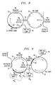
- FIG. 8 shows yet another embodiment of the present invention, using an output coupler to create asymmetry in the loop configuration
- FIG. 9 illustrates an embodiment of the present invention where a second fiber amplifier is used to create the desired bias situation in the bi-directional loop.
- a prior art figure-eight fiber laser 1 includes a first loop 2 of single mode fiber, formed to include a section 3 of doped (normal dispersion) fiber to provide amplification. Typically, the length of doped fiber section 3 is selected based on the desired center operating wavelength of the laser. Erbium is one of the conventional rare-earth material choices for this type of fiber laser.
- First fiber loop 2 is coupled to a second loop 4 of single mode fiber through a 50:50 directional coupler 5.
- the single-mode fiber (SMF) used in the cavity typically exhibits anomalous (positive) dispersion at the desired 1550 nm operating wavelength used for communication systems.
- the combination of loops 2 and 4 with coupler 5 thus forms the "figure-eight" structure.
- a source 6 of pump light is coupled into first loop 2 via a coupler 7 (which may comprise, in one case, a wavelength division multiplexing element) to provide the light input for the structure.
- first loop 2 the light amplified within section 3 of first loop 2 will continue to circulate around loop 2, exhibiting an increase in gain each time, with about half the signal power coupled into loop 4 during each pass.
- An isolator 8 in loop 4 will prevent any counter-propagating signal from being established within second loop 4.
- An output directional coupler 9 is also included in second loop 4 and is used to out-couple a fraction of the mode-locked laser output signal. Depending on the gain of the fiber and loss of other components in the cavity, this fraction can vary from a few percent to more than 50%, allowing for the figure-eight structure to remain passively mode-locked and continue to provide an output signal.
- a pair of mechanical polarization controllers 10 and 11 are disposed within loops 2 and 4 and used to maintain a consistent polarization state for the propagating signal.
- polarization controllers 10 and 11 have been used in the past to tune the loop bias in a manner that allowed for ultrashort pulses (on the order of 100 femtoseconds) to be generated.
- FIG. 2 illustrates an exemplary PMFE fiber laser 20 as disclosed in our coassigned application referenced above.
- the need for mechanical polarization controllers has been eliminated by utilizing polarization maintaining fiber to form the loops.
- an initial "boost" in modulation (either amplitude or phase) may be required for the arrangement to enter the regime of passive mode locking. All of these aspects of a PMFE are shown with particularity in the arrangement of FIG. 2 .
- passively mode-locked PMFE fiber laser 20 comprises a first loop 22 of polarization maintaining, single mode fiber (PM-SMF) exhibiting the anomalous dispersion characteristic of single mode fiber.
- a section of erbium-doped (Er-doped), polarization maintaining fiber 24 is coupled to the PM-SMF to complete the geometry of first loop 22. Erbium-doped, polarization maintaining fiber 24 exhibits normal dispersion.
- a first input coupler 26 (also polarization maintaining) is used to inject a pump light signal from a pump source 28 into Er-doped fiber 24.
- the wavelength of pump source 28 in this case illustrated as 980 nm, is selected to provide amplification utilizing the Er dopant.
- Laser 20 further comprises a second loop 36, also formed of polarization maintaining, single mode fiber (again, of anomalous, positive dispersion characteristic).
- a polarization maintaining 50:50 optical splitter 38 is used to couple first loop 22 to second loop 36 and thus direct the propagating signal between the two loops.
- a polarization maintaining in-line optical isolator 40 is included within second loop 36 to prevent the counter-propagation of the signal through the system.
- a polarization maintaining 50:50 output coupler 42 is provided to out-couple the mode-locked pulse signal from fiber laser 20.
- a polarization-maintaining modulator 44 is disposed along second loop 36 and is driven by an external drive source 46. The introduction of the external signal is sufficient to perturb the steady-state condition of laser 20 and initiate mode locking. Once mode locking has been sustained, drive 46 is disconnected from the system and passive mode-locking operation will continue via the Kerr nonlinearity effect in the nonlinear, amplifying loop mirror 22.
- FIG. 3 illustrates a PMFE fiber laser 50 formed in accordance with the present invention to generate the desired ultrashort pulses by introducing 'optical bias' into the bi-directional loop of the fiber laser.
- all of the components forming laser 50 are "polarization maintaining".
- the external modulation source components are not shown, but it is to be understood that such an arrangement may be useful in initiating passive modelocking in the PMFE fiber laser of the present invention.
- an embodiment of the present invention as shown in FIG. 3 may be modified to include a phase/amplitude modulator and RF drive source, similar to components 44 and 46 of prior art FIG 2 .
- PMFE fiber laser 50 is shown as including a first, bi-directional fiber loop 52 comprised of polarization-maintaining fiber with anomalous (positive) dispersion and coupled to a second, unidirectional fiber loop 54 (also comprised of polarization-maintaining fiber with anomalous dispersion) via an optical splitter/coupler 56.
- first, bi-directional fiber loop 52 comprised of polarization-maintaining fiber with anomalous (positive) dispersion and coupled to a second, unidirectional fiber loop 54 (also comprised of polarization-maintaining fiber with anomalous dispersion) via an optical splitter/coupler 56.
- single mode fibers may be used in the formation of loops 54 and 56.
- multimode fiber may be used.
- a conventional 50/50 splitter 56 is used.
- Bi-directional fiber loop 52 is shown as also including a section of polarization-maintaining erbium-doped fiber 58.
- Erbium-doped fiber 48 is used to create amplification of the circulating optical signal.
- a pump source 60 is used to introduce an optical pump signal into doped fiber 58 (operating at a wavelength of 980 nm, for example, when used with a section of erbium-doped fiber for section 58), where WDM element 62 may be used to couple pump source 60 to doped fiber 58.
- WDM element 62 may be used to couple pump source 60 to doped fiber 58.
- this particular embodiment includes a fiber-based amplifier, it is to be understood that in its most general case a PMFE laser of the present invention may utilize any suitable type of optical amplifying gain medium within the laser structure.
- a semiconductor optical amplifier may be used in place of erbium-doped fiber 58.
- Other types of gain structures are possible and all are considered to fall within the scope of the present invention.
- the ability to tune the optical bias within PMFE laser 50 is provided by incorporating an optical loss element 70 in bi-directional loop 52.
- the intentional addition of loss within the bi-directional loop creates a phase difference between the counter-propagating signals.
- the counter-propagating fields will exhibit different powers and, therefore, build up different phases.
- the creation of such an intensity-dependent response - where low power (CW) light is reflected and high power (pulsed) light is transmitted - creates the necessary conditions for generation of ultrashort pulses in accordance with the present invention.
- Loss element 70 may take the form of any component suitable to create the desired buildup of a phase difference required to create the ultrashort pulses from the intensity-dependent response.
- element 70 may comprise a non-symmetric splitter 70-1 disposed between bi-directional loop 52 and unidirectional loop 54.
- the selected power splitting ratio between loops 52 and 54 designated as X/Y in FIG. 4 , is considered a design choice.
- FIG. 4 Using the particular arrangement of FIG. 4 , significant reliability in constructing PMFE lasers has been achieved. Spectral widths as broad as 44 nm FWHM have been achieved, as shown in the plot of FIG. 5 , which illustrates the mode-locked spectrum of the PFME laser of FIG. 4 .
- FIG. 6 is a plot of the autocorrelation of the output pulses from the arrangement of FIG. 4 , which demonstrated a pulse with of 157 fs. Indeed, pulse widths as short as 110 fs have been observed in arrangements similar to that shown in FIG. 4 . In point of fact, without the addition of intentional loss bias in accordance with the present invention, the specific configuration shown in FIG. 4 cannot be guaranteed to modelock.
- FIG. 7 illustrates another exemplary loss element 70 which may be used in accordance with the present invention.
- a variable optical attenuator 70-2 is disposed within bi-directional loop 52.
- the amplifying components doped fiber section 58, pump source 60 and WDM 62
- the amplification may take place in either loop (or in both, as will be discussed hereinbelow in association with the embodiment of FIG. 9 ).
- the movement of the amplifying components to loop 54 may provide additional space along and around bi-directional loop 52 to insert VOA 70-2, depending on the size of element 70-2.
- Various and well-known types of attenuators may be used, such as introducing fiber bend losses, lossy splices, and the like. Any suitable element(s) may be used to introduce the phase difference required for the intensity-dependent ultrashort pulse generation.
- the adjustment of the amount of introduced attenuation is performed upon manufacture, until the desired modelocking action is achieved.
- the adjustment therefore, is performed on a laser-by-laser basis, and allows for the variations associated with manufacturing (as discussed above, particularly with respect to splice losses) to be compensated such that PMFE lasers may be produced in a reliable and reproducible fashion.
- FIG. 8 shows another exemplary loss element 70, this case in the form of an output coupler 70-3 disposed within bi-directional loop 52 (instead of the conventional placement along unidirectional loop 54).
- the losses associated with coupler 70-3 may be configured to be sufficient to create the desired accumulation in phase that leads to ultrashort optical output pulses.
- amplifying elements 58, 60 and 62 are shown as disposed along unidirectional loop 54, merely as a design choice.
- FIG. 9 illustrates an exemplary PFME laser which utilizes an asymmetric splitter 70 A between unidirectional loop 54 and bi-directional loop 52 and a second amplifying arrangement 70 B positioned along unidirectional loop 54.
- the amplifying components 58, 60 and 62 as described above are disposed within bi-directional loop 52.
- second amplifying arrangement 70 B is shown as including a section of erbium-doped fiber 58 B , which receives a pump input signal from a pump source 60 B (operating at 980 nm).
- a coupler, such as a wavelength division multiplexer (WDM) 62 B provides the introduction of the pump signal to doped fiber section 58 B .
- WDM wavelength division multiplexer
- the bias introduced into the bi-directional loop may be changed, while maintaining a desired pulse energy.
Landscapes
- Physics & Mathematics (AREA)
- Electromagnetism (AREA)
- Engineering & Computer Science (AREA)
- Plasma & Fusion (AREA)
- Optics & Photonics (AREA)
- Lasers (AREA)
Abstract
Description
- The present invention relates to a figure eight mode-locked fiber laser and, more particularly, to a polarization maintaining figure eight (PMFE) laser with additional bias introduced into the bi-directional loop to generate ultrashort (fs) pulses of a desired spectral width.
- Ultra short optical pulses can be used in a number of applications including optical information processing and data communication, optical probing with high temporal resolution, laser surgery, and material processing. In particular, recent advances in optical data communication with data rates up to 2.5 Gbit/s or higher demand compact, ultra fast light sources with low maintenance, high reliability, and low cost.
- Fiber lasers have been developed as a new generation of compact, inexpensive and robust light sources. In essence, a fiber laser is an optically-pumped resonator with a section of doped-fiber as the gain medium. As the gain exceeds the total optical loss in the resonator, a laser oscillation can be generated. Many different dopants can be used to achieve laser oscillations at different wavelengths. Atomic transitions in rare-earth ions can be used to produce lasers from visible wavelengths to far infrared wavelengths (e.g., 0.45 µm - 3.5 µm). Erbium-doped fiber lasers for producing optical pulses at 1.55 µm are particularly useful for optical fiber communication since the optical loss in commonly used silica fibers is minimum at about 1.55 µm.
- Mode-locked fiber lasers can use various cavity configurations such as linear, ring, and figure-eight geometries. See, for example,
US Patent 5,008,887 issued to Kafka et al. on April 16, 1991 andUS Patent 5,513,194 issued to Tamura et al. on April 30, 1996 . However constructed, a mode-locked fiber laser is configured to have multiple longitudinal modes that simultaneously oscillate. A mode-locking mechanism is implemented in the resonator to synchronize the phases of different modes in such a way that the phase difference between any two adjacent modes is a constant. These phase-locked modes constructively add to one another to produce a short pulse. - Two common mode-locking schemes are "active" mode locking and "passive" mode locking. Active mode locking modulates either the amplitude or the phase of the intra-cavity optical field at a frequency equal to one or a multiplicity of the mode spacing. Active mode locking can be implemented by using intra-cavity electro-optic and acousto-optic modulators.
- Alternatively, passive mode locking uses at least one nonlinear optical element inside the resonator to produce an intensity-dependent response to an optical pulse so that the pulse width of the optical pulse exiting the nonlinear element is reduced. Compared to the active mode locking, passive mode locking can be used advantageously to produce ultra short light sources. Commonly-used passive mode locking techniques include saturable absorbers, figure-eight lasers and intensity-dependent nonlinear polarization rotation. In the case of a figure-eight laser, the nonlinear element that provides an intensity-dependent response takes the form of a nonlinear optical loop mirror.
- Mode-locked fiber lasers typically require a balance of "normal" (i.e., negative) and "anomalous" (i.e., positive) dispersion fibers to achieve ultra-short pulses.
US Patent Application Serial No. 11/985,442 , which is assigned to the assignee of this application and herein incorporated by reference, discloses the first known PMFE laser utilizing dispersion management to produce ultra-short pulses. An external modulating signal source (either phase or amplitude) is utilized with this PMFE arrangement to trigger the lasing process. Once stimulated, the external signal source can be removed and the PMFE laser will be mode-locked and sustain operation. - While this PMFE of the assignee has been successful in overcoming many of the problems of the prior art, the use of only polarization-maintaining fiber in the arrangement eliminates the need for polarization control components, which had heretofore been used to not only control the polarization state, but introduce the optical bias necessary to generate ultrashort optical pulses. As a result, the inability to adjust the bias of the bi-directional loop makes it difficult to reliably and reproducibly construct a PMFE laser. Thus, a need remains for a PMFE fiber laser which maintains the benefits of the polarization-maintaining arrangement, yet is able to generate the ultrashort pulses required for many applications.
- The limitations of the prior art are addressed by the present invention, which relates to a PMFE fiber laser and, more particularly, to a PMFE fiber laser incorporating additional optical bias in the bi-directional loop to create the necessary shift between counter propagating signals to create ultrashort output pulses, on the order of about 100 femtoseconds.
- In accordance with the present invention, a PMFE fiber laser is modified to incorporate an additional variable loss component in the bi-directional loop to create an optical bias condition sufficient to generate ultrashort optical pulses. The bi-directional loop in the PMFE laser provides the ultrafast saturable absorption which leads to passive modelocking by providing an intensity-dependent transmission. By incorporating bias in this loop, a phase difference will accumulate between the counter propagating fields in the loop sufficient to generate the desired ultrashort output pulses.
- In one embodiment, the bias is introduced in the form of an asymmetric splitter between the two loops in the laser. An additional loss element (which may be adjustable, such as a variable optical attenuator (VOA) or similar attenuation element) can also be inserted in the bi-directional loop as the bias component. In operation, the degree of attenuation may be adjusted during fabrication until optimum modelocking is achieved. In an alternative embodiment, the conventional input/output coupler for the PMFE laser can be moved to the bi-directional loop and thus add the required bias to the arrangement. The incorporation of various splice and/or bending losses in the bi-directional loop may be sufficient to allow for ultrashort pulse generation.
- Other arrangements which may be used to introduce the bias in the bi-directional loop include, but are not limited to, imparting physical/mechanical changes to the bi-directional fiber (strain, stress, temperature, etc.).
- Indeed, other and further aspects and embodiments of the present invention will become apparent during the course of the following discussion and by reference to the accompanying drawings.
- Referring now to the drawings,
-
FIG. 1 illustrates a prior art figure eight fiber laser, using external/mechanical polarization controllers to maintain the polarization of the propagating signal and introduce the bias required to generate ultrashort output pulses; -
FIG. 2 illustrates a PMFE fiber laser of the prior art, which eliminates the need for external polarization control elements, but is limited in terms of generating ultrashort optical pulses; -
FIG. 3 shows an exemplary PMFE fiber laser formed in accordance with the present invention to generate ultrashort optical pulses by intentionally including a loss element within the bi-directional loop of the laser; -
FIG. 4 illustrates one particular embodiment of the present invention, utilizing an asymmetric power splitter as the optical loss element; -
FIG. 5 is a plot of the mode-locked spectrum of the PMFE fiber laser of the embodiment ofFIG. 4 of the present invention; -
FIG. 6 is a plot of the autocorrelation function of output pulses from the embodiment ofFIG. 4 ; -
FIG. 7 is another embodiment of the present invention, utilizing a variable optical attenuator (VOA) in the bi-directional loop to generate ultrashort pulses; -
FIG. 8 shows yet another embodiment of the present invention, using an output coupler to create asymmetry in the loop configuration; and -
FIG. 9 illustrates an embodiment of the present invention where a second fiber amplifier is used to create the desired bias situation in the bi-directional loop. - Prior to describing the configuration and operation of the inventive PMFE fiber laser, both a basic figure-eight prior art fiber laser capable of generating ultrashort pulses and our previous PMFE arrangement will be described. Referring to
FIG. 1 , a prior art figure-eightfiber laser 1 includes afirst loop 2 of single mode fiber, formed to include asection 3 of doped (normal dispersion) fiber to provide amplification. Typically, the length of dopedfiber section 3 is selected based on the desired center operating wavelength of the laser. Erbium is one of the conventional rare-earth material choices for this type of fiber laser.First fiber loop 2 is coupled to asecond loop 4 of single mode fiber through a 50:50directional coupler 5. The single-mode fiber (SMF) used in the cavity typically exhibits anomalous (positive) dispersion at the desired 1550 nm operating wavelength used for communication systems. The combination ofloops coupler 5 thus forms the "figure-eight" structure. Asource 6 of pump light is coupled intofirst loop 2 via a coupler 7 (which may comprise, in one case, a wavelength division multiplexing element) to provide the light input for the structure. - Thereafter, the light amplified within
section 3 offirst loop 2 will continue to circulate aroundloop 2, exhibiting an increase in gain each time, with about half the signal power coupled intoloop 4 during each pass. Anisolator 8 inloop 4 will prevent any counter-propagating signal from being established withinsecond loop 4. An output directional coupler 9 is also included insecond loop 4 and is used to out-couple a fraction of the mode-locked laser output signal. Depending on the gain of the fiber and loss of other components in the cavity, this fraction can vary from a few percent to more than 50%, allowing for the figure-eight structure to remain passively mode-locked and continue to provide an output signal. A pair ofmechanical polarization controllers loops polarization controllers -
FIG. 2 illustrates an exemplaryPMFE fiber laser 20 as disclosed in our coassigned application referenced above. In this arrangement, the need for mechanical polarization controllers has been eliminated by utilizing polarization maintaining fiber to form the loops. Further, it has been determined that for a passively mode-locked fiber to operate properly, an initial "boost" in modulation (either amplitude or phase) may be required for the arrangement to enter the regime of passive mode locking. All of these aspects of a PMFE are shown with particularity in the arrangement ofFIG. 2 . - Referring to the diagram, passively mode-locked
PMFE fiber laser 20 comprises afirst loop 22 of polarization maintaining, single mode fiber (PM-SMF) exhibiting the anomalous dispersion characteristic of single mode fiber. A section of erbium-doped (Er-doped),polarization maintaining fiber 24 is coupled to the PM-SMF to complete the geometry offirst loop 22. Erbium-doped,polarization maintaining fiber 24 exhibits normal dispersion. A first input coupler 26 (also polarization maintaining) is used to inject a pump light signal from apump source 28 into Er-dopedfiber 24. The wavelength ofpump source 28, in this case illustrated as 980 nm, is selected to provide amplification utilizing the Er dopant. -
Laser 20 further comprises asecond loop 36, also formed of polarization maintaining, single mode fiber (again, of anomalous, positive dispersion characteristic). A polarization maintaining 50:50optical splitter 38 is used to couplefirst loop 22 tosecond loop 36 and thus direct the propagating signal between the two loops. A polarization maintaining in-lineoptical isolator 40 is included withinsecond loop 36 to prevent the counter-propagation of the signal through the system. A polarization maintaining 50:50output coupler 42 is provided to out-couple the mode-locked pulse signal fromfiber laser 20. A polarization-maintainingmodulator 44 is disposed alongsecond loop 36 and is driven by anexternal drive source 46. The introduction of the external signal is sufficient to perturb the steady-state condition oflaser 20 and initiate mode locking. Once mode locking has been sustained, drive 46 is disconnected from the system and passive mode-locking operation will continue via the Kerr nonlinearity effect in the nonlinear, amplifyingloop mirror 22. - It has been found, however, that when the entire laser structure is formed of polarization maintaining components - such as
laser 20 ofFIG. 2 - flexibility in the ability to tune the loop bias has been eliminated. For this reason, it remains difficult to reliably construct a "fully" PMFE laser that will readily modelock over a broad range of cavity layouts inasmuch as the fixed biasing infirst loop 22 restricts the operating range of the laser. - Indeed, it has been found that building two fully PMFE lasers with the same configuration can produce lasers that have very different levels of performance. In extreme cases, one laser will modelock and produce ultra-short pulses while the second laser will only operate in continuous-wave (CW) mode. The difference in operation is due to variability in the optical loss associated with the various components used to form the laser, as well as the splice losses associated with joining one section of fiber to another. In order to reliably and repeatedly construct a PMFE laser that modelocks for a given cavity configuration, it has been determined that an additional flexibility in tuning the bias of the bi-directional loop must be re-introduced, or, both the spectral width (the FWHM value) and pulse width of the output will be limited.
-
FIG. 3 illustrates aPMFE fiber laser 50 formed in accordance with the present invention to generate the desired ultrashort pulses by introducing 'optical bias' into the bi-directional loop of the fiber laser. As with the arrangement discussed above in association withFIG. 2 , all of thecomponents forming laser 50 are "polarization maintaining". For the sake of simplicity, the external modulation source components are not shown, but it is to be understood that such an arrangement may be useful in initiating passive modelocking in the PMFE fiber laser of the present invention. Accordingly, it is to be understood that an embodiment of the present invention as shown inFIG. 3 may be modified to include a phase/amplitude modulator and RF drive source, similar tocomponents FIG 2 . - Referring to
FIG. 3 ,PMFE fiber laser 50 is shown as including a first,bi-directional fiber loop 52 comprised of polarization-maintaining fiber with anomalous (positive) dispersion and coupled to a second, unidirectional fiber loop 54 (also comprised of polarization-maintaining fiber with anomalous dispersion) via an optical splitter/coupler 56. In one embodiment, single mode fibers may be used in the formation ofloops splitter 56 is used.Bi-directional fiber loop 52 is shown as also including a section of polarization-maintaining erbium-dopedfiber 58. Erbium-doped fiber 48 is used to create amplification of the circulating optical signal. Apump source 60 is used to introduce an optical pump signal into doped fiber 58 (operating at a wavelength of 980 nm, for example, when used with a section of erbium-doped fiber for section 58), whereWDM element 62 may be used to couple pumpsource 60 to dopedfiber 58. While this particular embodiment includes a fiber-based amplifier, it is to be understood that in its most general case a PMFE laser of the present invention may utilize any suitable type of optical amplifying gain medium within the laser structure. For example, a semiconductor optical amplifier may be used in place of erbium-dopedfiber 58. Other types of gain structures are possible and all are considered to fall within the scope of the present invention. - In accordance with the present invention, the ability to tune the optical bias within
PMFE laser 50 is provided by incorporating anoptical loss element 70 inbi-directional loop 52. The intentional addition of loss within the bi-directional loop creates a phase difference between the counter-propagating signals. As a result, the counter-propagating fields will exhibit different powers and, therefore, build up different phases. The creation of such an intensity-dependent response - where low power (CW) light is reflected and high power (pulsed) light is transmitted - creates the necessary conditions for generation of ultrashort pulses in accordance with the present invention. -
Loss element 70 may take the form of any component suitable to create the desired buildup of a phase difference required to create the ultrashort pulses from the intensity-dependent response. In one case, as shown inFIG. 4 ,element 70 may comprise a non-symmetric splitter 70-1 disposed betweenbi-directional loop 52 andunidirectional loop 54. The selected power splitting ratio betweenloops FIG. 4 , is considered a design choice. By introducing an asymmetry into the power of the signals propagating within each loop, an asymmetry will accumulate in the counter propagating fields so as to create the desired bias in the phase. The bias in the phase will, in effect, 'sharpen' the output pulse to allow for ultrashort, femtosecond output pulses to be generated. - Using the particular arrangement of
FIG. 4 , significant reliability in constructing PMFE lasers has been achieved. Spectral widths as broad as 44 nm FWHM have been achieved, as shown in the plot ofFIG. 5 , which illustrates the mode-locked spectrum of the PFME laser ofFIG. 4 .FIG. 6 is a plot of the autocorrelation of the output pulses from the arrangement ofFIG. 4 , which demonstrated a pulse with of 157 fs. Indeed, pulse widths as short as 110 fs have been observed in arrangements similar to that shown inFIG. 4 . In point of fact, without the addition of intentional loss bias in accordance with the present invention, the specific configuration shown inFIG. 4 cannot be guaranteed to modelock. -
FIG. 7 illustrates anotherexemplary loss element 70 which may be used in accordance with the present invention. In this example a variable optical attenuator 70-2 is disposed withinbi-directional loop 52. The amplifying components (dopedfiber section 58, pumpsource 60 and WDM 62) have been moved tounidirectional loop 54 in this particular embodiment; in general, the amplification may take place in either loop (or in both, as will be discussed hereinbelow in association with the embodiment ofFIG. 9 ). Inasmuch as the desired gain can be created at any point within the closed system, the movement of the amplifying components toloop 54 may provide additional space along and aroundbi-directional loop 52 to insert VOA 70-2, depending on the size of element 70-2. Various and well-known types of attenuators may be used, such as introducing fiber bend losses, lossy splices, and the like. Any suitable element(s) may be used to introduce the phase difference required for the intensity-dependent ultrashort pulse generation. - With respect to the use of a "variable" element, the adjustment of the amount of introduced attenuation is performed upon manufacture, until the desired modelocking action is achieved. The adjustment, therefore, is performed on a laser-by-laser basis, and allows for the variations associated with manufacturing (as discussed above, particularly with respect to splice losses) to be compensated such that PMFE lasers may be produced in a reliable and reproducible fashion.
-
FIG. 8 shows anotherexemplary loss element 70, this case in the form of an output coupler 70-3 disposed within bi-directional loop 52 (instead of the conventional placement along unidirectional loop 54). The losses associated with coupler 70-3 may be configured to be sufficient to create the desired accumulation in phase that leads to ultrashort optical output pulses. Again, amplifyingelements unidirectional loop 54, merely as a design choice. - It is also contemplated that more than one "loss element" may be used in a PFME laser of the present invention.
FIG. 9 illustrates an exemplary PFME laser which utilizes anasymmetric splitter 70A betweenunidirectional loop 54 andbi-directional loop 52 and asecond amplifying arrangement 70B positioned alongunidirectional loop 54. In this embodiment, the amplifyingcomponents bi-directional loop 52. Referring toFIG. 9 , second amplifyingarrangement 70B is shown as including a section of erbium-dopedfiber 58B, which receives a pump input signal from a pump source 60B (operating at 980 nm). A coupler, such as a wavelength division multiplexer (WDM) 62B provides the introduction of the pump signal to dopedfiber section 58B. - By changing the ratio of gain between the two amplifiers in this embodiment (which may be obtained by adjusting their relative pump powers), the bias introduced into the bi-directional loop may be changed, while maintaining a desired pulse energy.
- It will be apparent to those skilled in the art that various modifications and variations can be made to the present invention without departing from the spirit or scope thereof. Thus, it is intended that the present invention cover the modifications and variations of the above-described embodiments, all of which are considered to fall within the spirit and scope of the invention as defined by the claims defined hereinbelow.
Claims (9)
- A mode-locked, polarization-maintaining figure-eight fiber laser for generating ultrashort optical output pulses, the laser comprising
a bi-directional loop comprising polarization maintaining optical fiber;
a unidirectional loop comprising polarization maintaining fiber;
a first section of a polarization-maintaining amplifying medium inserted along either one of the bi-directional loop and the unidirectional loop, the amplifying medium responsive to an incoming optical pump signal to generate an amplified version of a propagating optical signal;
a polarization maintaining directional coupler disposed between and coupled to both the bi-directional and unidirectional loops of polarization maintaining fibers, the maintained polarization state of the propagating optical signal providing a stable and constant mode-locking state thereof; and
an optical loss element disposed along the bi-directional loop to create an accumulation of a phase difference between the propagating signals sufficient to generate an ultrashort optical output pulse. - A fiber laser as defined in claim 1 where the polarization-maintaining amplifying medium comprises a polarization-maintaining fiber amplifier.
- A fiber laser as defined in claim 2 wherein the polarization-maintaining fiber amplifier comprises an erbium-doped fiber amplifier.
- A fiber laser as defined in claim 1 wherein the polarization-maintaining amplifying medium comprises a semiconductor optical amplifier.
- A fiber laser as defined in claim 1 wherein the laser further comprises
an external perturbation source for introducing a perturbation into the propagating optical signal and initiating mode locking. - A fiber laser as defined in claim 5 wherein the external perturbation source comprises
a polarization-maintaining modulation element for introducing a modulation perturbation to the propagating optical signal; and
an external driver coupled to the modulation element for supplying an input modulation signal thereto. - A fiber laser as defined in claim 1 wherein the optical loss element comprises a non-symmetric directional coupler disposed between the bi-directional loop and the unidirectional loop.
- A fiber laser as defined in claim 1 wherein the optical loss element comprises an optical attenuator inserted along the bi-directional loop to provide a sufficient amount of attenuation to create a modelocking condition.
- A fiber laser as defined in claim 1 wherein the optical loss element comprises a second section of polarization-maintaining amplifying medium disposed along the fiber laser, where the gains of the first and second sections of polarization-maintaining amplifying medium are adjusted to create a phase difference sufficient to create modelocking and generate ultrashort optical output pulses.
Applications Claiming Priority (1)
| Application Number | Priority Date | Filing Date | Title |
|---|---|---|---|
| US12/231,803 US7940816B2 (en) | 2008-09-05 | 2008-09-05 | Figure eight fiber laser for ultrashort pulse generation |
Publications (3)
| Publication Number | Publication Date |
|---|---|
| EP2161797A2 true EP2161797A2 (en) | 2010-03-10 |
| EP2161797A3 EP2161797A3 (en) | 2012-02-08 |
| EP2161797B1 EP2161797B1 (en) | 2020-05-06 |
Family
ID=41152104
Family Applications (1)
| Application Number | Title | Priority Date | Filing Date |
|---|---|---|---|
| EP09011232.7A Active EP2161797B1 (en) | 2008-09-05 | 2009-09-01 | Figure eight fiber laser for ultrashort pulse generation |
Country Status (4)
| Country | Link |
|---|---|
| US (1) | US7940816B2 (en) |
| EP (1) | EP2161797B1 (en) |
| JP (1) | JP5489208B2 (en) |
| CN (1) | CN101667711B (en) |
Cited By (3)
| Publication number | Priority date | Publication date | Assignee | Title |
|---|---|---|---|---|
| EP3202000A4 (en) * | 2014-09-30 | 2018-05-16 | IPG Photonics Corporation | Giant-chirp all-normal-dispersion sub-nanosecond fiber oscillator |
| CN113258421A (en) * | 2021-05-06 | 2021-08-13 | 太原理工大学 | Device and method for improving stability of chaotic fiber laser based on chaotic light injection |
| CN114268007A (en) * | 2021-12-22 | 2022-04-01 | 中国地质大学(武汉) | Bidirectional mode-locked fiber laser for generating double optical combs |
Families Citing this family (28)
| Publication number | Priority date | Publication date | Assignee | Title |
|---|---|---|---|---|
| US9306363B1 (en) * | 2010-10-05 | 2016-04-05 | Stc.Unm | Active bidirectional mode-locked lasers and applications to accurate measurements in navigation systems |
| CN102263368A (en) * | 2011-06-28 | 2011-11-30 | 北京交通大学 | Multi-optical fiber passive phase-locking laser |
| EP2637265B1 (en) | 2012-03-05 | 2018-08-29 | Menlo Systems GmbH | Laser with non-linear optical loop mirror |
| TWI469462B (en) | 2012-11-30 | 2015-01-11 | Ind Tech Res Inst | The apparatus of ultra short pulse laser generation through spectrally sideband gain manipulation |
| CN103346462A (en) * | 2013-06-24 | 2013-10-09 | 天津理工大学 | Passive mode-locking optical fiber laser based on nonlinear optical fiber magnifying glass |
| EP2846421A1 (en) | 2013-09-06 | 2015-03-11 | Menlo Systems GmbH | Laser with non-linear optical loop mirror |
| US9557625B2 (en) | 2014-05-20 | 2017-01-31 | The United States Of America, As Represented By The Secretary Of Commerce | Fiber frequency comb article |
| DE102015200366A1 (en) * | 2015-01-13 | 2016-07-14 | Deutsches Elektronen-Synchrotron Desy | Ultrashort pulse fiber laser |
| WO2016190913A2 (en) * | 2015-01-23 | 2016-12-01 | The Arizona Board Of Regents On Behalf Of The University Of Arizona | All-fiber bidirectional synchronously pumped ultrafast ring oscillator for precision sensing |
| US10591667B2 (en) | 2017-05-19 | 2020-03-17 | Ofs Fitel, Llc | Optical fiber with specialized figure-of-merit and applications therefor |
| US10367328B2 (en) | 2017-07-06 | 2019-07-30 | Industrial Technology Research Institute | Pulse laser device |
| JP7181613B2 (en) * | 2017-10-13 | 2022-12-02 | 国立大学法人電気通信大学 | Dual optical frequency comb generation optics, laser device, measurement device |
| CN107845946A (en) * | 2017-11-20 | 2018-03-27 | 北京工业大学 | A kind of all -fiber linear polarization mode-locked laser based on nonlinear optical loop mirror of cascaded pump |
| CN107863673A (en) * | 2017-11-21 | 2018-03-30 | 北京工业大学 | A kind of full polarization fibre pulse laser based on nonlinear optical loop mirror |
| US10424895B2 (en) | 2017-12-13 | 2019-09-24 | Industrial Technology Research Institute | Mode-locked fiber laser device |
| US10490968B1 (en) * | 2018-05-18 | 2019-11-26 | Ofs Fitel, Llc | Self-starting, passively modelocked figure eight fiber laser |
| CN109217085B (en) * | 2018-09-06 | 2020-09-01 | 上海理工大学 | Passive all-optical synchronous full-polarization-preserving ultrafast optical fiber laser system |
| CN109904715A (en) * | 2019-04-24 | 2019-06-18 | 华南师范大学 | A Low Repetition Frequency 1064nm Self-Mode-Locked PM Ytterbium Fiber Laser |
| CN112927516B (en) * | 2019-12-06 | 2024-09-06 | 南京中兴新软件有限责任公司 | Road vehicle monitoring method, electronic equipment and storage medium |
| JP7560817B2 (en) | 2020-06-05 | 2024-10-03 | 国立大学法人埼玉大学 | Mode-locked laser device and method |
| JP7777087B2 (en) | 2020-08-25 | 2025-11-27 | エムピービー コミュニケーションズ インコーポレイテッド | Figure-eight laser |
| CN112271540B (en) * | 2020-11-02 | 2025-03-07 | 中国科学院微电子研究所 | A low repetition rate erbium-doped femtosecond fiber laser |
| CN112448256B (en) * | 2020-12-01 | 2021-09-07 | 杭州电子科技大学 | A fiber laser that simultaneously realizes mode-locking and switchable single and dual wavelengths |
| DE102020216434A1 (en) | 2020-12-21 | 2022-06-23 | Trumpf Laser Gmbh | Passively mode-locked fiber oscillator and laser device with such a fiber oscillator |
| DE102020216433A1 (en) | 2020-12-21 | 2022-06-23 | Trumpf Laser Gmbh | Passively mode-locked fiber oscillator and laser device with such a fiber oscillator |
| CN113938201B (en) * | 2021-09-18 | 2023-02-10 | 华中科技大学 | Optical fiber network |
| CN113964638A (en) * | 2021-09-30 | 2022-01-21 | 华东师范大学重庆研究院 | High-precision ultrafast laser pulse repetition frequency locking device and technology |
| CN115693363B (en) * | 2022-11-16 | 2026-02-10 | 杭州奥创光子技术有限公司 | A nonlinear fiber loop and a figure-eight cavity laser with all-positive dispersion pump protection |
Citations (2)
| Publication number | Priority date | Publication date | Assignee | Title |
|---|---|---|---|---|
| US5008887A (en) | 1989-04-19 | 1991-04-16 | Kafka James D | Mode-locked fiber laser |
| US5513194A (en) | 1994-06-30 | 1996-04-30 | Massachusetts Institute Of Technology | Stretched-pulse fiber laser |
Family Cites Families (30)
| Publication number | Priority date | Publication date | Assignee | Title |
|---|---|---|---|---|
| US4720160A (en) * | 1981-12-16 | 1988-01-19 | Polaroid Corporation | Optical resonant cavity filters |
| US5050183A (en) | 1990-11-05 | 1991-09-17 | The United States Of America As Represented By The Secretary Of The Navy | Figure eight shaped coherent optical pulse source |
| US5577057A (en) | 1991-03-01 | 1996-11-19 | Telstra Corporation Limited | Modelocked lasers |
| JP2563697B2 (en) * | 1991-08-30 | 1996-12-11 | 日本電信電話株式会社 | Fiber laser equipment |
| JP2683307B2 (en) * | 1991-08-30 | 1997-11-26 | 日本電信電話株式会社 | Optical fiber ring laser |
| JP2678176B2 (en) * | 1991-10-11 | 1997-11-17 | 日本電信電話株式会社 | Optical fiber laser device |
| US5365531A (en) * | 1992-11-24 | 1994-11-15 | Hewlett-Packard Company | Apparatus and method for initializing an optical-fiber laser for mode locking |
| US5359612A (en) * | 1993-09-29 | 1994-10-25 | The United States Of America As Represented By The Secretary Of The Navy | High repetition rate, mode locked, figure eight laser with extracavity feedback |
| US5689519A (en) | 1993-12-20 | 1997-11-18 | Imra America, Inc. | Environmentally stable passively modelocked fiber laser pulse source |
| US5488475A (en) * | 1994-03-31 | 1996-01-30 | The United States Of America As Represented By The Secretary Of The Navy | Active fiber cavity strain sensor with temperature independence |
| US5450427A (en) * | 1994-10-21 | 1995-09-12 | Imra America, Inc. | Technique for the generation of optical pulses in modelocked lasers by dispersive control of the oscillation pulse width |
| US5537671A (en) * | 1995-02-10 | 1996-07-16 | The Board Of Trustees Of The Leland Stanford Junior University | Technique of reducing the Kerr effect and extending the dynamic range in a brillouin fiber optic gyroscope |
| JPH0992914A (en) * | 1995-09-22 | 1997-04-04 | Furukawa Electric Co Ltd:The | Optical fiber ring laser |
| KR0160582B1 (en) | 1995-12-07 | 1999-02-01 | 양승택 | Fiber laser |
| US6163630A (en) | 1996-02-15 | 2000-12-19 | Corning Incorporated | Method and apparatus for producing twisted solitons |
| KR100205052B1 (en) | 1996-07-12 | 1999-06-15 | 정선종 | Tunable Mode Locking Fiber Laser |
| CA2252085A1 (en) | 1997-03-14 | 1998-09-17 | Demaria Electrooptics Systems Inc. | Rf excited waveguide laser |
| US6097741A (en) | 1998-02-17 | 2000-08-01 | Calmar Optcom, Inc. | Passively mode-locked fiber lasers |
| US6181990B1 (en) | 1998-07-30 | 2001-01-30 | Teledyne Technologies, Inc. | Aircraft flight data acquisition and transmission system |
| US6198860B1 (en) | 1998-09-22 | 2001-03-06 | Massachusetts Institute Of Technology | Optical waveguide crossings |
| KR100280822B1 (en) | 1998-12-03 | 2001-03-02 | 정선종 | Fiber optic mode rocking laser |
| KR100313431B1 (en) | 1999-08-13 | 2001-11-07 | 오길록 | Mode locked fiber laser and fiber amplifier using single pump laser |
| US6959021B2 (en) | 2001-02-07 | 2005-10-25 | Ocg Technology Licensing, Llc | Raman fiber laser |
| GB2385460B (en) | 2002-02-18 | 2004-04-14 | Univ Southampton | "Pulsed light sources" |
| US6970630B2 (en) | 2002-05-23 | 2005-11-29 | Rutgers, The State University Of New Jersey | Fiber optic cable and process for manufacturing |
| AU2003299854A1 (en) | 2002-12-20 | 2004-07-22 | Alnaire Laboratories Corporation | Optical pulse lasers |
| US20060245456A1 (en) * | 2005-04-28 | 2006-11-02 | Precision Photonics Corporation | Systems and methods for generating high repetition rate ultra-short optical pulses |
| US7308171B2 (en) | 2005-11-16 | 2007-12-11 | Raydiance, Inc. | Method and apparatus for optical isolation in high power fiber-optic systems |
| US20070140634A1 (en) | 2005-12-16 | 2007-06-21 | Robert Scott Windeler | Gain-producing, large-mode-area, multimode, hybrid optical fibers and devices using same |
| US7817684B2 (en) | 2006-11-16 | 2010-10-19 | Ofs Fitel Llc | Passively modelocked figure eight fiber laser |
-
2008
- 2008-09-05 US US12/231,803 patent/US7940816B2/en active Active
-
2009
- 2009-09-01 EP EP09011232.7A patent/EP2161797B1/en active Active
- 2009-09-03 CN CN2009101707127A patent/CN101667711B/en active Active
- 2009-09-04 JP JP2009204203A patent/JP5489208B2/en active Active
Patent Citations (2)
| Publication number | Priority date | Publication date | Assignee | Title |
|---|---|---|---|---|
| US5008887A (en) | 1989-04-19 | 1991-04-16 | Kafka James D | Mode-locked fiber laser |
| US5513194A (en) | 1994-06-30 | 1996-04-30 | Massachusetts Institute Of Technology | Stretched-pulse fiber laser |
Cited By (3)
| Publication number | Priority date | Publication date | Assignee | Title |
|---|---|---|---|---|
| EP3202000A4 (en) * | 2014-09-30 | 2018-05-16 | IPG Photonics Corporation | Giant-chirp all-normal-dispersion sub-nanosecond fiber oscillator |
| CN113258421A (en) * | 2021-05-06 | 2021-08-13 | 太原理工大学 | Device and method for improving stability of chaotic fiber laser based on chaotic light injection |
| CN114268007A (en) * | 2021-12-22 | 2022-04-01 | 中国地质大学(武汉) | Bidirectional mode-locked fiber laser for generating double optical combs |
Also Published As
| Publication number | Publication date |
|---|---|
| EP2161797A3 (en) | 2012-02-08 |
| US7940816B2 (en) | 2011-05-10 |
| CN101667711B (en) | 2013-05-22 |
| JP2010062568A (en) | 2010-03-18 |
| CN101667711A (en) | 2010-03-10 |
| EP2161797B1 (en) | 2020-05-06 |
| US20100061407A1 (en) | 2010-03-11 |
| JP5489208B2 (en) | 2014-05-14 |
Similar Documents
| Publication | Publication Date | Title |
|---|---|---|
| EP2161797B1 (en) | Figure eight fiber laser for ultrashort pulse generation | |
| EP2082461B1 (en) | Passively modelocked figure eight fiber laser | |
| US7436862B2 (en) | Self-similar laser oscillator | |
| US6072811A (en) | Integrated passively modelocked fiber lasers and method for constructing the same | |
| US6885683B1 (en) | Modular, high energy, widely-tunable ultrafast fiber source | |
| US5701319A (en) | Method and apparatus for generating ultrashort pulses with adjustable repetition rates from passively modelocked fiber lasers | |
| EP1676344B1 (en) | An optical system for providing short laser-pulses | |
| US8248690B2 (en) | Inexpensive variable rep-rate source for high-energy, ultrafast lasers | |
| US5359612A (en) | High repetition rate, mode locked, figure eight laser with extracavity feedback | |
| US20090003391A1 (en) | Low-repetition-rate ring-cavity passively mode-locked fiber laser | |
| Hartl et al. | Ultra-compact dispersion compensated femtosecond fiber oscillators and amplifiers | |
| EP2169785A1 (en) | Passively modelocked fiber laser using carbon nanotubes | |
| US7477665B2 (en) | Electronically tuned self-starting polarization shaping mode locked fiber laser | |
| EP3573199B1 (en) | Self-starting, passively modelocked figure eight fiber laser | |
| GB2307591A (en) | Mode-locked laser | |
| KR19980022444A (en) | Passive Mode Locking Fiber Laser Structure | |
| US20220131331A1 (en) | Figure eight laser | |
| EP1131864B1 (en) | Reduction of pulsations in dfb lasers | |
| RU2834265C1 (en) | Method of generating picosecond pulses and laser for its implementation | |
| AU765547B2 (en) | Reduction of pulsations in DFB lasers | |
| WO2008074359A1 (en) | Optical fibre laser | |
| Giraldi et al. | Optimized performance of tunable erbium-doped fiber ring lasers | |
| Teegarden et al. | Low-threshold passively mode-locked erbium fiber ring lasers |
Legal Events
| Date | Code | Title | Description |
|---|---|---|---|
| PUAI | Public reference made under article 153(3) epc to a published international application that has entered the european phase |
Free format text: ORIGINAL CODE: 0009012 |
|
| AK | Designated contracting states |
Kind code of ref document: A2 Designated state(s): AT BE BG CH CY CZ DE DK EE ES FI FR GB GR HR HU IE IS IT LI LT LU LV MC MK MT NL NO PL PT RO SE SI SK SM TR |
|
| AX | Request for extension of the european patent |
Extension state: AL BA RS |
|
| PUAL | Search report despatched |
Free format text: ORIGINAL CODE: 0009013 |
|
| AK | Designated contracting states |
Kind code of ref document: A3 Designated state(s): AT BE BG CH CY CZ DE DK EE ES FI FR GB GR HR HU IE IS IT LI LT LU LV MC MK MT NL NO PL PT RO SE SI SK SM TR |
|
| AX | Request for extension of the european patent |
Extension state: AL BA RS |
|
| RIC1 | Information provided on ipc code assigned before grant |
Ipc: H01S 3/11 20060101ALI20120102BHEP Ipc: H01S 3/067 20060101AFI20120102BHEP |
|
| 17P | Request for examination filed |
Effective date: 20120807 |
|
| STAA | Information on the status of an ep patent application or granted ep patent |
Free format text: STATUS: EXAMINATION IS IN PROGRESS |
|
| 17Q | First examination report despatched |
Effective date: 20171019 |
|
| GRAP | Despatch of communication of intention to grant a patent |
Free format text: ORIGINAL CODE: EPIDOSNIGR1 |
|
| STAA | Information on the status of an ep patent application or granted ep patent |
Free format text: STATUS: GRANT OF PATENT IS INTENDED |
|
| GRAJ | Information related to disapproval of communication of intention to grant by the applicant or resumption of examination proceedings by the epo deleted |
Free format text: ORIGINAL CODE: EPIDOSDIGR1 |
|
| GRAP | Despatch of communication of intention to grant a patent |
Free format text: ORIGINAL CODE: EPIDOSNIGR1 |
|
| GRAJ | Information related to disapproval of communication of intention to grant by the applicant or resumption of examination proceedings by the epo deleted |
Free format text: ORIGINAL CODE: EPIDOSDIGR1 |
|
| GRAP | Despatch of communication of intention to grant a patent |
Free format text: ORIGINAL CODE: EPIDOSNIGR1 |
|
| STAA | Information on the status of an ep patent application or granted ep patent |
Free format text: STATUS: EXAMINATION IS IN PROGRESS |
|
| GRAJ | Information related to disapproval of communication of intention to grant by the applicant or resumption of examination proceedings by the epo deleted |
Free format text: ORIGINAL CODE: EPIDOSDIGR1 |
|
| INTG | Intention to grant announced |
Effective date: 20191016 |
|
| GRAP | Despatch of communication of intention to grant a patent |
Free format text: ORIGINAL CODE: EPIDOSNIGR1 |
|
| STAA | Information on the status of an ep patent application or granted ep patent |
Free format text: STATUS: GRANT OF PATENT IS INTENDED |
|
| INTG | Intention to grant announced |
Effective date: 20191030 |
|
| INTG | Intention to grant announced |
Effective date: 20191111 |
|
| INTC | Intention to grant announced (deleted) | ||
| INTG | Intention to grant announced |
Effective date: 20191122 |
|
| GRAS | Grant fee paid |
Free format text: ORIGINAL CODE: EPIDOSNIGR3 |
|
| GRAA | (expected) grant |
Free format text: ORIGINAL CODE: 0009210 |
|
| STAA | Information on the status of an ep patent application or granted ep patent |
Free format text: STATUS: THE PATENT HAS BEEN GRANTED |
|
| AK | Designated contracting states |
Kind code of ref document: B1 Designated state(s): AT BE BG CH CY CZ DE DK EE ES FI FR GB GR HR HU IE IS IT LI LT LU LV MC MK MT NL NO PL PT RO SE SI SK SM TR |
|
| REG | Reference to a national code |
Ref country code: GB Ref legal event code: FG4D |
|
| REG | Reference to a national code |
Ref country code: CH Ref legal event code: EP Ref country code: AT Ref legal event code: REF Ref document number: 1268355 Country of ref document: AT Kind code of ref document: T Effective date: 20200515 |
|
| REG | Reference to a national code |
Ref country code: IE Ref legal event code: FG4D |
|
| REG | Reference to a national code |
Ref country code: DE Ref legal event code: R096 Ref document number: 602009061937 Country of ref document: DE |
|
| REG | Reference to a national code |
Ref country code: LT Ref legal event code: MG4D |
|
| REG | Reference to a national code |
Ref country code: NL Ref legal event code: MP Effective date: 20200506 |
|
| PG25 | Lapsed in a contracting state [announced via postgrant information from national office to epo] |
Ref country code: LT Free format text: LAPSE BECAUSE OF FAILURE TO SUBMIT A TRANSLATION OF THE DESCRIPTION OR TO PAY THE FEE WITHIN THE PRESCRIBED TIME-LIMIT Effective date: 20200506 Ref country code: NO Free format text: LAPSE BECAUSE OF FAILURE TO SUBMIT A TRANSLATION OF THE DESCRIPTION OR TO PAY THE FEE WITHIN THE PRESCRIBED TIME-LIMIT Effective date: 20200806 Ref country code: FI Free format text: LAPSE BECAUSE OF FAILURE TO SUBMIT A TRANSLATION OF THE DESCRIPTION OR TO PAY THE FEE WITHIN THE PRESCRIBED TIME-LIMIT Effective date: 20200506 Ref country code: PT Free format text: LAPSE BECAUSE OF FAILURE TO SUBMIT A TRANSLATION OF THE DESCRIPTION OR TO PAY THE FEE WITHIN THE PRESCRIBED TIME-LIMIT Effective date: 20200907 Ref country code: IS Free format text: LAPSE BECAUSE OF FAILURE TO SUBMIT A TRANSLATION OF THE DESCRIPTION OR TO PAY THE FEE WITHIN THE PRESCRIBED TIME-LIMIT Effective date: 20200906 Ref country code: SE Free format text: LAPSE BECAUSE OF FAILURE TO SUBMIT A TRANSLATION OF THE DESCRIPTION OR TO PAY THE FEE WITHIN THE PRESCRIBED TIME-LIMIT Effective date: 20200506 Ref country code: GR Free format text: LAPSE BECAUSE OF FAILURE TO SUBMIT A TRANSLATION OF THE DESCRIPTION OR TO PAY THE FEE WITHIN THE PRESCRIBED TIME-LIMIT Effective date: 20200807 |
|
| PG25 | Lapsed in a contracting state [announced via postgrant information from national office to epo] |
Ref country code: LV Free format text: LAPSE BECAUSE OF FAILURE TO SUBMIT A TRANSLATION OF THE DESCRIPTION OR TO PAY THE FEE WITHIN THE PRESCRIBED TIME-LIMIT Effective date: 20200506 Ref country code: BG Free format text: LAPSE BECAUSE OF FAILURE TO SUBMIT A TRANSLATION OF THE DESCRIPTION OR TO PAY THE FEE WITHIN THE PRESCRIBED TIME-LIMIT Effective date: 20200806 Ref country code: HR Free format text: LAPSE BECAUSE OF FAILURE TO SUBMIT A TRANSLATION OF THE DESCRIPTION OR TO PAY THE FEE WITHIN THE PRESCRIBED TIME-LIMIT Effective date: 20200506 |
|
| REG | Reference to a national code |
Ref country code: AT Ref legal event code: MK05 Ref document number: 1268355 Country of ref document: AT Kind code of ref document: T Effective date: 20200506 |
|
| PG25 | Lapsed in a contracting state [announced via postgrant information from national office to epo] |
Ref country code: NL Free format text: LAPSE BECAUSE OF FAILURE TO SUBMIT A TRANSLATION OF THE DESCRIPTION OR TO PAY THE FEE WITHIN THE PRESCRIBED TIME-LIMIT Effective date: 20200506 |
|
| PG25 | Lapsed in a contracting state [announced via postgrant information from national office to epo] |
Ref country code: CZ Free format text: LAPSE BECAUSE OF FAILURE TO SUBMIT A TRANSLATION OF THE DESCRIPTION OR TO PAY THE FEE WITHIN THE PRESCRIBED TIME-LIMIT Effective date: 20200506 Ref country code: ES Free format text: LAPSE BECAUSE OF FAILURE TO SUBMIT A TRANSLATION OF THE DESCRIPTION OR TO PAY THE FEE WITHIN THE PRESCRIBED TIME-LIMIT Effective date: 20200506 Ref country code: RO Free format text: LAPSE BECAUSE OF FAILURE TO SUBMIT A TRANSLATION OF THE DESCRIPTION OR TO PAY THE FEE WITHIN THE PRESCRIBED TIME-LIMIT Effective date: 20200506 Ref country code: IT Free format text: LAPSE BECAUSE OF FAILURE TO SUBMIT A TRANSLATION OF THE DESCRIPTION OR TO PAY THE FEE WITHIN THE PRESCRIBED TIME-LIMIT Effective date: 20200506 Ref country code: AT Free format text: LAPSE BECAUSE OF FAILURE TO SUBMIT A TRANSLATION OF THE DESCRIPTION OR TO PAY THE FEE WITHIN THE PRESCRIBED TIME-LIMIT Effective date: 20200506 Ref country code: SM Free format text: LAPSE BECAUSE OF FAILURE TO SUBMIT A TRANSLATION OF THE DESCRIPTION OR TO PAY THE FEE WITHIN THE PRESCRIBED TIME-LIMIT Effective date: 20200506 Ref country code: EE Free format text: LAPSE BECAUSE OF FAILURE TO SUBMIT A TRANSLATION OF THE DESCRIPTION OR TO PAY THE FEE WITHIN THE PRESCRIBED TIME-LIMIT Effective date: 20200506 Ref country code: DK Free format text: LAPSE BECAUSE OF FAILURE TO SUBMIT A TRANSLATION OF THE DESCRIPTION OR TO PAY THE FEE WITHIN THE PRESCRIBED TIME-LIMIT Effective date: 20200506 |
|
| REG | Reference to a national code |
Ref country code: DE Ref legal event code: R097 Ref document number: 602009061937 Country of ref document: DE |
|
| PG25 | Lapsed in a contracting state [announced via postgrant information from national office to epo] |
Ref country code: SK Free format text: LAPSE BECAUSE OF FAILURE TO SUBMIT A TRANSLATION OF THE DESCRIPTION OR TO PAY THE FEE WITHIN THE PRESCRIBED TIME-LIMIT Effective date: 20200506 Ref country code: PL Free format text: LAPSE BECAUSE OF FAILURE TO SUBMIT A TRANSLATION OF THE DESCRIPTION OR TO PAY THE FEE WITHIN THE PRESCRIBED TIME-LIMIT Effective date: 20200506 |
|
| PLBE | No opposition filed within time limit |
Free format text: ORIGINAL CODE: 0009261 |
|
| STAA | Information on the status of an ep patent application or granted ep patent |
Free format text: STATUS: NO OPPOSITION FILED WITHIN TIME LIMIT |
|
| 26N | No opposition filed |
Effective date: 20210209 |
|
| PG25 | Lapsed in a contracting state [announced via postgrant information from national office to epo] |
Ref country code: MC Free format text: LAPSE BECAUSE OF FAILURE TO SUBMIT A TRANSLATION OF THE DESCRIPTION OR TO PAY THE FEE WITHIN THE PRESCRIBED TIME-LIMIT Effective date: 20200506 |
|
| REG | Reference to a national code |
Ref country code: CH Ref legal event code: PL |
|
| PG25 | Lapsed in a contracting state [announced via postgrant information from national office to epo] |
Ref country code: SI Free format text: LAPSE BECAUSE OF FAILURE TO SUBMIT A TRANSLATION OF THE DESCRIPTION OR TO PAY THE FEE WITHIN THE PRESCRIBED TIME-LIMIT Effective date: 20200506 |
|
| REG | Reference to a national code |
Ref country code: BE Ref legal event code: MM Effective date: 20200930 |
|
| PG25 | Lapsed in a contracting state [announced via postgrant information from national office to epo] |
Ref country code: LU Free format text: LAPSE BECAUSE OF NON-PAYMENT OF DUE FEES Effective date: 20200901 |
|
| PG25 | Lapsed in a contracting state [announced via postgrant information from national office to epo] |
Ref country code: IE Free format text: LAPSE BECAUSE OF NON-PAYMENT OF DUE FEES Effective date: 20200901 Ref country code: LI Free format text: LAPSE BECAUSE OF NON-PAYMENT OF DUE FEES Effective date: 20200930 Ref country code: CH Free format text: LAPSE BECAUSE OF NON-PAYMENT OF DUE FEES Effective date: 20200930 Ref country code: BE Free format text: LAPSE BECAUSE OF NON-PAYMENT OF DUE FEES Effective date: 20200930 |
|
| PG25 | Lapsed in a contracting state [announced via postgrant information from national office to epo] |
Ref country code: TR Free format text: LAPSE BECAUSE OF FAILURE TO SUBMIT A TRANSLATION OF THE DESCRIPTION OR TO PAY THE FEE WITHIN THE PRESCRIBED TIME-LIMIT Effective date: 20200506 Ref country code: MT Free format text: LAPSE BECAUSE OF FAILURE TO SUBMIT A TRANSLATION OF THE DESCRIPTION OR TO PAY THE FEE WITHIN THE PRESCRIBED TIME-LIMIT Effective date: 20200506 Ref country code: CY Free format text: LAPSE BECAUSE OF FAILURE TO SUBMIT A TRANSLATION OF THE DESCRIPTION OR TO PAY THE FEE WITHIN THE PRESCRIBED TIME-LIMIT Effective date: 20200506 |
|
| PG25 | Lapsed in a contracting state [announced via postgrant information from national office to epo] |
Ref country code: MK Free format text: LAPSE BECAUSE OF FAILURE TO SUBMIT A TRANSLATION OF THE DESCRIPTION OR TO PAY THE FEE WITHIN THE PRESCRIBED TIME-LIMIT Effective date: 20200506 |
|
| P01 | Opt-out of the competence of the unified patent court (upc) registered |
Effective date: 20230425 |
|
| PGFP | Annual fee paid to national office [announced via postgrant information from national office to epo] |
Ref country code: DE Payment date: 20250730 Year of fee payment: 17 |
|
| PGFP | Annual fee paid to national office [announced via postgrant information from national office to epo] |
Ref country code: GB Payment date: 20250731 Year of fee payment: 17 |
|
| PGFP | Annual fee paid to national office [announced via postgrant information from national office to epo] |
Ref country code: FR Payment date: 20250808 Year of fee payment: 17 |