EP2161780A1 - Radio communication system, perodic structure reflector plate, and tapered mushroom structure - Google Patents
Radio communication system, perodic structure reflector plate, and tapered mushroom structure Download PDFInfo
- Publication number
- EP2161780A1 EP2161780A1 EP09011206A EP09011206A EP2161780A1 EP 2161780 A1 EP2161780 A1 EP 2161780A1 EP 09011206 A EP09011206 A EP 09011206A EP 09011206 A EP09011206 A EP 09011206A EP 2161780 A1 EP2161780 A1 EP 2161780A1
- Authority
- EP
- European Patent Office
- Prior art keywords
- mushroom
- axis direction
- tapered
- reflector plate
- length
- Prior art date
- Legal status (The legal status is an assumption and is not a legal conclusion. Google has not performed a legal analysis and makes no representation as to the accuracy of the status listed.)
- Granted
Links
Images




















Classifications
-
- H—ELECTRICITY
- H01—ELECTRIC ELEMENTS
- H01Q—ANTENNAS, i.e. RADIO AERIALS
- H01Q15/00—Devices for reflection, refraction, diffraction or polarisation of waves radiated from an antenna, e.g. quasi-optical devices
- H01Q15/0006—Devices acting selectively as reflecting surface, as diffracting or as refracting device, e.g. frequency filtering or angular spatial filtering devices
- H01Q15/006—Selective devices having photonic band gap materials or materials of which the material properties are frequency dependent, e.g. perforated substrates, high-impedance surfaces
- H01Q15/008—Selective devices having photonic band gap materials or materials of which the material properties are frequency dependent, e.g. perforated substrates, high-impedance surfaces said selective devices having Sievenpipers' mushroom elements
-
- H—ELECTRICITY
- H01—ELECTRIC ELEMENTS
- H01Q—ANTENNAS, i.e. RADIO AERIALS
- H01Q1/00—Details of, or arrangements associated with, antennas
- H01Q1/12—Supports; Mounting means
- H01Q1/22—Supports; Mounting means by structural association with other equipment or articles
- H01Q1/24—Supports; Mounting means by structural association with other equipment or articles with receiving set
- H01Q1/241—Supports; Mounting means by structural association with other equipment or articles with receiving set used in mobile communications, e.g. GSM
- H01Q1/246—Supports; Mounting means by structural association with other equipment or articles with receiving set used in mobile communications, e.g. GSM specially adapted for base stations
Definitions
- the present invention relates to a radio communication system, a periodic structure reflector plate, and a tapered mushroom structure.
- the present invention relates to a radio communication system including the following functions.
- Fig. 44 shows a tapered mushroom structure shown in Non-Patent Document 1.
- such a tapered mushroom structure is formed of mushroom elements having 11 patches of L1 to L11 which have different lengths.
- Table 1 shows detailed dimensions of the mushroom structure shown in Fig. 44 .
- resonance frequencies of the periodically arranged mushroom structures as shown in Fig. 44 vary by changing a patch size.
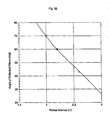
- Fig. 45 shows phases of reflected waves for the mushroom elements having length from L1 to L11 in the tapered mushroom structure shown in Fig. 44 .
- the phase is -90° when the length is L11 (20.70 mm), whereas, the phase is 90° when the length is L1 (17.70 mm).
- phase In order to control a phase of a reflected wave and direct the reflected wave to a desired direction, it is desirable that the phase can be changed freely from -180° (- ⁇ radians) to 180° ( ⁇ radians).
- phase of reflected waves are approximately determined based on a gap interval between patches being adjacent in a Y axis direction of Fig. 44 .
- the patch interval can be made small when the length of the patch in the Y axis direction is increased.
- the tapered mushroom structure shown in Fig. 44 is sized 161 mm in the Y axis direction and 187 mm in the X axis direction, and any of them is 1.5 ⁇ or less, which is not sufficiently large as a reflector plate for reflecting radio waves.
- Design values in Fig. 44 and Table 1 are those when the reflection angle ⁇ is approximately 22°.
- ⁇ x is made smaller in accordance with (the expression #1A), and the entire size of the reflector plate is also made smaller.
- the present invention has been made in light of the above problems, and aims to provide a radio communication system, a periodic structure reflector plate and a tapered mushroom structure which can: (1) configure a large sized reflector plate having a function to control a direction in which reflected waves travel so that the reflected waves travel in a desired direction; (2) control the desired direction by changing a period of the reflector plate; and (3) control a direction in which the reflected waves travel, in a two-dimensional manner (i.e. in the X-Y directions).
- a first aspect of the present invention is summarized as a radio communication system configured to secondarily-radiate, to a desired area by reflection, primarily-radiated radio waves from a transmitter apparatus, by using a reflector plate for controlling phases of reflected waves, wherein a reflecting property of the reflector plate is set so that the reflector plate reflects the primarily-radiated radio waves as plane waves of equal phase directed to a direction different from a reflection angle in the case of specular reflection.
- the reflector plate can be formed by a frequency selective reflector plate; and the reflecting property of the reflector plate can be set so that the reflector plate reflects only radio waves of one or a plurality of predetermined frequency bands, among the primarily-radiated radio waves, as the plane waves of the equal phase directed to the direction different from the reflection angle in the case of the specular reflection.
- a second aspect of the present invention is summarized as a periodic structure reflector plate including a structure in which structures each for controlling a reflection angle by controlling a phase difference of reflected waves are periodically arranged.
- a third aspect of the present invention is summarized as a tapered mushroom structure formed of mushroom elements including a dielectric substrate having a metal ground plate as a bottom face, strip-shaped patches formed on an upper surface of the dielectric substrate, and short pins short-circuiting the metal ground plate and the patches, wherein n mushroom elements are arranged at predetermined intervals of ⁇ X i in an X axis direction, and m mushroom elements are arranged at predetermined intervals of ⁇ Y j in a Y axis direction; the length LY ij of each mushroom element in the Y axis direction is changed by being inclined along the X axis direction, the length LX ij of each mushroom element in the X axis direction is changed by being inclined along the Y axis direction, or not only the length LY ij of each mushroom element in the Y axis direction is changed by being inclined along the X axis direction, but also the length LX ij of each mushroom element in the X axis direction is changed
- a forth of the present invention is summarized as a tapered mushroom structure formed of mushroom elements including a dielectric substrate having a metal ground plate as a bottom face, strip-shaped patches formed on an upper surface of the dielectric substrate, and short pins short-circuiting the metal ground plate and the patches, wherein n mushroom elements are arranged at predetermined intervals of ⁇ X i in an X axis direction, and m mushroom elements are arranged at predetermined intervals of ⁇ Y j in a Y axis direction; the length LY ij of each mushroom element in the Y axis direction is changed by being inclined along the Y axis direction, the length LX ij of each mushroom element in the X axis direction is changed by being inclined along the X axis direction, or not only the length LY ij of each mushroom element in the Y axis direction is changed by being inclined along the Y axis direction but also the length LX ij of each mushroom element in the X axis direction is changed by being
- the length LY ij of each mushroom element in the Y axis direction can be changed by being inclined along the Y axis direction and the X axis direction.
- the length LX ij of each mushroom element in the X axis direction can be changed by being inclined along the Y axis direction and the X axis direction.
- each mushroom element can be arranged so that there is no lag in a phase difference between the k th mushroom element and the k-l th mushroom element with respect to any k.
- each mushroom element can be arranged so that there is no phase difference between the p th period and the p-l th period with respect to any P.
- exp(j)", using a free space impedance ⁇ and a surface impedance Z s ; and when the surface impedance Z s is determined by an expression #4 "Z s j ⁇ L/(1- ⁇ 2 LC)", using inductance L and capacitance C which are determined by the tapered mushroom structure, the i mushroom elements can be arranged in the X axis direction, the phases of the reflection coefficient, which are approximately determined from the inductance L and the capacitance C, can be at
- the tapered mushroom structure according to any one of the third aspect and the forth aspect can be configured.
- a direction in which the reflected wave propagates can be varied by changing a period T of each block depending on the radio wave propagation environment in the surroundings where the periodic structure reflector plate is installed.
- the periodic structure reflector plate according to the second aspect can be used as the reflector plate.
- the transmitter apparatus can be any one of a radio base station and a mobile station.
- a tapered mushroom structure of a first embodiment of the present invention will be described with reference to Fig. 1 .
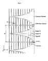
- Fig. 1 shows the tapered mushroom structure according to this embodiment, in which 11 mushroom elements 2 are arranged at predetermined intervals ⁇ X i in an X axis direction (vertical direction) and 7 mushroom elements 2 are arranged at predetermined intervals of ⁇ Y j in a Y axis direction (horizontal direction).
- the mushroom element 2 includes a dielectric substrate 1 having a metal ground plate as a bottom face, strip-shaped patches 2A configured on a top surface of the dielectric substrate 1, and a short pin 3 for short-circuiting the metal ground plate and the patches 2A.
- each mushroom element 2 in the Y axis direction is configured to change as it inclines along the X axis direction.
- taper inclination
- a phase of a reflected wave can be changed.
- the left-handed transmission line model of (1) is used.
- a method of designing each mushroom element of this embodiment will be described hereinafter.
- Fig. 2 and Fig. 3 show structural parameters of the tapered mushroom structure according to this embodiment.
- Fig. 2 consider interval of the mushroom elements in the X axis direction ⁇ x.
- a phase of a reflection coefficient when a plane wave enters from a front direction of the reflector plate (positive direction of a Z axis in Fig. 1 to Fig. 3 ) to the reflector plate configured in the tapered mushroom structure is ⁇
- a phase difference of the reflection coefficient to an adjacent mushroom element is ⁇ .
- C ⁇ o ⁇ 1 + ⁇ r ⁇ W x ⁇ arccosh ⁇ ⁇ y ⁇ y - W y
- the tapered mushroom structure according to this embodiment can be increased in the horizontal direction.
- the tapered mushroom structure cannot be increased in the vertical direction, because the pitch is already determined and there is a limit in producing mushroom elements shorter or longer than the current ones.
- Fig. 2 and Fig. 3 show respective parameters when the phases are configured to change at equal intervals between - ⁇ /2 and ⁇ /2 by using approximate expressions of the expression #5 to the expression #9, and Table 2 shows values of such parameters.
- the interval of the mushroom elements in the X axis direction is expressed by Ax
- the interval of the mushroom elements in the Y axis direction is expressed by ⁇ y
- spacing (gap) of the n th mushroom element in the Y axis direction is expressed by G ygap (n).
- Wx is a width of the mushroom element in the X axis direction
- gx is a gap between the mushroom elements in the X axis direction
- W ynj is a width of the n th mushroom element in the Y axis direction
- Y length (n) is a length of the n th mushroom element in the Y direction.
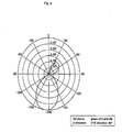
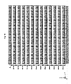
- Fig. 4 shows analysis result of a far scattered field of the tapered mushroom structure according to this embodiment.
- Fig. 4 shows a result when plane waves are given to the reflector plate in a positive direction of the Z axis.
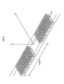
- tapered mushroom structure may also be configured to determine the length of each mushroom element, so that the phases of the reflection coefficients when radio waves are reflected at each mushroom element are parallel to a straight line arbitrarily set on the XY plane (see Fig. 43 ).
- a tapered mushroom structure according to a second embodiment of the present invention will be described hereinafter.
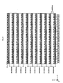
- a collection of 1 x 11 mushroom elements (see Fig. 6 ), which are tapered based on the method of designing shown in Fig. 2 and Fig. 3 , is defined as one block. These blocks are periodically arranged in the vertical direction (X axis direction) and the horizontal direction (Y axis direction).
- a period in the vertical direction is 29.0324 mm.
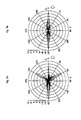
- Fig. 7A and Fig. 7B show properties of the far scattered field of the tapered mushroom structure according to this embodiment.
- Fig. 7A shows a result of analysis by a finite element method of the far scattered field of the tapered mushroom structure as shown in Fig. 5
- Fig. 7B shows a result of analysis by the finite element method of the far scattered field of a metal flat plate having the same size as that in Fig. 7A .
- radio waves are radiated to a direction of about 58°, which is 10° less than a designed value, at a level higher than those in the direction 0° of the specular reflection, while in the case of the metal flat plate, reflected waves are only directed to a direction of the specular reflection.
- a tapered mushroom structure according to the third embodiment of the present invention will be described hereinafter.
- a tapered mushroom structure according to a fourth embodiment of the present invention will be described hereinafter.
- Fig. 10 is a general view of the tapered mushroom structure in which the mushroom elements are arranged with the period of 36 mm at 8.8 GHz.
- a periodic structure reflector plate (tapered mushroom structure) of 450 mm x 450 mm is created by arranging 13 blocks of the mushroom elements in the X axis direction and 45 blocks in the Y axis direction, each block being formed of 13 mushroom elements arranged in the X axis direction.
- Fig. 11 shows a structure of such a block
- Fig. 12 shows a structure of the mushroom element forming each block.
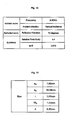
- design conditions are as shown in Fig. 13 .
- pitch a x in the X axis direction is 1.80 mm
- pitch a y in the Y axis direction is 10 mm
- width W x of the mushroom element in the X axis direction is 1.20 mm
- a diameter d of a via is 0.30 mm.
- a value of a x is a value of ⁇ x in the expression #5 when the phase difference ⁇ of the reflection coefficient is ⁇ /10 and the angle ⁇ indicative of the traveling direction of the desired reflected wave is 70°.
- Fig. 15 shows a result of determination of a value for the phase of the reflection coefficient to W y when a value of length W y of the mushroom elements in the Y axis direction is changed after the structural parameters are set, as shown in Fig. 14 .
- a value of W y for which a phase difference changes by ⁇ /10°, may be determined from Fig. 15 .
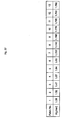
- Fig. 16 shows values of respective W y when the value of W y of the tapered mushroom structure is determined and values of gaps of adjacent mushroom elements.
- Fig. 16 shows values of the structural parameters for 3 blocks, for descriptive purposes.
- a tapered mushroom structure according to a fifth embodiment of the present invention will be described hereinafter.
- the tapered mushroom structure according to the present invention has an effect of directing beams to a desired direction, even when the number of the mushroom elements is increased or decreased.
- a direction in which a taper is given may be a positive direction or a negative direction.
- Fig. 18 shows lengths of one block forming the tapered mushroom structure of this embodiment, that is to say, lengths of the 15 mushroom elements of the tapered mushroom structure.
- Fig. 20 shows a far scattered field then. As shown in Fig. 20 , it can be seen that the reflected waves are directed to a desired direction, which is a direction of -70°.
- the beams (beams of -70° in Fig. 20 ) in the 70° direction, which is the desired direction, are at 9.37 dB in the case of the 15 mushroom elements, the level of which is higher than 9.12 dB in the case of the 13 mushroom elements.
- the level of the direction of the specular reflection is 3.66 dB in the case of the 13 mushroom elements, and -0.16 dB in the case of the 15 mushroom elements.
- the case of the 15 mushroom elements is more effective to bend beams of reflected waves.
- a tapered mushroom structure according to the present invention may change size of a reflector plate by changing the number of blocks to be arranged in a period direction.
- the number of mushroom elements in one block shall be 13, which is the same as the case of the fourth embodiment, and a reflector plate of 300 mm 2 is formed by arranging 30 blocks in the Y axis direction and 11 blocks in the X axis direction with the period being 36 mm.
- Fig. 21 shows a far scattered field then. As shown in Fig. 21 , although the level of the maximum radiation direction is 4.15 dB, which is smaller than 9.12 dB in the case of 450 mm 2 , the reflected waves bend in the direction of 70°.
- FIG. 22 shows one block forming the tapered mushroom structure according to this embodiment
- Fig. 23 shows structural parameters to be used in the tapered mushroom structure according to this embodiment.
- This embodiment shows an example of when pitch a x of the mushroom elements in the X axis direction and pitch a y of the mushroom elements in the Y axis direction are in almost the same size as 1.8 mm and the period T is 36 mm, in the tapered mushroom structure according to the present invention.
- Fig. 25 shows the structural parameters.
- Fig. 26 shows phases of reflection coefficients for the length of W y then.
- Fig. 27 shows values of W y selected so that a phase difference for every pitch a x in the X axis direction will be ⁇ /10.
- Fig. 28 and Fig. 29 show details of structural parameters to be used in the tapered mushroom structure according to this embodiment and their values.
- Fig. 30 shows a structure in which the period T is 2 ⁇ , 2 blocks are arranged in the X axis direction, and 7 blocks are arranged in the Y axis direction, and Fig. 31 shows a far scattered field when a reflector plate of 450 mm 2 is created by arranging 250 blocks in the Y axis direction and 12 blocks in the Y axis direction.
- a tapered mushroom structure according to the eighth embodiment will be described.
- Fig. 32 shows the value of the period T of the block in the tapered mushroom structure according to the fourth embodiment shown in Fig. 11 , and values of the reflected waves in the radiation direction to the period T when the mushroom elements are arranged by changing the value of the period T of the block in the tapered mushroom structure according to the second embodiment shown in Fig. 6 .
- the direction of the reflected waves can be changed 40° or more, by changing T from 2 ⁇ to 3 ⁇ .
- Fig. 33 is a view for describing how the tapered mushroom structure and the phases are when the period T is changed.
- the mushroom element #1 of the block 1 and the mushroom element #1 of the block 2 are in the same phase and both are spaced by the interval of the period T.
- a tapered mushroom structure according to a ninth embodiment of the present invention will be described hereinafter.
- Fig. 34 shows a radio communication system according to a ninth embodiment of the present invention which enables radio waves to reach by using the periodic structure reflector plate (tapered mushroom structure) of the present invention, in the environment such that radio waves cannot easily reach a direction in which a mobile station j is located even if a reflector plate is installed in the conventional specular reflection.
- a reflection angle can be changed to a desired direction by sliding a period T of a reflector plate, as shown in Fig. 35 , when there arises a need to change the initially assumed reflection angle ⁇ r1 to ⁇ r2, due to environmental changes.
- a method of sliding may be manual or mechanically driven.
- a tapered mushroom structure according to a tenth embodiment of the present invention will be described hereinafter.
- Fig. 42 shows an example of a configuration in which when an electric field of incoming incident wave is directed to direction Y, length LY ij of each mushroom element in the Y axis direction is changed by being inclined along the Y axis direction. Now, " ⁇ sin -1 ("( ⁇ /(2 ⁇ y))". Then, on the YZ plane, an angle indicative of a desired traveling direction of the reflected wave can be changed by ⁇ , with respect to the specular reflection.
- a tapered mushroom structure according to an eleventh embodiment of the present invention will be described hereinafter.
- a configuration may be such that when an electric field of incoming incident wave is directed to direction Y, length LY ij of each mushroom element in the Y axis direction is changed by not only inclining it along the X axis direction, but also inclining it along the Y axis direction.
- a tapered mushroom structure according to a twelfth embodiment of the present invention will be described hereinafter.
- a tapered mushroom structure according to a thirteenth embodiment of the present invention will be described hereinafter.
- a configuration may be such that not only length LY ij of each mushroom element in a Y axis direction is changed by being inclined along an X axis direction, but also length LX ij of each mushroom element in the X axis direction is changed by being inclined along the Y axis direction.
- a tapered mushroom structure according to a fourteenth embodiment of the present invention will be described hereinafter.
- a configuration may be such that not only length LY ij of each mushroom element in Y axis direction is changed by being inclined along a Y axis direction and an X axis direction, but also length LX ij of each mushroom element in the X axis direction is changed by being inclined along the X axis direction and the Y axis direction.
- Fig. 36 and Fig. 37 show a mushroom structure in which mushroom elements 2 without a via hole 3, which are formed of a dielectric substrate 1 and patches 2A are arranged.
- length of the patches 2A is determined by a phase difference.
- Fig. 38 shows a contour figure of phrases of reflection coefficients in such a tapered mushroom structure. As shown in Fig. 38 , it can be seen that phase differences are clearly shown depending on length of the patch 2A in the tapered mushroom structure.
- Fig. 39 shows a tapered mushroom structure only formed of strip-shaped metals.
- Fig. 40 shows a tapered mushroom structure only formed of strip-shaped slots.
- the present invention can provide a radio communication system, a periodic structure reflector plate, and a tapered mushroom structure, capable of: configuring the size of a reflector plate having a function to control a direction in which reflected waves travel so that the reflected waves travel in a desired direction; easily carrying out control; and operating beams in a two-dimensional manner.
Landscapes
- Physics & Mathematics (AREA)
- Optics & Photonics (AREA)
- Engineering & Computer Science (AREA)
- Computer Networks & Wireless Communication (AREA)
- Aerials With Secondary Devices (AREA)
- Radio Transmission System (AREA)
Abstract
Description
- The present invention relates to a radio communication system, a periodic structure reflector plate, and a tapered mushroom structure. For example, the present invention relates to a radio communication system including the following functions.
- (1) A function in which such a reflecting property is set in a reflector plate for controlling a phase of a reflected wave (reflection phase) that primarily-radiated radio waves from a transmitter apparatus are reflected as plane waves of an equal phase directed to a desired area in a direction different from a regular reflection (specifically, a specular reflection).
- (2) A function to configure a reflector plate which is large enough for a wavelength, through periodic arrangement of structures controlling a reflection angle by controlling a phase difference of reflected waves.
- In recent years, research on meta-material has been active, and, as described in the non-Patent Document 1 (see "High-impedance Surface with Nonidentical Lattices", K. Chang, J. Ahn and Y. J. Yoon, iWAT2008, p315, pp474 to 477), there is discussed a technique for controlling a radiation direction by adding a taper (inclination) in a mushroom structure to give reflected waves a phase difference.
-
Fig. 44 shows a tapered mushroom structure shown in Non-PatentDocument 1. As shown inFig. 44 , such a tapered mushroom structure is formed of mushroom elements having 11 patches of L1 to L11 which have different lengths. Table 1 shows detailed dimensions of the mushroom structure shown inFig. 44 .Table 1 Parameter Value Parameter Value L1 17.70mm L2 18.27mm L3 18.66mm L4 19.00mm L5 19.28mm L6 19.53mm L7 19.77mm L8 20.00mm L9 20.23mm L10 20.47mm L11 20.70mm Width of Unit Cell Δx 17mm Length of Unit Cell Δy 23mm Phase Difference between Adjacent Cells Δϕ π/10 - As shown in
Fig. 45 , resonance frequencies of the periodically arranged mushroom structures as shown inFig. 44 vary by changing a patch size. -
Fig. 45 shows phases of reflected waves for the mushroom elements having length from L1 to L11 in the tapered mushroom structure shown inFig. 44 . - As shown in
Fig. 45 , at 2.4 GHz, the phase is -90° when the length is L11 (20.70 mm), whereas, the phase is 90° when the length is L1 (17.70 mm). - In order to control a phase of a reflected wave and direct the reflected wave to a desired direction, it is desirable that the phase can be changed freely from -180° (-π radians) to 180° (π radians).
- When a case of a conventional tapered mushroom structure is considered, according to the transmission line theory, phases of reflected waves are approximately determined based on a gap interval between patches being adjacent in a Y axis direction of
Fig. 44 . However, when length of the patches in the Y axis direction is too small compared with the patch interval, it is difficult to apply the transmission line theory and the phases of the reflected waves no longer changes. In addition, the patch interval can be made small when the length of the patch in the Y axis direction is increased. However, there is a limit in manufacturing if the length is made too small. - For these reasons, the conventional tapered mushroom structure cannot ensure a sufficient dynamic range.
- In addition, the tapered mushroom structure shown in
Fig. 44 is sized 161 mm in the Y axis direction and 187 mm in the X axis direction, and any of them is 1.5λ or less, which is not sufficiently large as a reflector plate for reflecting radio waves. - Furthermore, in control of a phase difference using the tapered mushroom structure shown in
Fig. 44 , a reflection angle θ and a periodic interval Δx (pitch) in the X axis direction have a relationship approximated by anexpression # 1 "θ = sin-1((λ·ΔΦ)/(2π·Δx))". - Design values in
Fig. 44 and Table 1 are those when the reflection angle θ is approximately 22°. However, there has been a disadvantage that when the reflection angle θ is further increased, Δx is made smaller in accordance with (the expression #1A), and the entire size of the reflector plate is also made smaller. - In addition, in the conventional tapered mushroom structure, a method of controlling beam in an orthogonal direction (direction Y, in this case) has not been considered at all.
- As described above, in the conventional tapered mushroom structure, there has been a disadvantage that a large reflector plate cannot be constructed because there is a limit in a phase difference to be obtained by changing dimensions of respective mushroom elements which form a periodic structure.
- Hence, the present invention has been made in light of the above problems, and aims to provide a radio communication system, a periodic structure reflector plate and a tapered mushroom structure which can: (1) configure a large sized reflector plate having a function to control a direction in which reflected waves travel so that the reflected waves travel in a desired direction; (2) control the desired direction by changing a period of the reflector plate; and (3) control a direction in which the reflected waves travel, in a two-dimensional manner (i.e. in the X-Y directions).
- A first aspect of the present invention is summarized as a radio communication system configured to secondarily-radiate, to a desired area by reflection, primarily-radiated radio waves from a transmitter apparatus, by using a reflector plate for controlling phases of reflected waves, wherein a reflecting property of the reflector plate is set so that the reflector plate reflects the primarily-radiated radio waves as plane waves of equal phase directed to a direction different from a reflection angle in the case of specular reflection.
- In the first aspect, the reflector plate can be formed by a frequency selective reflector plate; and the reflecting property of the reflector plate can be set so that the reflector plate reflects only radio waves of one or a plurality of predetermined frequency bands, among the primarily-radiated radio waves, as the plane waves of the equal phase directed to the direction different from the reflection angle in the case of the specular reflection.
- A second aspect of the present invention is summarized as a periodic structure reflector plate including a structure in which structures each for controlling a reflection angle by controlling a phase difference of reflected waves are periodically arranged.
- In the second aspect, in n reflector plate constituent pieces rk (1≤k≤n) arranged at intervals of ΔSk, when a phase of reflected wave in each reflector plate constituent piece rk is Φk, a phase difference (Φk+1 - Φk) between each reflector plate constituent piece rk and an adjacent reflector plate constituent piece rk+1 is ΔΦk, and wavelength of the reflected wave is λ, a plurality of blocks can be provided for every period T (T≥RL), each of the blocks being formed of the n reflector plate constituent pieces rk that are arranged to satisfy an
expression # 1 "α = sin-1(λ·ΔΦk/2π·ΔSk)" for an angle α indicative of a traveling direction of desired reflected wave, each of the blocks having a length RL specified by:
- In the second aspect, the period T can be a value for which "T = λ/sinα" is true.
- A third aspect of the present invention is summarized as a tapered mushroom structure formed of mushroom elements including a dielectric substrate having a metal ground plate as a bottom face, strip-shaped patches formed on an upper surface of the dielectric substrate, and short pins short-circuiting the metal ground plate and the patches, wherein n mushroom elements are arranged at predetermined intervals of ΔXi in an X axis direction, and m mushroom elements are arranged at predetermined intervals of ΔYj in a Y axis direction; the length LYij of each mushroom element in the Y axis direction is changed by being inclined along the X axis direction, the length LXij of each mushroom element in the X axis direction is changed by being inclined along the Y axis direction, or not only the length LYij of each mushroom element in the Y axis direction is changed by being inclined along the X axis direction, but also the length LXij of each mushroom element in the X axis direction is changed by being inclined along the Y axis direction; and the length of each mushroom element is determined so that a phase of a reflection coefficient when radio wave is reflected in each mushroom element is parallel to a straight line set arbitrarily on an XY plane.
- A forth of the present invention is summarized as a tapered mushroom structure formed of mushroom elements including a dielectric substrate having a metal ground plate as a bottom face, strip-shaped patches formed on an upper surface of the dielectric substrate, and short pins short-circuiting the metal ground plate and the patches, wherein n mushroom elements are arranged at predetermined intervals of ΔXi in an X axis direction, and m mushroom elements are arranged at predetermined intervals of ΔYj in a Y axis direction; the length LYij of each mushroom element in the Y axis direction is changed by being inclined along the Y axis direction, the length LXij of each mushroom element in the X axis direction is changed by being inclined along the X axis direction, or not only the length LYij of each mushroom element in the Y axis direction is changed by being inclined along the Y axis direction but also the length LXij of each mushroom element in the X axis direction is changed by being inclined along the X axis direction; and the length of each mushroom element is determined so that a phase of a reflection coefficient when radio waves are reflected at each mushroom element is parallel to a straight line arbitrarily set on an XY plane.
- In the third aspect and the forth aspect, the length LYij of each mushroom element in the Y axis direction can be changed by being inclined along the Y axis direction and the X axis direction.
- In the third aspect and the forth aspect, the length LXij of each mushroom element in the X axis direction can be changed by being inclined along the Y axis direction and the X axis direction.
- In the third aspect and the forth aspect, if the m or n mushroom elements cannot be arranged due to restrictions on the length LXij in the X axis direction and the length LYij in the Y axis direction which are determined by the predetermined intervals ΔXi and ΔYj, blocks in which the mushroom elements are arranged at the predetermined intervals ΔXi in the X axis direction and at the predetermined intervals ΔYj in the Y axis direction can be periodically and repeatedly arranged.
- In the third aspect and the forth aspect, each mushroom element can be arranged so that there is no lag in a phase difference between the kth mushroom element and the k-lth mushroom element with respect to any k.
- In the third aspect and the forth aspect, each mushroom element can be arranged so that there is no phase difference between the pth period and the p-lth period with respect to any P.
- In the third aspect and the forth aspect, in the mushroom elements to be arranged at intervals of Δx, when a phase difference of a reflection coefficient at each mushroom element is ΔΦ and wavelength of a reflected wave is λ, an angle α indicative of a desired traveling direction of a reflected wave can be determined by an
expression # 2 "α = sin-1(λ·ΔΦ/2π·ΔX)"; the reflection coefficient r can be determined by anexpression # 3 "Γ = (Zs-η)/(Zs+η) = |Γ|exp(j)", using a free space impedance η and a surface impedance Zs; and when the surface impedance Zs is determined by anexpression # 4 "Zs = jωL/(1-ω2LC)", using inductance L and capacitance C which are determined by the tapered mushroom structure, the i mushroom elements can be arranged in the X axis direction, the phases of the reflection coefficient, which are approximately determined from the inductance L and the capacitance C, can be at regular intervals for the every interval Δx so that the phase difference ΔΦ will be equal, and blocks in which the i mushroom elements are arranged in the X axis direction can be arranged at intervals of a predetermined period T. - In the second aspect, the tapered mushroom structure according to any one of the third aspect and the forth aspect can be configured.
- In the second aspect, a direction in which the reflected wave propagates can be varied by changing a period T of each block depending on the radio wave propagation environment in the surroundings where the periodic structure reflector plate is installed.
- In the first aspect, the periodic structure reflector plate according to the second aspect can be used as the reflector plate.
- In the first aspect, the transmitter apparatus can be any one of a radio base station and a mobile station.
-
-
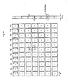
Fig. 1 is a view showing a tapered mushroom structure according to a first embodiment of the present invention. -
Fig. 2 is a view showing structural parameters of the tapered mushroom structure according to the first embodiment of the present invention. -
Fig. 3 is a view showing structural parameters of the tapered mushroom structure according to the first embodiment of the present invention. -
Fig. 4 is a graph showing a far scattered field in the tapered mushroom structure according to the first embodiment of the present invention. -
Fig. 5 is a view showing a tapered mushroom structure according to a second embodiment of the present invention. -
Fig. 6 is a view showing one block forming the tapered mushroom structure according to the second embodiment of the present invention. -
Figs. 7A and 7B are graphs showing far scattered fields in the tapered mushroom structure according to the second embodiment of the present invention. -
Fig. 8 is a view showing a tapered mushroom structure according to a third embodiment of the present invention. -
Fig. 9 is a graph showing a far scattered field in the tapered mushroom structure according to the third embodiment of the present invention. -
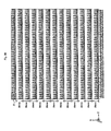
Fig. 10 is a view showing a tapered mushroom structure according to a fourth embodiment of the present invention. -
Fig. 11 is a view showing one block forming the tapered mushroom structure according to the fourth embodiment of the present invention. -
Fig. 12 is a view showing structural parameters of the tapered mushroom structure according to the fourth embodiment of the present invention. -
Fig. 13 is a view showing design conditions of the tapered mushroom structure according to the fourth embodiment of the present invention. -
Fig. 14 is a view showing values of the structural parameters of the tapered mushroom structure according to the fourth embodiment of the present invention. -
Fig. 15 is a graph showing values of phases of reflection coefficients to Wy when length Wy of the mushroom element in the Y axis direction is changed, in the tapered mushroom structure according to the fourth embodiment of the present invention. -
Fig. 16 is a view showing values of each Wy when values of Wy are determined, and values of gaps between adjacent mushroom elements, in the tapered mushroom structure according to the fourth embodiment of the present invention. -
Fig. 17 is a graph showing a far scattered field in the tapered mushroom structure according to the fourth embodiment of the present invention. -
Fig. 18 is a view showing the length of a tapered mushroom structure for one block in a tapered mushroom structure according to a fifth embodiment of the present invention. -
Fig. 19 is a view showing one block forming the tapered mushroom structure according to the fifth embodiment of the present invention. -
Fig. 20 is a graph showing a far scattered field in the tapered mushroom structure according to the fifth embodiment of the present invention. -
Fig. 21 is a graph showing a far scattered field in a tapered mushroom structure according to a sixth embodiment of the present invention. -
Fig. 22 is a view showing one block forming a tapered mushroom structure according to a seventh embodiment of the present invention. -
Fig. 23 is a view showing structural parameters of the tapered mushroom structure according to the seventh embodiment of the present invention. -
Fig. 24 is a view showing design conditions of the tapered mushroom structure according to the seventh embodiment of the present invention. -
Fig. 25 is a view showing values of the structural parameters of the tapered mushroom structure of the seventh embodiment of the present invention. -
Fig. 26 is a graph showing values of phases of the reflection coefficients to Wy when length Wy of the mushroom element in the Y axis direction is changed, in the tapered mushroom structure according to the seventh embodiment of the present invention. -
Fig. 27 is a view showing values of one block forming the tapered mushroom structure according to the seventh embodiment of the present invention. -
Fig. 28 is a view showing structural parameters to be used in the tapered mushroom structure according to the seventh embodiment of the present invention. -
Fig. 29 is a view showing details of the structural parameters to be used in the tapered mushroom structure according to the seventh embodiment of the present invention. -
Fig. 30 is a view showing one block forming the tapered mushroom structure according to the seventh embodiment of the present invention. -
Fig. 31 is a graph showing a far scattered field in the tapered mushroom structure according to the seventh embodiment of the present invention. -
Fig. 32 is a graph showing values of radiation direction of reflected waves to a period T when the value of the period T of the block in the tapered mushroom structure is changed and the mushroom elements are arranged, in the tapered mushroom structure according to an eighth embodiment of the present invention. -
Fig. 33 is a view for describing how the tapered mushroom structure and the phases are when the period T is changed, in the tapered mushroom structure according to the eighth embodiment of the present invention. -
Fig. 34 is a view for describing a radio communication system according to a ninth embodiment of the present invention. -
Fig. 35 is a view for describing the radio communication system according to the ninth embodiment of the present invention. -
Fig. 36 is a view showing a tapered mushroom structure according to Modification Example 1 of the present invention. -
Fig. 37 is a view showing one block forming the tapered mushroom structure according to Modification Example 1 of the present invention. -
Fig. 38 is a contour figure of phases of reflection coefficients in the tapered mushroom structure according to Modification Example 1 of the present invention. -
Fig. 39 is a view showing the tapered mushroom structure according to Modification Example 2 of the present invention. -
Fig. 40 is a view showing the tapered mushroom structure according to Modification Example 2 of the present invention. -
Fig. 41 is a view showing one example of a tapered mushroom structure according to an eleventh embodiment of the present invention. -
Fig. 42 is a view showing one example of a tapered mushroom structure according to a tenth embodiment of the present invention. -
Fig. 43 is a contour figure of phases of reflection coefficients in the tapered mushroom structure according to the first embodiment of the present invention. -
Fig. 44 is a view showing a conventional tapered mushroom structure. -
Fig. 45 is a graph showing values of phases of reflection coefficients when values of length of mushroom elements in Y axis direction are changed in the conventional tapered mushroom structure. - In the following, embodiments of the present invention will be described in detail with reference to the drawings.
- A tapered mushroom structure of a first embodiment of the present invention will be described with reference to
Fig. 1 . -
Fig. 1 shows the tapered mushroom structure according to this embodiment, in which 11mushroom elements 2 are arranged at predetermined intervals ΔXi in an X axis direction (vertical direction) and 7mushroom elements 2 are arranged at predetermined intervals of ΔYj in a Y axis direction (horizontal direction). - As shown in
Fig. 1 , themushroom element 2 includes adielectric substrate 1 having a metal ground plate as a bottom face, strip-shaped patches 2A configured on a top surface of thedielectric substrate 1, and ashort pin 3 for short-circuiting the metal ground plate and the patches 2A. - In the example of
Fig. 1 , length of eachmushroom element 2 in the Y axis direction is configured to change as it inclines along the X axis direction. In other words, in the tapered mushroom structure according to this embodiment, taper (inclination) is given in the vertical direction, and as a result, a phase of a reflected wave can be changed. - The following two methods are known as examples each for a design of the tapered mushroom structure.
- (1) A method of making the design in an approximate manner by using a left-handed transmission line model since the mushroom structure has a structure with inductance L and capacitance C of a usual transmission line model inverted
- (2) A method of aligning a phase of a reflected wave in each mushroom element with a desired direction, similar to a reflect array.
- In this embodiment, the left-handed transmission line model of (1) is used. A method of designing each mushroom element of this embodiment will be described hereinafter.
-
Fig. 2 andFig. 3 show structural parameters of the tapered mushroom structure according to this embodiment. - In
Fig. 2 , consider interval of the mushroom elements in the X axis direction Δx. Here, assume that a phase of a reflection coefficient when a plane wave enters from a front direction of the reflector plate (positive direction of a Z axis inFig. 1 to Fig. 3 ) to the reflector plate configured in the tapered mushroom structure is ϕ, and that a phase difference of the reflection coefficient to an adjacent mushroom element is Δϕ. In this case, an angle (reflection angle) α indicative of a traveling direction of a desired reflected wave can be expressed by anexpression # 5 "α = sin-1((λ·ΔΦ)/(2π·Δx))". - Here, the reflection coefficient Γ can be expressed as an
expression # 6 "Γ = (Zs-η)/(Zs+η) = |Γ|exp(j)" by using a free space impedance η and a surface impedance Zs. - The surface impedance Zs can be expressed as an
expression # 7 "Zs = jωL/(1-ω2LC)" by using the inductance L and the capacitance C which depend on the tapered mushroom structure. - Here, the inductance L is expressed by an
expression # 8 "L = µo·t", when thickness of thedielectric substrate 1 is t and magnetic permeability of the free space is µo. - In addition, the capacitance C is expressed by an
expression # 9.
- The tapered mushroom structure according to this embodiment can be increased in the horizontal direction. However, the tapered mushroom structure cannot be increased in the vertical direction, because the pitch is already determined and there is a limit in producing mushroom elements shorter or longer than the current ones.
-
Fig. 2 andFig. 3 show respective parameters when the phases are configured to change at equal intervals between -π/2 and π/2 by using approximate expressions of theexpression # 5 to theexpression # 9, and Table 2 shows values of such parameters.Table 2 Gap in X direction; gx 0.2mm Gygap(1)-0.299580mm Ylength(1)=9.700420mm Thickness of substrate t 3.2mm Gygap(Z)=0.499814mm Ylength(2)=9.500186mm Relative permittivity or 4.9 Gygap(3)=0.749932mm Ylength(3)=9.250068mm Center frequency 12GHz Gygap(4)=1.058274mm Ylength(4)=8.941726mm Pitch in X direction: Δy 10mm Gygap(5)=1.442206mm Ylength(5)=8.557794mm Desired angleΦ 70° Gygap(6)=1.932170mm Ylength(6)=8.067830mm Phase differences of reflected waves π/10 Gygap(7)=2.579860mm Ylength(7)=7.420140mm Patch width in X direction: Wx 1.1302mm Gygap(8)=3.473434mm Ylength(8)=6.526566mm Wavelength 25mm Gygap(9)=4.760696mm Ylength(9)=5.239304mm Pitch in X direction: Δx 1.33mm Gygap(10)=6.645830mm Ylength(10)=3.354170mm Gygap(11)=9.049691mm Ylength(11)=0.950309mm - In
Fig. 2 , the interval of the mushroom elements in the X axis direction is expressed by Ax, the interval of the mushroom elements in the Y axis direction is expressed by Δy, and spacing (gap) of the nth mushroom element in the Y axis direction is expressed by Gygap (n). - In
Fig. 3 , Wx is a width of the mushroom element in the X axis direction, gx is a gap between the mushroom elements in the X axis direction, Wynj is a width of the nth mushroom element in the Y axis direction, and Ylength(n) is a length of the nth mushroom element in the Y direction. -
Fig. 4 shows analysis result of a far scattered field of the tapered mushroom structure according to this embodiment.Fig. 4 shows a result when plane waves are given to the reflector plate in a positive direction of the Z axis. - As shown in
Fig. 4 , it can be seen from such a result that radio waves are not radiated in a direction of θ = 0°, which is the direction of specular reflection, and bend to the direction inclined 45°. However, in this case, the number of the mushroom elements is 11 x 7, and the phases in the X axis direction only move from -π/2 to π/2. Due to this effect, a designed value of a main beam of a reflected wave is α = 70°, whereas, the main beam of actual reflected wave is different therefrom and has inclination of 45°. - In addition, the tapered mushroom structure according to this embodiment may also be configured to determine the length of each mushroom element, so that the phases of the reflection coefficients when radio waves are reflected at each mushroom element are parallel to a straight line arbitrarily set on the XY plane (see
Fig. 43 ). - A tapered mushroom structure according to a second embodiment of the present invention will be described hereinafter.
- As shown in
Fig. 5 , in the tapered mushroom structure according to this embodiment, a collection of 1 x 11 mushroom elements (seeFig. 6 ), which are tapered based on the method of designing shown inFig. 2 andFig. 3 , is defined as one block. These blocks are periodically arranged in the vertical direction (X axis direction) and the horizontal direction (Y axis direction). - In this embodiment, as shown in
Fig. 5 , a period in the vertical direction is 29.0324 mm.Fig. 7A and Fig. 7B show properties of the far scattered field of the tapered mushroom structure according to this embodiment. -
Fig. 7A shows a result of analysis by a finite element method of the far scattered field of the tapered mushroom structure as shown inFig. 5 , andFig. 7B shows a result of analysis by the finite element method of the far scattered field of a metal flat plate having the same size as that inFig. 7A . - It can be seen that in the case of the tapered mushroom structure according to this embodiment, radio waves are radiated to a direction of about 58°, which is 10° less than a designed value, at a level higher than those in the
direction 0° of the specular reflection, while in the case of the metal flat plate, reflected waves are only directed to a direction of the specular reflection. - A tapered mushroom structure according to the third embodiment of the present invention will be described hereinafter.
- In the tapered mushroom structure according to this embodiment, as shown in
Fig. 8 , a period T of the above-mentioned block is 26.6 mm, and at 12 GHz, "T = λ/sinα" is satisfied when α = 70°. -
Fig. 9 shows a far scattered field of the tapered mushroom structure according to this embodiment. It can be seen that the beam is directed to α = 70°, which is a desired direction of the reflected waves, by making the period "T = λ/sinα", and that level of the beam in the direction of -70°, which existed inFig. 7A , is controlled, while the beam is directed to the 58° direction in the example ofFig. 7A . - A tapered mushroom structure according to a fourth embodiment of the present invention will be described hereinafter.
-
Fig. 10 shows the tapered mushroom structure of the third embodiment of the present invention which is designed as α = 70° at 8.8 GHz.Fig. 10 is a general view of the tapered mushroom structure in which the mushroom elements are arranged with the period of 36 mm at 8.8 GHz. - In
Fig. 10 , a periodic structure reflector plate (tapered mushroom structure) of 450 mm x 450 mm is created by arranging 13 blocks of the mushroom elements in the X axis direction and 45 blocks in the Y axis direction, each block being formed of 13 mushroom elements arranged in the X axis direction. -
Fig. 11 shows a structure of such a block, andFig. 12 shows a structure of the mushroom element forming each block. - In this embodiment, design conditions are as shown in
Fig. 13 . In other words, the frequency is 8.8 GHz and vertically polarized wave is used, a reflection direction of reflected wave is α = 70°, thickness of thedielectric substrate 1 is 3.20 mm, and the relative permittivity of thedielectric substrate 1 is εr = 4.4. - In addition, for structural parameters of the mushroom element shown in
Fig. 12 , as shown inFig. 14 , pitch ax in the X axis direction is 1.80 mm, pitch ay in the Y axis direction is 10 mm, width Wx of the mushroom element in the X axis direction is 1.20 mm, and a diameter d of a via is 0.30 mm. - Here, a value of ax is a value of Δx in the
expression # 5 when the phase difference Δϕ of the reflection coefficient is π/10 and the angle α indicative of the traveling direction of the desired reflected wave is 70°. - In this embodiment,
Fig. 15 shows a result of determination of a value for the phase of the reflection coefficient to Wy when a value of length Wy of the mushroom elements in the Y axis direction is changed after the structural parameters are set, as shown inFig. 14 . - In order to bend beams to a desired direction, a value of Wy, for which a phase difference changes by π/10°, may be determined from
Fig. 15 . -
Fig. 16 shows values of respective Wy when the value of Wy of the tapered mushroom structure is determined and values of gaps of adjacent mushroom elements.Fig. 16 shows values of the structural parameters for 3 blocks, for descriptive purposes. -
Fig. 17 shows a far scattered field of the tapered mushroom structure according to this embodiment. As shown inFig. 17 , with such far scattered field, beams are directed to the direction which is inclined 70°, and the radiation level is higher than the direction of specular reflection θ = 0°. - A tapered mushroom structure according to a fifth embodiment of the present invention will be described hereinafter. The tapered mushroom structure according to the present invention has an effect of directing beams to a desired direction, even when the number of the mushroom elements is increased or decreased. In addition, in the tapered mushroom structure according to this embodiment, a direction in which a taper is given may be a positive direction or a negative direction.
- In this embodiment, there are 15 mushroom elements, obtained by adding short mushroom elements and long mushroom elements to the tapered mushroom structure according to the fourth embodiment, and a direction in which taper is given shall be the opposite side to the tapered mushroom structure according to the fourth embodiment.
-
Fig. 18 shows lengths of one block forming the tapered mushroom structure of this embodiment, that is to say, lengths of the 15 mushroom elements of the tapered mushroom structure. - In this embodiment, in the structure of one block shown in
Fig. 19 ,45 mushroom elements are arranged in the Y axis direction and 13 mushroom elements are arranged in the X axis direction. -
Fig. 20 shows a far scattered field then. As shown inFig. 20 , it can be seen that the reflected waves are directed to a desired direction, which is a direction of -70°. - In addition, when compared with the result of
Fig. 17 in which the reflector plate of the same size is created with the number of the mushroom elements shown in the fourth embodiment of the present invention being 13, the beams (beams of -70° inFig. 20 ) in the 70° direction, which is the desired direction, are at 9.37 dB in the case of the 15 mushroom elements, the level of which is higher than 9.12 dB in the case of the 13 mushroom elements. - In contrast, the level of the direction of the specular reflection is 3.66 dB in the case of the 13 mushroom elements, and -0.16 dB in the case of the 15 mushroom elements. In other words, it can be seen that the case of the 15 mushroom elements is more effective to bend beams of reflected waves.
- A tapered mushroom structure according to the present invention may change size of a reflector plate by changing the number of blocks to be arranged in a period direction.
- In the tapered mushroom structure according to a sixth embodiment of the present invention, the number of mushroom elements in one block shall be 13, which is the same as the case of the fourth embodiment, and a reflector plate of 300 mm2 is formed by arranging 30 blocks in the Y axis direction and 11 blocks in the X axis direction with the period being 36 mm.
-
Fig. 21 shows a far scattered field then. As shown inFig. 21 , although the level of the maximum radiation direction is 4.15 dB, which is smaller than 9.12 dB in the case of 450 mm2, the reflected waves bend in the direction of 70°. - A tapered mushroom structure according to a seventh embodiment of the present invention will be described hereinafter.
Fig. 22 shows one block forming the tapered mushroom structure according to this embodiment, andFig. 23 shows structural parameters to be used in the tapered mushroom structure according to this embodiment. - This embodiment shows an example of when pitch ax of the mushroom elements in the X axis direction and pitch ay of the mushroom elements in the Y axis direction are in almost the same size as 1.8 mm and the period T is 36 mm, in the tapered mushroom structure according to the present invention.
- In this embodiment, the design conditions are as shown in
Fig. 24 , the frequency is 8.8 GHz and vertically polarized waves is used (the coordinates are shown inFig. 23 here), and beams bend in the direction of θ = 70° when they enter. - In addition, it is supposed that the
dielectric substrate 1 has the relative permittivity of 4.4 and thickness of 3.2 mm, and tanδ= 0.018.Fig. 25 shows the structural parameters. -
Fig. 26 shows phases of reflection coefficients for the length of Wy then.Fig. 27 shows values of Wy selected so that a phase difference for every pitch ax in the X axis direction will be π/10. -
Fig. 28 andFig. 29 show details of structural parameters to be used in the tapered mushroom structure according to this embodiment and their values. -
Fig. 30 shows a structure in which the period T is 2π, 2 blocks are arranged in the X axis direction, and 7 blocks are arranged in the Y axis direction, andFig. 31 shows a far scattered field when a reflector plate of 450 mm2 is created by arranging 250 blocks in the Y axis direction and 12 blocks in the Y axis direction. - A tapered mushroom structure according to the eighth embodiment will be described.
-
Fig. 32 shows the value of the period T of the block in the tapered mushroom structure according to the fourth embodiment shown inFig. 11 , and values of the reflected waves in the radiation direction to the period T when the mushroom elements are arranged by changing the value of the period T of the block in the tapered mushroom structure according to the second embodiment shown inFig. 6 . - As shown in
Fig. 32 , it can be seen that the direction of the reflected waves can be changed 40° or more, by changing T from 2π to 3π. -
Fig. 33 is a view for describing how the tapered mushroom structure and the phases are when the period T is changed. - In
Fig. 33 , themushroom element # 1 of theblock 1 and themushroom element # 1 of theblock 2 are in the same phase and both are spaced by the interval of the period T. - This also applies to the
mushroom elements # 2 to #11. In addition, there is a phase difference of π/10 between themushroom element # 1 and themushroom element # 2. This enables the direction of reflected waves to be controlled by changing the period T. - A tapered mushroom structure according to a ninth embodiment of the present invention will be described hereinafter.
-
Fig. 34 shows a radio communication system according to a ninth embodiment of the present invention which enables radio waves to reach by using the periodic structure reflector plate (tapered mushroom structure) of the present invention, in the environment such that radio waves cannot easily reach a direction in which a mobile station j is located even if a reflector plate is installed in the conventional specular reflection. - In the radio communication system according to this embodiment, a reflection angle can be changed to a desired direction by sliding a period T of a reflector plate, as shown in
Fig. 35 , when there arises a need to change the initially assumed reflection angle θr1 to θr2, due to environmental changes. A method of sliding may be manual or mechanically driven. - A tapered mushroom structure according to a tenth embodiment of the present invention will be described hereinafter.
-
Fig. 42 shows an example of a configuration in which when an electric field of incoming incident wave is directed to direction Y, length LYij of each mushroom element in the Y axis direction is changed by being inclined along the Y axis direction. Now, "α sin-1("(λ·ΔΦ/(2π·Δy))". Then, on the YZ plane, an angle indicative of a desired traveling direction of the reflected wave can be changed by α, with respect to the specular reflection. - A tapered mushroom structure according to an eleventh embodiment of the present invention will be described hereinafter.
- In
Fig. 41 , a configuration may be such that when an electric field of incoming incident wave is directed to direction Y, length LYij of each mushroom element in the Y axis direction is changed by not only inclining it along the X axis direction, but also inclining it along the Y axis direction. - A tapered mushroom structure according to a twelfth embodiment of the present invention will be described hereinafter.
- If an electric field of incoming incident wave is directed to X direction, length LXij of each mushroom element in the X direction may be configured to be changed by being inclined along the Y axis direction, and "α = sin-1((λ·ΔΦ)/(2π·Δy))" may be set.
- A tapered mushroom structure according to a thirteenth embodiment of the present invention will be described hereinafter.
- In such a tapered mushroom structure, a configuration may be such that not only length LYij of each mushroom element in a Y axis direction is changed by being inclined along an X axis direction, but also length LXij of each mushroom element in the X axis direction is changed by being inclined along the Y axis direction.
- A tapered mushroom structure according to a fourteenth embodiment of the present invention will be described hereinafter.
- In such a tapered mushroom structure, a configuration may be such that not only length LYij of each mushroom element in Y axis direction is changed by being inclined along a Y axis direction and an X axis direction, but also length LXij of each mushroom element in the X axis direction is changed by being inclined along the X axis direction and the Y axis direction.
-
Fig. 36 andFig. 37 show a mushroom structure in whichmushroom elements 2 without a viahole 3, which are formed of adielectric substrate 1 and patches 2A are arranged. Here, length of the patches 2A is determined by a phase difference. -
Fig. 38 shows a contour figure of phrases of reflection coefficients in such a tapered mushroom structure. As shown inFig. 38 , it can be seen that phase differences are clearly shown depending on length of the patch 2A in the tapered mushroom structure. - In addition,
Fig. 39 shows a tapered mushroom structure only formed of strip-shaped metals. - Furthermore,
Fig. 40 shows a tapered mushroom structure only formed of strip-shaped slots. - As described above, the present invention can provide a radio communication system, a periodic structure reflector plate, and a tapered mushroom structure, capable of: configuring the size of a reflector plate having a function to control a direction in which reflected waves travel so that the reflected waves travel in a desired direction; easily carrying out control; and operating beams in a two-dimensional manner.
- So far the present invention has been described in detail using the embodiments described above. However, it is apparent to those skilled in the art that the present invention should not be limited to the embodiments described herein. The present invention can be carried out as a corrected or modified aspect without departing from the sprit and the scope of the present invention which are defined by the description in the claims. Therefore, the description of the application is designed for exemplification and has no restrictive meaning to the present invention.
Claims (24)
- A radio communication system configured to secondarily-radiate, to a desired area by reflection, primarily-radiated radio waves from a transmitter apparatus, by using a reflector plate for controlling phases of reflected waves, wherein
a reflecting property of the reflector plate is set so that the reflector plate reflects the primarily-radiated radio waves as plane waves of equal phase directed to a direction different from a reflection angle in the case of specular reflection. - The radio communication system according to claim 1, wherein
the reflector plate is formed by a frequency selective reflector plate; and
the reflecting property of the reflector plate is set so that the reflector plate reflects only radio waves of one or a plurality of predetermined frequency bands, among the primarily-radiated radio waves, as the plane waves of the equal phase directed to the direction different from the reflection angle in the case of the specular reflection. - A periodic structure reflector plate comprising a structure in which structures each for controlling a reflection angle by controlling a phase difference of reflected waves are periodically arranged.
- The periodic structure reflector plate according to claim 3, wherein
in n reflector plate constituent pieces rk (1≤k≤n) arranged at intervals of ΔSk, when a phase of reflected wave in each reflector plate constituent piece rk is Φk, a phase difference (Φk+1 = Φk) between each reflector plate constituent piece rk and an adjacent reflector plate constituent piece rk+1 is ΔΦk, and wavelength of the reflected wave is λ, a plurality of blocks are provided for every period T (T≥RL), each of the blocks being formed of the n reflector plate constituent pieces rk that are arranged to satisfy an expression #1 "α = sin-1(λ·ΔΦk/2π·ΔSk)" for an angle α indicative of a traveling direction of desired reflected wave, each of the blocks having a length RL specified by:
- The periodic structure reflector plate according to claim 4, wherein the period T is a value for which "T = λ/sinα" is true.
- A tapered mushroom structure formed of mushroom elements including a dielectric substrate having a metal ground plate as a bottom face, strip-shaped patches formed on an upper surface of the dielectric substrate, and short pins short-circuiting the metal ground plate and the patches, wherein
n mushroom elements are arranged at predetermined intervals of ΔXi in an X axis direction, and m mushroom elements are arranged at predetermined intervals of ΔYj in a Y axis direction;
the length LYij of each mushroom element in the Y axis direction is changed by being inclined along the X axis direction, the length LXij of each mushroom element in the X axis direction is changed by being inclined along the Y axis direction, or not only the length LYij of each mushroom element in the Y axis direction is changed by being inclined along the X axis direction, but also the length LXij of each mushroom element in the X axis direction is changed by being inclined along the Y axis direction; and
the length of each mushroom element is determined so that a phase of a reflection coefficient when radio wave is reflected in each mushroom element is parallel to a straight line set arbitrarily on an XY plane. - A tapered mushroom structure formed of mushroom elements including a dielectric substrate having a metal ground plate as a bottom face, strip-shaped patches formed on an upper surface of the dielectric substrate, and short pins short-circuiting the metal ground plate and the patches, wherein
n mushroom elements are arranged at predetermined intervals of ΔXi in an X axis direction, and m mushroom elements are arranged at predetermined intervals of ΔYj in a Y axis direction;
the length LYij of each mushroom element in the Y axis direction is changed by being inclined along the Y axis direction, the length LXij of each mushroom element in the X axis direction is changed by being inclined along the X axis direction, or not only the length LYij of each mushroom element in the Y axis direction is changed by being inclined along the Y axis direction but also the length LXij of each mushroom element in the X axis direction is changed by being inclined along the X axis direction; and
the length of each mushroom element is determined so that a phase of a reflection coefficient when radio waves are reflected at each mushroom element is parallel to a straight line arbitrarily set on an XY plane. - The tapered mushroom structure according to claim 6, wherein
the length LYij of each mushroom element in the Y axis direction is changed by being inclined along the Y axis direction and the X axis direction. - The tapered mushroom structure according to claim 7, wherein
the length LYij of each mushroom element in the Y axis direction is changed by being inclined along the Y axis direction and the X axis direction. - The tapered mushroom structure according to claim 6, wherein
the length LXij of each mushroom element in the X axis direction is changed by being inclined along the Y axis direction and the X axis direction. - The tapered mushroom structure according to claim 7, wherein
the length LXij of each mushroom element in the X axis direction is changed by being inclined along the Y axis direction and the X axis direction. - The tapered mushroom structure according to claim 6, wherein
if the m or n mushroom elements cannot be arranged due to restrictions on the length LXij in the X axis direction and the length LYij in the Y axis direction which are determined by the predetermined intervals ΔXi and ΔYj, blocks in which the mushroom elements are arranged at the predetermined intervals ΔXi in the X axis direction and at the predetermined intervals ΔYj in the Y axis direction are periodically and repeatedly arranged. - The tapered mushroom structure according to claim 7, wherein
if the m or n mushroom elements cannot be arranged due to restrictions on the length LXij in the X axis direction and the length LYij in the Y axis direction which are determined by the predetermined intervals ΔXi and ΔYj, blocks in which the mushroom elements are arranged at the predetermined intervals ΔXi in the X axis direction and at the predetermined intervals ΔYj in the Y axis direction are periodically and repeatedly arranged. - The tapered mushroom structure according to claim 6, wherein
each mushroom element is arranged so that there is no lag in a phase difference between the kth mushroom element and the k-lth mushroom element with respect to any k. - The tapered mushroom structure according to claim 7, wherein
each mushroom element is arranged so that there is no lag in a phase difference between the kth mushroom element and the k-lth mushroom element with respect to any k. - The tapered mushroom structure according to claim 6, wherein
each mushroom element is arranged so that there is no phase difference between the pth period and the p-lth period with respect to any P. - The tapered mushroom structure according to claim 7, wherein
each mushroom element is arranged so that there is no phase difference between the pth period and the p-lth period with respect to any P. - The tapered mushroom structure according to claim 6, wherein
in the mushroom elements to be arranged at intervals of Δx, when a phase difference of a reflection coefficient at each mushroom element is ΔΦ and wavelength of a reflected wave is λ, an angle α indicative of a desired traveling direction of a reflected wave is determined by an expression #2 "α = sin-1(λ·ΔΦ/2π·ΔX)";
the reflection coefficient Γ is determined by an expression #3 "Γ= (Zs-η)/(Zs+η) = |Γ|exp(j)", using a free space impedance η and a surface impedance Zs; and
when the surface impedance Zs is determined by an expression #4 "Zs = jωL/(1-ω2LC)", using inductance L and capacitance C which are determined by the tapered mushroom structure, the i mushroom elements are arranged in the X axis direction, the phases of the reflection coefficient, which are approximately determined from the inductance L and the capacitance C, are at regular intervals for the every interval Δx so that the phase difference ΔΦ will be equal, and blocks in which the i mushroom elements are arranged in the X axis direction are arranged at intervals of a predetermined period T. - The tapered mushroom structure according to claim 7, wherein
in the mushroom elements to be arranged at intervals of Δx, when a phase difference of a reflection coefficient at each mushroom element is ΔΦ and wavelength of a reflected wave is λ, an angle α indicative of a desired traveling direction of a reflected wave is determined by an expression #2 "α = sin-1(λ·ΔΦ/2π·ΔX)";
the reflection coefficient Γ is determined by an expression #3 "Γ = (Zs-η) / (Zs+η) = |Γ|exp(j)", using a free space impedance η and a surface impedance Zs; and
when the surface impedance Zs is determined by an expression #4 "Zs = jωL/(1-ω2LC)", using inductance L and capacitance C which are determined by the tapered mushroom structure, the i mushroom elements are arranged in the X axis direction, the phases of the reflection coefficient, which are approximately determined from the inductance L and the capacitance C, are at regular intervals for the every interval Δx so that the phase difference ΔΦ will be equal, and blocks in which the i mushroom elements are arranged in the X axis direction are arranged at intervals of a predetermined period T. - The periodic structure reflector plate according to claim 3, wherein
a tapered mushroom structure according to claim 6 is configured. - The periodic structure reflector plate according to claim 3, wherein
the tapered mushroom structure according to claim 7 is configured. - The periodic structure reflector plate according to claim 3, wherein
a direction in which the reflected wave propagates is varied by changing a period T of each block depending on the radio wave propagation environment in the surroundings where the periodic structure reflector plate is installed. - The radio communication system according to any one of claims 1, wherein
the periodic structure reflector plate according to claim 3 is used as the reflector plate. - The radio communication system according to claim 1, wherein
the transmitter apparatus is any one of a radio base station and a mobile station.
Applications Claiming Priority (1)
| Application Number | Priority Date | Filing Date | Title |
|---|---|---|---|
| JP2008224181A JP5355000B2 (en) | 2008-09-01 | 2008-09-01 | Wireless communication system, periodic structure reflector and tapered mushroom structure |
Publications (2)
| Publication Number | Publication Date |
|---|---|
| EP2161780A1 true EP2161780A1 (en) | 2010-03-10 |
| EP2161780B1 EP2161780B1 (en) | 2019-02-20 |
Family
ID=41531793
Family Applications (1)
| Application Number | Title | Priority Date | Filing Date |
|---|---|---|---|
| EP09011206.1A Not-in-force EP2161780B1 (en) | 2008-09-01 | 2009-09-01 | Radio communication system, perodic structure reflector plate, and tapered mushroom structure |
Country Status (4)
| Country | Link |
|---|---|
| US (1) | US8289220B2 (en) |
| EP (1) | EP2161780B1 (en) |
| JP (1) | JP5355000B2 (en) |
| CN (1) | CN101667669B (en) |
Cited By (5)
| Publication number | Priority date | Publication date | Assignee | Title |
|---|---|---|---|---|
| EP2362486A1 (en) * | 2010-02-26 | 2011-08-31 | NTT DoCoMo, Inc. | Apparatus having mushroom structures |
| EP2362488A1 (en) * | 2010-02-26 | 2011-08-31 | NTT DoCoMo, Inc. | Apparatus having mushroom structures |
| EP2362487A1 (en) * | 2010-02-26 | 2011-08-31 | NTT DoCoMo, Inc. | Apparatus having mushroom structures |
| EP2437351A4 (en) * | 2009-05-29 | 2013-01-23 | Ntt Docomo Inc | reflectarray |
| EP2624364A4 (en) * | 2011-08-29 | 2015-01-14 | Ntt Docomo Inc | MULTI-BEAM REFLECTION NETWORK |
Families Citing this family (13)
| Publication number | Priority date | Publication date | Assignee | Title |
|---|---|---|---|---|
| JP5054174B2 (en) * | 2010-08-26 | 2012-10-24 | 日本電業工作株式会社 | antenna |
| JP5372118B2 (en) * | 2011-11-30 | 2013-12-18 | 株式会社エヌ・ティ・ティ・ドコモ | Reflect array |
| EP2905840B1 (en) * | 2012-10-01 | 2018-08-01 | NTT DoCoMo, Inc. | Reflect array |
| JP5993319B2 (en) * | 2013-02-01 | 2016-09-14 | 株式会社Nttドコモ | Reflect array and element |
| JP5469724B1 (en) * | 2012-10-01 | 2014-04-16 | 株式会社Nttドコモ | Reflect array |
| WO2014071866A1 (en) * | 2012-11-09 | 2014-05-15 | 深圳光启创新技术有限公司 | Reflective array surface and reflective array antenna |
| US8830456B2 (en) * | 2013-02-01 | 2014-09-09 | Zeta Instruments, Inc. | Optical inspector |
| CN106165196A (en) * | 2014-04-18 | 2016-11-23 | 川斯普公司 | Metamaterial substrate for circuit design |
| KR102347833B1 (en) * | 2017-05-18 | 2022-01-07 | 삼성전자 주식회사 | A reflector for changing the directionality of a wireless communication beam and an apparatus comprising thereof |
| US10938116B2 (en) | 2017-05-18 | 2021-03-02 | Samsung Electronics Co., Ltd. | Reflector for changing directionality of wireless communication beam and apparatus including the same |
| CN108808183A (en) * | 2018-06-08 | 2018-11-13 | 合肥工业大学 | A kind of terahertz filter based on taper metamaterial unit |
| US11876298B2 (en) | 2020-11-19 | 2024-01-16 | Metawave Corporation | Active redirection devices for wireless applications |
| JP7685179B2 (en) * | 2021-06-11 | 2025-05-29 | 日本電業工作株式会社 | Radio wave scattering device and radio wave scattering member |
Citations (3)
| Publication number | Priority date | Publication date | Assignee | Title |
|---|---|---|---|---|
| EP1120856A1 (en) * | 1999-06-07 | 2001-08-01 | Universidad Politecnica De Madrid | Printed circuit technology multilayer planar reflector and method for the design thereof |
| WO2001073892A2 (en) * | 2000-03-29 | 2001-10-04 | Hrl Laboratories, Llc | An end-fire antenna or array on surface with tunable impedance |
| WO2002041447A1 (en) * | 2000-11-14 | 2002-05-23 | Hrl Laboratories, Llc | A textured surface having high electromagnetic impedance in multiple frequency bands |
Family Cites Families (9)
| Publication number | Priority date | Publication date | Assignee | Title |
|---|---|---|---|---|
| JP3210931B2 (en) | 1995-04-10 | 2001-09-25 | 日本電信電話株式会社 | Wireless communication method |
| US6483480B1 (en) * | 2000-03-29 | 2002-11-19 | Hrl Laboratories, Llc | Tunable impedance surface |
| US6384797B1 (en) * | 2000-08-01 | 2002-05-07 | Hrl Laboratories, Llc | Reconfigurable antenna for multiple band, beam-switching operation |
| JP2002164735A (en) * | 2000-11-28 | 2002-06-07 | Kobe Steel Ltd | Passive relay system in microwave radio communication system |
| EP1353405A1 (en) * | 2002-04-10 | 2003-10-15 | Huber & Suhner Ag | Dual band antenna |
| US6888500B2 (en) * | 2003-06-11 | 2005-05-03 | Harris Corporation | Beam steering with a slot array |
| CN2879453Y (en) * | 2005-08-30 | 2007-03-14 | 杨华 | Plate type mobile communication base station antenna |
| JP2007096868A (en) * | 2005-09-29 | 2007-04-12 | Mitsubishi Electric Corp | Reflector and reflector antenna equipped with the reflector |
| EP1881556A1 (en) * | 2006-07-07 | 2008-01-23 | Fondazione Torino Wireless | Reflect-array antenna |
-
2008
- 2008-09-01 JP JP2008224181A patent/JP5355000B2/en not_active Expired - Fee Related
-
2009
- 2009-09-01 US US12/552,002 patent/US8289220B2/en not_active Expired - Fee Related
- 2009-09-01 CN CN2009101715797A patent/CN101667669B/en not_active Expired - Fee Related
- 2009-09-01 EP EP09011206.1A patent/EP2161780B1/en not_active Not-in-force
Patent Citations (3)
| Publication number | Priority date | Publication date | Assignee | Title |
|---|---|---|---|---|
| EP1120856A1 (en) * | 1999-06-07 | 2001-08-01 | Universidad Politecnica De Madrid | Printed circuit technology multilayer planar reflector and method for the design thereof |
| WO2001073892A2 (en) * | 2000-03-29 | 2001-10-04 | Hrl Laboratories, Llc | An end-fire antenna or array on surface with tunable impedance |
| WO2002041447A1 (en) * | 2000-11-14 | 2002-05-23 | Hrl Laboratories, Llc | A textured surface having high electromagnetic impedance in multiple frequency bands |
Non-Patent Citations (2)
| Title |
|---|
| K. CHANG; J. AHN; Y. J. YOON: "High-impedance Surface with Nonidentical Lattices", IWAT2008, pages 315 |
| KIHUN CHANG ET AL: "High-impedance Surface with Nonidentical Lattices", ANTENNA TECHNOLOGY: SMALL ANTENNAS AND NOVEL METAMATERIALS, 2008. IWAT 2008. INTERNATIONAL WORKSHOP ON, IEEE, PISCATAWAY, NJ, USA, 4 March 2008 (2008-03-04), pages 474 - 477, XP031248634, ISBN: 978-1-4244-1522-9 * |
Cited By (6)
| Publication number | Priority date | Publication date | Assignee | Title |
|---|---|---|---|---|
| EP2437351A4 (en) * | 2009-05-29 | 2013-01-23 | Ntt Docomo Inc | reflectarray |
| EP2362486A1 (en) * | 2010-02-26 | 2011-08-31 | NTT DoCoMo, Inc. | Apparatus having mushroom structures |
| EP2362488A1 (en) * | 2010-02-26 | 2011-08-31 | NTT DoCoMo, Inc. | Apparatus having mushroom structures |
| EP2362487A1 (en) * | 2010-02-26 | 2011-08-31 | NTT DoCoMo, Inc. | Apparatus having mushroom structures |
| EP2624364A4 (en) * | 2011-08-29 | 2015-01-14 | Ntt Docomo Inc | MULTI-BEAM REFLECTION NETWORK |
| US9184508B2 (en) | 2011-08-29 | 2015-11-10 | Ntt Docomo, Inc. | Multi-beam reflectarray |
Also Published As
| Publication number | Publication date |
|---|---|
| US8289220B2 (en) | 2012-10-16 |
| US20100194657A1 (en) | 2010-08-05 |
| EP2161780B1 (en) | 2019-02-20 |
| CN101667669A (en) | 2010-03-10 |
| CN101667669B (en) | 2013-06-12 |
| JP2010062689A (en) | 2010-03-18 |
| JP5355000B2 (en) | 2013-11-27 |
Similar Documents
| Publication | Publication Date | Title |
|---|---|---|
| EP2161780A1 (en) | Radio communication system, perodic structure reflector plate, and tapered mushroom structure | |
| JP6766180B2 (en) | Devices and methods for reducing interconnection within an antenna array | |
| CN101501934B (en) | Antenna arrays and elements using artificial magnetic layers | |
| KR101764193B1 (en) | Patch antenna | |
| Imran et al. | A cylindrical wideband slotted patch antenna loaded with frequency selective surface for MRI applications | |
| US20120105305A1 (en) | Reflectarray | |
| US20160248166A1 (en) | Multi-band, multi-polarized wireless communication antenna | |
| KR101378477B1 (en) | Substrate integrated waveguide antenna | |
| JP2015185946A (en) | Antenna device | |
| CN104685716B (en) | Reflective array | |
| CN110401020B (en) | Antenna units and electronics | |
| EP3993164A1 (en) | Antenna assembly and electronic device | |
| JP2020031395A (en) | Antenna device | |
| JP6397563B2 (en) | Leaky wave antenna | |
| US20190305422A1 (en) | Antenna beamwidth control | |
| JP4431567B2 (en) | Single-polarization slot antenna array with intra-element coupling and manufacturing method thereof | |
| KR101014972B1 (en) | Metamaterial Antenna and Communication Device Using the Same | |
| CN112928477A (en) | Wide-beam multi-dielectric composite resonator antenna based on directional diagram superposition | |
| Ikonen et al. | Compact directive antennas with a wire‐medium artificial lens | |
| Deshmukh et al. | Broadband proximity fed modified circular microstrip antenna | |
| JP2007166631A (en) | Single polarization slot antenna array with inter-element capacitive coupling plate and associated method | |
| JP5469724B1 (en) | Reflect array | |
| Yazdi et al. | Mutual coupling reduction in microstrip phased array using stacked-patch reduced surface wave antenna | |
| Liu et al. | A Planar Phased Array with Wide Scanning Range and Low Cross-Polarization | |
| CN207868400U (en) | Aerial mounting structure part and its director |
Legal Events
| Date | Code | Title | Description |
|---|---|---|---|
| PUAI | Public reference made under article 153(3) epc to a published international application that has entered the european phase |
Free format text: ORIGINAL CODE: 0009012 |
|
| 17P | Request for examination filed |
Effective date: 20090901 |
|
| AK | Designated contracting states |
Kind code of ref document: A1 Designated state(s): AT BE BG CH CY CZ DE DK EE ES FI FR GB GR HR HU IE IS IT LI LT LU LV MC MK MT NL NO PL PT RO SE SI SK SM TR |
|
| AX | Request for extension of the european patent |
Extension state: AL BA RS |
|
| STAA | Information on the status of an ep patent application or granted ep patent |
Free format text: STATUS: EXAMINATION IS IN PROGRESS |
|
| 17Q | First examination report despatched |
Effective date: 20170801 |
|
| GRAP | Despatch of communication of intention to grant a patent |
Free format text: ORIGINAL CODE: EPIDOSNIGR1 |
|
| STAA | Information on the status of an ep patent application or granted ep patent |
Free format text: STATUS: GRANT OF PATENT IS INTENDED |
|
| INTG | Intention to grant announced |
Effective date: 20181011 |
|
| GRAS | Grant fee paid |
Free format text: ORIGINAL CODE: EPIDOSNIGR3 |
|
| GRAA | (expected) grant |
Free format text: ORIGINAL CODE: 0009210 |
|
| STAA | Information on the status of an ep patent application or granted ep patent |
Free format text: STATUS: THE PATENT HAS BEEN GRANTED |
|
| AK | Designated contracting states |
Kind code of ref document: B1 Designated state(s): AT BE BG CH CY CZ DE DK EE ES FI FR GB GR HR HU IE IS IT LI LT LU LV MC MK MT NL NO PL PT RO SE SI SK SM TR |
|
| REG | Reference to a national code |
Ref country code: GB Ref legal event code: FG4D |
|
| REG | Reference to a national code |
Ref country code: CH Ref legal event code: EP |
|
| REG | Reference to a national code |
Ref country code: DE Ref legal event code: R096 Ref document number: 602009057022 Country of ref document: DE |
|
| REG | Reference to a national code |
Ref country code: AT Ref legal event code: REF Ref document number: 1099398 Country of ref document: AT Kind code of ref document: T Effective date: 20190315 |
|
| REG | Reference to a national code |
Ref country code: IE Ref legal event code: FG4D |
|
| REG | Reference to a national code |
Ref country code: LT Ref legal event code: MG4D |
|
| REG | Reference to a national code |
Ref country code: NL Ref legal event code: MP Effective date: 20190220 |
|
| PG25 | Lapsed in a contracting state [announced via postgrant information from national office to epo] |
Ref country code: FI Free format text: LAPSE BECAUSE OF FAILURE TO SUBMIT A TRANSLATION OF THE DESCRIPTION OR TO PAY THE FEE WITHIN THE PRESCRIBED TIME-LIMIT Effective date: 20190220 Ref country code: PT Free format text: LAPSE BECAUSE OF FAILURE TO SUBMIT A TRANSLATION OF THE DESCRIPTION OR TO PAY THE FEE WITHIN THE PRESCRIBED TIME-LIMIT Effective date: 20190620 Ref country code: NO Free format text: LAPSE BECAUSE OF FAILURE TO SUBMIT A TRANSLATION OF THE DESCRIPTION OR TO PAY THE FEE WITHIN THE PRESCRIBED TIME-LIMIT Effective date: 20190520 Ref country code: SE Free format text: LAPSE BECAUSE OF FAILURE TO SUBMIT A TRANSLATION OF THE DESCRIPTION OR TO PAY THE FEE WITHIN THE PRESCRIBED TIME-LIMIT Effective date: 20190220 Ref country code: LT Free format text: LAPSE BECAUSE OF FAILURE TO SUBMIT A TRANSLATION OF THE DESCRIPTION OR TO PAY THE FEE WITHIN THE PRESCRIBED TIME-LIMIT Effective date: 20190220 |
|
| PG25 | Lapsed in a contracting state [announced via postgrant information from national office to epo] |
Ref country code: LV Free format text: LAPSE BECAUSE OF FAILURE TO SUBMIT A TRANSLATION OF THE DESCRIPTION OR TO PAY THE FEE WITHIN THE PRESCRIBED TIME-LIMIT Effective date: 20190220 Ref country code: HR Free format text: LAPSE BECAUSE OF FAILURE TO SUBMIT A TRANSLATION OF THE DESCRIPTION OR TO PAY THE FEE WITHIN THE PRESCRIBED TIME-LIMIT Effective date: 20190220 Ref country code: NL Free format text: LAPSE BECAUSE OF FAILURE TO SUBMIT A TRANSLATION OF THE DESCRIPTION OR TO PAY THE FEE WITHIN THE PRESCRIBED TIME-LIMIT Effective date: 20190220 Ref country code: IS Free format text: LAPSE BECAUSE OF FAILURE TO SUBMIT A TRANSLATION OF THE DESCRIPTION OR TO PAY THE FEE WITHIN THE PRESCRIBED TIME-LIMIT Effective date: 20190620 Ref country code: BG Free format text: LAPSE BECAUSE OF FAILURE TO SUBMIT A TRANSLATION OF THE DESCRIPTION OR TO PAY THE FEE WITHIN THE PRESCRIBED TIME-LIMIT Effective date: 20190520 Ref country code: GR Free format text: LAPSE BECAUSE OF FAILURE TO SUBMIT A TRANSLATION OF THE DESCRIPTION OR TO PAY THE FEE WITHIN THE PRESCRIBED TIME-LIMIT Effective date: 20190521 |
|
| REG | Reference to a national code |
Ref country code: AT Ref legal event code: MK05 Ref document number: 1099398 Country of ref document: AT Kind code of ref document: T Effective date: 20190220 |
|
| PG25 | Lapsed in a contracting state [announced via postgrant information from national office to epo] |
Ref country code: EE Free format text: LAPSE BECAUSE OF FAILURE TO SUBMIT A TRANSLATION OF THE DESCRIPTION OR TO PAY THE FEE WITHIN THE PRESCRIBED TIME-LIMIT Effective date: 20190220 Ref country code: DK Free format text: LAPSE BECAUSE OF FAILURE TO SUBMIT A TRANSLATION OF THE DESCRIPTION OR TO PAY THE FEE WITHIN THE PRESCRIBED TIME-LIMIT Effective date: 20190220 Ref country code: IT Free format text: LAPSE BECAUSE OF FAILURE TO SUBMIT A TRANSLATION OF THE DESCRIPTION OR TO PAY THE FEE WITHIN THE PRESCRIBED TIME-LIMIT Effective date: 20190220 Ref country code: CZ Free format text: LAPSE BECAUSE OF FAILURE TO SUBMIT A TRANSLATION OF THE DESCRIPTION OR TO PAY THE FEE WITHIN THE PRESCRIBED TIME-LIMIT Effective date: 20190220 Ref country code: RO Free format text: LAPSE BECAUSE OF FAILURE TO SUBMIT A TRANSLATION OF THE DESCRIPTION OR TO PAY THE FEE WITHIN THE PRESCRIBED TIME-LIMIT Effective date: 20190220 Ref country code: SK Free format text: LAPSE BECAUSE OF FAILURE TO SUBMIT A TRANSLATION OF THE DESCRIPTION OR TO PAY THE FEE WITHIN THE PRESCRIBED TIME-LIMIT Effective date: 20190220 Ref country code: ES Free format text: LAPSE BECAUSE OF FAILURE TO SUBMIT A TRANSLATION OF THE DESCRIPTION OR TO PAY THE FEE WITHIN THE PRESCRIBED TIME-LIMIT Effective date: 20190220 |
|
| REG | Reference to a national code |
Ref country code: DE Ref legal event code: R097 Ref document number: 602009057022 Country of ref document: DE |
|
| PG25 | Lapsed in a contracting state [announced via postgrant information from national office to epo] |
Ref country code: SM Free format text: LAPSE BECAUSE OF FAILURE TO SUBMIT A TRANSLATION OF THE DESCRIPTION OR TO PAY THE FEE WITHIN THE PRESCRIBED TIME-LIMIT Effective date: 20190220 Ref country code: PL Free format text: LAPSE BECAUSE OF FAILURE TO SUBMIT A TRANSLATION OF THE DESCRIPTION OR TO PAY THE FEE WITHIN THE PRESCRIBED TIME-LIMIT Effective date: 20190220 |
|
| PLBE | No opposition filed within time limit |
Free format text: ORIGINAL CODE: 0009261 |
|
| STAA | Information on the status of an ep patent application or granted ep patent |
Free format text: STATUS: NO OPPOSITION FILED WITHIN TIME LIMIT |
|
| PG25 | Lapsed in a contracting state [announced via postgrant information from national office to epo] |
Ref country code: AT Free format text: LAPSE BECAUSE OF FAILURE TO SUBMIT A TRANSLATION OF THE DESCRIPTION OR TO PAY THE FEE WITHIN THE PRESCRIBED TIME-LIMIT Effective date: 20190220 |
|
| 26N | No opposition filed |
Effective date: 20191121 |
|
| PG25 | Lapsed in a contracting state [announced via postgrant information from national office to epo] |
Ref country code: SI Free format text: LAPSE BECAUSE OF FAILURE TO SUBMIT A TRANSLATION OF THE DESCRIPTION OR TO PAY THE FEE WITHIN THE PRESCRIBED TIME-LIMIT Effective date: 20190220 |
|
| PG25 | Lapsed in a contracting state [announced via postgrant information from national office to epo] |
Ref country code: TR Free format text: LAPSE BECAUSE OF FAILURE TO SUBMIT A TRANSLATION OF THE DESCRIPTION OR TO PAY THE FEE WITHIN THE PRESCRIBED TIME-LIMIT Effective date: 20190220 |
|
| PG25 | Lapsed in a contracting state [announced via postgrant information from national office to epo] |
Ref country code: MC Free format text: LAPSE BECAUSE OF FAILURE TO SUBMIT A TRANSLATION OF THE DESCRIPTION OR TO PAY THE FEE WITHIN THE PRESCRIBED TIME-LIMIT Effective date: 20190220 |
|
| REG | Reference to a national code |
Ref country code: CH Ref legal event code: PL |
|
| PG25 | Lapsed in a contracting state [announced via postgrant information from national office to epo] |
Ref country code: IE Free format text: LAPSE BECAUSE OF NON-PAYMENT OF DUE FEES Effective date: 20190901 Ref country code: LU Free format text: LAPSE BECAUSE OF NON-PAYMENT OF DUE FEES Effective date: 20190901 Ref country code: CH Free format text: LAPSE BECAUSE OF NON-PAYMENT OF DUE FEES Effective date: 20190930 Ref country code: LI Free format text: LAPSE BECAUSE OF NON-PAYMENT OF DUE FEES Effective date: 20190930 |
|
| REG | Reference to a national code |
Ref country code: BE Ref legal event code: MM Effective date: 20190930 |
|
| PG25 | Lapsed in a contracting state [announced via postgrant information from national office to epo] |
Ref country code: BE Free format text: LAPSE BECAUSE OF NON-PAYMENT OF DUE FEES Effective date: 20190930 |
|
| PG25 | Lapsed in a contracting state [announced via postgrant information from national office to epo] |
Ref country code: FR Free format text: LAPSE BECAUSE OF NON-PAYMENT OF DUE FEES Effective date: 20190930 |
|
| PG25 | Lapsed in a contracting state [announced via postgrant information from national office to epo] |
Ref country code: CY Free format text: LAPSE BECAUSE OF FAILURE TO SUBMIT A TRANSLATION OF THE DESCRIPTION OR TO PAY THE FEE WITHIN THE PRESCRIBED TIME-LIMIT Effective date: 20190220 |
|
| PG25 | Lapsed in a contracting state [announced via postgrant information from national office to epo] |
Ref country code: HU Free format text: LAPSE BECAUSE OF FAILURE TO SUBMIT A TRANSLATION OF THE DESCRIPTION OR TO PAY THE FEE WITHIN THE PRESCRIBED TIME-LIMIT; INVALID AB INITIO Effective date: 20090901 Ref country code: MT Free format text: LAPSE BECAUSE OF FAILURE TO SUBMIT A TRANSLATION OF THE DESCRIPTION OR TO PAY THE FEE WITHIN THE PRESCRIBED TIME-LIMIT Effective date: 20190220 |
|
| PGFP | Annual fee paid to national office [announced via postgrant information from national office to epo] |
Ref country code: GB Payment date: 20210728 Year of fee payment: 13 Ref country code: DE Payment date: 20210727 Year of fee payment: 13 |
|
| PG25 | Lapsed in a contracting state [announced via postgrant information from national office to epo] |
Ref country code: MK Free format text: LAPSE BECAUSE OF FAILURE TO SUBMIT A TRANSLATION OF THE DESCRIPTION OR TO PAY THE FEE WITHIN THE PRESCRIBED TIME-LIMIT Effective date: 20190220 |
|
| REG | Reference to a national code |
Ref country code: DE Ref legal event code: R119 Ref document number: 602009057022 Country of ref document: DE |
|
| GBPC | Gb: european patent ceased through non-payment of renewal fee |
Effective date: 20220901 |
|
| PG25 | Lapsed in a contracting state [announced via postgrant information from national office to epo] |
Ref country code: DE Free format text: LAPSE BECAUSE OF NON-PAYMENT OF DUE FEES Effective date: 20230401 |
|
| PG25 | Lapsed in a contracting state [announced via postgrant information from national office to epo] |
Ref country code: GB Free format text: LAPSE BECAUSE OF NON-PAYMENT OF DUE FEES Effective date: 20220901 |