EP2161729A2 - Vaccum circuit breaker - Google Patents
Vaccum circuit breaker Download PDFInfo
- Publication number
- EP2161729A2 EP2161729A2 EP09010601A EP09010601A EP2161729A2 EP 2161729 A2 EP2161729 A2 EP 2161729A2 EP 09010601 A EP09010601 A EP 09010601A EP 09010601 A EP09010601 A EP 09010601A EP 2161729 A2 EP2161729 A2 EP 2161729A2
- Authority
- EP
- European Patent Office
- Prior art keywords
- conductor
- movable
- main circuit
- vacuum valve
- circuit breaker
- Prior art date
- Legal status (The legal status is an assumption and is not a legal conclusion. Google has not performed a legal analysis and makes no representation as to the accuracy of the status listed.)
- Withdrawn
Links
- 239000004020 conductor Substances 0.000 claims abstract description 88
- 230000007246 mechanism Effects 0.000 claims abstract description 6
- 230000005855 radiation Effects 0.000 claims description 7
- 239000012212 insulator Substances 0.000 description 4
- 230000008878 coupling Effects 0.000 description 3
- 238000010168 coupling process Methods 0.000 description 3
- 238000005859 coupling reaction Methods 0.000 description 3
- 238000005219 brazing Methods 0.000 description 2
- 230000004888 barrier function Effects 0.000 description 1
- 238000009413 insulation Methods 0.000 description 1
- 238000004519 manufacturing process Methods 0.000 description 1
- 238000000034 method Methods 0.000 description 1
- 230000008569 process Effects 0.000 description 1
- 230000000191 radiation effect Effects 0.000 description 1
- 230000009467 reduction Effects 0.000 description 1
Images

Classifications
-
- H—ELECTRICITY
- H01—ELECTRIC ELEMENTS
- H01H—ELECTRIC SWITCHES; RELAYS; SELECTORS; EMERGENCY PROTECTIVE DEVICES
- H01H1/00—Contacts
- H01H1/58—Electric connections to or between contacts; Terminals
- H01H1/5822—Flexible connections between movable contact and terminal
-
- H—ELECTRICITY
- H01—ELECTRIC ELEMENTS
- H01H—ELECTRIC SWITCHES; RELAYS; SELECTORS; EMERGENCY PROTECTIVE DEVICES
- H01H33/00—High-tension or heavy-current switches with arc-extinguishing or arc-preventing means
- H01H33/60—Switches wherein the means for extinguishing or preventing the arc do not include separate means for obtaining or increasing flow of arc-extinguishing fluid
- H01H33/66—Vacuum switches
- H01H33/666—Operating arrangements
-
- H—ELECTRICITY
- H01—ELECTRIC ELEMENTS
- H01H—ELECTRIC SWITCHES; RELAYS; SELECTORS; EMERGENCY PROTECTIVE DEVICES
- H01H1/00—Contacts
- H01H1/58—Electric connections to or between contacts; Terminals
- H01H1/5822—Flexible connections between movable contact and terminal
- H01H2001/5827—Laminated connections, i.e. the flexible conductor is composed of a plurality of thin flexible conducting layers
-
- H—ELECTRICITY
- H01—ELECTRIC ELEMENTS
- H01H—ELECTRIC SWITCHES; RELAYS; SELECTORS; EMERGENCY PROTECTIVE DEVICES
- H01H33/00—High-tension or heavy-current switches with arc-extinguishing or arc-preventing means
- H01H33/60—Switches wherein the means for extinguishing or preventing the arc do not include separate means for obtaining or increasing flow of arc-extinguishing fluid
- H01H33/66—Vacuum switches
- H01H33/6606—Terminal arrangements
- H01H2033/6613—Cooling arrangements directly associated with the terminal arrangements
-
- H—ELECTRICITY
- H01—ELECTRIC ELEMENTS
- H01H—ELECTRIC SWITCHES; RELAYS; SELECTORS; EMERGENCY PROTECTIVE DEVICES
- H01H33/00—High-tension or heavy-current switches with arc-extinguishing or arc-preventing means
- H01H33/60—Switches wherein the means for extinguishing or preventing the arc do not include separate means for obtaining or increasing flow of arc-extinguishing fluid
- H01H33/66—Vacuum switches
- H01H33/6606—Terminal arrangements
Definitions
- the present invention relates to a vacuum circuit breaker, which can enhance a current capacity.
- an upper main circuit conductor and a lower main circuit conductor are provided above and under a vacuum valve.
- the lower main circuit conductor is connected to a movable current-carrying rod of the vacuum valve via an extendable flexible conductor. Since the movable current-carrying rod of the vacuum valve is generally rod-shaped, a plate-like coupling conductor is connected to the movable current-carrying rod and one end of the flexible conductor is connected to the coupling conductor, while the other end thereof is connected to the lower main circuit conductor.
- a fixed current-carrying rod of the vacuum valve is fixed to the upper main circuit conductor by bolts (see, for example, Jpn. Pat. Appln. KOKAI Publication No. 2007-273383 (pages 3 and 4 and FIG. 1 ).
- the conventional vacuum circuit breaker described above has the following problems.
- the electrical resistance in the main circuit components such as the main circuit conductor
- the sectional area of the main circuit components must be large, which causes an increase in size of the outer shape of the vacuum circuit breaker.
- the mass of the movable side inevitably increases, the operation energy to operate the movable side and the rigidity of the vacuum circuit breaker body need be increased.
- the portion of the main circuit components that most increases the electrical resistance is the movable side, which includes a number of connecting parts. Therefore, it is required to reduce the number of parts of the movable main circuit components and suppress the electrical resistance.
- a vacuum circuit breaker comprising: a vacuum valve, a first main circuit conductor fixed to a fixed current-carrying rod end of the vacuum valve, a polygonal movable conductor connected to a movable current-carrying rod end of the vacuum valve, an operation movable rod connected to the movable conductor in an axial direction and connected to an operation mechanism, a second main circuit conductor, through which the operation movable rod is movably inserted, and at least one extendable flexible conductor, which connects side surfaces of the movable conductor and the second main circuit conductor.
- FIG. 1 is a side view showing a configuration of a vacuum circuit breaker according an embodiment of the present invention
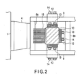
- FIG. 2 is a cross-sectional view showing an upper part of a movable rod portion of a vacuum valve of the embodiment.
- a main body frame 1 of a vacuum circuit breaker contains an operation mechanism 2 which opens and closes a main circuit.
- An upper support insulator 3 and a lower support insulator 4 are arranged with a distance therebetween and fixed to a side surface of the main body frame 1.
- An upper arm conductor 5a is fixed to the upper support insulator 3.
- Two upper main circuit conductors (first main circuit conductors) 6 are fixed to the upper arm conductor 5a so as to sandwich it at first ends thereof.
- An upper arm conductor 6b is provided at second ends of the upper main circuit conductors 6 to allow another electronic apparatus to connect thereto.
- An upper arm conductor 5c is fixed to an intermediate portion of the upper main circuit conductors 6.
- a fixed current-carrying rod end of a vacuum valve 7 is fixed to the upper arm conductor 5c, and has a pair of contacts, which are free to be connected/released to/from each other.
- a lower arm conductor 8a is fixed to the lower support insulator 4.
- Two lower main circuit conductors (second main circuit conductors) 9 are fixed to the lower arm conductor 8a so as to sandwich it at first ends thereof.
- a lower arm conductor 8b is provided at second ends of the lower main circuit conductors 9 to allow another electronic apparatus to connect thereto.
- a rectangular movable conductor 10 is connected to a movable side of the vacuum valve 7 along the axial direction by, for example, brazing, and further an operation movable rod 11 is connected thereto along the axial direction.
- an end of a movable current-carrying rod which is round and rod-shaped, is exposed outside the vacuum valve 7.
- the movable conductor 10 is electrically connected to the movable current-carrying rod end, and the operation movable rod 11 is mechanically connected to the movable conductor 10.
- the operation movable rod 11 is movably inserted between plates in intermediate portions of the lower main circuit conductors 9.
- first ends of three extendable flexible conductors 12 are respectively fixed by bolts 13 to a back surface and side surfaces of the four surfaces of the movable conductor 10.
- Each of the flexible conductors is formed of a plurality of thin plates, which are laminated.
- a second end of the flexible conductor 12 on one of the side surfaces of the movable conductor 10 is fixed to one of the lower main circuit conductors 9 by bolts 14, and a second end of the flexible conductor 12 on the other of the side surfaces of the movable conductor 10 is fixed to the other of the lower main circuit conductors 9 by bolts 14.
- a second end of the flexile conductor 12 on the back surface of the movable conductor 10 is fixed to a side surface of the lower arm conductor 8b by a bolt 14. Further, a radiating fin 15 is fixed to a front surface of the movable conductor 10.
- An insulating operation rod 16 extending along the axial direction is connected to the operation movable rod 11.
- One end of an operation lever 18, which rotates about a fixed pin 17, is connected to the insulating operation rod 16 via a movable pin 19.
- the end of the operation lever 18 is fixed by a double nut 20.
- the other end of the operation lever 18 is connected to the operation mechanism 2 via a movable pin 21.
- An insulating barrier 22 is provided between phases of the vacuum circuit breaker for insulation of main circuits, such as the vacuum valve 7, of the respective phases.
- Elements 23 are wheels 23 to move the vacuum circuit breaker.
- the number of parts is less as compared to the conventional art.
- the reduction in number of parts reduces the mass of the movable portion and can reduce the energy for operating the operation mechanism 2.
- the movable conductor 10 is connected to the movable current-carrying rod of the vacuum valve 7 in advance by brazing or the like during the process of manufacturing the vacuum valve 7. Therefore, the contact resistance between the vacuum valve 7 and the movable conductor 10 is very small, and it is unnecessary to count the movable conductor 10 as a part.
- the movable conductor 10 is rectangular, a plurality of flexible conductors 12 can be connected to the respective side surfaces. Therefore, the increase in contact resistance due to screw connection, which is most liable to increase the temperature, can be suppressed. Further, since the radiation fin 15 is attached, the increase in temperature can be suppressed.
- the rectangular movable conductor 10 is connected to one end of the current-carrying rod of the vacuum valve 7 and the movable conductors 12 are connected to three of the four side surfaces of the movable conductor 10 and the radiation fin 15 is attached to the remaining one side surface thereof. Therefore, the number of parts in the movable side, which is most liable to increase the temperature, can be small. Further, since the electrical resistance is reduced and radiation effect is improved, the current capacity can be increased.
- the present invention is not limited to the embodiment described above, but can be modified variously without departing from the sprit or scope of the invention.
- the movable conductor 10 of the embodiment is rectangular, it may be a polygonal body having three or more sides, so that flexible conductors 12 and a radiation fin 15 can be provided on the respective side surfaces.
- the number of flexible conductors 12 and radiation fins 15 can be determined to suit the current capacity of the vacuum circuit breaker. More specifically, at least one flexible conductor 12 can be connected to a side surface of the polygonal movable conductor 10.
- the movable conductor 10 be rectangular.
- the arrangement of the embodiment described above is particularly preferable to suppress the increase in temperature.
- a polygonal movable conductor is connected to the movable current-carrying rod end of the vacuum valve, and at least one movable conductor and a radiation fin are attached to the surfaces of the movable conductor. Therefore, the electrical resistance in the movable side, which is most liable to cause increase in temperature, can be less and the current capacity can be increased.
Landscapes
- Physics & Mathematics (AREA)
- Electromagnetism (AREA)
- High-Tension Arc-Extinguishing Switches Without Spraying Means (AREA)
Abstract
Description
- The present invention relates to a vacuum circuit breaker, which can enhance a current capacity.
- In a conventional vacuum circuit breaker, an upper main circuit conductor and a lower main circuit conductor are provided above and under a vacuum valve. The lower main circuit conductor is connected to a movable current-carrying rod of the vacuum valve via an extendable flexible conductor. Since the movable current-carrying rod of the vacuum valve is generally rod-shaped, a plate-like coupling conductor is connected to the movable current-carrying rod and one end of the flexible conductor is connected to the coupling conductor, while the other end thereof is connected to the lower main circuit conductor. A fixed current-carrying rod of the vacuum valve is fixed to the upper main circuit conductor by bolts (see, for example, Jpn. Pat. Appln. KOKAI Publication No.
2007-273383 pages FIG. 1 ). - The conventional vacuum circuit breaker described above has the following problems.
- As the current flowing therethrough increases, the electrical resistance in the main circuit components, such as the main circuit conductor, need be reduced. However, to reduce the electrical resistance, the sectional area of the main circuit components must be large, which causes an increase in size of the outer shape of the vacuum circuit breaker. Further, since the mass of the movable side inevitably increases, the operation energy to operate the movable side and the rigidity of the vacuum circuit breaker body need be increased.
- The portion of the main circuit components that most increases the electrical resistance is the movable side, which includes a number of connecting parts. Therefore, it is required to reduce the number of parts of the movable main circuit components and suppress the electrical resistance.
- It is an object of the present invention to provide a vacuum circuit breaker, in which the configuration of main circuit components in a movable side is simple to reduce the electrical resistance, thereby to enhance the current capacity.
- According to an aspect of the present invention, there is provided a vacuum circuit breaker comprising: a vacuum valve, a first main circuit conductor fixed to a fixed current-carrying rod end of the vacuum valve, a polygonal movable conductor connected to a movable current-carrying rod end of the vacuum valve, an operation movable rod connected to the movable conductor in an axial direction and connected to an operation mechanism, a second main circuit conductor, through which the operation movable rod is movably inserted, and at least one extendable flexible conductor, which connects side surfaces of the movable conductor and the second main circuit conductor.
- The invention can be more fully understood from the following detailed description when taken in conjunction with the accompanying drawings, in which:
-
FIG. 1 is a side view showing a configuration of a vacuum circuit breaker according an embodiment of the present invention; and -
FIG. 2 is a cross-sectional view showing an upper part of a movable rod portion of a vacuum valve of the embodiment. - An embodiment of the present invention will now be described with reference to the accompanying drawings.
- A vacuum circuit breaker according to one embodiment of the present invention will be described with reference to
FIGS. 1 and2 .FIG. 1 is a side view showing a configuration of a vacuum circuit breaker according an embodiment of the present invention, andFIG. 2 is a cross-sectional view showing an upper part of a movable rod portion of a vacuum valve of the embodiment. - As shown in
FIG. 1 , amain body frame 1 of a vacuum circuit breaker contains anoperation mechanism 2 which opens and closes a main circuit. Anupper support insulator 3 and alower support insulator 4 are arranged with a distance therebetween and fixed to a side surface of themain body frame 1. - An
upper arm conductor 5a is fixed to theupper support insulator 3. Two upper main circuit conductors (first main circuit conductors) 6 are fixed to theupper arm conductor 5a so as to sandwich it at first ends thereof. An upper arm conductor 6b is provided at second ends of the uppermain circuit conductors 6 to allow another electronic apparatus to connect thereto. Anupper arm conductor 5c is fixed to an intermediate portion of the uppermain circuit conductors 6. A fixed current-carrying rod end of a vacuum valve 7 is fixed to theupper arm conductor 5c, and has a pair of contacts, which are free to be connected/released to/from each other. - A
lower arm conductor 8a is fixed to thelower support insulator 4. Two lower main circuit conductors (second main circuit conductors) 9 are fixed to thelower arm conductor 8a so as to sandwich it at first ends thereof. Alower arm conductor 8b is provided at second ends of the lowermain circuit conductors 9 to allow another electronic apparatus to connect thereto. - A rectangular
movable conductor 10 is connected to a movable side of the vacuum valve 7 along the axial direction by, for example, brazing, and further an operationmovable rod 11 is connected thereto along the axial direction. Thus, an end of a movable current-carrying rod, which is round and rod-shaped, is exposed outside the vacuum valve 7. Themovable conductor 10 is electrically connected to the movable current-carrying rod end, and the operationmovable rod 11 is mechanically connected to themovable conductor 10. The operationmovable rod 11 is movably inserted between plates in intermediate portions of the lowermain circuit conductors 9. - As shown in
FIG. 2 , first ends of three extendableflexible conductors 12 are respectively fixed bybolts 13 to a back surface and side surfaces of the four surfaces of themovable conductor 10. Each of the flexible conductors is formed of a plurality of thin plates, which are laminated. A second end of theflexible conductor 12 on one of the side surfaces of themovable conductor 10 is fixed to one of the lowermain circuit conductors 9 bybolts 14, and a second end of theflexible conductor 12 on the other of the side surfaces of themovable conductor 10 is fixed to the other of the lowermain circuit conductors 9 bybolts 14. A second end of theflexile conductor 12 on the back surface of themovable conductor 10 is fixed to a side surface of thelower arm conductor 8b by abolt 14. Further, a radiatingfin 15 is fixed to a front surface of themovable conductor 10. - An
insulating operation rod 16 extending along the axial direction is connected to the operationmovable rod 11. One end of anoperation lever 18, which rotates about a fixedpin 17, is connected to theinsulating operation rod 16 via amovable pin 19. The end of theoperation lever 18 is fixed by adouble nut 20. The other end of theoperation lever 18 is connected to theoperation mechanism 2 via amovable pin 21. Aninsulating barrier 22 is provided between phases of the vacuum circuit breaker for insulation of main circuits, such as the vacuum valve 7, of the respective phases.Elements 23 arewheels 23 to move the vacuum circuit breaker. - In the above configuration, only the
flexible conductor 12 is connected to the lowermain circuit conductor 9 with screws on the movable side of the vacuum valve 7 without a plate-like coupling conductor, which is required in the conventional art. Thus, the number of parts is less as compared to the conventional art. The reduction in number of parts reduces the mass of the movable portion and can reduce the energy for operating theoperation mechanism 2. Themovable conductor 10 is connected to the movable current-carrying rod of the vacuum valve 7 in advance by brazing or the like during the process of manufacturing the vacuum valve 7. Therefore, the contact resistance between the vacuum valve 7 and themovable conductor 10 is very small, and it is unnecessary to count themovable conductor 10 as a part. - Further, since the
movable conductor 10 is rectangular, a plurality offlexible conductors 12 can be connected to the respective side surfaces. Therefore, the increase in contact resistance due to screw connection, which is most liable to increase the temperature, can be suppressed. Further, since theradiation fin 15 is attached, the increase in temperature can be suppressed. - In the vacuum circuit breaker of this embodiment, the rectangular
movable conductor 10 is connected to one end of the current-carrying rod of the vacuum valve 7 and themovable conductors 12 are connected to three of the four side surfaces of themovable conductor 10 and theradiation fin 15 is attached to the remaining one side surface thereof. Therefore, the number of parts in the movable side, which is most liable to increase the temperature, can be small. Further, since the electrical resistance is reduced and radiation effect is improved, the current capacity can be increased. - The present invention is not limited to the embodiment described above, but can be modified variously without departing from the sprit or scope of the invention. Although the
movable conductor 10 of the embodiment is rectangular, it may be a polygonal body having three or more sides, so thatflexible conductors 12 and aradiation fin 15 can be provided on the respective side surfaces. The number offlexible conductors 12 andradiation fins 15 can be determined to suit the current capacity of the vacuum circuit breaker. More specifically, at least oneflexible conductor 12 can be connected to a side surface of the polygonalmovable conductor 10. In terms of the arrangement of theflexible conductor 12 and theradiation fin 15, it is preferable that themovable conductor 10 be rectangular. The arrangement of the embodiment described above is particularly preferable to suppress the increase in temperature. - As has been detailed above, according to the present invention, a polygonal movable conductor is connected to the movable current-carrying rod end of the vacuum valve, and at least one movable conductor and a radiation fin are attached to the surfaces of the movable conductor. Therefore, the electrical resistance in the movable side, which is most liable to cause increase in temperature, can be less and the current capacity can be increased.
Claims (3)
- A vacuum circuit breaker characterized by comprising:a vacuum valve (7);a first main circuit conductor (6) fixed to a fixed current-carrying rod end of the vacuum valve (7);a polygonal movable conductor (10) connected to a movable current-carrying rod end of the vacuum valve (7);an operation movable rod (11) connected to the movable conductor (10) in an axial direction and connected to an operation mechanism (2);a second main circuit conductor (9), through which the operation movable rod (11) is movably inserted; andat least one extendable flexible conductor (12), which connects side surfaces of the movable conductor (10) and the second main circuit conductor (9).
- The vacuum circuit breaker according to claim 1, characterized by further comprising a radiation fin (15) attached to one of the side surfaces of the movable conductor (10).
- The vacuum circuit breaker according to claim 1 or 2, characterized in that the movable conductor (10) has a rectangular body and the flexible conductors (12) are connected to a back surface and side surfaces of the movable conductor (10).
Applications Claiming Priority (1)
| Application Number | Priority Date | Filing Date | Title |
|---|---|---|---|
| JP2008228942A JP2010062092A (en) | 2008-09-05 | 2008-09-05 | Vacuum breaker |
Publications (2)
| Publication Number | Publication Date |
|---|---|
| EP2161729A2 true EP2161729A2 (en) | 2010-03-10 |
| EP2161729A3 EP2161729A3 (en) | 2012-01-18 |
Family
ID=41396355
Family Applications (1)
| Application Number | Title | Priority Date | Filing Date |
|---|---|---|---|
| EP09010601A Withdrawn EP2161729A3 (en) | 2008-09-05 | 2009-08-18 | Vaccum circuit breaker |
Country Status (5)
| Country | Link |
|---|---|
| US (1) | US8283590B2 (en) |
| EP (1) | EP2161729A3 (en) |
| JP (1) | JP2010062092A (en) |
| KR (1) | KR101072419B1 (en) |
| CN (1) | CN101667506B (en) |
Cited By (2)
| Publication number | Priority date | Publication date | Assignee | Title |
|---|---|---|---|---|
| WO2015191149A1 (en) * | 2014-06-09 | 2015-12-17 | Eaton Corporation | Modular vacuum interruption apparatus |
| WO2018197150A1 (en) * | 2017-04-24 | 2018-11-01 | Siemens Aktiengesellschaft | Connection element for a moving contact of a vacuum interrupter and gas-insulated switchgear assembly having a connection element for a moving contact of a vacuum interrupter |
Families Citing this family (7)
| Publication number | Priority date | Publication date | Assignee | Title |
|---|---|---|---|---|
| US9177742B2 (en) | 2011-10-18 | 2015-11-03 | G & W Electric Company | Modular solid dielectric switchgear |
| DE102012213709A1 (en) * | 2012-08-02 | 2014-02-06 | Continental Automotive Gmbh | A method for detecting a fault of a motor assembly with an electric machine and engine control unit |
| EP2747113B1 (en) * | 2012-12-20 | 2015-10-21 | ABB Technology AG | Circuit-breaker pole part with a flexible conductor for connecting a movable electrical contact |
| KR101723757B1 (en) * | 2013-01-09 | 2017-04-05 | 미쓰비시덴키 가부시키가이샤 | Vacuum circuit breaker |
| WO2015111725A1 (en) * | 2014-01-24 | 2015-07-30 | 矢崎総業株式会社 | Service plug |
| EP3444831B1 (en) * | 2016-04-12 | 2020-03-25 | Mitsubishi Electric Corporation | Vacuum circuit breaker and gas-insulated switchgear and air-insulated switchgear having integrated vacuum circuit breaker |
| CN110120321B (en) * | 2018-02-06 | 2020-11-24 | 浙江圣曦电气股份有限公司 | A closed low-voltage circuit breaker |
Citations (1)
| Publication number | Priority date | Publication date | Assignee | Title |
|---|---|---|---|---|
| JP2007273383A (en) | 2006-03-31 | 2007-10-18 | Toshiba Corp | Vacuum circuit breaker |
Family Cites Families (10)
| Publication number | Priority date | Publication date | Assignee | Title |
|---|---|---|---|---|
| SU1601653A1 (en) | 1988-12-06 | 1990-10-23 | В.А, Сказко | Three-pole high-voltage vacuum switch |
| JPH04109524A (en) | 1990-08-30 | 1992-04-10 | Toshiba Corp | Vacuum circuit breaker |
| JPH08222090A (en) | 1995-02-10 | 1996-08-30 | Toshiba Corp | Vacuum circuit breaker |
| DE19505370C2 (en) | 1995-02-17 | 2000-11-02 | Abb Patent Gmbh | Vacuum switch |
| US5753875A (en) * | 1996-10-15 | 1998-05-19 | Eaton Corporation | Heat sink for contact stems of a vacuum interrupter and a vacuum interrupter therewith |
| KR200224244Y1 (en) | 1998-01-21 | 2001-06-01 | 이종수 | structure of push rod in vacuum circuit breaker |
| KR200212859Y1 (en) | 1998-11-19 | 2001-06-01 | 이종수 | Main Circuit Terminal Structure of Vacuum Circuit Breaker_ |
| DE102004047259B3 (en) | 2004-09-24 | 2006-05-04 | Siemens Ag | Solids-insulated switch pole with front-side moving contact connection |
| DE102004050786C5 (en) | 2004-10-14 | 2008-03-06 | Siemens Ag | Coupling device with heat sink |
| JP2006140038A (en) | 2004-11-12 | 2006-06-01 | Toshiba Corp | Vacuum circuit breaker |
-
2008
- 2008-09-05 JP JP2008228942A patent/JP2010062092A/en active Pending
-
2009
- 2009-08-12 US US12/539,921 patent/US8283590B2/en not_active Expired - Fee Related
- 2009-08-18 EP EP09010601A patent/EP2161729A3/en not_active Withdrawn
- 2009-08-26 KR KR1020090079049A patent/KR101072419B1/en not_active Expired - Fee Related
- 2009-08-27 CN CN2009101683122A patent/CN101667506B/en not_active Expired - Fee Related
Patent Citations (1)
| Publication number | Priority date | Publication date | Assignee | Title |
|---|---|---|---|---|
| JP2007273383A (en) | 2006-03-31 | 2007-10-18 | Toshiba Corp | Vacuum circuit breaker |
Cited By (5)
| Publication number | Priority date | Publication date | Assignee | Title |
|---|---|---|---|---|
| WO2015191149A1 (en) * | 2014-06-09 | 2015-12-17 | Eaton Corporation | Modular vacuum interruption apparatus |
| US9396896B2 (en) | 2014-06-09 | 2016-07-19 | Eaton Corporation | Modular vacuum interruption apparatus |
| WO2018197150A1 (en) * | 2017-04-24 | 2018-11-01 | Siemens Aktiengesellschaft | Connection element for a moving contact of a vacuum interrupter and gas-insulated switchgear assembly having a connection element for a moving contact of a vacuum interrupter |
| CN110537239A (en) * | 2017-04-24 | 2019-12-03 | 西门子股份公司 | The gas isolated switchgear of the terminal component of movement contact for vacuum switch tube and the terminal component with the movement contact for vacuum switch tube |
| CN110537239B (en) * | 2017-04-24 | 2022-04-29 | 西门子股份公司 | Terminal elements and gas-insulated switchgear |
Also Published As
| Publication number | Publication date |
|---|---|
| KR101072419B1 (en) | 2011-10-11 |
| CN101667506A (en) | 2010-03-10 |
| KR20100029030A (en) | 2010-03-15 |
| US20100059480A1 (en) | 2010-03-11 |
| CN101667506B (en) | 2013-04-24 |
| JP2010062092A (en) | 2010-03-18 |
| EP2161729A3 (en) | 2012-01-18 |
| US8283590B2 (en) | 2012-10-09 |
Similar Documents
| Publication | Publication Date | Title |
|---|---|---|
| US8283590B2 (en) | Vacuum circuit breaker | |
| KR100996791B1 (en) | Main Circuit Terminal Assembly of Vacuum Circuit Breaker | |
| JP4946920B2 (en) | Vacuum switch | |
| CN106463293A (en) | Electrical switching apparatus, and jumper and associated method therefor | |
| JP2015527720A (en) | Contact assembly and vacuum switch including the same | |
| JP2009240095A (en) | Vacuum breaker | |
| JP6990294B2 (en) | Circuit breaker for gas-insulated switchgear | |
| US9012801B2 (en) | Flexible shunt for vacuum circuit breaker | |
| CN100386834C (en) | Switching device | |
| US9966741B2 (en) | Integrated connector for backplane of a draw out breaker chassis | |
| US20100300852A1 (en) | Low-voltage, medium-voltage or high-voltage switchgear assembly with at least one moveable contact | |
| JP2009277386A (en) | Vacuum circuit breaker | |
| EP2306482B1 (en) | Main circuit terminal assembly for vacuum circuit breaker | |
| JP5210582B2 (en) | Vacuum switchgear | |
| CN108885959B (en) | Vacuum circuit breaker, gas insulated switchgear equipped with vacuum circuit breaker, and air insulated switchgear | |
| JP4580767B2 (en) | Solid insulated conductor | |
| KR200473205Y1 (en) | Flexible shunt in current carrying part of vacuum circuit breaker | |
| HK1261127B (en) | Vacuum circuit breaker and gas-insulated switchgear and air-insulated switchgear having integrated vacuum circuit breaker | |
| HK1261127A1 (en) | Vacuum circuit breaker and gas-insulated switchgear and air-insulated switchgear having integrated vacuum circuit breaker | |
| WO2017022510A1 (en) | Switching device and switch gear | |
| JP2003324818A (en) | Flexible lead | |
| CN118575247A (en) | Ultrafast moving conductor with removable core pin | |
| JPS6336093B2 (en) | ||
| JP2005261043A (en) | Switch and switchboard unit | |
| CN111971772A (en) | Flexible conductor for isolating switch and isolating switch |
Legal Events
| Date | Code | Title | Description |
|---|---|---|---|
| PUAI | Public reference made under article 153(3) epc to a published international application that has entered the european phase |
Free format text: ORIGINAL CODE: 0009012 |
|
| 17P | Request for examination filed |
Effective date: 20090818 |
|
| AK | Designated contracting states |
Kind code of ref document: A2 Designated state(s): AT BE BG CH CY CZ DE DK EE ES FI FR GB GR HR HU IE IS IT LI LT LU LV MC MK MT NL NO PL PT RO SE SI SK SM TR |
|
| AX | Request for extension of the european patent |
Extension state: AL BA RS |
|
| PUAL | Search report despatched |
Free format text: ORIGINAL CODE: 0009013 |
|
| AK | Designated contracting states |
Kind code of ref document: A3 Designated state(s): AT BE BG CH CY CZ DE DK EE ES FI FR GB GR HR HU IE IS IT LI LT LU LV MC MK MT NL NO PL PT RO SE SI SK SM TR |
|
| AX | Request for extension of the european patent |
Extension state: AL BA RS |
|
| RIC1 | Information provided on ipc code assigned before grant |
Ipc: H01H 9/52 20060101ALI20111209BHEP Ipc: H01H 33/666 20060101ALI20111209BHEP Ipc: H01H 1/58 20060101AFI20111209BHEP |
|
| GRAP | Despatch of communication of intention to grant a patent |
Free format text: ORIGINAL CODE: EPIDOSNIGR1 |
|
| RIC1 | Information provided on ipc code assigned before grant |
Ipc: H01H 33/666 20060101ALI20150827BHEP Ipc: H01H 9/52 20060101ALI20150827BHEP Ipc: H01H 1/58 20060101AFI20150827BHEP |
|
| INTG | Intention to grant announced |
Effective date: 20150921 |
|
| STAA | Information on the status of an ep patent application or granted ep patent |
Free format text: STATUS: THE APPLICATION IS DEEMED TO BE WITHDRAWN |
|
| 18D | Application deemed to be withdrawn |
Effective date: 20160202 |