EP2161692A2 - Mixed reality space image providing apparatus - Google Patents
Mixed reality space image providing apparatus Download PDFInfo
- Publication number
- EP2161692A2 EP2161692A2 EP09169777A EP09169777A EP2161692A2 EP 2161692 A2 EP2161692 A2 EP 2161692A2 EP 09169777 A EP09169777 A EP 09169777A EP 09169777 A EP09169777 A EP 09169777A EP 2161692 A2 EP2161692 A2 EP 2161692A2
- Authority
- EP
- European Patent Office
- Prior art keywords
- space image
- mixed reality
- data
- client
- reality space
- Prior art date
- Legal status (The legal status is an assumption and is not a legal conclusion. Google has not performed a legal analysis and makes no representation as to the accuracy of the status listed.)
- Granted
Links
Images





Classifications
-
- G—PHYSICS
- G06—COMPUTING OR CALCULATING; COUNTING
- G06T—IMAGE DATA PROCESSING OR GENERATION, IN GENERAL
- G06T19/00—Manipulating three-dimensional [3D] models or images for computer graphics
- G06T19/006—Mixed reality
-
- G—PHYSICS
- G06—COMPUTING OR CALCULATING; COUNTING
- G06F—ELECTRIC DIGITAL DATA PROCESSING
- G06F30/00—Computer-aided design [CAD]
- G06F30/20—Design optimisation, verification or simulation
-
- G—PHYSICS
- G06—COMPUTING OR CALCULATING; COUNTING
- G06T—IMAGE DATA PROCESSING OR GENERATION, IN GENERAL
- G06T19/00—Manipulating three-dimensional [3D] models or images for computer graphics
-
- A—HUMAN NECESSITIES
- A63—SPORTS; GAMES; AMUSEMENTS
- A63F—CARD, BOARD, OR ROULETTE GAMES; INDOOR GAMES USING SMALL MOVING PLAYING BODIES; VIDEO GAMES; GAMES NOT OTHERWISE PROVIDED FOR
- A63F2300/00—Features of games using an electronically generated display having two or more dimensions, e.g. on a television screen, showing representations related to the game
- A63F2300/80—Features of games using an electronically generated display having two or more dimensions, e.g. on a television screen, showing representations related to the game specially adapted for executing a specific type of game
- A63F2300/8082—Virtual reality
-
- G—PHYSICS
- G06—COMPUTING OR CALCULATING; COUNTING
- G06F—ELECTRIC DIGITAL DATA PROCESSING
- G06F3/00—Input arrangements for transferring data to be processed into a form capable of being handled by the computer; Output arrangements for transferring data from processing unit to output unit, e.g. interface arrangements
- G06F3/01—Input arrangements or combined input and output arrangements for interaction between user and computer
- G06F3/011—Arrangements for interaction with the human body, e.g. for user immersion in virtual reality
-
- G—PHYSICS
- G06—COMPUTING OR CALCULATING; COUNTING
- G06F—ELECTRIC DIGITAL DATA PROCESSING
- G06F30/00—Computer-aided design [CAD]
-
- G—PHYSICS
- G06—COMPUTING OR CALCULATING; COUNTING
- G06T—IMAGE DATA PROCESSING OR GENERATION, IN GENERAL
- G06T15/00—Three-dimensional [3D] image rendering
-
- G—PHYSICS
- G09—EDUCATION; CRYPTOGRAPHY; DISPLAY; ADVERTISING; SEALS
- G09G—ARRANGEMENTS OR CIRCUITS FOR CONTROL OF INDICATING DEVICES USING STATIC MEANS TO PRESENT VARIABLE INFORMATION
- G09G5/00—Control arrangements or circuits for visual indicators common to cathode-ray tube indicators and other visual indicators
Definitions
- the present invention relates to a mixed reality space image providing apparatus, which provides users with a mixed reality space image made of a combination of computer graphics and a real space image.
- CAD computer-aided design
- This type of system has, for example, a function to simulate a movement of each of the components before actually assembling the mechanism, in order to assist development of a control program for controlling active components such as an actuator and a motor, and a sensor.
- a control program for controlling active components such as an actuator and a motor, and a sensor.
- the present invention is directed to an apparatus and a method for providing a mixed reality space image facilitating the sensuous recognition of a simulation result.
- a mixed reality space image providing apparatus as specified in claim 1.
- a mixed reality space image providing system as specified in claims 2 to 9.
- a method as specified in claim 10.
- a computer-executable program as specified in claims 11 and 12.
- a computer-readable recording medium as specified in claim 13.
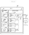
- Fig. 1 illustrates a basic configuration of a three-dimensional CAD system according to an exemplary embodiment of the present invention.
- Fig. 2 is a block diagram illustrating a hardware configuration of each of clients of the three-dimensional CAD system.
- Fig. 3 is a block diagram illustrating a configuration of a server.
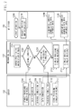
- Fig. 4 illustrates flows of commands and data among a mixed reality (MR) system, a mechanical CAD, and a server according to a first exemplary embodiment of the present invention.
- MR mixed reality
- Fig. 5 illustrates a user operating a virtual camera.
- Fig. 6 illustrates a detailed configuration of the MR system.
- Fig. 7 illustrates flows of commands and data among the MR system, the mechanical CAD, and the server according to a second exemplary embodiment of the present invention.
- Fig. 8 illustrates flows of commends and data between the MR system and the server according to a third exemplary embodiment of the present invention.
- FIG. 1 illustrates a basic configuration of a three-dimensional CAD system according to an exemplary embodiment of the present invention.
- a server 100 constitutes a brain unit of the system.
- a mechanical CAD 110 is a client used to design a mechanism unit, which is a part of an apparatus.
- An electric CAD 120 is a client used to design an electrical circuit unit of the apparatus.
- a firmware development support tool 130 is a client used to develop and aid the development of a program (firmware) that controls the mechanism unit and the electrical circuit unit of the apparatus.
- An optical CAD 140 is a client used to design optical components including a lens unit.
- An MR system 150 has a providing function to combine an actually captured image (video image in a real space) with a CG image to display the combined image.
- the server 100 and each of the clients 110 through 150 are connected to each other via a network 160. Then, various types of data are transmitted between each of the clients 110 through 150 and the server 100, and also between individual clients 110 through 150 through the server 100.
- the server 100 includes a calculation unit 101 and a data storage unit 102.
- the calculation unit 101 extracts necessary data from the data storage unit 102, stores data, and performs calculation processing on the data in response to a request from each of the clients 110 through 150. Further, the calculation unit 101 generates a three-dimensional model of an apparatus to be designed, generates data for simulating various movements of the apparatus, and stores the data in the data storage unit 102 or causes the data to be downloaded to each of the clients 110 through 150.
- the configuration of each of the clients 110 through 150 is described below.
- the mechanical CAD 110 builds up a mechanical design environment according to, for example, shape and operation data of mechanism parts to be used in design and an application for designing the mechanism unit by combining those mechanism parts.
- the electric CAD 120 builds up a circuit designing environment according to, for example, data about various circuit parts, a circuit configuration, a circuit diagram, and various movement parameters with respect to the electrical circuit of the apparatus and an application that designs a circuit based on those data.
- the optical CAD 140 builds up an optical designing environment according to data about an optical configuration of the lens unit such as a lens shape and an optical characteristics, and an application that optically designs, for example, the lens unit based on those data.
- the firmware development support tool 130 includes a firmware, i.e., a program, which controls movements of a mechanism unit, an electric circuit, an optical mechanism unit of the apparatus.
- the firmware development support tool 130 is configured to, as it will be described later, share the latest data or the designing environment of each of the other clients (the mechanical CAD 110, the electric CAD 120, and the optical CAD 140), thereby performing a movement simulation in real time.
- the MR system 150 superimposes the three-dimensional models having been formed within the server 100 on the video image in the real space and displays the thus combined image.
- data required for the design is read out from the data storage unit 102 of the server 100 and is then supplied to each of the clients 110 through 150.
- the designing operation performed by each of the clients 110 through 150 is uploaded to the calculation unit 101 of the server 100 in real time to generate a three-dimensional model of the apparatus (mechanism unit) within the server 100.
- Data of the three-dimensional model is stored in the data storage unit 102 and further is downloaded to a client as a request source in response to a request from each of the clients 110 through 150.
- the client as the request source can display the thus downloaded three-dimensional model after reflecting its designing data onto the thus downloaded three-dimensional model, as required, and can perform a simulation with the three-dimensional model.
- Fig. 2 is a block diagram illustrating an example of a hardware configuration of each of the clients 110 through 150 in the three-dimensional CAD system according to the present exemplary embodiment.
- Each of the clients 110 through 150 can be a general-purpose computer 200.
- the computer 200 includes a central processing unit (CPU) 201 as a control unit of the computer 200, and a read-only memory (ROM) 202, which stores a boot program executed by the CPU 201 when starting up the computer 200 and various programs running on hardware of the computer 200.
- a RAM 203 stores a program executed by the CPU 201 and data to be used by the CPU 201 for calculation.
- a communication interface (I/F) 204 makes a communication with the server 100 via the network 160.
- the computer 200 further includes a display 205, a printer 206, a mouse 207, a keyboard 208, a hard disk drive 209, a floppy disk (FD) drive 210, and a compact disc read-only memory (CD-ROM) drive 211.
- a display 205 a printer 206, a mouse 207, a keyboard 208, a hard disk drive 209, a floppy disk (FD) drive 210, and a compact disc read-only memory (CD-ROM) drive 211.
- the application program, the operating system, and the others, which cause the clients to work as the CAD, are stored in the hard disk drive 209.
- the CPU 201 operates based on the program (which is loaded on the RAM 203 when being executed) stored in the ROM 202 or the hard disk drive 209 to control each unit within the computer 200.
- the communication I/F 204 makes communication with the other devices (with the clients or the server) via the network 160.
- the hard disk drive 209 stores a program and data for realizing a function that the computer 200 provides to the users, and provides the program and data to the CPU 201 through the RAM 203.
- the FD drive 210 and the CD-ROM drive 211 read the program and data from a removable medium, such as an FD 212 or a CD-ROM 213, and supply the thus read program and data to the RAM 203.
- An internal bus 214 connects the devices within the computer 200 to each other.
- the program executed by the CPU 201 is modified so as to realize a function of the server 100, the function of the server 100 also can be realized by the computer 200 illustrated in Fig. 2 .
- Fig. 3 is a block diagram illustrating an example of a functional configuration of the server 100.
- the server 100 includes the calculation unit 101 and the data storage unit 102.
- the data storage unit 102 is implemented by a storage device, e.g., the hard disk drive 209.
- the data storage unit 102 stores and accumulates mechanical data 301, electrical data 303, optical data 304, and firmware data 302, which correspond to the mechanical CAD 110, the electric CAD 120, the optical CAD 140, the firmware development support tool 130, and the MR system 150, respectively, serving as clients.
- the mechanical data 301 corresponding to the mechanical CAD 110 contains data of various mechanical parts required for the mechanical design, data of configurations of active components such as an actuator or a motor, a size, a shape, and the other various characteristics.
- the mechanical data 301 corresponding to the mechanical CAD 110 contains mechanism model data designed in the mechanical CAD 110 of the client.
- the mechanical data 301 corresponding to the mechanical CAD 110 manages a shape, an attribute, or the like of the parts registered, and sends data required by the calculation unit 101 in response to a request from the processor unit 309. Similar processing is performed in each of the electrical data 303, the optical data 304, and the firmware data 302.
- the electrical data 303 contains data about the parts of the electrical circuit and electrical circuit data designed by the electric CAD 120.
- the optical data 304 contains data of the optical parts and optical design data designed by the optical CAD 140.
- the firmware data 302 contains firmware data generated by the firmware development support tool 130.
- the calculation unit 101 which is implemented by, for example, the CPU 201, includes a data conversion unit 305 for mechanical data, a data conversion unit 306 for firmware data, a data conversion unit 307 for electrical data, and a data conversion unit 308 for optical data. Further, the processor unit 309 performs calculation processing on the data converted by the data conversion units 305 through 308 based on the program.
- the data conversion units 305 through 308 read out the mechanical data 301, the electrical data 303, the optical data 304, and the firmware data 302 from the data storage unit 102, respectively, based on an instruction from each of the clients. Then, for example, in the mechanical design, the mechanical data is converted in accordance with the designing environment of the client as the request source.
- the registered parts-data read out from the mechanical data 301 is converted with respect to a display scale, mounting positions of the parts to the device, orientation of the device, or the like in accordance with characteristics and specification which can be handled by the client and are preliminary registered.
- the mechanical CAD 110 is the client as the request source
- the data conversion is not essential for the client as the request source. Accordingly, the design data can be shared between the different CAD systems.
- the converted data is sent to the processor unit 309 to be further provided to the client as the request source.
- the electrical data 303 is read out in accordance with an instruction from each of the clients 110 through 140. Then, the electrical data 303 is converted into such a certain data form in the data conversion unit 307 that the electrical data 303 can be managed by the client as the request source, and thereafter the converted data is supplied to the client as the request source through the processor unit 309.
- each of the other optical data 304 and the firmware data 302 is converted into a certain form in compliance with a request from each of the clients as the request source, and thereafter the respective converted data is supplied to each client through the processor unit 309.
- a request signal generated by the mechanical CAD 110 as the client is supplied to the processor unit 309 within the calculation unit 101 of the server 100 via the network 160.
- the processor unit 309 requests essential data from the data storage unit 102 based on the request signal and the program stored in the RAM 203 or the hard disk 209.
- the data storage unit 102 reads out the requested data 301, 302, 303, and 304, and thereafter sends them to the respective corresponding data conversion units 305, 306, 307, and 308.
- Each of the data conversion units 305 through 308 converts data based on a data conversion program stored in the RAM 203 or the hard disk 209, and thereafter sends the converted data to the processor unit 309.
- the processor unit 309 performs calculation for a simulation or the like with the converted data provided by the processor unit 309, and thereafter sends the calculation result to the mechanical CAD 110, i.e., the client as the request source, via the network 160.
- the mechanical CAD 110 displays the calculation result on the display 205 and stores the calculation result in the hard disk 209 in the form of a file.
- the above described flow is common to all of the clients 110, 120, 130, and 140.
- Fig. 4 illustrates a flow of commands and data between the client as the request source and the server 100.
- FIG. 4 an example is illustrated in which the MR system 150 is the client as the request source.
- Fig. 4 illustrates an actual bi-directional flow of various types of data transmitted between the server 100 and the MR system 150 and how to manage the data.
- Fig. 4 illustrates processing of various operations and transmission and reception of data when the mechanism designer (the user of the MR system 150) designs the mechanism unit by using the three-dimensional CAD system of the present exemplary embodiment.
- the processing flow proceeds top-to-bottom. Each processing can be performed at the same time.
- step S400 the mechanism designer starts up the MR system 150, and observes a model, which the mechanism designer is designing in the mechanical CAD 110, on the MR space while superimposing the model on the actually captured image.
- a camera is used as the model as illustrated in Fig. 5 .
- Fig. 5 illustrates the MR space.
- the camera 501 is the computer graphics drawn by the mechanical CAD 110 based on a point of view of the mechanism designer.
- a displayed position and orientation moves in conjunction with the state of a position and orientation of a mock-up 505 having a shape of a camera with a position and orientation sensor.
- the position and orientation of the mock-up 505 is measured by an object position and orientation measurement unit 607 mounted on a head mounted display (HMD) 504.
- the camera 501 includes a shutter button 502, which moves in conjunction with a shutter button of the mock-up 505.
- a user 503 wears the HMD 504 to operate the camera 501.
- Fig. 6 illustrates configurations of the HMD 504 and the MR system 150.
- the MR system 150 includes a real image input unit 602, an image combining unit 603, a mixed reality image output unit 604, a camera position and orientation measurement unit 605, a virtual object input unit 606, and an object position and orientation measurement unit 607.
- the HMD 504 includes a left camera 632, a right camera 633, a left real image output unit 634, a right real image output unit 635, a mixed reality image input unit 636, and an image display unit 637.
- a position and orientation sensor is connected to a finger of the user 503.
- the user 503 holds the mock-up 505 to operate the camera 501.
- the user 503 is about to push the shutter button 502 of the camera 501.
- the finger of the user 503 gradually approaches the shutter button 502.
- a simulation that the user 503 pushes the shutter button 502 of the camera 501 starts when the finger of the user 503 reaches the position at which the user 503 pushes the shutter button 502.
- step S400 after the MR system 150 has started, then in step S401, the position and orientation sensor measures the position of the finger of the user 503.
- step S402 the MR system 150 determines whether the finger of the user 503 is located at a predetermined position where the shutter button 502 is pushed. If the finger of the user 503 is located at the predetermined position (YES in step S402), the processing proceeds to step S406. If the finger of the user 503 is not located at the predetermined position (NO in step S402), the processing proceeds to step S403.
- step S403 the MR system 150 determines whether the position of the finger of the user 503 is about to reach the predetermined position although not yet reaching the predetermined position. If the MR system 150 determines that the finger of the user 503 is almost about to reach the predetermined position (YES in step S403), the processing proceeds to step S408.
- step S408 the server 100 performs a simulation corresponding to the case where the finger of the user 503 has reached the predetermined position.
- step S409 the server 100 stores the simulation result of step S408 in the data storage unit 102.
- step S406 the server 100 extracts a preceding simulation result from the data storage unit 102.
- step S412 the server 100 converts the preceding simulation result into data for the mechanical CAD 110 and then transmits the thus-converted data to the mechanical CAD 110. Then, in the server 100, the processing proceeds to step S407.
- step S410 the mechanical CAD 110 obtains the preceding simulation result from the server 100 and displays the obtained preceding simulation result.
- step S404 the MR system 150 superimposes computer graphics displayed in step S410 on the actually captured image to display the combined image.
- step S407 the server 100 performs an original simulation.
- step S413 the server 100 converts the original simulation into data for the mechanical CAD 110 and transmits the data to the mechanical CAD 110.
- step S411 the mechanical CAD 110 obtains the original simulation result from the server 100 and displays the obtained original simulation result.
- step S405 the MR system 150 superimposes computer graphics displayed in step S411 on the actually captured image to display the combined image.
- the three-dimensional CAD system predicts an environment of the real space according to the position of the finger of the user 503 and determines a preceding simulation, so that the user 503 can have an experience with the MR space without experiencing any delay.
- a second exemplary embodiment of the present invention has a similar basic configuration to that of the first exemplary embodiment.
- a difference between the second exemplary embodiment and the first exemplary embodiment is a condition for starting a simulation.
- the MR system 150 starts a simulation in the server 100.
- the mechanical CAD 110 starts a simulation in the server 100.
- step S700 the MR system 150 starts its operation.
- step S714 the MR system 150 measures a position and orientation of the mock-up 505 and sends the measure value to the mechanical CAD 110.
- step S701 the mechanical CAD 110 receives the measured value about the position and orientation of the mock-up 505 from the MR system 150 and sets the measured value to the camera 501 with respect to the position and orientation of the camera 501.
- step S702 if the mechanical CAD 110 is under the condition to perform an original simulation (YES in step S702), the processing proceeds to step S706. If the mechanical CAD 110 is not under the condition to perform an original simulation (NO in step S702), the processing proceeds to step S703.
- step S703 the mechanical CAD 110 determines whether the mechanical CAD 110 is under the condition to perform a preceding simulation.
- the condition to perform a preceding simulation (order of the simulation) can be set, for example, such that a time period to be taken in the processing becomes the minimum. If the mechanical CAD 110 determines that the mechanical CAD 110 is under the condition to perform a preceding simulation (YES in step S703), the processing proceeds to step S710. If the mechanical CAD 110 determines that the mechanical CAD 110 is not under the condition to perform a preceding simulation (NO in step S703), the processing proceeds to step S701.
- step S710 the server 100 starts the preceding simulation.
- the order to perform the simulation is changed, resulting in preventing the simulation from delaying.
- step S711 the server 100 causes the data storage unit 102 to store the result of the preceding simulation.
- step S706 the server 100 extracts the result of the preceding simulation from the data storage unit 102.
- step S707 the server 100 converts the result of the preceding simulation into data for the mechanical CAD 110, and then the processing proceeds to step S708.
- step S712 the mechanical CAD 110 receives the result of the preceding simulation and displays the result.
- step S704 the MR system 150 combines the actually captured image with the computer graphics displayed in step S712 and displays the thus-combined image.
- step S708 the server 100 performs the simulation under the present condition.
- step S709 the server 100 converts the result of the simulation into data for the mechanical CAD 110 and sends the data to the mechanical CAD 110, and then the processing proceeds to step S713.
- step S713 the mechanical CAD 110 receives the result of the original simulation and displays the result.
- step S705 the MR system 150 combines the actually captured image with the computer graphics displayed in step S713 and displays the combined image.
- a basic configuration of a third exemplary embodiment of the present invention is similar to that of the first exemplary embodiment.
- the third exemplary embodiment is different from the first exemplary embodiment in a control method performed when the simulation delays.
- the delay of a simulation is covered by performing a preceding simulation.
- a simple simulation method capable of performing high-speed processing without delay, although incapable of performing a high-accuracy simulation, is prepared to avoid the delay of a simulation.
- step S800 the MR system 150 starts its operation.
- step S801 the MR system 150 checks the movement of the user 503.
- step S802 the MR system 150 determines whether to perform a simulation. If the MR system 150 determines to perform a simulation (YES in step S802), the processing proceeds to step S807 and step S809. Steps S807 and step S809 are concurrently performed.
- step S807 the server 100 performs an original simulation.
- step S809 the server 100 performs a simple simulation without delaying.
- step S808 if processing in step S807 has been completed, the server 100 converts the result of processing in step S807 into data and sends the data to the MR system 150. Further, if the processing in step S807 has not been completed, the server 100 converts the result of processing in step S809 into data and sends the data to the MR system 150.
- step S806 the MR system 150 draws a simulation result and combines the simulation result with the real captured image to display the combined image. Then, the processing proceeds to step S801.
- a designing environment in which an MR system, a mechanical CAD, an electric CAD, a software tool, and an optical CAD are well combined can be realized to perform a mutual simulation.
- a complete simulation can be performed even before a trial model is assembled.
- the user 503 can sensuously check the movement of the trial model.
- a development design environment is dramatically developed and the number of simulated designs and the number of trial models can be reduced, resulting in dramatically reducing a development design cost.
- each of the clients can share design data made by the respective clients.
- a simulation can be performed by combining elements, for example, a mechanism, an electrical circuit, software, and optical parts, which are individually designed by each of the clients. Therefore, a perfect simulation can be performed even before the trial model is assembled and thus the development design environment is dramatically improved. As a result, the number of simulated designs and the number of trial models can be reduced, thereby dramatically reducing the development design cost.
- a designed object can be simulated while the object is still in the developmental stage. Still further, since the movement of the designed object can be sensuously checked in three dimensions, parallel designing with the other designers, collaborative study with the other designers, and reduction of mistakes in specification can be achieved.
Landscapes
- Engineering & Computer Science (AREA)
- Physics & Mathematics (AREA)
- Theoretical Computer Science (AREA)
- Computer Hardware Design (AREA)
- General Engineering & Computer Science (AREA)
- General Physics & Mathematics (AREA)
- Computer Graphics (AREA)
- Software Systems (AREA)
- Evolutionary Computation (AREA)
- Geometry (AREA)
- Processing Or Creating Images (AREA)
Abstract
Description
- The present invention relates to a mixed reality space image providing apparatus, which provides users with a mixed reality space image made of a combination of computer graphics and a real space image.
- Conventionally, a three-dimensional computer-aided design (CAD) system has been used in the field of a mechanical design. In this field, a design can be made while a mechanism and components of the mechanism are displayed in three dimensions.
- This type of system has, for example, a function to simulate a movement of each of the components before actually assembling the mechanism, in order to assist development of a control program for controlling active components such as an actuator and a motor, and a sensor. Such a three-dimensional CAD system for simulation is discussed in Japanese Patent Application Laid-open No.
2006-195971 - However, in the CAD system as discussed in Japanese Patent Application Laid-open No.
2006-195971 - The present invention is directed to an apparatus and a method for providing a mixed reality space image facilitating the sensuous recognition of a simulation result.
- According to a first aspect of the present invention, there is provided a mixed reality space image providing apparatus as specified in claim 1. According to a second aspect of the present invention, there is provided a mixed reality space image providing system as specified in
claims 2 to 9. According to a third aspect of the present invention, there is provided a method as specified in claim 10. According to a fourth aspect of the present invention, there is provided a computer-executable program as specified in claims 11 and 12. According to a fifth aspect of the present invention, there is provided a computer-readable recording medium as specified in claim 13. - Further features and aspects of the present invention will become apparent from the following detailed description of exemplary embodiments with reference to the attached drawings.
- The accompanying drawings, which are incorporated in and constitute a part of the specification, illustrate exemplary embodiments, features, and aspects of the invention and, together with the description, serve to explain the principles of the invention.
-
Fig. 1 illustrates a basic configuration of a three-dimensional CAD system according to an exemplary embodiment of the present invention. -
Fig. 2 is a block diagram illustrating a hardware configuration of each of clients of the three-dimensional CAD system. -
Fig. 3 is a block diagram illustrating a configuration of a server. -
Fig. 4 illustrates flows of commands and data among a mixed reality (MR) system, a mechanical CAD, and a server according to a first exemplary embodiment of the present invention. -
Fig. 5 illustrates a user operating a virtual camera. -
Fig. 6 illustrates a detailed configuration of the MR system. -
Fig. 7 illustrates flows of commands and data among the MR system, the mechanical CAD, and the server according to a second exemplary embodiment of the present invention. -
Fig. 8 illustrates flows of commends and data between the MR system and the server according to a third exemplary embodiment of the present invention. - Various exemplary embodiments, features, and aspects of the invention will be described in detail below with reference to the drawings.
-
Fig. 1 illustrates a basic configuration of a three-dimensional CAD system according to an exemplary embodiment of the present invention. Aserver 100 constitutes a brain unit of the system. Amechanical CAD 110 is a client used to design a mechanism unit, which is a part of an apparatus. Anelectric CAD 120 is a client used to design an electrical circuit unit of the apparatus. A firmwaredevelopment support tool 130 is a client used to develop and aid the development of a program (firmware) that controls the mechanism unit and the electrical circuit unit of the apparatus. Anoptical CAD 140 is a client used to design optical components including a lens unit. AnMR system 150 has a providing function to combine an actually captured image (video image in a real space) with a CG image to display the combined image. - The
server 100 and each of theclients 110 through 150 (themechanical CAD 110, theelectric CAD 120, the firmwaredevelopment support tool 130, theoptical CAD 140, and the MR system 150) are connected to each other via anetwork 160. Then, various types of data are transmitted between each of theclients 110 through 150 and theserver 100, and also betweenindividual clients 110 through 150 through theserver 100. - The
server 100 includes acalculation unit 101 and adata storage unit 102. Thecalculation unit 101 extracts necessary data from thedata storage unit 102, stores data, and performs calculation processing on the data in response to a request from each of theclients 110 through 150. Further, thecalculation unit 101 generates a three-dimensional model of an apparatus to be designed, generates data for simulating various movements of the apparatus, and stores the data in thedata storage unit 102 or causes the data to be downloaded to each of theclients 110 through 150. - The configuration of each of the
clients 110 through 150 is described below. Themechanical CAD 110 builds up a mechanical design environment according to, for example, shape and operation data of mechanism parts to be used in design and an application for designing the mechanism unit by combining those mechanism parts. In a similar manner, theelectric CAD 120 builds up a circuit designing environment according to, for example, data about various circuit parts, a circuit configuration, a circuit diagram, and various movement parameters with respect to the electrical circuit of the apparatus and an application that designs a circuit based on those data. Theoptical CAD 140 builds up an optical designing environment according to data about an optical configuration of the lens unit such as a lens shape and an optical characteristics, and an application that optically designs, for example, the lens unit based on those data. - The firmware
development support tool 130 includes a firmware, i.e., a program, which controls movements of a mechanism unit, an electric circuit, an optical mechanism unit of the apparatus. The firmwaredevelopment support tool 130 is configured to, as it will be described later, share the latest data or the designing environment of each of the other clients (themechanical CAD 110, theelectric CAD 120, and the optical CAD 140), thereby performing a movement simulation in real time. TheMR system 150 superimposes the three-dimensional models having been formed within theserver 100 on the video image in the real space and displays the thus combined image. - With the above described system, according to the design to be executed in each of the
clients 110 through 150, data required for the design is read out from thedata storage unit 102 of theserver 100 and is then supplied to each of theclients 110 through 150. On the other hand, the designing operation performed by each of theclients 110 through 150 is uploaded to thecalculation unit 101 of theserver 100 in real time to generate a three-dimensional model of the apparatus (mechanism unit) within theserver 100. Data of the three-dimensional model is stored in thedata storage unit 102 and further is downloaded to a client as a request source in response to a request from each of theclients 110 through 150. The client as the request source can display the thus downloaded three-dimensional model after reflecting its designing data onto the thus downloaded three-dimensional model, as required, and can perform a simulation with the three-dimensional model. -
Fig. 2 is a block diagram illustrating an example of a hardware configuration of each of theclients 110 through 150 in the three-dimensional CAD system according to the present exemplary embodiment. - Each of the
clients 110 through 150 can be a general-purpose computer 200. Thecomputer 200 includes a central processing unit (CPU) 201 as a control unit of thecomputer 200, and a read-only memory (ROM) 202, which stores a boot program executed by theCPU 201 when starting up thecomputer 200 and various programs running on hardware of thecomputer 200. ARAM 203 stores a program executed by theCPU 201 and data to be used by theCPU 201 for calculation. A communication interface (I/F) 204 makes a communication with theserver 100 via thenetwork 160. Thecomputer 200 further includes adisplay 205, aprinter 206, amouse 207, akeyboard 208, ahard disk drive 209, a floppy disk (FD)drive 210, and a compact disc read-only memory (CD-ROM)drive 211. - The application program, the operating system, and the others, which cause the clients to work as the CAD, are stored in the
hard disk drive 209. - The
CPU 201 operates based on the program (which is loaded on theRAM 203 when being executed) stored in theROM 202 or thehard disk drive 209 to control each unit within thecomputer 200. The communication I/F 204 makes communication with the other devices (with the clients or the server) via thenetwork 160. Thehard disk drive 209 stores a program and data for realizing a function that thecomputer 200 provides to the users, and provides the program and data to theCPU 201 through theRAM 203. TheFD drive 210 and the CD-ROM drive 211 read the program and data from a removable medium, such as anFD 212 or a CD-ROM 213, and supply the thus read program and data to theRAM 203. Aninternal bus 214 connects the devices within thecomputer 200 to each other. - If the program executed by the
CPU 201 is modified so as to realize a function of theserver 100, the function of theserver 100 also can be realized by thecomputer 200 illustrated inFig. 2 . -
Fig. 3 is a block diagram illustrating an example of a functional configuration of theserver 100. - The
server 100 includes thecalculation unit 101 and thedata storage unit 102. Thedata storage unit 102 is implemented by a storage device, e.g., thehard disk drive 209. Thedata storage unit 102 stores and accumulatesmechanical data 301,electrical data 303,optical data 304, andfirmware data 302, which correspond to themechanical CAD 110, theelectric CAD 120, theoptical CAD 140, the firmwaredevelopment support tool 130, and theMR system 150, respectively, serving as clients. - For example, the
mechanical data 301 corresponding to themechanical CAD 110 contains data of various mechanical parts required for the mechanical design, data of configurations of active components such as an actuator or a motor, a size, a shape, and the other various characteristics. Further, themechanical data 301 corresponding to themechanical CAD 110 contains mechanism model data designed in themechanical CAD 110 of the client. Still further, themechanical data 301 corresponding to themechanical CAD 110 manages a shape, an attribute, or the like of the parts registered, and sends data required by thecalculation unit 101 in response to a request from theprocessor unit 309. Similar processing is performed in each of theelectrical data 303, theoptical data 304, and thefirmware data 302. More specifically, theelectrical data 303 contains data about the parts of the electrical circuit and electrical circuit data designed by theelectric CAD 120. Theoptical data 304 contains data of the optical parts and optical design data designed by theoptical CAD 140. Thefirmware data 302 contains firmware data generated by the firmwaredevelopment support tool 130. - The
calculation unit 101, which is implemented by, for example, theCPU 201, includes adata conversion unit 305 for mechanical data, adata conversion unit 306 for firmware data, adata conversion unit 307 for electrical data, and adata conversion unit 308 for optical data. Further, theprocessor unit 309 performs calculation processing on the data converted by thedata conversion units 305 through 308 based on the program. Thedata conversion units 305 through 308 read out themechanical data 301, theelectrical data 303, theoptical data 304, and thefirmware data 302 from thedata storage unit 102, respectively, based on an instruction from each of the clients. Then, for example, in the mechanical design, the mechanical data is converted in accordance with the designing environment of the client as the request source. More specifically, the registered parts-data read out from themechanical data 301 is converted with respect to a display scale, mounting positions of the parts to the device, orientation of the device, or the like in accordance with characteristics and specification which can be handled by the client and are preliminary registered. In a case where themechanical CAD 110 is the client as the request source, the data conversion is not essential for the client as the request source. Accordingly, the design data can be shared between the different CAD systems. The converted data is sent to theprocessor unit 309 to be further provided to the client as the request source. - Similarly, the
electrical data 303 is read out in accordance with an instruction from each of theclients 110 through 140. Then, theelectrical data 303 is converted into such a certain data form in thedata conversion unit 307 that theelectrical data 303 can be managed by the client as the request source, and thereafter the converted data is supplied to the client as the request source through theprocessor unit 309. - In a similar manner, each of the other
optical data 304 and thefirmware data 302 is converted into a certain form in compliance with a request from each of the clients as the request source, and thereafter the respective converted data is supplied to each client through theprocessor unit 309. - In other words, a request signal generated by the
mechanical CAD 110 as the client is supplied to theprocessor unit 309 within thecalculation unit 101 of theserver 100 via thenetwork 160. Theprocessor unit 309 requests essential data from thedata storage unit 102 based on the request signal and the program stored in theRAM 203 or thehard disk 209. Thedata storage unit 102 reads out the requesteddata data conversion units - Each of the
data conversion units 305 through 308 converts data based on a data conversion program stored in theRAM 203 or thehard disk 209, and thereafter sends the converted data to theprocessor unit 309. Theprocessor unit 309 performs calculation for a simulation or the like with the converted data provided by theprocessor unit 309, and thereafter sends the calculation result to themechanical CAD 110, i.e., the client as the request source, via thenetwork 160. Themechanical CAD 110 displays the calculation result on thedisplay 205 and stores the calculation result in thehard disk 209 in the form of a file. The above described flow is common to all of theclients -
Fig. 4 illustrates a flow of commands and data between the client as the request source and theserver 100. - In
Fig. 4 , an example is illustrated in which theMR system 150 is the client as the request source.Fig. 4 illustrates an actual bi-directional flow of various types of data transmitted between theserver 100 and theMR system 150 and how to manage the data. Further,Fig. 4 illustrates processing of various operations and transmission and reception of data when the mechanism designer (the user of the MR system 150) designs the mechanism unit by using the three-dimensional CAD system of the present exemplary embodiment. InFig. 4 , the processing flow proceeds top-to-bottom. Each processing can be performed at the same time. - In step S400, the mechanism designer starts up the
MR system 150, and observes a model, which the mechanism designer is designing in themechanical CAD 110, on the MR space while superimposing the model on the actually captured image. In the present exemplary embodiment, a camera is used as the model as illustrated inFig. 5 . -
Fig. 5 illustrates the MR space. Thecamera 501 is the computer graphics drawn by themechanical CAD 110 based on a point of view of the mechanism designer. In thecamera 501, a displayed position and orientation moves in conjunction with the state of a position and orientation of a mock-up 505 having a shape of a camera with a position and orientation sensor. The position and orientation of the mock-up 505 is measured by an object position andorientation measurement unit 607 mounted on a head mounted display (HMD) 504. Thecamera 501 includes a shutter button 502, which moves in conjunction with a shutter button of the mock-up 505. Auser 503 wears theHMD 504 to operate thecamera 501. -
Fig. 6 illustrates configurations of theHMD 504 and theMR system 150. TheMR system 150 includes a realimage input unit 602, animage combining unit 603, a mixed realityimage output unit 604, a camera position andorientation measurement unit 605, a virtualobject input unit 606, and an object position andorientation measurement unit 607. - The
HMD 504 includes aleft camera 632, aright camera 633, a left realimage output unit 634, a right realimage output unit 635, a mixed realityimage input unit 636, and animage display unit 637. - Referring back to
Fig. 5 , movements of theuser 503 are described below. A position and orientation sensor is connected to a finger of theuser 503. Theuser 503 holds the mock-up 505 to operate thecamera 501. Theuser 503 is about to push the shutter button 502 of thecamera 501. - The finger of the
user 503 gradually approaches the shutter button 502. Naturally, a simulation that theuser 503 pushes the shutter button 502 of thecamera 501 starts when the finger of theuser 503 reaches the position at which theuser 503 pushes the shutter button 502. - However, it takes time for the simulation if the simulation is started after the finger of the
user 503 actually reaches the above position. Therefore, computer graphics as a result of the push immediately after theuser 503 pushes the shutter button 502 may not be obtainable. An actual simulation is performed before the finger of theuser 503 actually reaches the shutter button 502, and the result of the actual simulation is stored. Referring back toFig. 4 , the above flow is described below with reference to the flow chart ofFig. 4 . - In step S400, after the
MR system 150 has started, then in step S401, the position and orientation sensor measures the position of the finger of theuser 503. In step S402, theMR system 150 determines whether the finger of theuser 503 is located at a predetermined position where the shutter button 502 is pushed. If the finger of theuser 503 is located at the predetermined position (YES in step S402), the processing proceeds to step S406. If the finger of theuser 503 is not located at the predetermined position (NO in step S402), the processing proceeds to step S403. - In step S403, the
MR system 150 determines whether the position of the finger of theuser 503 is about to reach the predetermined position although not yet reaching the predetermined position. If theMR system 150 determines that the finger of theuser 503 is almost about to reach the predetermined position (YES in step S403), the processing proceeds to step S408. - In step S408, the
server 100 performs a simulation corresponding to the case where the finger of theuser 503 has reached the predetermined position. In step S409, theserver 100 stores the simulation result of step S408 in thedata storage unit 102. - In step S406, the
server 100 extracts a preceding simulation result from thedata storage unit 102. In step S412, theserver 100 converts the preceding simulation result into data for themechanical CAD 110 and then transmits the thus-converted data to themechanical CAD 110. Then, in theserver 100, the processing proceeds to step S407. In themechanical CAD 110, the processing proceeds to step S410. In step S410, themechanical CAD 110 obtains the preceding simulation result from theserver 100 and displays the obtained preceding simulation result. In step S404, theMR system 150 superimposes computer graphics displayed in step S410 on the actually captured image to display the combined image. - In step S407, the
server 100 performs an original simulation. In step S413, theserver 100 converts the original simulation into data for themechanical CAD 110 and transmits the data to themechanical CAD 110. In step S411, themechanical CAD 110 obtains the original simulation result from theserver 100 and displays the obtained original simulation result. In step S405, theMR system 150 superimposes computer graphics displayed in step S411 on the actually captured image to display the combined image. - As described above, the three-dimensional CAD system predicts an environment of the real space according to the position of the finger of the
user 503 and determines a preceding simulation, so that theuser 503 can have an experience with the MR space without experiencing any delay. - A second exemplary embodiment of the present invention has a similar basic configuration to that of the first exemplary embodiment. A difference between the second exemplary embodiment and the first exemplary embodiment is a condition for starting a simulation. In the first exemplary embodiment, the
MR system 150 starts a simulation in theserver 100. However, in the second exemplary embodiment, themechanical CAD 110 starts a simulation in theserver 100. - Processing performed according to the second exemplary embodiment is described below with reference to the flow chart of
Fig. 7 . In step S700, theMR system 150 starts its operation. In step S714, theMR system 150 measures a position and orientation of the mock-up 505 and sends the measure value to themechanical CAD 110. - In step S701, the
mechanical CAD 110 receives the measured value about the position and orientation of the mock-up 505 from theMR system 150 and sets the measured value to thecamera 501 with respect to the position and orientation of thecamera 501. In step S702, if themechanical CAD 110 is under the condition to perform an original simulation (YES in step S702), the processing proceeds to step S706. If themechanical CAD 110 is not under the condition to perform an original simulation (NO in step S702), the processing proceeds to step S703. - In step S703, the
mechanical CAD 110 determines whether themechanical CAD 110 is under the condition to perform a preceding simulation. The condition to perform a preceding simulation (order of the simulation) can be set, for example, such that a time period to be taken in the processing becomes the minimum. If themechanical CAD 110 determines that themechanical CAD 110 is under the condition to perform a preceding simulation (YES in step S703), the processing proceeds to step S710. If themechanical CAD 110 determines that themechanical CAD 110 is not under the condition to perform a preceding simulation (NO in step S703), the processing proceeds to step S701. - In step S710, the
server 100 starts the preceding simulation. With the above described processing, the order to perform the simulation is changed, resulting in preventing the simulation from delaying. - In step S711, the
server 100 causes thedata storage unit 102 to store the result of the preceding simulation. - In step S706, the
server 100 extracts the result of the preceding simulation from thedata storage unit 102. In step S707, theserver 100 converts the result of the preceding simulation into data for themechanical CAD 110, and then the processing proceeds to step S708. At the same time, the processing also proceeds to step S712, in which themechanical CAD 110 receives the result of the preceding simulation and displays the result. Then, the processing proceeds to step S704, in which theMR system 150 combines the actually captured image with the computer graphics displayed in step S712 and displays the thus-combined image. - In step S708, the
server 100 performs the simulation under the present condition. In step S709, theserver 100 converts the result of the simulation into data for themechanical CAD 110 and sends the data to themechanical CAD 110, and then the processing proceeds to step S713. In step S713, themechanical CAD 110 receives the result of the original simulation and displays the result. In step S705, theMR system 150 combines the actually captured image with the computer graphics displayed in step S713 and displays the combined image. - A basic configuration of a third exemplary embodiment of the present invention is similar to that of the first exemplary embodiment. The third exemplary embodiment is different from the first exemplary embodiment in a control method performed when the simulation delays. In the first exemplary embodiment and the second exemplary embodiment, the delay of a simulation is covered by performing a preceding simulation. In the third exemplary embodiment, a simple simulation method capable of performing high-speed processing without delay, although incapable of performing a high-accuracy simulation, is prepared to avoid the delay of a simulation.
- Processing performed according to the third exemplary embodiment is described below with reference to the flow chart of
Fig. 8 . In step S800, theMR system 150 starts its operation. In step S801, theMR system 150 checks the movement of theuser 503. In step S802, theMR system 150 determines whether to perform a simulation. If theMR system 150 determines to perform a simulation (YES in step S802), the processing proceeds to step S807 and step S809. Steps S807 and step S809 are concurrently performed. In step S807, theserver 100 performs an original simulation. In step S809, theserver 100 performs a simple simulation without delaying. In step S808, if processing in step S807 has been completed, theserver 100 converts the result of processing in step S807 into data and sends the data to theMR system 150. Further, if the processing in step S807 has not been completed, theserver 100 converts the result of processing in step S809 into data and sends the data to theMR system 150. - In step S806, the
MR system 150 draws a simulation result and combines the simulation result with the real captured image to display the combined image. Then, the processing proceeds to step S801. - As described above, a designing environment in which an MR system, a mechanical CAD, an electric CAD, a software tool, and an optical CAD are well combined can be realized to perform a mutual simulation. As a result, a complete simulation can be performed even before a trial model is assembled. Further, the
user 503 can sensuously check the movement of the trial model. Thus, a development design environment is dramatically developed and the number of simulated designs and the number of trial models can be reduced, resulting in dramatically reducing a development design cost. - Further, according to an exemplary embodiment of the present invention, in a three-dimensional CAD system including a server, an MR system, and a plurality of clients, each of the clients can share design data made by the respective clients. In other words, a simulation can be performed by combining elements, for example, a mechanism, an electrical circuit, software, and optical parts, which are individually designed by each of the clients. Therefore, a perfect simulation can be performed even before the trial model is assembled and thus the development design environment is dramatically improved. As a result, the number of simulated designs and the number of trial models can be reduced, thereby dramatically reducing the development design cost. Further, a designed object can be simulated while the object is still in the developmental stage. Still further, since the movement of the designed object can be sensuously checked in three dimensions, parallel designing with the other designers, collaborative study with the other designers, and reduction of mistakes in specification can be achieved.
- While the present invention has been described with reference to exemplary embodiments, it is to be understood that the invention is not limited to the disclosed exemplary embodiments. The scope of the following claims is to be accorded the broadest interpretation so as to encompass all modifications, equivalent structures, and functions.
Claims (13)
- A mixed reality space image providing apparatus configured to provide a user with a mixed reality space image, in which a virtual object image is superimposed on a real space image, the mixed reality space image providing apparatus comprising:selection means (100) configured to select simulation processing from among a plurality of types of simulation processing based on an instructions from the user;simulation processing means (101) configured to perform the simulation processing selected by the selection means (100) with respect to the virtual object image; andproviding means (150) configured to generate a mixed reality space image by superimposing the simulation-processed virtual object image on the real space image and to provide the generated mixed reality space image to the user.
- A mixed reality space image providing system comprising a server (100) and a plurality of clients (150, 110, 120, 130, 140) connected to the server,
wherein at least one (150) of the plurality of clients has a function to provide a mixed reality space image in which a computer graphics image is superimposed on a real space image as viewed from a point of view of the user,
wherein the server (100) includes data storage means (102) configured to store data, and calculation means (101) configured to read/write data out/into the data storage means (102) in response to a request from any one of the clients and to generate a three-dimensional model and a movement simulation of the three-dimensional model,
wherein the server (100) is configured to cause the calculation means (101) to generate data representative of a movement simulation of a three-dimensional model generated based on a design by a first client (110) by reflecting design data generated by a second client (150) in the three-dimensional model and to send the generated data of the movement simulation to the first client (110),
wherein the first client (110) is configured to receive the data of the movement simulation sent from the server (100) and to display such a movement simulation which is configured to move in conjunction with the design data generated by the second client (150), and
wherein the client (150) having the function to provide a mixed reality space image is configured to superimpose the three-dimensional models generated by the server (100) and the movement simulation that is configured to move in conjunction with the design data generated by the second client (150) on a real space image. - A mixed reality space image providing system according to claim 2, wherein the client (150) having the function to provide a mixed reality space image further includes measurement means configured to measure data about an environment of a real space and sends the measured data to the server (100) via a network (160), and
wherein the server (100) controls the calculation means (101) according to the measured data to generate the three-dimensional model. - A mixed reality space image providing system according to claim 3, wherein the client (150) having the function to provide a mixed reality space image sends the measured data of the environment of the real space to the first client (110) via the network (160) to control display of the movement simulation that moves in conjunction with the design data generated by the second client (150).
- A mixed reality space image providing system according to claim 3 or 4, wherein the calculation means controls a calculation according to a time period between a time at which the environment of the real space is input from the client having the function to provide a mixed reality space image and a time at which the three-dimensional model and a result of the movement simulation of the three-dimensional model are superimposed on the real space image to be output.
- A mixed reality space image providing system according to claim 5, wherein the calculation to be controlled according to the time period is a calculation in which a sequence is controlled to minimize the time period.
- A mixed reality space image providing system according to claim 5, wherein the calculation to be controlled according to the time period is a calculation that is started according to a forecast of the environment of the real space.
- A mixed reality space image providing system according to any one of claim 3 to 7, wherein the environment of the real space includes a movement of the user.
- A mixed reality space image providing system according to claim 8, wherein the movement of the user is measurable by a sensor mounted on the user.
- A method for providing a mixed reality space image comprising:generating data representative of a movement simulation of a three-dimensional model generated based on a design by a first client (110) by reflecting design data generated by a second client (150) in the three-dimensional model,sending the generated data of the movement simulation to the first client (110),receiving the sent data by the first client and displaying on the first client (110) such a movement simulation of the three-dimensional model which moves in conjunction with the design data generated by the second client (150), andsuperimposing the three-dimensional model generated and the movement simulation that moves in conjunction with the design data generated by the second client (150) on a real space image.
- Computer-executable program which, when executed by a computer, causes the computer to carry out the method of claim 10.
- Computer-executable program which, when loaded into a computer, causes the computer to become the mixed reality space image providing apparatus of claim 1 or the mixed reality space image providing system of any one of claims 1 to 9.
- A computer-readable recording medium storing the computer-executable instructions according to claim 11 or 12.
Applications Claiming Priority (1)
| Application Number | Priority Date | Filing Date | Title |
|---|---|---|---|
| JP2008231189A JP5403974B2 (en) | 2008-09-09 | 2008-09-09 | 3D CAD system |
Publications (3)
| Publication Number | Publication Date |
|---|---|
| EP2161692A2 true EP2161692A2 (en) | 2010-03-10 |
| EP2161692A3 EP2161692A3 (en) | 2017-07-12 |
| EP2161692B1 EP2161692B1 (en) | 2019-11-06 |
Family
ID=41395385
Family Applications (1)
| Application Number | Title | Priority Date | Filing Date |
|---|---|---|---|
| EP09169777.1A Active EP2161692B1 (en) | 2008-09-09 | 2009-09-08 | Mixed reality space image providing apparatus |
Country Status (3)
| Country | Link |
|---|---|
| US (2) | US8643676B2 (en) |
| EP (1) | EP2161692B1 (en) |
| JP (1) | JP5403974B2 (en) |
Families Citing this family (14)
| Publication number | Priority date | Publication date | Assignee | Title |
|---|---|---|---|---|
| JP5451329B2 (en) * | 2009-11-17 | 2014-03-26 | キヤノン株式会社 | Simulation apparatus and control method thereof |
| FR3008210B1 (en) * | 2013-07-03 | 2016-12-09 | Snecma | METHOD AND SYSTEM FOR INCREASED REALITY FOR SUPERVISION |
| US20150095792A1 (en) * | 2013-10-01 | 2015-04-02 | Canon Information And Imaging Solutions, Inc. | System and method for integrating a mixed reality system |
| JP5824537B2 (en) | 2014-01-16 | 2015-11-25 | キヤノン株式会社 | Information processing apparatus and information processing method |
| FR3022065B1 (en) * | 2014-06-04 | 2017-10-13 | European Aeronautic Defence & Space Co Eads France | METHOD FOR GENERATING AN ENRICHED DIGITAL MODEL |
| JP5866072B1 (en) | 2014-07-14 | 2016-02-17 | 三菱電機株式会社 | Common parameter interface generation program and parameter reading program |
| CN104484522B (en) * | 2014-12-11 | 2017-10-27 | 西南科技大学 | A kind of construction method of robot simulation's drilling system based on reality scene |
| US10037077B2 (en) | 2016-06-21 | 2018-07-31 | Disney Enterprises, Inc. | Systems and methods of generating augmented reality experiences |
| EP3458942B1 (en) * | 2016-06-22 | 2021-06-02 | Siemens Aktiengesellschaft | Display of three-dimensional model information in virtual reality |
| US10133610B2 (en) | 2016-08-16 | 2018-11-20 | International Business Machines Corporation | System, method and recording medium for temperature-aware task scheduling |
| US11210826B2 (en) | 2018-02-02 | 2021-12-28 | Disney Enterprises, Inc. | Systems and methods to provide artificial intelligence experiences |
| EP3857520A4 (en) * | 2018-09-24 | 2021-12-01 | Magic Leap, Inc. | SHARING PROCESSES AND SYSTEMS FOR THREE-DIMENSIONAL MODELS |
| WO2024158191A1 (en) * | 2023-01-25 | 2024-08-02 | Samsung Electronics Co., Ltd. | System and method for providing an interaction with real-world object via virtual session |
| US20250086900A1 (en) * | 2023-09-07 | 2025-03-13 | Christopher Leonardo Price | System, and Method for Augmenting Reality with Authenticated, Digital Assets Via Predefined, Physical Assets |
Citations (1)
| Publication number | Priority date | Publication date | Assignee | Title |
|---|---|---|---|---|
| JP2006195971A (en) | 2004-12-16 | 2006-07-27 | Canon Inc | 3D CAD system |
Family Cites Families (13)
| Publication number | Priority date | Publication date | Assignee | Title |
|---|---|---|---|---|
| US6522312B2 (en) * | 1997-09-01 | 2003-02-18 | Canon Kabushiki Kaisha | Apparatus for presenting mixed reality shared among operators |
| JP2000112334A (en) * | 1998-10-07 | 2000-04-21 | Mitsubishi Heavy Ind Ltd | Driving operation training device |
| US20010047251A1 (en) * | 2000-03-03 | 2001-11-29 | Kemp William H. | CAD system which designs 3-D models |
| JP3517639B2 (en) * | 2000-09-27 | 2004-04-12 | キヤノン株式会社 | Mixed reality presentation apparatus and method, and storage medium |
| JP2002157607A (en) * | 2000-11-17 | 2002-05-31 | Canon Inc | Image generation system, image generation method, and storage medium |
| US7171344B2 (en) * | 2001-12-21 | 2007-01-30 | Caterpillar Inc | Method and system for providing end-user visualization |
| JP4054585B2 (en) * | 2002-02-18 | 2008-02-27 | キヤノン株式会社 | Information processing apparatus and method |
| JP4068531B2 (en) * | 2003-08-20 | 2008-03-26 | 株式会社東芝 | Pattern dimension correction method and verification method using OPC, mask creation method and semiconductor device manufacturing method, and system and program for executing the correction method |
| JP3991020B2 (en) * | 2003-09-30 | 2007-10-17 | キヤノン株式会社 | Image display method and image display system |
| US20060073455A1 (en) * | 2004-09-30 | 2006-04-06 | Cardiac Pacemakers, Inc. | Virtual reality based prototyping system for medical devices |
| CA2621150A1 (en) * | 2005-09-02 | 2007-03-08 | Hntb Holdings Ltd | System and method for collecting and transporting simulation data |
| US20070066881A1 (en) * | 2005-09-13 | 2007-03-22 | Edwards Jerome R | Apparatus and method for image guided accuracy verification |
| US8423333B2 (en) * | 2006-01-16 | 2013-04-16 | Sony Corporation | System for managing objects of virtual space |
-
2008
- 2008-09-09 JP JP2008231189A patent/JP5403974B2/en not_active Expired - Fee Related
-
2009
- 2009-09-08 EP EP09169777.1A patent/EP2161692B1/en active Active
- 2009-09-08 US US12/555,658 patent/US8643676B2/en active Active
-
2013
- 2013-11-27 US US14/092,690 patent/US9514572B2/en not_active Expired - Fee Related
Patent Citations (1)
| Publication number | Priority date | Publication date | Assignee | Title |
|---|---|---|---|---|
| JP2006195971A (en) | 2004-12-16 | 2006-07-27 | Canon Inc | 3D CAD system |
Also Published As
| Publication number | Publication date |
|---|---|
| EP2161692A3 (en) | 2017-07-12 |
| US20140085298A1 (en) | 2014-03-27 |
| US20100066738A1 (en) | 2010-03-18 |
| JP2010066898A (en) | 2010-03-25 |
| US9514572B2 (en) | 2016-12-06 |
| EP2161692B1 (en) | 2019-11-06 |
| JP5403974B2 (en) | 2014-01-29 |
| US8643676B2 (en) | 2014-02-04 |
Similar Documents
| Publication | Publication Date | Title |
|---|---|---|
| US8643676B2 (en) | Mixed reality space image providing apparatus | |
| EP2959678B1 (en) | Providing a tele-immersive experience using a mirror metaphor | |
| JP2006195971A (en) | 3D CAD system | |
| JP7208549B2 (en) | VIRTUAL SPACE CONTROL DEVICE, CONTROL METHOD THEREOF, AND PROGRAM | |
| WO2017142977A1 (en) | Apparatuses, methods and systems for tethering 3-d virtual elements to digital content | |
| CN106874570B (en) | Virtual Reality Cockpit Engineering Simulator | |
| JP2022545598A (en) | Virtual object adjustment method, device, electronic device, computer storage medium and program | |
| JP7441981B2 (en) | System and method for providing autonomous driving simulation architecture with switchable models | |
| KR102198204B1 (en) | Simulation device | |
| JP4914123B2 (en) | Image processing apparatus and method | |
| CN116611159A (en) | System for designing, auditing and/or presenting a vehicle prototype solution, corresponding method of operation and computer program product | |
| JP2007305044A (en) | Parts catalog creation method, parts catalog creation device, program, and parts catalog display device | |
| JP2010146285A (en) | Image processing system and image processing method | |
| JP2017084215A (en) | Information processing system, control method thereof, and program | |
| CN118349152A (en) | Method, device, equipment, medium and program for resetting cover image of virtual object | |
| JP7446577B2 (en) | Model product ordering system and model product ordering program | |
| CN119722991A (en) | Scene map generation method, device, equipment and storage medium | |
| EP2174187A1 (en) | Projection and registration device | |
| US11037354B1 (en) | Character joint representation | |
| de Araújo et al. | An haptic-based immersive environment for shape analysis and modelling | |
| JP2017084214A (en) | Information processing system, control method thereof, and program | |
| CN121683024A (en) | Virtual assembly methods, devices, vehicles, and storage media for vehicles | |
| US20210097769A1 (en) | Virtual reality vehicle testing | |
| CN118351261A (en) | Method, device, equipment, medium and program for generating cover map of virtual object | |
| WO2024075544A1 (en) | Information processing device, information processing method, and program |
Legal Events
| Date | Code | Title | Description |
|---|---|---|---|
| PUAI | Public reference made under article 153(3) epc to a published international application that has entered the european phase |
Free format text: ORIGINAL CODE: 0009012 |
|
| AK | Designated contracting states |
Kind code of ref document: A2 Designated state(s): AT BE BG CH CY CZ DE DK EE ES FI FR GB GR HR HU IE IS IT LI LT LU LV MC MK MT NL NO PL PT RO SE SI SK SM TR |
|
| AX | Request for extension of the european patent |
Extension state: AL BA RS |
|
| PUAL | Search report despatched |
Free format text: ORIGINAL CODE: 0009013 |
|
| AK | Designated contracting states |
Kind code of ref document: A3 Designated state(s): AT BE BG CH CY CZ DE DK EE ES FI FR GB GR HR HU IE IS IT LI LT LU LV MC MK MT NL NO PL PT RO SE SI SK SM TR |
|
| AX | Request for extension of the european patent |
Extension state: AL BA RS |
|
| RIC1 | Information provided on ipc code assigned before grant |
Ipc: G06T 17/40 00000000AFI20170602BHEP |
|
| STAA | Information on the status of an ep patent application or granted ep patent |
Free format text: STATUS: REQUEST FOR EXAMINATION WAS MADE |
|
| 17P | Request for examination filed |
Effective date: 20180112 |
|
| RAX | Requested extension states of the european patent have changed |
Extension state: AL Payment date: 20180112 Extension state: BA Payment date: 20180112 Extension state: RS Payment date: 20180112 |
|
| RBV | Designated contracting states (corrected) |
Designated state(s): AT BE BG CH CY CZ DE DK EE ES FI FR GB GR HR HU IE IS IT LI LT LU LV MC MK MT NL NO PL PT RO SE SI SK SM TR |
|
| STAA | Information on the status of an ep patent application or granted ep patent |
Free format text: STATUS: EXAMINATION IS IN PROGRESS |
|
| 17Q | First examination report despatched |
Effective date: 20180802 |
|
| REG | Reference to a national code |
Ref country code: DE Ref legal event code: R079 Ref document number: 602009060338 Country of ref document: DE Free format text: PREVIOUS MAIN CLASS: G06T0017400000 Ipc: G06T0017300000 |
|
| GRAP | Despatch of communication of intention to grant a patent |
Free format text: ORIGINAL CODE: EPIDOSNIGR1 |
|
| STAA | Information on the status of an ep patent application or granted ep patent |
Free format text: STATUS: GRANT OF PATENT IS INTENDED |
|
| RIC1 | Information provided on ipc code assigned before grant |
Ipc: G06T 17/30 20060101AFI20190514BHEP |
|
| DAX | Request for extension of the european patent (deleted) | ||
| INTG | Intention to grant announced |
Effective date: 20190605 |
|
| GRAS | Grant fee paid |
Free format text: ORIGINAL CODE: EPIDOSNIGR3 |
|
| GRAA | (expected) grant |
Free format text: ORIGINAL CODE: 0009210 |
|
| STAA | Information on the status of an ep patent application or granted ep patent |
Free format text: STATUS: THE PATENT HAS BEEN GRANTED |
|
| AK | Designated contracting states |
Kind code of ref document: B1 Designated state(s): AT BE BG CH CY CZ DE DK EE ES FI FR GB GR HR HU IE IS IT LI LT LU LV MC MK MT NL NO PL PT RO SE SI SK SM TR |
|
| REG | Reference to a national code |
Ref country code: GB Ref legal event code: FG4D |
|
| REG | Reference to a national code |
Ref country code: CH Ref legal event code: EP Ref country code: AT Ref legal event code: REF Ref document number: 1199828 Country of ref document: AT Kind code of ref document: T Effective date: 20191115 |
|
| REG | Reference to a national code |
Ref country code: IE Ref legal event code: FG4D |
|
| REG | Reference to a national code |
Ref country code: DE Ref legal event code: R096 Ref document number: 602009060338 Country of ref document: DE |
|
| REG | Reference to a national code |
Ref country code: NL Ref legal event code: MP Effective date: 20191106 |
|
| REG | Reference to a national code |
Ref country code: LT Ref legal event code: MG4D |
|
| PG25 | Lapsed in a contracting state [announced via postgrant information from national office to epo] |
Ref country code: FI Free format text: LAPSE BECAUSE OF FAILURE TO SUBMIT A TRANSLATION OF THE DESCRIPTION OR TO PAY THE FEE WITHIN THE PRESCRIBED TIME-LIMIT Effective date: 20191106 Ref country code: NO Free format text: LAPSE BECAUSE OF FAILURE TO SUBMIT A TRANSLATION OF THE DESCRIPTION OR TO PAY THE FEE WITHIN THE PRESCRIBED TIME-LIMIT Effective date: 20200206 Ref country code: PL Free format text: LAPSE BECAUSE OF FAILURE TO SUBMIT A TRANSLATION OF THE DESCRIPTION OR TO PAY THE FEE WITHIN THE PRESCRIBED TIME-LIMIT Effective date: 20191106 Ref country code: LT Free format text: LAPSE BECAUSE OF FAILURE TO SUBMIT A TRANSLATION OF THE DESCRIPTION OR TO PAY THE FEE WITHIN THE PRESCRIBED TIME-LIMIT Effective date: 20191106 Ref country code: NL Free format text: LAPSE BECAUSE OF FAILURE TO SUBMIT A TRANSLATION OF THE DESCRIPTION OR TO PAY THE FEE WITHIN THE PRESCRIBED TIME-LIMIT Effective date: 20191106 Ref country code: GR Free format text: LAPSE BECAUSE OF FAILURE TO SUBMIT A TRANSLATION OF THE DESCRIPTION OR TO PAY THE FEE WITHIN THE PRESCRIBED TIME-LIMIT Effective date: 20200207 Ref country code: ES Free format text: LAPSE BECAUSE OF FAILURE TO SUBMIT A TRANSLATION OF THE DESCRIPTION OR TO PAY THE FEE WITHIN THE PRESCRIBED TIME-LIMIT Effective date: 20191106 Ref country code: SE Free format text: LAPSE BECAUSE OF FAILURE TO SUBMIT A TRANSLATION OF THE DESCRIPTION OR TO PAY THE FEE WITHIN THE PRESCRIBED TIME-LIMIT Effective date: 20191106 Ref country code: PT Free format text: LAPSE BECAUSE OF FAILURE TO SUBMIT A TRANSLATION OF THE DESCRIPTION OR TO PAY THE FEE WITHIN THE PRESCRIBED TIME-LIMIT Effective date: 20200306 Ref country code: LV Free format text: LAPSE BECAUSE OF FAILURE TO SUBMIT A TRANSLATION OF THE DESCRIPTION OR TO PAY THE FEE WITHIN THE PRESCRIBED TIME-LIMIT Effective date: 20191106 Ref country code: BG Free format text: LAPSE BECAUSE OF FAILURE TO SUBMIT A TRANSLATION OF THE DESCRIPTION OR TO PAY THE FEE WITHIN THE PRESCRIBED TIME-LIMIT Effective date: 20200206 |
|
| PG25 | Lapsed in a contracting state [announced via postgrant information from national office to epo] |
Ref country code: IS Free format text: LAPSE BECAUSE OF FAILURE TO SUBMIT A TRANSLATION OF THE DESCRIPTION OR TO PAY THE FEE WITHIN THE PRESCRIBED TIME-LIMIT Effective date: 20200306 Ref country code: HR Free format text: LAPSE BECAUSE OF FAILURE TO SUBMIT A TRANSLATION OF THE DESCRIPTION OR TO PAY THE FEE WITHIN THE PRESCRIBED TIME-LIMIT Effective date: 20191106 |
|
| PG25 | Lapsed in a contracting state [announced via postgrant information from national office to epo] |
Ref country code: DK Free format text: LAPSE BECAUSE OF FAILURE TO SUBMIT A TRANSLATION OF THE DESCRIPTION OR TO PAY THE FEE WITHIN THE PRESCRIBED TIME-LIMIT Effective date: 20191106 Ref country code: EE Free format text: LAPSE BECAUSE OF FAILURE TO SUBMIT A TRANSLATION OF THE DESCRIPTION OR TO PAY THE FEE WITHIN THE PRESCRIBED TIME-LIMIT Effective date: 20191106 Ref country code: RO Free format text: LAPSE BECAUSE OF FAILURE TO SUBMIT A TRANSLATION OF THE DESCRIPTION OR TO PAY THE FEE WITHIN THE PRESCRIBED TIME-LIMIT Effective date: 20191106 Ref country code: CZ Free format text: LAPSE BECAUSE OF FAILURE TO SUBMIT A TRANSLATION OF THE DESCRIPTION OR TO PAY THE FEE WITHIN THE PRESCRIBED TIME-LIMIT Effective date: 20191106 |
|
| REG | Reference to a national code |
Ref country code: DE Ref legal event code: R097 Ref document number: 602009060338 Country of ref document: DE |
|
| REG | Reference to a national code |
Ref country code: AT Ref legal event code: MK05 Ref document number: 1199828 Country of ref document: AT Kind code of ref document: T Effective date: 20191106 |
|
| PG25 | Lapsed in a contracting state [announced via postgrant information from national office to epo] |
Ref country code: SK Free format text: LAPSE BECAUSE OF FAILURE TO SUBMIT A TRANSLATION OF THE DESCRIPTION OR TO PAY THE FEE WITHIN THE PRESCRIBED TIME-LIMIT Effective date: 20191106 Ref country code: SM Free format text: LAPSE BECAUSE OF FAILURE TO SUBMIT A TRANSLATION OF THE DESCRIPTION OR TO PAY THE FEE WITHIN THE PRESCRIBED TIME-LIMIT Effective date: 20191106 |
|
| PLBE | No opposition filed within time limit |
Free format text: ORIGINAL CODE: 0009261 |
|
| STAA | Information on the status of an ep patent application or granted ep patent |
Free format text: STATUS: NO OPPOSITION FILED WITHIN TIME LIMIT |
|
| 26N | No opposition filed |
Effective date: 20200807 |
|
| PG25 | Lapsed in a contracting state [announced via postgrant information from national office to epo] |
Ref country code: SI Free format text: LAPSE BECAUSE OF FAILURE TO SUBMIT A TRANSLATION OF THE DESCRIPTION OR TO PAY THE FEE WITHIN THE PRESCRIBED TIME-LIMIT Effective date: 20191106 Ref country code: AT Free format text: LAPSE BECAUSE OF FAILURE TO SUBMIT A TRANSLATION OF THE DESCRIPTION OR TO PAY THE FEE WITHIN THE PRESCRIBED TIME-LIMIT Effective date: 20191106 |
|
| PG25 | Lapsed in a contracting state [announced via postgrant information from national office to epo] |
Ref country code: IT Free format text: LAPSE BECAUSE OF FAILURE TO SUBMIT A TRANSLATION OF THE DESCRIPTION OR TO PAY THE FEE WITHIN THE PRESCRIBED TIME-LIMIT Effective date: 20191106 |
|
| REG | Reference to a national code |
Ref country code: DE Ref legal event code: R119 Ref document number: 602009060338 Country of ref document: DE |
|
| PG25 | Lapsed in a contracting state [announced via postgrant information from national office to epo] |
Ref country code: MC Free format text: LAPSE BECAUSE OF FAILURE TO SUBMIT A TRANSLATION OF THE DESCRIPTION OR TO PAY THE FEE WITHIN THE PRESCRIBED TIME-LIMIT Effective date: 20191106 |
|
| REG | Reference to a national code |
Ref country code: CH Ref legal event code: PL |
|
| REG | Reference to a national code |
Ref country code: BE Ref legal event code: MM Effective date: 20200930 |
|
| PG25 | Lapsed in a contracting state [announced via postgrant information from national office to epo] |
Ref country code: LU Free format text: LAPSE BECAUSE OF NON-PAYMENT OF DUE FEES Effective date: 20200908 |
|
| PG25 | Lapsed in a contracting state [announced via postgrant information from national office to epo] |
Ref country code: FR Free format text: LAPSE BECAUSE OF NON-PAYMENT OF DUE FEES Effective date: 20200930 Ref country code: DE Free format text: LAPSE BECAUSE OF NON-PAYMENT OF DUE FEES Effective date: 20210401 |
|
| PG25 | Lapsed in a contracting state [announced via postgrant information from national office to epo] |
Ref country code: CH Free format text: LAPSE BECAUSE OF NON-PAYMENT OF DUE FEES Effective date: 20200930 Ref country code: BE Free format text: LAPSE BECAUSE OF NON-PAYMENT OF DUE FEES Effective date: 20200930 Ref country code: IE Free format text: LAPSE BECAUSE OF NON-PAYMENT OF DUE FEES Effective date: 20200908 Ref country code: LI Free format text: LAPSE BECAUSE OF NON-PAYMENT OF DUE FEES Effective date: 20200930 |
|
| PG25 | Lapsed in a contracting state [announced via postgrant information from national office to epo] |
Ref country code: TR Free format text: LAPSE BECAUSE OF FAILURE TO SUBMIT A TRANSLATION OF THE DESCRIPTION OR TO PAY THE FEE WITHIN THE PRESCRIBED TIME-LIMIT Effective date: 20191106 Ref country code: MT Free format text: LAPSE BECAUSE OF FAILURE TO SUBMIT A TRANSLATION OF THE DESCRIPTION OR TO PAY THE FEE WITHIN THE PRESCRIBED TIME-LIMIT Effective date: 20191106 Ref country code: CY Free format text: LAPSE BECAUSE OF FAILURE TO SUBMIT A TRANSLATION OF THE DESCRIPTION OR TO PAY THE FEE WITHIN THE PRESCRIBED TIME-LIMIT Effective date: 20191106 |
|
| PG25 | Lapsed in a contracting state [announced via postgrant information from national office to epo] |
Ref country code: MK Free format text: LAPSE BECAUSE OF FAILURE TO SUBMIT A TRANSLATION OF THE DESCRIPTION OR TO PAY THE FEE WITHIN THE PRESCRIBED TIME-LIMIT Effective date: 20191106 |
|
| PGFP | Annual fee paid to national office [announced via postgrant information from national office to epo] |
Ref country code: GB Payment date: 20230823 Year of fee payment: 15 |
|
| GBPC | Gb: european patent ceased through non-payment of renewal fee |
Effective date: 20240908 |
|
| PG25 | Lapsed in a contracting state [announced via postgrant information from national office to epo] |
Ref country code: GB Free format text: LAPSE BECAUSE OF NON-PAYMENT OF DUE FEES Effective date: 20240908 |