EP2161477B1 - A multi-speed reducing gear box - Google Patents
A multi-speed reducing gear box Download PDFInfo
- Publication number
- EP2161477B1 EP2161477B1 EP08715210A EP08715210A EP2161477B1 EP 2161477 B1 EP2161477 B1 EP 2161477B1 EP 08715210 A EP08715210 A EP 08715210A EP 08715210 A EP08715210 A EP 08715210A EP 2161477 B1 EP2161477 B1 EP 2161477B1
- Authority
- EP
- European Patent Office
- Prior art keywords
- gear
- output
- control
- internal
- engaged
- Prior art date
- Legal status (The legal status is an assumption and is not a legal conclusion. Google has not performed a legal analysis and makes no representation as to the accuracy of the status listed.)
- Not-in-force
Links
- 230000005540 biological transmission Effects 0.000 claims abstract description 45
- 239000011324 bead Substances 0.000 claims description 13
- 230000008878 coupling Effects 0.000 abstract 1
- 238000010168 coupling process Methods 0.000 abstract 1
- 238000005859 coupling reaction Methods 0.000 abstract 1
- 230000001419 dependent effect Effects 0.000 description 1
- 230000000694 effects Effects 0.000 description 1
- 238000005096 rolling process Methods 0.000 description 1
Images



Classifications
-
- B—PERFORMING OPERATIONS; TRANSPORTING
- B25—HAND TOOLS; PORTABLE POWER-DRIVEN TOOLS; MANIPULATORS
- B25F—COMBINATION OR MULTI-PURPOSE TOOLS NOT OTHERWISE PROVIDED FOR; DETAILS OR COMPONENTS OF PORTABLE POWER-DRIVEN TOOLS NOT PARTICULARLY RELATED TO THE OPERATIONS PERFORMED AND NOT OTHERWISE PROVIDED FOR
- B25F5/00—Details or components of portable power-driven tools not particularly related to the operations performed and not otherwise provided for
- B25F5/001—Gearings, speed selectors, clutches or the like specially adapted for rotary tools
-
- F—MECHANICAL ENGINEERING; LIGHTING; HEATING; WEAPONS; BLASTING
- F16—ENGINEERING ELEMENTS AND UNITS; GENERAL MEASURES FOR PRODUCING AND MAINTAINING EFFECTIVE FUNCTIONING OF MACHINES OR INSTALLATIONS; THERMAL INSULATION IN GENERAL
- F16H—GEARING
- F16H3/00—Toothed gearings for conveying rotary motion with variable gear ratio or for reversing rotary motion
- F16H3/44—Toothed gearings for conveying rotary motion with variable gear ratio or for reversing rotary motion using gears having orbital motion
- F16H3/62—Gearings having three or more central gears
- F16H3/66—Gearings having three or more central gears composed of a number of gear trains without drive passing from one train to another
-
- F—MECHANICAL ENGINEERING; LIGHTING; HEATING; WEAPONS; BLASTING
- F16—ENGINEERING ELEMENTS AND UNITS; GENERAL MEASURES FOR PRODUCING AND MAINTAINING EFFECTIVE FUNCTIONING OF MACHINES OR INSTALLATIONS; THERMAL INSULATION IN GENERAL
- F16H—GEARING
- F16H2200/00—Transmissions for multiple ratios
- F16H2200/003—Transmissions for multiple ratios characterised by the number of forward speeds
- F16H2200/0039—Transmissions for multiple ratios characterised by the number of forward speeds the gear ratios comprising three forward speeds
-
- F—MECHANICAL ENGINEERING; LIGHTING; HEATING; WEAPONS; BLASTING
- F16—ENGINEERING ELEMENTS AND UNITS; GENERAL MEASURES FOR PRODUCING AND MAINTAINING EFFECTIVE FUNCTIONING OF MACHINES OR INSTALLATIONS; THERMAL INSULATION IN GENERAL
- F16H—GEARING
- F16H2200/00—Transmissions for multiple ratios
- F16H2200/20—Transmissions using gears with orbital motion
- F16H2200/2002—Transmissions using gears with orbital motion characterised by the number of sets of orbital gears
- F16H2200/201—Transmissions using gears with orbital motion characterised by the number of sets of orbital gears with three sets of orbital gears
-
- F—MECHANICAL ENGINEERING; LIGHTING; HEATING; WEAPONS; BLASTING
- F16—ENGINEERING ELEMENTS AND UNITS; GENERAL MEASURES FOR PRODUCING AND MAINTAINING EFFECTIVE FUNCTIONING OF MACHINES OR INSTALLATIONS; THERMAL INSULATION IN GENERAL
- F16H—GEARING
- F16H2200/00—Transmissions for multiple ratios
- F16H2200/20—Transmissions using gears with orbital motion
- F16H2200/203—Transmissions using gears with orbital motion characterised by the engaging friction means not of the freewheel type, e.g. friction clutches or brakes
- F16H2200/2064—Transmissions using gears with orbital motion characterised by the engaging friction means not of the freewheel type, e.g. friction clutches or brakes using at least one positive clutch, e.g. dog clutch
Definitions
- the present invention relates to a gear box, and more particularly to a multilevel speed reduction gear box according to the preamble of claim 1, that is applicable to a cordless rotary electric tool.
- a control member is driven by an operation member to selectively confine the rotation of a gear support or an internal gear in a transmission member, such that different transmission relations are respectively formed at an input member and an output member, and meanwhile the output member is enabled to obtain a rotation speed in a rotation direction opposite to that of the input member.
- a cordless rotary electric tool usually needs a speed reduction gear box to provide multilevel rotation speed or multilevel torsion. Due to the limitation of factors such as space, mechanism, and cost, only a second-level or third-level rotation speed, which cannot fully satisfy the using demands, is provided. In addition, the structure is rather complicated, which makes it inconvenient to maintain. It is well known that, a rotation direction of an output member of the speed reduction gear box in the cordless rotary electric tool is generally maintained to be consistent with that of an input member. Once the electric tool is rapidly started or suddenly stopped, the electric tool may shake due to an inertia effect, thereby causing discomfort or even causing potential safety hazard for an operator.
- JP 2004 160592 A discloses a multilevel speed reduction gear box according to the preamble of claim 1.
- the present invention provides a multilevel speed reduction gear box, which is capable of providing at least second-level rotation speed, and an output member rotates in a direction opposite to an input member, thereby reducing the shaking phenomenon when the electric tool is rapidly started or suddenly stopped.
- this multilevel speed reduction gear box is described in claim 1.
- the dependent claims define preferred and advantageous embodiments of the invention.
- the case has a plurality of elongated holes and an inner cavity.
- a plurality of axial slots is disposed on an inner wall of the inner cavity.
- the control member includes a control ring gear and a plurality of control pin columns.
- the control ring gear has an internal groove and a plurality of convex teeth.
- the convex teeth are slidably fitted with the axial slots on the inner wall of the inner cavity of the case.
- the operation member is a group of elements capable of driving the control member to slide axially and to be positioned selectively.
- the transmission member is formed by a gear support, a plurality of planetary gear sets installed on wheel shafts of the gear support, and one or more internal gears .
- the input member is a group of coupler gears installed on an output shaft of a motor.
- the coupler gears are respectively engaged with the planetary gear sets in the transmission member.
- the output member has an output gear and an internal gear.
- the internal gear is engaged with a planetary gear set in the transmission member.
- the output member, the transmission member, the control member, and the input member are disposed within the inner cavity of the case in sequence.
- the control member slides non-rotationally in the inner cavity of the case.
- the operation member is installed on an outer wall of the case.
- the control pin columns are respectively connected to the control ring gear and the operation member after passing through the elongated holes of the case.
- the operation member drives the control member to selectively confine the rotation of the gear support in the transmission member or one of the one or more internal gears in the transmission member.
- the output member may provide multilevel rotation speed in a rotation direction opposite to that of the input member.
- the gear support and the internal gears are configured with the same external gear engaged with the internal gear of the control ring gear in the control member.
- the gear support is provided with wheel shafts, and the number of the wheel shafts is no less than the number of planetary gears in the planetary gear set with the largest number of planetary gears.
- the operation member is formed by a rotary liner, positioning beads, springs, and a rear cover.
- a plurality of positioning slots and spiral slots is disposed on an inner wall of the rotary liner.
- the positioning beads are engaged with the corresponding positioning slots.
- the rear cover is provided with a cavity for accommodating the positioning beads and the springs.
- the spiral slots are slidably fitted with the control pin columns in the control member.
- the output gear in the output member may be connected to the output shaft directly or through a secondary speed reduction device.
- the present invention has the following advantages.
- the present invention has a simple, compact, appropriate, and rational structure.
- the output member is capable of outputting a second-level or even higher level rotation speed in a direction opposite to the input member.
- the output member and the input member generate inertia forces counteracting each other, so as to provide a comfortable and safe using environment for the operator.
- a multilevel speed reduction gear box is mainly formed by a case 1, an output member 2, a transmission member 3, a control member 4, an operation member 5, and an input member 6.
- the output member 2, the transmission member 3, the control member 4, and the input member 6 are respectively installed within the case 1.
- the operation member 5 is rotationally sleeved on the case 1.
- the present invention is illustrated in detail below by taking a three-level speed reduction gear as an example.
- the case 1 is a cylindrical shell with an inner cavity 11.
- a plurality of elongated holes 13 providing a guiding function along an axial direction is disposed on a wall of the case 1.
- An axial key slot 12 is disposed on an inner wall of the inner cavity 11 opposite to the elongated holes 13.
- the output member 2 is disposed with an output gear 21 and a first internal gear 22.
- the output gear 21 may be connected to a rotating shaft of an electric tool directly or connected to the rotating shaft of the electric tool through a speed reduction mechanism.
- the transmission member 3 is formed by a first planetary gear set 31, a gear support 32, a second planetary gear set 33, a second internal gear 34, a third planetary gear set 35, and a third internal gear 36.
- the gear support 32 is disposed with a first external gear 321 and wheel shafts 322.
- the first planetary gear set 31, the second planetary gear set 33, and the third planetary gear set 35 are all rotationally disposed on the wheel shafts 322.
- the number of the wheel shafts 322 may be three, or may also be more than three depending upon the actual demands. However, basically, each planetary gear in all the planetary gear sets 31, 33, and 35 requires a corresponding wheel shaft, so as to be installed thereon.
- the first internal gear 22 is rotationally engaged with the first planetary gear set 31.
- the second internal gear 34 is rotationally engaged with the second planetary gear set 33, and has a second external gear 341 configured on an external part thereof.
- the third internal gear 36 is rotationally engaged with the third planetary gear set 35, and has a third external gear 361 configured on an external part thereof.
- the control member 4 is formed by a control ring gear 41 and pin columns 42.
- the control ring gear 41 has pin holes 411, keys 412, and an internal gear 413.
- the pin holes 411 may be connected to the pin columns 42.
- the keys 412 are slidably fitted with the key slots 12.
- the internal gear 413 may be respectively engaged with the first external gear 321, the second external gear 341, and the third external gear 361.
- the operation member 5 is formed by a rotary liner 51, positioning beads 52, springs 53, and a rear cover 54.
- the operation member 5 is sleeved on the case 1.
- the rotary liner 51 has a first positioning slot 511, a second positioning slot 512, a third positioning slot 513, and spiral slots 514.
- the positioning beads 52 may be respectively engaged with the first positioning slot 511, the second positioning slot 512, and the third positioning slot 513.
- the rear cover 54 has a cavity 541 for accommodating the positioning beads 52 and the springs 53.
- the spiral slots 514 are slidably fitted with the pin columns 42.
- the input member 6 is a triple-coupler gear, in which a first input gear 61, a second input gear 62, and a third input gear 63 are rotationally engaged with the first planetary gear set 31, the second planetary gear set 33, and the third planetary gear set 35 respectively.
- the number of teeth in the first input gear 61 is 18, the number of teeth in the second input gear 62 is 12, the number of teeth in the third input gear 63 is 15, the number of teeth in the first internal gear 22 is 48, the number of teeth in the second internal gear 34 is 45, and the number of teeth in the third internal gear 36 is 48.
- the pin columns 42 are inserted in the spiral slots 514 on an inner wall of the operation member 5 after passing through the elongated holes 13 and the control ring gear 41.
- the spiral slots 514 drive the pin columns 42 to actuate the control ring gear 41 to slide axially.
- the teeth number of each internal gear or external gear is changed to change a transmission ratio between an output member and an input member.
- rolling bearings are added between the planetary gears and the wheel shafts to enhance the transmission efficiency.
- the number of gears in the planetary gear set and the number of coupler gears in the input member and correspondingly the number of the planetary gear sets may be changed, so as to realize the speed reduction at different levels, such that the present invention can be widely adjusted and the user can make various choices.
- a working principle of the present invention is as follows:
Landscapes
- Engineering & Computer Science (AREA)
- General Engineering & Computer Science (AREA)
- Mechanical Engineering (AREA)
- Retarders (AREA)
- Structure Of Transmissions (AREA)
Abstract
Description
- The present invention relates to a gear box, and more particularly to a multilevel speed reduction gear box according to the preamble of
claim 1, that is applicable to a cordless rotary electric tool. In the multilevel speed reduction gear box, a control member is driven by an operation member to selectively confine the rotation of a gear support or an internal gear in a transmission member, such that different transmission relations are respectively formed at an input member and an output member, and meanwhile the output member is enabled to obtain a rotation speed in a rotation direction opposite to that of the input member. - Currently, a cordless rotary electric tool usually needs a speed reduction gear box to provide multilevel rotation speed or multilevel torsion. Due to the limitation of factors such as space, mechanism, and cost, only a second-level or third-level rotation speed, which cannot fully satisfy the using demands, is provided. In addition, the structure is rather complicated, which makes it inconvenient to maintain. It is well known that, a rotation direction of an output member of the speed reduction gear box in the cordless rotary electric tool is generally maintained to be consistent with that of an input member. Once the electric tool is rapidly started or suddenly stopped, the electric tool may shake due to an inertia effect, thereby causing discomfort or even causing potential safety hazard for an operator.
JP 2004 160592 A claim 1. - In view of the problems in the prior art that a gear box for a cordless electric tool produces intense shaking when the electric tool is started or stopped and has a complicated structure, the present invention provides a multilevel speed reduction gear box, which is capable of providing at least second-level rotation speed, and an output member rotates in a direction opposite to an input member, thereby reducing the shaking phenomenon when the electric tool is rapidly started or suddenly stopped.
- According to the invention, this multilevel speed reduction gear box is described in
claim 1. The dependent claims define preferred and advantageous embodiments of the invention. - The technical solutions of the present invention are described as follows:
- A multilevel speed reduction gear box is provided, which includes a case, a control member, an operation member, a transmission member, an input member, and an output member.
- The case has a plurality of elongated holes and an inner cavity. A plurality of axial slots is disposed on an inner wall of the inner cavity.
- The control member includes a control ring gear and a plurality of control pin columns. The control ring gear has an internal groove and a plurality of convex teeth. The convex teeth are slidably fitted with the axial slots on the inner wall of the inner cavity of the case.
- The operation member is a group of elements capable of driving the control member to slide axially and to be positioned selectively.
- The transmission member is formed by a gear support, a plurality of planetary gear sets installed on wheel shafts of the gear support, and one or more internal gears .
- The input member is a group of coupler gears installed on an output shaft of a motor. The coupler gears are respectively engaged with the planetary gear sets in the transmission member.
- The output member has an output gear and an internal gear. The internal gear is engaged with a planetary gear set in the transmission member.
- The output member, the transmission member, the control member, and the input member are disposed within the inner cavity of the case in sequence. The control member slides non-rotationally in the inner cavity of the case. The operation member is installed on an outer wall of the case. The control pin columns are respectively connected to the control ring gear and the operation member after passing through the elongated holes of the case. The operation member drives the control member to selectively confine the rotation of the gear support in the transmission member or one of the one or more internal gears in the transmission member.
- When the operation member drives the control member to selectively confine the rotation of the gear support or the internal gears in the transmission member, the output member may provide multilevel rotation speed in a rotation direction opposite to that of the input member.
- According to a preferred embodiment of the invention, the gear support and the internal gears are configured with the same external gear engaged with the internal gear of the control ring gear in the control member.
- The gear support is provided with wheel shafts, and the number of the wheel shafts is no less than the number of planetary gears in the planetary gear set with the largest number of planetary gears.
- According to another embodiment of the invention, the operation member is formed by a rotary liner, positioning beads, springs, and a rear cover. A plurality of positioning slots and spiral slots is disposed on an inner wall of the rotary liner. The positioning beads are engaged with the corresponding positioning slots. The rear cover is provided with a cavity for accommodating the positioning beads and the springs. The spiral slots are slidably fitted with the control pin columns in the control member.
- The output gear in the output member may be connected to the output shaft directly or through a secondary speed reduction device.
- The present invention has the following advantages.
- The present invention has a simple, compact, appropriate, and rational structure. The output member is capable of outputting a second-level or even higher level rotation speed in a direction opposite to the input member. When an electric tool is rapidly started or suddenly stopped, the output member and the input member generate inertia forces counteracting each other, so as to provide a comfortable and safe using environment for the operator.
-
-
FIG. 1 is a three-dimensional exploded view of a preferred embodiment of the present invention; -
FIG. 2 is a partial sectional view of a preferred embodiment of the present invention when outputting a first-level rotation speed; -
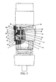
FIG. 3 is a partial sectional view of a preferred embodiment of the present invention when outputting a second-level rotation speed; -
FIG. 4 is a partial sectional view of a preferred embodiment of the present invention when outputting a third-level rotation speed; and- 1. Case; 11. Inner cavity; 12. slot; 13. Elongated hole; 2. Output member; 21. Output gear; 22. First internal gear; 3. Transmission member; 31. First planetary gear set; 32. Gear support; 321. First external groove; 322. Wheel shaft; 33. Second planetary gear set; 34. Second internal gear; 341. Second external groove; 35. Third planetary gear set; 36. Third internal gear; 361. Third external groove; 4. Control member; 41. Control ring gear; 411. Pin hole; 412. Convex Tooth; 413. Internal ring; 42. Pin column; 5. Operation member; 51. Rotary liner; 511. First positioning slot; 512. Second positioning slot; 513. Third positioning slot; 514. Spiral slot; 52. Positioning bead; 53. Spring; 54. Rear cover; 541. Cavity; 6. Input member; 61. First input gear; 62. Second input gear; 63. Third input gear.
- The present invention is further illustrated below with reference to the accompanying drawings and embodiments.
- Referring to
FIG. 1 , a multilevel speed reduction gear box is mainly formed by acase 1, anoutput member 2, a transmission member 3, a control member 4, an operation member 5, and aninput member 6. Theoutput member 2, the transmission member 3, the control member 4, and theinput member 6 are respectively installed within thecase 1. The operation member 5 is rotationally sleeved on thecase 1. The present invention is illustrated in detail below by taking a three-level speed reduction gear as an example. - The
case 1 is a cylindrical shell with aninner cavity 11. A plurality ofelongated holes 13 providing a guiding function along an axial direction is disposed on a wall of thecase 1. An axialkey slot 12 is disposed on an inner wall of theinner cavity 11 opposite to the elongated holes 13. - The
output member 2 is disposed with anoutput gear 21 and a firstinternal gear 22. Theoutput gear 21 may be connected to a rotating shaft of an electric tool directly or connected to the rotating shaft of the electric tool through a speed reduction mechanism. - The transmission member 3 is formed by a first planetary gear set 31, a
gear support 32, a second planetary gear set 33, a secondinternal gear 34, a third planetary gear set 35, and a thirdinternal gear 36. Thegear support 32 is disposed with a firstexternal gear 321 andwheel shafts 322. The first planetary gear set 31, the second planetary gear set 33, and the third planetary gear set 35 are all rotationally disposed on thewheel shafts 322. The number of thewheel shafts 322 may be three, or may also be more than three depending upon the actual demands. However, basically, each planetary gear in all the planetary gear sets 31, 33, and 35 requires a corresponding wheel shaft, so as to be installed thereon. The firstinternal gear 22 is rotationally engaged with the first planetary gear set 31. The secondinternal gear 34 is rotationally engaged with the second planetary gear set 33, and has a secondexternal gear 341 configured on an external part thereof. The thirdinternal gear 36 is rotationally engaged with the third planetary gear set 35, and has a thirdexternal gear 361 configured on an external part thereof. - The control member 4 is formed by a
control ring gear 41 andpin columns 42. Thecontrol ring gear 41 has pin holes 411,keys 412, and aninternal gear 413. The pin holes 411 may be connected to thepin columns 42. Thekeys 412 are slidably fitted with thekey slots 12. Theinternal gear 413 may be respectively engaged with the firstexternal gear 321, the secondexternal gear 341, and the thirdexternal gear 361. - The operation member 5 is formed by a
rotary liner 51, positioningbeads 52, springs 53, and arear cover 54. The operation member 5 is sleeved on thecase 1. Therotary liner 51 has afirst positioning slot 511, asecond positioning slot 512, athird positioning slot 513, andspiral slots 514. The positioningbeads 52 may be respectively engaged with thefirst positioning slot 511, thesecond positioning slot 512, and thethird positioning slot 513. Therear cover 54 has acavity 541 for accommodating thepositioning beads 52 and thesprings 53. Thespiral slots 514 are slidably fitted with thepin columns 42. - The
input member 6 is a triple-coupler gear, in which afirst input gear 61, asecond input gear 62, and athird input gear 63 are rotationally engaged with the first planetary gear set 31, the second planetary gear set 33, and the third planetary gear set 35 respectively. - In a preferred embodiment of the invention, the number of teeth in the
first input gear 61 is 18, the number of teeth in thesecond input gear 62 is 12, the number of teeth in thethird input gear 63 is 15, the number of teeth in the firstinternal gear 22 is 48, the number of teeth in the secondinternal gear 34 is 45, and the number of teeth in the thirdinternal gear 36 is 48. - As shown in
FIGs. 2 ,3 , and4 , after all members are disposed in sequence, thepin columns 42 are inserted in thespiral slots 514 on an inner wall of the operation member 5 after passing through theelongated holes 13 and thecontrol ring gear 41. When an operator rotates therotary liner 51, thespiral slots 514 drive thepin columns 42 to actuate thecontrol ring gear 41 to slide axially. - As shown in
FIG. 2 , when the operator rotates therotary liner 51 to a position where thefirst positioning slot 511 and thepositioning bead 52 are engaged, theinternal gear 413 and the firstexternal gear 321 are engaged. At the same time, the rotation of thegear support 32 is confined. The secondinternal gear 34 and the thirdinternal gear 36 are both in a rotatable status. Thefirst input gear 61 drives the firstinternal gear 22 to rotate in an opposite direction through the first planetary gear set 31. Therefore, theoutput member 2 obtains a first-level rotation speed in a rotation direction opposite to that of theinput member 6. At this time, a transmission ratio between theoutput member 2 and theinput member 6 is about -1:2.67. - As shown in
FIG. 3 , when the operator rotates therotary liner 51 to a position where thesecond positioning slot 512 and thepositioning bead 52 are engaged, theinternal gear 413 and the secondexternal gear 341 are engaged. At the same time, the rotation of the secondinternal gear 34 is confined. Thegear support 32 and the thirdinternal gear 36 are both in a rotatable status. Thesecond input gear 62 drives thegear support 32 to rotate in the same direction through the second planetary gear set 33. As a teeth number ratio between thesecond input gear 62 and the secondinternal gear 34 is smaller than that between thefirst input gear 61 and the firstinternal gear 22, thefirst input gear 61 drives the firstinternal gear 22 to rotate in an opposite direction through the first planetary gear set 31. Therefore, theoutput member 2 obtains a second-level rotation speed in a rotation direction opposite to that of theinput member 6. At this time, a transmission ratio between theoutput member 2 and theinput member 6 is about -1:11.69. - As shown in
FIG. 4 , when the operator rotates therotary liner 51 to a position where thethird positioning slot 513 and thepositioning bead 52 are engaged, theinternal gear 413 and the thirdexternal gear 361 are engaged. At the same time, the rotation of the thirdinternal gear 36 is confined. Thegear support 32 and the secondinternal gear 34 are both in a rotatable status. Thethird input gear 63 drives thegear support 32 to rotate in the same direction through the third planetary gear set 35. As a teeth number ratio between thethird input gear 63 and the thirdinternal gear 36 is smaller than that between thefirst input gear 61 and the firstinternal gear 22, thefirst input gear 61 drives the firstinternal gear 22 to rotate in an opposite direction through the first planetary gear set 31. Therefore, theoutput member 2 obtains a third-level rotation speed in a rotation direction opposite to that of theinput member 6. At this time, a transmission ratio between theoutput member 2 and theinput member 6 is -1:21. - The above disclosure is only intended to describe the invention, rather than limiting the preferred embodiments of the invention, which does not cover all embodiments of the invention as defined in the claims. Persons skilled in the art can make simple variations on the basis of the preferred embodiments of the present invention to obtain some new embodiments. For example, the teeth number of each internal gear or external gear is changed to change a transmission ratio between an output member and an input member. For example, rolling bearings are added between the planetary gears and the wheel shafts to enhance the transmission efficiency. Furthermore, the number of gears in the planetary gear set and the number of coupler gears in the input member and correspondingly the number of the planetary gear sets may be changed, so as to realize the speed reduction at different levels, such that the present invention can be widely adjusted and the user can make various choices.
- A working principle of the present invention is as follows:
- When the control member confines the rotation of the gear support in the transmission member, the input member drives the output member to rotate in an opposite direction through a planetary gear set in the transmission member. Assuming that a teeth number ratio between the input member and the output member is i1 and a rotation speed of the input member is n1, a rotation speed of the output member is n=- n1 i1. i1. When the control member confines the rotation of the internal gear in the transmission member, the input member drives the gear support to rotate in the same direction through a planetary gear set in the transmission member, so that a differential transmission relation is formed between the input member and the output member. Assuming that the teeth number ratio between the input member and the output member is i1, the teeth number ratio between the input member and the internal gear in the transmission member is i2, and the rotation speed of the input member is n1, the rotation speed of the output member is n=n1(i2-i1)/(i2 +1). When i2 <i1, n is negative, that is, the output member rotates in a direction opposite to the input member. When the number of the planetary gear sets in the transmission member is 2 and the number of the internal gear of the transmission member is 1, the output member is enabled to output two levels of rotation speeds in a direction opposite to that of the input member. When the number of the planetary gear sets in the transmission member is 3 and the number of the internal gears of the transmission member is 2, the output member is enabled to output three levels of rotation speeds in a direction opposite to that of the input member. Similarly, by increasing the number of planetary gear sets and internal gears in the transmission member, the output member is enabled to output more levels of rotation speeds in a direction opposite to that of the input member, thereby realizing multilevel speed reduction transmission.
Claims (5)
- A multilevel speed reduction gear box, comprising:a case (1), comprising a plurality of elongated holes (13) and an inner cavity (11), wherein a plurality of axial slots (12) is disposed on an inner wall of the inner cavity (11);a control member (4), comprising a control ring gear (41) and a plurality of control pin columns (42), wherein the control ring gear (41) has an internal groove (413) and a plurality of convex teeth (412), and the plurality of convex teeth (412) are slidably fitted with the axial slots (12) on the inner wall of the inner cavity (11) of the case (1);an operation member (5), being a group of elements (51-54) capable of driving the control member (4) to slide axially and to be positioned selectively;a transmission member (3), formed by a gear support (32), a plurality of planetary gear sets (31, 33, 35) installed on wheel shafts (322) of the gear support (32) and one or more internal gears (34, 36);an input member (6), being a group of coupler gears (61-63) installed on an output shaft of a motor, wherein the coupler gears (61-63) are respectively engaged with the planetary gear sets (31, 33, 35) in the transmission member (3); andan output member (2), comprising an output gear (21),characterized in thatthe output member (2) further comprises an internal gear (22), wherein the internal gear (22) is engaged with a planetary gear set (31) in the transmission member (3);wherein the number of the plurality of planetary gear sets (31, 33, 35) is the same as the number of the internal gears (22, 34, 36) of the transmission member (3) and the output member (2); andwherein the output member (2), the transmission member (3), the control member (4), and the input member (6) are disposed within the inner cavity (11) of the case (1) in sequence, the control member (4) slides non-rotationally in the inner cavity (11) of the case (1), the operation member (5) is installed on an outer wall of the case (1), the control pin columns (42) are respectively connected to the control ring gear (41) and the operation member (5) after passing through the elongated holes (13) of the case (1), and the operation member (5) is adapted to drive the control member (4) to selectively confine the rotation of the gear support (32) in the transmission member (3) or one of the one or more internal gears in the transmission member (3).
- The multilevel speed reduction gear box according to claim 1 wherein when the operation member (5) drives the control member (4) to selectively confine rotation of the gear support (32) or internal gears (34, 36) in the transmission member (3), the output member (2) provides multilevel rotation speed in a rotation direction opposite to that of the input member (6).
- The multilevel speed reduction gear box according to claim 1 or 2, wherein the gear support (32) and the one or more internal gears (34, 36) of the transmission member (3) are configured with the same external groove (341, 361) engaged with the internal groove (413) of the control ring gear (41) in the control member (4).
- The multilevel speed reduction gear box according to any one of claims 1-3, wherein the operation member (5) comprises a rotary liner (51), positioning beads (52), springs (53), and a rear cover (54); a plurality of positioning slots (511-513) and spiral slots (514) is disposed on an inner wall of the rotary liner (51); the positioning beads (52) are engaged with corresponding positioning slots (511-513); the rear cover (54) is provided with a cavity (541) for accommodating the positioning beads (52) and the springs (53); and the spiral slots (514) are slidably fitted with the control pin columns (42) in the control member (4).
- The multilevel speed reduction gear box according to any one of claims 1-4, wherein the output gear (21) in the output member (2) is connected to the output shaft directly or through a secondary speed reduction device.
Applications Claiming Priority (2)
| Application Number | Priority Date | Filing Date | Title |
|---|---|---|---|
| CNU2007200364395U CN201027929Y (en) | 2007-03-26 | 2007-03-26 | Multilevel reduction gear box |
| PCT/CN2008/070474 WO2008116412A1 (en) | 2007-03-26 | 2008-03-11 | A multi-speed reducing gear box |
Publications (3)
| Publication Number | Publication Date |
|---|---|
| EP2161477A1 EP2161477A1 (en) | 2010-03-10 |
| EP2161477A4 EP2161477A4 (en) | 2011-07-13 |
| EP2161477B1 true EP2161477B1 (en) | 2012-08-22 |
Family
ID=39132139
Family Applications (1)
| Application Number | Title | Priority Date | Filing Date |
|---|---|---|---|
| EP08715210A Not-in-force EP2161477B1 (en) | 2007-03-26 | 2008-03-11 | A multi-speed reducing gear box |
Country Status (3)
| Country | Link |
|---|---|
| EP (1) | EP2161477B1 (en) |
| CN (1) | CN201027929Y (en) |
| WO (1) | WO2008116412A1 (en) |
Cited By (2)
| Publication number | Priority date | Publication date | Assignee | Title |
|---|---|---|---|---|
| US9233461B2 (en) | 2012-02-27 | 2016-01-12 | Black & Decker Inc. | Tool having multi-speed compound planetary transmission |
| US12703074B2 (en) | 2019-11-27 | 2026-08-11 | Black & Decker Inc. | Power tool with multispeed transmission |
Families Citing this family (7)
| Publication number | Priority date | Publication date | Assignee | Title |
|---|---|---|---|---|
| CN201027929Y (en) * | 2007-03-26 | 2008-02-27 | 无锡康格工业设计有限公司 | Multilevel reduction gear box |
| CN102712086B (en) * | 2010-01-25 | 2015-08-05 | 株式会社牧田 | Power tool |
| JP5744639B2 (en) * | 2011-06-17 | 2015-07-08 | 株式会社マキタ | Electric tool |
| CN104728402B (en) * | 2015-02-11 | 2017-05-31 | 徐新生 | It is a kind of to can be used for the change gear box of cordless power tool |
| CN205438464U (en) * | 2015-09-21 | 2016-08-10 | 南京德朔实业有限公司 | Power tool |
| CN109249452B (en) * | 2017-07-14 | 2024-04-02 | 惠阳亚伦塑胶电器实业有限公司 | Multifunctional filament cutter |
| US12496682B2 (en) | 2022-08-15 | 2025-12-16 | Techtronic Cordless Gp | Die grinder with an offset gear transmission |
Family Cites Families (7)
| Publication number | Priority date | Publication date | Assignee | Title |
|---|---|---|---|---|
| JPH10151577A (en) * | 1996-11-26 | 1998-06-09 | Matsushita Electric Works Ltd | Rotary tool with transmission |
| DE19902187A1 (en) * | 1998-03-04 | 1999-09-16 | Scintilla Ag | Planetary gearing for use with hand tools e.g. electric screwdrivers etc. |
| JP4132005B2 (en) * | 2000-11-17 | 2008-08-13 | 株式会社マキタ | Electric tool |
| JP4053865B2 (en) * | 2002-11-12 | 2008-02-27 | 株式会社マキタ | Electric tool |
| JP3963323B2 (en) * | 2003-02-07 | 2007-08-22 | 株式会社マキタ | Electric tool |
| US6758783B1 (en) * | 2003-03-22 | 2004-07-06 | Power Network Industry Co., Ltd. | Automatic speed shifting device |
| CN201027929Y (en) * | 2007-03-26 | 2008-02-27 | 无锡康格工业设计有限公司 | Multilevel reduction gear box |
-
2007
- 2007-03-26 CN CNU2007200364395U patent/CN201027929Y/en not_active Expired - Fee Related
-
2008
- 2008-03-11 EP EP08715210A patent/EP2161477B1/en not_active Not-in-force
- 2008-03-11 WO PCT/CN2008/070474 patent/WO2008116412A1/en not_active Ceased
Cited By (6)
| Publication number | Priority date | Publication date | Assignee | Title |
|---|---|---|---|---|
| US9233461B2 (en) | 2012-02-27 | 2016-01-12 | Black & Decker Inc. | Tool having multi-speed compound planetary transmission |
| US9604354B2 (en) | 2012-02-27 | 2017-03-28 | Black & Decker Inc. | Tool having multi-speed compound planetary transmission |
| US10195731B2 (en) | 2012-02-27 | 2019-02-05 | Black & Decker Inc. | Tool having compound planetary transmission |
| US10926398B2 (en) | 2012-02-27 | 2021-02-23 | Black & Decker Inc. | Tool having compound planetary transmission |
| US11738439B2 (en) | 2012-02-27 | 2023-08-29 | Black & Decker Inc. | Power tool with planetary transmission |
| US12703074B2 (en) | 2019-11-27 | 2026-08-11 | Black & Decker Inc. | Power tool with multispeed transmission |
Also Published As
| Publication number | Publication date |
|---|---|
| EP2161477A4 (en) | 2011-07-13 |
| EP2161477A1 (en) | 2010-03-10 |
| WO2008116412A1 (en) | 2008-10-02 |
| CN201027929Y (en) | 2008-02-27 |
Similar Documents
| Publication | Publication Date | Title |
|---|---|---|
| EP2161477A1 (en) | A multi-speed reducing gear box | |
| EP2256368B1 (en) | Speed change mechanism | |
| EP2875906B1 (en) | Multi-speed cycloidal transmission | |
| EP1946895B1 (en) | Power tool | |
| CN101290041B (en) | Eccentric gear mechanism and method for transmitting rotating force thereby | |
| JP4900340B2 (en) | Electric tool | |
| JP2016078618A (en) | Bicycle assist unit | |
| DK177641B1 (en) | A power tool | |
| JP2011016528A (en) | Automatic transmission | |
| US8197379B1 (en) | Transmission mechanism for power tool | |
| CN105636812A (en) | Power transmission device | |
| JP2016120847A (en) | Drive unit for bicycle | |
| KR101675383B1 (en) | Dual one way clutch and transmission having the same | |
| CN112696491A (en) | Electric vehicle drive apparatus | |
| CN104956123B (en) | Transmission | |
| KR101808089B1 (en) | Reducer having a device for reducing rotation speed | |
| CN110067836A (en) | Motor speed change gear | |
| US7455615B2 (en) | Transmission mechanism | |
| CN201989132U (en) | Multi-stage speed change mechanism | |
| JP2002240729A (en) | Vehicle steering system | |
| EP3083156B1 (en) | Spindle lock assembly for power tool | |
| US20100051403A1 (en) | Driving mechanism and wheel assembly for toy car | |
| WO2021044888A1 (en) | Gear speed change device | |
| JP4601454B2 (en) | Geared motor device and toilet seat / toilet lid opening / closing device | |
| JP3171219U (en) | Multi-stage gear changer |
Legal Events
| Date | Code | Title | Description |
|---|---|---|---|
| PUAI | Public reference made under article 153(3) epc to a published international application that has entered the european phase |
Free format text: ORIGINAL CODE: 0009012 |
|
| 17P | Request for examination filed |
Effective date: 20091022 |
|
| AK | Designated contracting states |
Kind code of ref document: A1 Designated state(s): AT BE BG CH CY CZ DE DK EE ES FI FR GB GR HR HU IE IS IT LI LT LU LV MC MT NL NO PL PT RO SE SI SK TR |
|
| AX | Request for extension of the european patent |
Extension state: AL BA MK RS |
|
| DAX | Request for extension of the european patent (deleted) | ||
| A4 | Supplementary search report drawn up and despatched |
Effective date: 20110616 |
|
| REG | Reference to a national code |
Ref country code: DE Ref legal event code: R079 Ref document number: 602008018196 Country of ref document: DE Free format text: PREVIOUS MAIN CLASS: F16H0003440000 Ipc: B25F0005000000 |
|
| GRAP | Despatch of communication of intention to grant a patent |
Free format text: ORIGINAL CODE: EPIDOSNIGR1 |
|
| RIC1 | Information provided on ipc code assigned before grant |
Ipc: F16H 3/66 20060101ALI20120208BHEP Ipc: B25F 5/00 20060101AFI20120208BHEP |
|
| GRAS | Grant fee paid |
Free format text: ORIGINAL CODE: EPIDOSNIGR3 |
|
| GRAA | (expected) grant |
Free format text: ORIGINAL CODE: 0009210 |
|
| AK | Designated contracting states |
Kind code of ref document: B1 Designated state(s): AT BE BG CH CY CZ DE DK EE ES FI FR GB GR HR HU IE IS IT LI LT LU LV MC MT NL NO PL PT RO SE SI SK TR |
|
| REG | Reference to a national code |
Ref country code: GB Ref legal event code: FG4D |
|
| REG | Reference to a national code |
Ref country code: CH Ref legal event code: EP |
|
| REG | Reference to a national code |
Ref country code: IE Ref legal event code: FG4D |
|
| REG | Reference to a national code |
Ref country code: AT Ref legal event code: REF Ref document number: 571701 Country of ref document: AT Kind code of ref document: T Effective date: 20120915 |
|
| REG | Reference to a national code |
Ref country code: DE Ref legal event code: R096 Ref document number: 602008018196 Country of ref document: DE Effective date: 20121018 |
|
| REG | Reference to a national code |
Ref country code: NL Ref legal event code: VDEP Effective date: 20120822 |
|
| REG | Reference to a national code |
Ref country code: AT Ref legal event code: MK05 Ref document number: 571701 Country of ref document: AT Kind code of ref document: T Effective date: 20120822 |
|
| REG | Reference to a national code |
Ref country code: LT Ref legal event code: MG4D Effective date: 20120822 |
|
| PG25 | Lapsed in a contracting state [announced via postgrant information from national office to epo] |
Ref country code: AT Free format text: LAPSE BECAUSE OF FAILURE TO SUBMIT A TRANSLATION OF THE DESCRIPTION OR TO PAY THE FEE WITHIN THE PRESCRIBED TIME-LIMIT Effective date: 20120822 Ref country code: LT Free format text: LAPSE BECAUSE OF FAILURE TO SUBMIT A TRANSLATION OF THE DESCRIPTION OR TO PAY THE FEE WITHIN THE PRESCRIBED TIME-LIMIT Effective date: 20120822 Ref country code: HR Free format text: LAPSE BECAUSE OF FAILURE TO SUBMIT A TRANSLATION OF THE DESCRIPTION OR TO PAY THE FEE WITHIN THE PRESCRIBED TIME-LIMIT Effective date: 20120822 Ref country code: NO Free format text: LAPSE BECAUSE OF FAILURE TO SUBMIT A TRANSLATION OF THE DESCRIPTION OR TO PAY THE FEE WITHIN THE PRESCRIBED TIME-LIMIT Effective date: 20121122 Ref country code: IS Free format text: LAPSE BECAUSE OF FAILURE TO SUBMIT A TRANSLATION OF THE DESCRIPTION OR TO PAY THE FEE WITHIN THE PRESCRIBED TIME-LIMIT Effective date: 20121222 Ref country code: CY Free format text: LAPSE BECAUSE OF FAILURE TO SUBMIT A TRANSLATION OF THE DESCRIPTION OR TO PAY THE FEE WITHIN THE PRESCRIBED TIME-LIMIT Effective date: 20120822 Ref country code: FI Free format text: LAPSE BECAUSE OF FAILURE TO SUBMIT A TRANSLATION OF THE DESCRIPTION OR TO PAY THE FEE WITHIN THE PRESCRIBED TIME-LIMIT Effective date: 20120822 |
|
| PG25 | Lapsed in a contracting state [announced via postgrant information from national office to epo] |
Ref country code: SE Free format text: LAPSE BECAUSE OF FAILURE TO SUBMIT A TRANSLATION OF THE DESCRIPTION OR TO PAY THE FEE WITHIN THE PRESCRIBED TIME-LIMIT Effective date: 20120822 Ref country code: PT Free format text: LAPSE BECAUSE OF FAILURE TO SUBMIT A TRANSLATION OF THE DESCRIPTION OR TO PAY THE FEE WITHIN THE PRESCRIBED TIME-LIMIT Effective date: 20121224 Ref country code: BE Free format text: LAPSE BECAUSE OF FAILURE TO SUBMIT A TRANSLATION OF THE DESCRIPTION OR TO PAY THE FEE WITHIN THE PRESCRIBED TIME-LIMIT Effective date: 20120822 Ref country code: SI Free format text: LAPSE BECAUSE OF FAILURE TO SUBMIT A TRANSLATION OF THE DESCRIPTION OR TO PAY THE FEE WITHIN THE PRESCRIBED TIME-LIMIT Effective date: 20120822 Ref country code: LV Free format text: LAPSE BECAUSE OF FAILURE TO SUBMIT A TRANSLATION OF THE DESCRIPTION OR TO PAY THE FEE WITHIN THE PRESCRIBED TIME-LIMIT Effective date: 20120822 Ref country code: GR Free format text: LAPSE BECAUSE OF FAILURE TO SUBMIT A TRANSLATION OF THE DESCRIPTION OR TO PAY THE FEE WITHIN THE PRESCRIBED TIME-LIMIT Effective date: 20121123 |
|
| PG25 | Lapsed in a contracting state [announced via postgrant information from national office to epo] |
Ref country code: NL Free format text: LAPSE BECAUSE OF FAILURE TO SUBMIT A TRANSLATION OF THE DESCRIPTION OR TO PAY THE FEE WITHIN THE PRESCRIBED TIME-LIMIT Effective date: 20120822 |
|
| PG25 | Lapsed in a contracting state [announced via postgrant information from national office to epo] |
Ref country code: ES Free format text: LAPSE BECAUSE OF FAILURE TO SUBMIT A TRANSLATION OF THE DESCRIPTION OR TO PAY THE FEE WITHIN THE PRESCRIBED TIME-LIMIT Effective date: 20121203 Ref country code: DK Free format text: LAPSE BECAUSE OF FAILURE TO SUBMIT A TRANSLATION OF THE DESCRIPTION OR TO PAY THE FEE WITHIN THE PRESCRIBED TIME-LIMIT Effective date: 20120822 Ref country code: CZ Free format text: LAPSE BECAUSE OF FAILURE TO SUBMIT A TRANSLATION OF THE DESCRIPTION OR TO PAY THE FEE WITHIN THE PRESCRIBED TIME-LIMIT Effective date: 20120822 Ref country code: RO Free format text: LAPSE BECAUSE OF FAILURE TO SUBMIT A TRANSLATION OF THE DESCRIPTION OR TO PAY THE FEE WITHIN THE PRESCRIBED TIME-LIMIT Effective date: 20120822 Ref country code: EE Free format text: LAPSE BECAUSE OF FAILURE TO SUBMIT A TRANSLATION OF THE DESCRIPTION OR TO PAY THE FEE WITHIN THE PRESCRIBED TIME-LIMIT Effective date: 20120822 |
|
| PG25 | Lapsed in a contracting state [announced via postgrant information from national office to epo] |
Ref country code: PL Free format text: LAPSE BECAUSE OF FAILURE TO SUBMIT A TRANSLATION OF THE DESCRIPTION OR TO PAY THE FEE WITHIN THE PRESCRIBED TIME-LIMIT Effective date: 20120822 Ref country code: IT Free format text: LAPSE BECAUSE OF FAILURE TO SUBMIT A TRANSLATION OF THE DESCRIPTION OR TO PAY THE FEE WITHIN THE PRESCRIBED TIME-LIMIT Effective date: 20120822 Ref country code: SK Free format text: LAPSE BECAUSE OF FAILURE TO SUBMIT A TRANSLATION OF THE DESCRIPTION OR TO PAY THE FEE WITHIN THE PRESCRIBED TIME-LIMIT Effective date: 20120822 |
|
| PLBE | No opposition filed within time limit |
Free format text: ORIGINAL CODE: 0009261 |
|
| STAA | Information on the status of an ep patent application or granted ep patent |
Free format text: STATUS: NO OPPOSITION FILED WITHIN TIME LIMIT |
|
| 26N | No opposition filed |
Effective date: 20130523 |
|
| PG25 | Lapsed in a contracting state [announced via postgrant information from national office to epo] |
Ref country code: BG Free format text: LAPSE BECAUSE OF FAILURE TO SUBMIT A TRANSLATION OF THE DESCRIPTION OR TO PAY THE FEE WITHIN THE PRESCRIBED TIME-LIMIT Effective date: 20121122 |
|
| REG | Reference to a national code |
Ref country code: DE Ref legal event code: R097 Ref document number: 602008018196 Country of ref document: DE Effective date: 20130523 |
|
| PG25 | Lapsed in a contracting state [announced via postgrant information from national office to epo] |
Ref country code: MC Free format text: LAPSE BECAUSE OF NON-PAYMENT OF DUE FEES Effective date: 20130331 |
|
| REG | Reference to a national code |
Ref country code: CH Ref legal event code: PL |
|
| REG | Reference to a national code |
Ref country code: DE Ref legal event code: R082 Ref document number: 602008018196 Country of ref document: DE Representative=s name: PATENT- UND RECHTSANWAELTE KRAUS & WEISERT, DE |
|
| REG | Reference to a national code |
Ref country code: FR Ref legal event code: ST Effective date: 20131129 |
|
| REG | Reference to a national code |
Ref country code: IE Ref legal event code: MM4A |
|
| REG | Reference to a national code |
Ref country code: DE Ref legal event code: R082 Ref document number: 602008018196 Country of ref document: DE Representative=s name: PATENT- UND RECHTSANWAELTE KRAUS & WEISERT, DE Effective date: 20131129 Ref country code: DE Ref legal event code: R081 Ref document number: 602008018196 Country of ref document: DE Owner name: WUXI XINJU ELECTRIC TOOLS CO., LTD., CN Free format text: FORMER OWNER: WUXI KANGGE INDUSTRIAL DESIGN CO., LTD., JIANGSU, CN Effective date: 20131129 Ref country code: DE Ref legal event code: R081 Ref document number: 602008018196 Country of ref document: DE Owner name: WUXI XINJU ELECTRIC TOOLS CO., LTD., SHUOFANG, CN Free format text: FORMER OWNER: WUXI KANGGE INDUSTRIAL DESIGN CO., LTD., JIANGSU, CN Effective date: 20131129 Ref country code: DE Ref legal event code: R082 Ref document number: 602008018196 Country of ref document: DE Representative=s name: KRAUS & WEISERT PATENTANWAELTE PARTGMBB, DE Effective date: 20131129 |
|
| REG | Reference to a national code |
Ref country code: GB Ref legal event code: 732E Free format text: REGISTERED BETWEEN 20140102 AND 20140108 |
|
| PG25 | Lapsed in a contracting state [announced via postgrant information from national office to epo] |
Ref country code: FR Free format text: LAPSE BECAUSE OF NON-PAYMENT OF DUE FEES Effective date: 20130402 Ref country code: LI Free format text: LAPSE BECAUSE OF NON-PAYMENT OF DUE FEES Effective date: 20130331 Ref country code: CH Free format text: LAPSE BECAUSE OF NON-PAYMENT OF DUE FEES Effective date: 20130331 Ref country code: IE Free format text: LAPSE BECAUSE OF NON-PAYMENT OF DUE FEES Effective date: 20130311 |
|
| PGFP | Annual fee paid to national office [announced via postgrant information from national office to epo] |
Ref country code: GB Payment date: 20140326 Year of fee payment: 7 |
|
| PG25 | Lapsed in a contracting state [announced via postgrant information from national office to epo] |
Ref country code: MT Free format text: LAPSE BECAUSE OF FAILURE TO SUBMIT A TRANSLATION OF THE DESCRIPTION OR TO PAY THE FEE WITHIN THE PRESCRIBED TIME-LIMIT Effective date: 20120822 |
|
| PGFP | Annual fee paid to national office [announced via postgrant information from national office to epo] |
Ref country code: DE Payment date: 20140407 Year of fee payment: 7 |
|
| PG25 | Lapsed in a contracting state [announced via postgrant information from national office to epo] |
Ref country code: TR Free format text: LAPSE BECAUSE OF FAILURE TO SUBMIT A TRANSLATION OF THE DESCRIPTION OR TO PAY THE FEE WITHIN THE PRESCRIBED TIME-LIMIT Effective date: 20120822 |
|
| PG25 | Lapsed in a contracting state [announced via postgrant information from national office to epo] |
Ref country code: LU Free format text: LAPSE BECAUSE OF NON-PAYMENT OF DUE FEES Effective date: 20130311 Ref country code: HU Free format text: LAPSE BECAUSE OF FAILURE TO SUBMIT A TRANSLATION OF THE DESCRIPTION OR TO PAY THE FEE WITHIN THE PRESCRIBED TIME-LIMIT; INVALID AB INITIO Effective date: 20080311 |
|
| REG | Reference to a national code |
Ref country code: DE Ref legal event code: R119 Ref document number: 602008018196 Country of ref document: DE |
|
| GBPC | Gb: european patent ceased through non-payment of renewal fee |
Effective date: 20150311 |
|
| PG25 | Lapsed in a contracting state [announced via postgrant information from national office to epo] |
Ref country code: GB Free format text: LAPSE BECAUSE OF NON-PAYMENT OF DUE FEES Effective date: 20150311 Ref country code: DE Free format text: LAPSE BECAUSE OF NON-PAYMENT OF DUE FEES Effective date: 20151001 |