EP2161053A1 - Needleless connector with displacement correction - Google Patents
Needleless connector with displacement correction Download PDFInfo
- Publication number
- EP2161053A1 EP2161053A1 EP09251876A EP09251876A EP2161053A1 EP 2161053 A1 EP2161053 A1 EP 2161053A1 EP 09251876 A EP09251876 A EP 09251876A EP 09251876 A EP09251876 A EP 09251876A EP 2161053 A1 EP2161053 A1 EP 2161053A1
- Authority
- EP
- European Patent Office
- Prior art keywords
- gland
- needleless connector
- connector according
- housing
- post
- Prior art date
- Legal status (The legal status is an assumption and is not a legal conclusion. Google has not performed a legal analysis and makes no representation as to the accuracy of the status listed.)
- Withdrawn
Links
- 238000006073 displacement reaction Methods 0.000 title description 13
- 238000012937 correction Methods 0.000 title description 2
- 210000004907 gland Anatomy 0.000 claims abstract description 88
- 230000002787 reinforcement Effects 0.000 claims abstract description 27
- 238000004891 communication Methods 0.000 claims description 8
- 239000012530 fluid Substances 0.000 description 19
- 238000000034 method Methods 0.000 description 9
- 239000000463 material Substances 0.000 description 6
- 238000002347 injection Methods 0.000 description 5
- 239000007924 injection Substances 0.000 description 5
- 230000007704 transition Effects 0.000 description 5
- 238000003780 insertion Methods 0.000 description 4
- 230000037431 insertion Effects 0.000 description 4
- 230000007935 neutral effect Effects 0.000 description 4
- 230000008569 process Effects 0.000 description 4
- 230000000845 anti-microbial effect Effects 0.000 description 3
- 230000008901 benefit Effects 0.000 description 3
- 238000005516 engineering process Methods 0.000 description 3
- 238000011010 flushing procedure Methods 0.000 description 3
- 238000001802 infusion Methods 0.000 description 3
- 230000007246 mechanism Effects 0.000 description 3
- 238000000465 moulding Methods 0.000 description 3
- 150000003839 salts Chemical class 0.000 description 3
- GHXZTYHSJHQHIJ-UHFFFAOYSA-N Chlorhexidine Chemical compound C=1C=C(Cl)C=CC=1NC(N)=NC(N)=NCCCCCCN=C(N)N=C(N)NC1=CC=C(Cl)C=C1 GHXZTYHSJHQHIJ-UHFFFAOYSA-N 0.000 description 2
- LFQSCWFLJHTTHZ-UHFFFAOYSA-N Ethanol Chemical compound CCO LFQSCWFLJHTTHZ-UHFFFAOYSA-N 0.000 description 2
- KFZMGEQAYNKOFK-UHFFFAOYSA-N Isopropanol Chemical compound CC(C)O KFZMGEQAYNKOFK-UHFFFAOYSA-N 0.000 description 2
- 239000008280 blood Substances 0.000 description 2
- 210000004369 blood Anatomy 0.000 description 2
- 229960003260 chlorhexidine Drugs 0.000 description 2
- 238000000576 coating method Methods 0.000 description 2
- 230000006870 function Effects 0.000 description 2
- 238000001990 intravenous administration Methods 0.000 description 2
- 238000005461 lubrication Methods 0.000 description 2
- 238000002156 mixing Methods 0.000 description 2
- YGSDEFSMJLZEOE-UHFFFAOYSA-N salicylic acid Chemical compound OC(=O)C1=CC=CC=C1O YGSDEFSMJLZEOE-UHFFFAOYSA-N 0.000 description 2
- SQGYOTSLMSWVJD-UHFFFAOYSA-N silver(1+) nitrate Chemical compound [Ag+].[O-]N(=O)=O SQGYOTSLMSWVJD-UHFFFAOYSA-N 0.000 description 2
- 238000002560 therapeutic procedure Methods 0.000 description 2
- JKFYKCYQEWQPTM-UHFFFAOYSA-N 2-azaniumyl-2-(4-fluorophenyl)acetate Chemical compound OC(=O)C(N)C1=CC=C(F)C=C1 JKFYKCYQEWQPTM-UHFFFAOYSA-N 0.000 description 1
- VPWNQTHUCYMVMZ-UHFFFAOYSA-N 4,4'-sulfonyldiphenol Chemical class C1=CC(O)=CC=C1S(=O)(=O)C1=CC=C(O)C=C1 VPWNQTHUCYMVMZ-UHFFFAOYSA-N 0.000 description 1
- 229940123208 Biguanide Drugs 0.000 description 1
- 229930185605 Bisphenol Natural products 0.000 description 1
- WJLVQTJZDCGNJN-UHFFFAOYSA-N Chlorhexidine hydrochloride Chemical compound Cl.Cl.C=1C=C(Cl)C=CC=1NC(N)=NC(N)=NCCCCCCN=C(N)N=C(N)NC1=CC=C(Cl)C=C1 WJLVQTJZDCGNJN-UHFFFAOYSA-N 0.000 description 1
- ZAMOUSCENKQFHK-UHFFFAOYSA-N Chlorine atom Chemical compound [Cl] ZAMOUSCENKQFHK-UHFFFAOYSA-N 0.000 description 1
- 208000035473 Communicable disease Diseases 0.000 description 1
- RYGMFSIKBFXOCR-UHFFFAOYSA-N Copper Chemical compound [Cu] RYGMFSIKBFXOCR-UHFFFAOYSA-N 0.000 description 1
- 206010069803 Injury associated with device Diseases 0.000 description 1
- 229910021612 Silver iodide Inorganic materials 0.000 description 1
- QAOWNCQODCNURD-UHFFFAOYSA-L Sulfate Chemical compound [O-]S([O-])(=O)=O QAOWNCQODCNURD-UHFFFAOYSA-L 0.000 description 1
- XEFQLINVKFYRCS-UHFFFAOYSA-N Triclosan Chemical compound OC1=CC(Cl)=CC=C1OC1=CC=C(Cl)C=C1Cl XEFQLINVKFYRCS-UHFFFAOYSA-N 0.000 description 1
- 150000001251 acridines Chemical class 0.000 description 1
- 150000001298 alcohols Chemical class 0.000 description 1
- 239000004599 antimicrobial Substances 0.000 description 1
- 229940027983 antiseptic and disinfectant quaternary ammonium compound Drugs 0.000 description 1
- 229960000686 benzalkonium chloride Drugs 0.000 description 1
- CADWTSSKOVRVJC-UHFFFAOYSA-N benzyl(dimethyl)azanium;chloride Chemical compound [Cl-].C[NH+](C)CC1=CC=CC=C1 CADWTSSKOVRVJC-UHFFFAOYSA-N 0.000 description 1
- 150000004283 biguanides Chemical class 0.000 description 1
- KGBXLFKZBHKPEV-UHFFFAOYSA-N boric acid Chemical compound OB(O)O KGBXLFKZBHKPEV-UHFFFAOYSA-N 0.000 description 1
- 239000004327 boric acid Substances 0.000 description 1
- 230000008859 change Effects 0.000 description 1
- 239000003795 chemical substances by application Substances 0.000 description 1
- 229960002152 chlorhexidine acetate Drugs 0.000 description 1
- YZIYKJHYYHPJIB-UUPCJSQJSA-N chlorhexidine gluconate Chemical compound OC[C@@H](O)[C@@H](O)[C@H](O)[C@@H](O)C(O)=O.OC[C@@H](O)[C@@H](O)[C@H](O)[C@@H](O)C(O)=O.C1=CC(Cl)=CC=C1NC(=N)NC(=N)NCCCCCCNC(=N)NC(=N)NC1=CC=C(Cl)C=C1 YZIYKJHYYHPJIB-UUPCJSQJSA-N 0.000 description 1
- 229960003333 chlorhexidine gluconate Drugs 0.000 description 1
- 229960004504 chlorhexidine hydrochloride Drugs 0.000 description 1
- 229910052801 chlorine Inorganic materials 0.000 description 1
- 239000000460 chlorine Substances 0.000 description 1
- 239000011248 coating agent Substances 0.000 description 1
- 230000006835 compression Effects 0.000 description 1
- 238000007906 compression Methods 0.000 description 1
- 238000007796 conventional method Methods 0.000 description 1
- 229910052802 copper Inorganic materials 0.000 description 1
- 239000010949 copper Substances 0.000 description 1
- 239000013078 crystal Substances 0.000 description 1
- 239000000645 desinfectant Substances 0.000 description 1
- 239000000975 dye Substances 0.000 description 1
- 230000000694 effects Effects 0.000 description 1
- 229910052736 halogen Inorganic materials 0.000 description 1
- 150000002367 halogens Chemical class 0.000 description 1
- 238000007373 indentation Methods 0.000 description 1
- 150000002497 iodine compounds Chemical class 0.000 description 1
- 238000004519 manufacturing process Methods 0.000 description 1
- 239000000203 mixture Substances 0.000 description 1
- 238000012986 modification Methods 0.000 description 1
- 230000004048 modification Effects 0.000 description 1
- FJKROLUGYXJWQN-UHFFFAOYSA-N papa-hydroxy-benzoic acid Natural products OC(=O)C1=CC=C(O)C=C1 FJKROLUGYXJWQN-UHFFFAOYSA-N 0.000 description 1
- 230000002093 peripheral effect Effects 0.000 description 1
- 229920001296 polysiloxane Polymers 0.000 description 1
- 230000036316 preload Effects 0.000 description 1
- MCSINKKTEDDPNK-UHFFFAOYSA-N propyl propionate Chemical compound CCCOC(=O)CC MCSINKKTEDDPNK-UHFFFAOYSA-N 0.000 description 1
- 150000003856 quaternary ammonium compounds Chemical class 0.000 description 1
- 238000010992 reflux Methods 0.000 description 1
- 230000004044 response Effects 0.000 description 1
- 229960004889 salicylic acid Drugs 0.000 description 1
- 229910052709 silver Inorganic materials 0.000 description 1
- 239000004332 silver Substances 0.000 description 1
- CQLFBEKRDQMJLZ-UHFFFAOYSA-M silver acetate Chemical compound [Ag+].CC([O-])=O CQLFBEKRDQMJLZ-UHFFFAOYSA-M 0.000 description 1
- 229940071536 silver acetate Drugs 0.000 description 1
- 229940045105 silver iodide Drugs 0.000 description 1
- 229910001961 silver nitrate Inorganic materials 0.000 description 1
- 229960001516 silver nitrate Drugs 0.000 description 1
- 229960003600 silver sulfadiazine Drugs 0.000 description 1
- UEJSSZHHYBHCEL-UHFFFAOYSA-N silver(1+) sulfadiazinate Chemical compound [Ag+].C1=CC(N)=CC=C1S(=O)(=O)[N-]C1=NC=CC=N1 UEJSSZHHYBHCEL-UHFFFAOYSA-N 0.000 description 1
- 239000000126 substance Substances 0.000 description 1
- -1 triclosan Chemical class 0.000 description 1
- 229960003500 triclosan Drugs 0.000 description 1
- 238000003466 welding Methods 0.000 description 1
Images





Classifications
-
- A—HUMAN NECESSITIES
- A61—MEDICAL OR VETERINARY SCIENCE; HYGIENE
- A61M—DEVICES FOR INTRODUCING MEDIA INTO, OR ONTO, THE BODY; DEVICES FOR TRANSDUCING BODY MEDIA OR FOR TAKING MEDIA FROM THE BODY; DEVICES FOR PRODUCING OR ENDING SLEEP OR STUPOR
- A61M39/00—Tubes, tube connectors, tube couplings, valves, access sites or the like, specially adapted for medical use
- A61M39/22—Valves or arrangement of valves
- A61M39/26—Valves closing automatically on disconnecting the line and opening on reconnection thereof
-
- A—HUMAN NECESSITIES
- A61—MEDICAL OR VETERINARY SCIENCE; HYGIENE
- A61M—DEVICES FOR INTRODUCING MEDIA INTO, OR ONTO, THE BODY; DEVICES FOR TRANSDUCING BODY MEDIA OR FOR TAKING MEDIA FROM THE BODY; DEVICES FOR PRODUCING OR ENDING SLEEP OR STUPOR
- A61M39/00—Tubes, tube connectors, tube couplings, valves, access sites or the like, specially adapted for medical use
- A61M39/22—Valves or arrangement of valves
- A61M39/26—Valves closing automatically on disconnecting the line and opening on reconnection thereof
- A61M2039/266—Valves closing automatically on disconnecting the line and opening on reconnection thereof where the valve comprises venting channels, e.g. to insure better connection, to help decreasing the fluid space upon disconnection, or to help the fluid space to remain the same during disconnection
Definitions
- This patent is directed to a needleless connector, and, in particular, to a needleless connector with a mechanism for displacement correction.
- Needleless connectors have come into widespread use in intravenous (I.V.) administration sets. Needleless connectors replace more traditional technologies, wherein a needle is used to puncture an elastomeric diaphragm or septum.
- I.V. intravenous
- Needleless connectors replace more traditional technologies, wherein a needle is used to puncture an elastomeric diaphragm or septum.
- the use of needles and other pointed instruments presents hazards to equipment, patients and healthcare personnel. For example, accidental needle sticks may permit infectious diseases to be transferred from the patient to the healthcare worker.
- certain needleless connectors may be subject to retrograde flow. That is, when a syringe, blunt cannula or other instrument is inserted into the connector, a volume of fluid is displaced out of the connector and associated set into the patient. This is referred to antegrade flow. However, when the instrument is withdrawn, a similar volume may be drawn into the I.V. set components or the connector from the patient. This is referred to as retrograde flow or reflux.
- a needleless connector in one aspect, includes a housing having an inlet and an outlet, a valve disposed in the housing to control flow between the inlet and the outlet, and a gland disposed in the housing between the inlet and the outlet.
- the gland has a deformable wall defining a space, and at least one reinforcement attached to the deformable wall within the space.
- Fig. 1 is a perspective view of a needleless connector according to the present disclosure
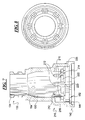
- Fig. 2 is a cross-sectional view of the needleless connector of Fig. 1 taken along line 2-2;
- Fig. 3 is a cross-sectional view of the needleless connector of Fig. 1 taken along line 3-3;
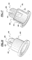
- Fig. 4 is a perspective view of a septum to be used in the needleless connector of Fig. 1 ;
- Fig. 5 is a perspective view of an alternative septum
- Fig. 6 is a perspective view of a further alternative septum
- Fig. 7 is a cross-sectional view of an inlet section to be used in the needleless connector of Fig. 1 ;
- Fig. 8 is an end view of the inlet section of Fig. 7 ;
- Fig. 9 is a perspective view of an outlet section to be used in the needleless connector of Fig. 1 ;
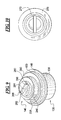
- Fig. 10 is an end view of a gland to be used in the needleless connector of Fig. 1 ;
- Fig. 11 is a cross-sectional view of the gland taken along line 11-11 in Fig 10 ;
- Fig. 12 is a cross-sectional view of the gland taken along line 12-12 in Fig. 10 ;
- Fig. 13 is an end view of an alternative gland to be used in the needleless connector such as the connector illustrated in Fig. 1 ;
- Fig. 14 is a cross-sectional view of the gland taken along line 14-14 in Fig. 13 ;
- Fig. 15 is a cross-sectional view of the gland taken along line 15-15 in Fig. 13 ;
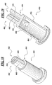
- Fig. 16 is a perspective view of a further alternative gland to be used in needleless connectors such as the connector illustrated in Fig. 1 ;
- Fig. 17 is a cross-sectional view of the gland taken along the line 17-17 in Fig. 16 ;
- Fig. 18 is a perspective view of another alternative gland to be used in needleless connectors such as the connector illustrated in Fig. 1 ;
- Fig. 19 is a cross-sectional view of the gland taken along the line 19-19 in Fig. 18 ;
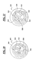
- Fig. 20 is a plan view of an alternative gland with a variant in regard to the groove in the post of the gland, the gland to be used with needleless connectors such as the connector illustrated in Fig. 1 ;
- Fig. 21 is a plan view of a further alternative gland with a variant in regard to the groove in the post of the gland, the gland to be used with needleless connectors such as the connector illustrated in Fig. 1 ;
- Fig. 22 is a cross-sectional view of an alternative needleless connector similar to that illustrated above.
- Embodiments of a needleless connector according to the present disclosure are discussed herein.
- a convention has been used where the direction towards the top of the page is generally referred to as “distal,” and the direction towards the bottom of the page is generally referred to as “proximal.” It will be recognized that use of this convention is intended to simplify reference to the features as illustrated, not to limit the features to a particular orientation in use, for example.
- Fig. 1 illustrates an embodiment of a needleless connector 100.
- the connector 100 may be used to provide multiple fluid connections with a Luer syringe, a blunt cannula or other instrument.
- the connector 100 may be attached to a conduit in fluid communication with a patient.
- the conduit may be a peripheral catheter, medical tubing (such as may be used in an intravenous (I.V.) administration set), etc. to form a passageway in fluid communication with the patient for the flow of fluid to the patient.
- the connector 100 may be used in or connected to other items as well, for example, a vial or vial adapter.
- the needleless connector 100 includes a housing 110, a valve 112, and a gland 114.
- the valve 112 and the gland 114 are disposed in the housing 110.
- the valve 112 controls the flow of fluid through the housing 110.
- the gland 114 is intended to minimize retrograde flow into the housing 110 by providing a positive pressure or positive displacement response according to certain embodiments, although neutral (or even negative) displacement may be possible according to other embodiments.
- the housing 110 has an inlet 120, an outlet 122 and a vent 124.
- the housing 110 may include an inlet section 130 with having a distal end 132 with an opening 134 formed therein, the opening 134 defining the inlet 120.
- the housing 110 may also include an outlet section 136 having a proximal end 138 with an opening 140 formed therein, the outlet section 136 defining the outlet 122.
- the inlet section 130 is attached to the outlet section 136 with the valve 112 and the gland 114 disposed therein.
- the inlet section 130 has a proximal end 142 with an opening 144 formed therein to accept a portion of the outlet section 136 (see Figs. 3 and 7 ).
- the outlet section 136 has a distal end 146 and an outer surface 148 defining a shoulder 150 at the distal end 146 (see Figs. 3 and 9 ).
- the distal end 146 of the outlet section 136 is disposed within the opening 144 in the proximal end 142 of the inlet section 130, with a shoulder 152 of the inlet section 130 abutting the shoulder 150 of the outlet section 136.
- the shoulder 152 may be attached to the shoulder 150 through conventional methods, such as ultrasonic welding.
- the valve 112 that controls the flow of fluids between the inlet 120 and the outlet 122 is in the form of an overmolded septum, which may be elastic and resilient and made of silicone, for example.
- the septum may be molded from a material having a single durometer value, or, alternatively, may be molded in layers with each layer having a different durometer value.
- other valve types may be used, including septums that have not been overmolded, for example.
- the valve illustrated in the drawings is thus intended to be illustrative and non-limiting.
- the illustrated valve 112 includes a first wall 160 that is disposed across the opening 134 in the inlet section 130, and a second wall 162 that depends away from the first wall 160 along a passage 164 formed in the inlet section 130.
- the first wall 160 is disc-shaped, while the second wall 162 is cylindrical.
- the first wall 160 of the septum 112 has a slit 166 (see Figs. 1 and 3 ) that extends either partially or entirely through the first wall 160; if the slit 166 does not extend completely through the septum 112, disposing an instrument through the slit 166 should force the slit 166 to extend completely through the septum 112.
- the slit 166 may be cut using blades that may vary the inner geometry of the slit 166, so that the slit 166 may be trapezoidal instead of rectangular when viewed in a cross-sectional plane. Further, various preloads may be placed on the septum 112 during the slitting process to change the inner geometry.
- the first wall 160 is stretched downward into the housing 110 when an instrument is disposed into the slit 166 to seal against leakage at an interface between the instrument and the septum 112 before, during and after extension of the instrument through the slit 166.
- the septum 112 may be lubricated to facilitate insertion of the instrument into the septum 112, which lubrication may be applied while forming the slit 166 or by other methods such as incorporating the lubrication into the septum material or by applying lubricous coatings to an outer surface 168 of the septum 112.
- the slit 166 elastically retracts upon removal of the instrument.
- an inner surface 170 of the septum 112 has lips 172 that depend from the inner surface 170 on either side of the slit 166.
- the septum 112 includes facets 174 depending from the lips 172 on opposite sides of the lips 172. The cooperation of the lips 172, as reinforced by the facets 174, reduces the tendency of the slit to open.
- the facets 174 have an angled surface 176.
- the angled surfaces 176 have an edge 182 along which they meet the planar, opposed surfaces 184, 186 of the lips 172.
- These planar, opposed surfaces 184, 186 are parallel to a longitudinal axis 188 of the connector 100 (see Fig. 3 ) between the interfaces with the edges 182 of the angled surfaces 176 and a proximal end 190 of the lips 172.
- the planar surfaces 184, 186 converge in the direction of the longitudinal axis 188 to a line 192 at runs between first and second ends 194, 196. As illustrated, neither the line 192 nor the section of the surfaces 184, 186 that leads up to the line 192 is in contact with structures of the gland 114.
- the features that improve the ability of the slit 166 to remain closed may also have an undesirable effect on the amount of force required by the user to insert an instrument, whether Luer syringe, blunt cannula, etc., into the slit 166.
- additional features may be added to the septum 112, which also may best be seen in Fig. 4 .
- the first and second ends 194, 196 of the lips 172 each have a rounded depression 198, 200 formed therein.
- the rounded depressions 198, 200 each define a region of reduced cross-section, thereby reducing the force required to open the slit 166 through the insertion of an instrument into the slit 166.
- an embodiment of a needleless connector 100 even one using an overmolded slit septum as the valve 112, include all of the features illustrated in Figs. 2-4 .
- the rounded depressions 198, 200 at the ends of the lips 172 may be removed, as illustrated in Fig. 5 .
- the facets 174 that support and reinforce the lips 172 may also be removed, as illustrated in Fig. 6 .
- the septum 112 illustrated in Figs. 2-4 is only one such embodiment that may be used with the needleless connector 100 according to the present disclosure.
- the passage 164 widens in cross-sectional area as it moves along from the distal end 132 to the proximal end 142, as best seen in Figs. 7 and 8 .
- the single passage is divided into a plurality of passages 212 through the presence of a plurality of dividers 214; while eight passages 212 are illustrated, a greater or a lesser number of passages 212 may be present in a given embodiment.
- Each divider 214 has spaced side surfaces 216, 218, the side surfaces 216, 218 of adjacent dividers 214 defining one of the plurality of passages 212.
- Each divider 214 also includes a stepped region 220 that defines a shoulder 222, the purpose of which is explained in greater detail below.
- this passage 224 has an annular shape.
- the annular passage 224 is defined by a surface 226 of the inlet section 130 and an opposing surface 228 formed at the distal end 146 of the outlet section 136.
- the distal end 146 has at least one opening 240 formed in the surface 228 in fluid communication with the annular passage 224. As illustrated, two openings 240 are provided at opposite ends 242, 244 of a cross passage 246 that passes through the distal end 146 of the outlet section 136. It will be recognized that a single cross passage 246 may be advantageous in terms of its fabrication using a molding process, but it will also be recognized that the outlet section 136 is not restricted to such an arrangement or number of openings and passages.
- the cross passage 246 connects to a passage 248 disposed along a longitudinal axis of the outlet section 136, which passage 248 has at its proximal end 250 the opening 140 that defines the outlet 122.
- the axial passage 248 is orthogonal to the cross passage 246, forming a T-shaped intersection, although it will be recognized that the passages 246, 248 could meet at some other angle as well.
- the axial passage 248 may be defined by a lumen 252 of a projection 254 from the outlet section 136.
- the projection 254 is in the form of a Luer tip, and a skirt 256 is arranged coaxially with the projection 254, and has a threaded region 258 formed on an inner surface 260 thereof. Consequently, the illustrated embodiment may be used as a Luer lock. However, the present disclosure is not limited to an outlet section 136 with such an arrangement; this is simply one embodiment according to the present disclosure.
- the projection 254 may be formed as a slip Luer by omitting the threaded region 258.
- the connector 100 could instead be formed as the injection arm of a Y-site or Y-set or as an inlet on a stopcock or manifold, or formed integrally with a catheter. In any event, the housing 110 may have indentations that facilitate gripping of the connector 100.
- the gland 114 disposed in the passage 164 prior to the transition region 210 is the gland 114.
- the gland 114 is thus disposed in the housing 110 between the inlet 120 and the outlet 122.
- the gland 114 functions to limit, and preferably to prevent, a retrograde flow of fluid through the outlet 122 into the housing 110 when a Luer syringe, blunt cannula, or other instrument is inserted into and then withdrawn from the connector 100.
- the gland 114 may provide a positive pressure to eject fluid from the outlet 122 upon withdrawal of the instrument from the connector 100.
- the gland 114 has a deformable wall 270 defining a space 272.
- the deformable wall 270 is a cup-shaped wall having a closed distal end 274 and an open proximal end 276.
- the wall 270 also includes a flange 278 disposed about the periphery of the open proximal end 276.
- the space 272 defined by the deformable wall 270 is in communication with the at least one vent 124 formed in the housing 110 via the open proximal end 276. As illustrated, there are two vents 124, each vent 124 defined by a passage 280, 282 formed in the outlet section 136. It will be recognized that a greater or a lesser number of vents 124 may be included, and the vents 124 may be defined by structures other than the outlet section 136 as identified in the illustrated embodiment.
- the outlet section 136 may include a trough 284 having a first end 286 and a second end 288.
- Each passage 280, 282 is connected to one of the first end 286 or the second end 288 of the trough 284.
- a trough 284 is an optional feature, it may be an advantageous feature, in that the trough 284 provides a larger opening for access to the two passages 280, 282 that define the vents 124, thereby limiting the chances that the gland 114 will restrict access to the vents 124 to prevent escape of air from the space 272.
- vents 124 spaced at opposite ends 286, 288 of the trough 284
- the number of vents and their placement i.e., two vents 124 spaced at opposite ends 286, 288 of the trough 284
- the gland 114 is maintained in place within the housing 110 with the proximal open end 276 in communication with the vents 124 at the distal end 146 of the outlet section 136 through cooperation of the inlet section 130, the outlet section 136, and the gland 114.
- the dividers 214 that are formed in the transition region 210 of the inlet section 130 have a stepped shoulder 222. This shoulder 222 faces a surface 290 at the distal end 146 of the outlet section 136 (compare Figs. 7 and 9 ).
- the flange 278 of the gland 114 is disposed between the opposing surfaces of the inlet section 130 and the outlet section 136 to attach the gland 114 to the housing 110.
- the number of dividers 214 may be influenced by a desired flow rate, but also the need to maintain a sufficient amount of surface in the shoulder 222 so as to cooperate with the surface 290 to maintain the gland 114 in place.
- the gland 114 is deformable to limit retrograde flow into the connector 100.
- the gland 114 has at least one reinforcement 300 attached to the deformable wall 270 within the space 272.
- the at least one reinforcement 300 causes the deformable wall 270 to collapse in a preferred fashion, with collapse occurring inwardly near the center of the gland 114, similar to a bellows or accordion.
- the distal end 274 of the cup-shaped wall 270 defines an internal shoulder 302, and the at least one reinforcement 300 is attached to the deformable wall 270 at the internal shoulder 302.
- the reinforcement 300 is a triangular tab attached across the internal shoulder 302, with a first end 304 formed integrally with a transverse surface 306 of the wall 270 and a second end 308 formed integrally with a lateral surface 310 of the wall 270.
- the shape and relative dimensions of the reinforcements 300 as illustrated are only one embodiment according to the present disclosure. It will also be recognized that other changes to the gland 114 may be made in conjunction with the reinforcements 300 to vary the collapsing profile and/or collapsed shape of the gland 114.
- the height of the wall 270 may vary the collapsing profile, as may the thickness of the wall 270, which may vary between proximal and distal ends.
- the wall 270 may be molded in layers, each layer having a different durometer value, to vary the collapsing profile.
- the collapsing profiles and/or collapsed shape may influence not only the displacement provided (e.g., positive, neutral or negative), but the profiles may influence the flow of fluid about the gland 114.
- the shape, the size or the placement of the reinforcement 300 or the height or the thickness of the wall 270, while maintaining the cross-section of the gland 114 a family of glands may be produced that permit use of the connector 100 in pediatric as well as adult settings.
- the gland 114 also includes features that guide the contact between a Luer syringe, blunt cannula or other instrument and the gland 114.
- the gland 114 includes a post 312 that depends from the wall 270 toward the septum 112, the post 312 having a proximal end 314 attached to the wall 270 and a free distal end 316. See Figs. 2 and 3 , as well as Figs. 10-12 .
- the post 312 has a groove 318 that extends from the distal end 316 to the proximal end 314 of the post 312, dividing the post 312 into two sections 320, 322.
- the groove 318 assists in maintaining an open path for passage of fluids from the instrument into the connector 100.
- the distal end 316 has a concave depression 324 which assists in centering the instrument on the gland 114.
- the at least one reinforcement 300 is attached to the deformable wall 270 along an axis transverse to the groove 318.
- two reinforcements 300 are shown, the two reinforcements 300 attached to the deformable wall 270 along an axis transverse to the groove 318.
- this is not an exclusive orientation of the reinforcements 300 relative to the groove 318, but one such embodiment.
- Figs. 13-15 illustrate an alternative embodiment of a gland 400 for use in a needleless connector similar to that in Figs. 1-9 .
- the gland 400 is substantially structurally similar to that illustrated in Figs. 10-12 .
- the gland 400 has a cup-shaped deformable wall 402 with a closed distal end 404 and an open proximal end 406, a flange 408 being disposed about the open proximal end 406.
- the gland 400 also has a post 410 with a groove 412 formed therein between a distal end 414 and a proximal end 416 such that the gland 400 has separate sections 418, 420.
- the gland 400 has a pair of reinforcements 422 disposed in a space 424 defined by the cup-shaped wall 402, the reinforcements 422 being disposed along an axis transverse to the axis along which the groove 412 is formed.
- the gland 400 of Figs. 13-15 differs from the gland 114 of Figs. 10-12 relates to the distal end 414 of the post 410.
- the distal end 404 of the gland 400 does not have a rim or edge that bounds a concave depression 426 in the distal end 404. Instead, the depression 426 of the distal end 404 extends to the periphery of the post 410.
- FIG. 16 and 17 Another embodiment of a gland 450 that may be used with a needleless connector, such as is illustrated in Figs. 1-9 , is illustrated in Figs. 16 and 17 . Similar to the embodiments in Figs. 10-12 and 13-15 , the gland 450 of Figs. 16 and 17 has a cup-shaped wall 452 with reinforcements 454 disposed in a space 456 defined by the cup-shaped wall 452. The gland 450 also has a post 458 that depends from a distal end 460 of the cup-shaped wall 452, the post 458 being separated by a groove 462 into halves.
- the post 458 does not have a distal end 464 that is concave, but rather a distal end 464 that is convex, which shape is believed to limit the possibilities that an outlet of any instrument inserted into the septum will become occluded through cooperation with the post 458.
- the reinforcements 454 are disposed along an axis that is parallel to, rather than transverse to, the axis of the groove 462.
- FIG. 18 A still further embodiment of a gland 480 that may be used with a needleless connector, such as is illustrated in Figs. 1-9 , is illustrated in Figs. 18 and 19 .
- This embodiment is most closely similar to that illustrated in Figs. 16 and 17 .
- the gland 480 includes a cup-shaped wall 482 that defines a space 484 with reinforcements 486 disposed therein, and a post 488 with a groove 490 formed from a distal end 492 to a proximal end 494 to divide the post 488 into two sections 496, 498.
- the reinforcements 486 are disposed along an axis parallel to an axis of the groove 490.
- the groove 490 does not simply extend from the distal end 492 to the proximal end 494, so as to form a rectangular parallelepiped space between opposing surfaces on the two sections 496, 498 of the post 488. Instead, the groove 490 has a cylindrical space formed along a longitudinal axis of the gland 480. The groove 490 thus defines a space that is the union of a rectangular parallelepiped and a cylinder.
- the cylindrical space will limit the chances that the distal end 492 of the post 488 will prevent passage of fluid from an instrument disposed in a connector in which the gland 480 is used, which may be particularly important as the distal end 492 of the post 488 is planar, instead of concave or convex.
- a gland 500 includes a post 502 with a groove 504.
- the groove 504 has a center 506 with outwardly extending arms 508, 510.
- the arms 508, 510 are curved, such that the groove 504 appears to be S-shaped when viewed from the end, as in Fig. 20 .
- a gland 520 includes a post 522 with a groove 524.
- the groove 524 also has a center 526 with outwardly extending arms 528, 530, 532, 534.
- the arms 528, 530, 532, 534 are straight, such that the groove 524 appears to be X-shaped when viewed from the end, as in Fig. 21 .
- Such geometries may assist in the mixing of fluids during injection, or the flushing of the connector and associated catheter after injection, as may other geometries, such as V-shaped or inverted V-shaped grooves.
- the centers 506, 526 of the grooves 504, 524 may have an enlarged cylindrical space to potential improve fluid flow.
- the groove may be disposed so that the groove is not aligned with the axis of the post, such non-alignment potentially having a similar benefit relative to the mixing of fluids during injection or the flushing of the connector and catheter after injection.
- the groove does not have a consistent cross-section axially between distal and proximal ends. That is, as illustrated in the embodiments above, the groove has the same cross-section in all planes orthogonal to the axis of the post.
- FIG. 22 A further embodiment of a needleless connector 550 is illustrated in Fig. 22 , the connector 550 being similar in many respects to the connector 100 discussed above relative to Figs. 1-4 and 7-12 . That is, the connector 550 includes a housing 552, a valve 554, and a gland 556. The valve 554 and the gland 556 are disposed in the housing 552. The valve 554 controls the flow of the fluid through the housing 552 between an inlet 558 and an outlet 560, which inlet 558 and outlet 560 are formed in different sections 562, 564 of the housing 552.
- the gland 556 has a flange 566 that is disposed between surfaces of the sections 562, 564 to hold the gland 556 in position.
- the gland 556 also includes a wall 568 that defines a space 570 in which at least one reinforcement 572 is disposed.
- the space 570 is not in communication with a vent. Instead, the space 570 is closed by a surface 574 of the section 564 of the housing 552.
- the fluid e.g., air
- the air may be compressed into a smaller space, with the wall 568 of the gland 556 collapsing as before, guided by the presence of the reinforcement 572.
- the embodiment according to Fig. 22 may not provide a positive pressure or displacement as the connector 100, but it may instead provide a clinically neutral displacement. Even in this instance, the presence of the reinforcement 572 within the space 570 is believed to advantageously guide the deformation of the gland 556.
- needleless connector and gland may provide one or more of the following advantages relative to conventional needleless connectors, even those that include mechanisms for limiting retrograde flow.
- the positioning of the reinforcements inside the space defined by the gland provides a more consistent deformation than in other devices used to provide positive pressure or positive displacement, or neutral displacement for that matter.
- the shape of the end of the gland provides for more consistent application of force by the instrument (Luer syringe, cannula, etc.) to the gland, while maintaining adequate flow.
- the antimicrobial material may include chemical disinfectants, for example, alcohols, such as isopropanol and ethanol.
- Biguanides may also be used, including chlorhexidine and its salts (e.g. chlorhexidine acetate, chlorhexidine gluconate, chlorhexidine hydrochloride and chlorhexidine sulfate).
- chlorhexidine and its salts e.g. chlorhexidine acetate, chlorhexidine gluconate, chlorhexidine hydrochloride and chlorhexidine sulfate.
- Further examples include, bisphenols, including triclosan, and halogen-releasing agents, including chlorine and iodine compounds.
- Silver and its salts e.g.
- silver acetate, silver iodide, silver nitrate, silver sulfadiazine may be included, as may copper and its salts.
- quaternary ammonium compounds including benzalkonium chloride, may be used.
- antimicrobial dyes including acridines and crystal violet, boric acid, salicylic acid and N-halamines.
Landscapes
- Health & Medical Sciences (AREA)
- Heart & Thoracic Surgery (AREA)
- Pulmonology (AREA)
- Engineering & Computer Science (AREA)
- Anesthesiology (AREA)
- Biomedical Technology (AREA)
- Hematology (AREA)
- Life Sciences & Earth Sciences (AREA)
- Animal Behavior & Ethology (AREA)
- General Health & Medical Sciences (AREA)
- Public Health (AREA)
- Veterinary Medicine (AREA)
- Infusion, Injection, And Reservoir Apparatuses (AREA)
Abstract
Description
- This patent is directed to a needleless connector, and, in particular, to a needleless connector with a mechanism for displacement correction.
- Needleless connectors have come into widespread use in intravenous (I.V.) administration sets. Needleless connectors replace more traditional technologies, wherein a needle is used to puncture an elastomeric diaphragm or septum. The use of needles and other pointed instruments presents hazards to equipment, patients and healthcare personnel. For example, accidental needle sticks may permit infectious diseases to be transferred from the patient to the healthcare worker.
- However, certain needleless connectors may be subject to retrograde flow. That is, when a syringe, blunt cannula or other instrument is inserted into the connector, a volume of fluid is displaced out of the connector and associated set into the patient. This is referred to antegrade flow. However, when the instrument is withdrawn, a similar volume may be drawn into the I.V. set components or the connector from the patient. This is referred to as retrograde flow or reflux.
- It is believed by some that retrograde flow can decrease the efficacy of infusion therapy. It is also believed by some that when the blood and/or other fluids flow into the associated catheter, the blood can clot in the catheter.
- To oppose the retrograde flow into the connector and associated catheter, methods and devices have been devised that focus on positive displacement or positive pressure. Initially, methods were devised wherein the healthcare worker would continue to flush through a connector/catheter combination and clamp the infusion line as an instrument, a syringe, for example, was removed from the combination, with the intent that this positive pressure flush would limit retrograde flow. However, the complexities of coordination and timing increase the complexity in providing infusion therapy. Over time, devices were devised wherein a positive displacement would occur automatically within the connector when the intruding instrument was withdrawn from the connector, without the involvement of the healthcare worker. Unfortunately, the complexities of the mechanisms designed to achieve automatic positive displacement led, in certain instances, to the same issues of consistency and reliability posed by the manual positive pressure flush method. For example, positive displacement devices that relied upon a structure that bent upon insertion of an instrument into the connector could have unpredictable modes of deformation.
- As set forth in more detail below, the present disclosure sets forth an improved assembly embodying advantageous alternatives to the conventional devices and methods discussed above.
- In one aspect, a needleless connector includes a housing having an inlet and an outlet, a valve disposed in the housing to control flow between the inlet and the outlet, and a gland disposed in the housing between the inlet and the outlet. The gland has a deformable wall defining a space, and at least one reinforcement attached to the deformable wall within the space.
- Additional aspects of the disclosure are defined by the claims of this patent.
- It is believed that the disclosure will be more fully understood from the following description taken in conjunction with the accompanying drawings. Some of the figures may have been simplified by the omission of selected elements for the purpose of more clearly showing other elements. Such omissions of elements in some figures are not necessarily indicative of the presence or absence of particular elements in any of the exemplary embodiments, except as may be explicitly delineated in the corresponding written description. None of the drawings are necessarily to scale.
-
Fig. 1 is a perspective view of a needleless connector according to the present disclosure; -
Fig. 2 is a cross-sectional view of the needleless connector ofFig. 1 taken along line 2-2; -
Fig. 3 is a cross-sectional view of the needleless connector ofFig. 1 taken along line 3-3; -
Fig. 4 is a perspective view of a septum to be used in the needleless connector ofFig. 1 ; -
Fig. 5 is a perspective view of an alternative septum; -
Fig. 6 is a perspective view of a further alternative septum; -
Fig. 7 is a cross-sectional view of an inlet section to be used in the needleless connector ofFig. 1 ; -
Fig. 8 is an end view of the inlet section ofFig. 7 ; -
Fig. 9 is a perspective view of an outlet section to be used in the needleless connector ofFig. 1 ; -
Fig. 10 is an end view of a gland to be used in the needleless connector ofFig. 1 ; -
Fig. 11 is a cross-sectional view of the gland taken along line 11-11 inFig 10 ; -
Fig. 12 is a cross-sectional view of the gland taken along line 12-12 inFig. 10 ; -
Fig. 13 is an end view of an alternative gland to be used in the needleless connector such as the connector illustrated inFig. 1 ; -
Fig. 14 is a cross-sectional view of the gland taken along line 14-14 inFig. 13 ; -
Fig. 15 is a cross-sectional view of the gland taken along line 15-15 inFig. 13 ; -
Fig. 16 is a perspective view of a further alternative gland to be used in needleless connectors such as the connector illustrated inFig. 1 ; -
Fig. 17 is a cross-sectional view of the gland taken along the line 17-17 inFig. 16 ; -
Fig. 18 is a perspective view of another alternative gland to be used in needleless connectors such as the connector illustrated inFig. 1 ; -
Fig. 19 is a cross-sectional view of the gland taken along the line 19-19 inFig. 18 ; -
Fig. 20 is a plan view of an alternative gland with a variant in regard to the groove in the post of the gland, the gland to be used with needleless connectors such as the connector illustrated inFig. 1 ; -
Fig. 21 is a plan view of a further alternative gland with a variant in regard to the groove in the post of the gland, the gland to be used with needleless connectors such as the connector illustrated inFig. 1 ; and -
Fig. 22 is a cross-sectional view of an alternative needleless connector similar to that illustrated above. - Although the following text sets forth a detailed description of different embodiments of the invention, it should be understood that the legal scope of the invention is defined by the words of the claims set forth at the end of this patent. The detailed description is to be construed as exemplary only and does not describe every possible embodiment of the invention since describing every possible embodiment would be impractical, if not impossible. Numerous alternative embodiments could be implemented, using either current technology or technology developed after the filing date of this patent, which would still fall within the scope of the claims defining the invention.
- It should also be understood that, unless a term is expressly defined in this patent using the sentence "As used herein, the term '_' is hereby defined to mean..." or a similar sentence, there is no intent to limit the meaning of that term, either expressly or by implication, beyond its plain or ordinary meaning, and such term should not be interpreted to be limited in scope based on any statement made in any section of this patent (other than the language of the claims). To the extent that any term recited in the claims at the end of this patent is referred to in this patent in a manner consistent with a single meaning, that is done for sake of clarity only so as to not confuse the reader, and it is not intended that such claim term be limited, by implication or otherwise, to that single meaning. Finally, unless a claim element is defined by reciting the word "means" and a function without the recital of any structure, it is not intended that the scope of any claim element be interpreted based on the application of 35 U.S.C. §112, sixth paragraph
- Embodiments of a needleless connector according to the present disclosure are discussed herein. A convention has been used where the direction towards the top of the page is generally referred to as "distal," and the direction towards the bottom of the page is generally referred to as "proximal." It will be recognized that use of this convention is intended to simplify reference to the features as illustrated, not to limit the features to a particular orientation in use, for example.
-
Fig. 1 illustrates an embodiment of aneedleless connector 100. Theconnector 100 may be used to provide multiple fluid connections with a Luer syringe, a blunt cannula or other instrument. Theconnector 100 may be attached to a conduit in fluid communication with a patient. The conduit may be a peripheral catheter, medical tubing (such as may be used in an intravenous (I.V.) administration set), etc. to form a passageway in fluid communication with the patient for the flow of fluid to the patient. Theconnector 100 may be used in or connected to other items as well, for example, a vial or vial adapter. - As seen in
Figs. 2 and3 , theneedleless connector 100 includes ahousing 110, avalve 112, and agland 114. Thevalve 112 and thegland 114 are disposed in thehousing 110. Thevalve 112 controls the flow of fluid through thehousing 110. Thegland 114 is intended to minimize retrograde flow into thehousing 110 by providing a positive pressure or positive displacement response according to certain embodiments, although neutral (or even negative) displacement may be possible according to other embodiments. - As illustrated in
Figs. 2 and3 , thehousing 110 has aninlet 120, anoutlet 122 and avent 124. In particular, thehousing 110 may include aninlet section 130 with having adistal end 132 with anopening 134 formed therein, theopening 134 defining theinlet 120. Thehousing 110 may also include anoutlet section 136 having aproximal end 138 with anopening 140 formed therein, theoutlet section 136 defining theoutlet 122. - The
inlet section 130 is attached to theoutlet section 136 with thevalve 112 and thegland 114 disposed therein. To this end, theinlet section 130 has aproximal end 142 with anopening 144 formed therein to accept a portion of the outlet section 136 (seeFigs. 3 and7 ). Theoutlet section 136, in turn, has adistal end 146 and anouter surface 148 defining ashoulder 150 at the distal end 146 (seeFigs. 3 and9 ). Thedistal end 146 of theoutlet section 136 is disposed within theopening 144 in theproximal end 142 of theinlet section 130, with ashoulder 152 of theinlet section 130 abutting theshoulder 150 of theoutlet section 136. Theshoulder 152 may be attached to theshoulder 150 through conventional methods, such as ultrasonic welding. - According to the embodiment illustrated, the
valve 112 that controls the flow of fluids between theinlet 120 and theoutlet 122 is in the form of an overmolded septum, which may be elastic and resilient and made of silicone, for example. The septum may be molded from a material having a single durometer value, or, alternatively, may be molded in layers with each layer having a different durometer value. According to other embodiments, other valve types may be used, including septums that have not been overmolded, for example. The valve illustrated in the drawings is thus intended to be illustrative and non-limiting. - The illustrated
valve 112 includes afirst wall 160 that is disposed across theopening 134 in theinlet section 130, and asecond wall 162 that depends away from thefirst wall 160 along apassage 164 formed in theinlet section 130. According to the geometry of theinlet section 130, thefirst wall 160 is disc-shaped, while thesecond wall 162 is cylindrical. Thefirst wall 160 of theseptum 112 has a slit 166 (seeFigs. 1 and3 ) that extends either partially or entirely through thefirst wall 160; if theslit 166 does not extend completely through theseptum 112, disposing an instrument through theslit 166 should force theslit 166 to extend completely through theseptum 112. Theslit 166 may be cut using blades that may vary the inner geometry of theslit 166, so that theslit 166 may be trapezoidal instead of rectangular when viewed in a cross-sectional plane. Further, various preloads may be placed on theseptum 112 during the slitting process to change the inner geometry. - The
first wall 160 is stretched downward into thehousing 110 when an instrument is disposed into theslit 166 to seal against leakage at an interface between the instrument and theseptum 112 before, during and after extension of the instrument through theslit 166. Theseptum 112 may be lubricated to facilitate insertion of the instrument into theseptum 112, which lubrication may be applied while forming theslit 166 or by other methods such as incorporating the lubrication into the septum material or by applying lubricous coatings to anouter surface 168 of theseptum 112. Theslit 166 elastically retracts upon removal of the instrument. - Features may be added to the
septum 112 to keep theslit 166 in compression even after the molding process is completed. That is, during the molding process, the material of theseptum 112 shrinks. As a consequence, without further steps, theslit 166 will be placed in tension, causing theslit 166 to open. As illustrated inFigs. 2-4 , and perhaps best seen with reference toFig. 4 , aninner surface 170 of theseptum 112 haslips 172 that depend from theinner surface 170 on either side of theslit 166. Furthermore, theseptum 112 includesfacets 174 depending from thelips 172 on opposite sides of thelips 172. The cooperation of thelips 172, as reinforced by thefacets 174, reduces the tendency of the slit to open. - In particular, as seen in
Figs. 3 and 4 , thefacets 174 have anangled surface 176. Theangled surfaces 176 have anedge 182 along which they meet the planar, opposedsurfaces lips 172. These planar, opposedsurfaces longitudinal axis 188 of the connector 100 (seeFig. 3 ) between the interfaces with theedges 182 of theangled surfaces 176 and aproximal end 190 of thelips 172. Theplanar surfaces longitudinal axis 188 to aline 192 at runs between first and second ends 194, 196. As illustrated, neither theline 192 nor the section of thesurfaces line 192 is in contact with structures of thegland 114. - However, the features that improve the ability of the
slit 166 to remain closed may also have an undesirable effect on the amount of force required by the user to insert an instrument, whether Luer syringe, blunt cannula, etc., into theslit 166. To reduce the force required for insertion while biasing theslit 166 closed, additional features may be added to theseptum 112, which also may best be seen inFig. 4 . The first and second ends 194, 196 of thelips 172 each have a roundeddepression depressions slit 166 through the insertion of an instrument into theslit 166. - It will be recognized that it is not necessary that an embodiment of a
needleless connector 100, even one using an overmolded slit septum as thevalve 112, include all of the features illustrated inFigs. 2-4 . In fact, the roundeddepressions lips 172 may be removed, as illustrated inFig. 5 . Further, thefacets 174 that support and reinforce thelips 172 may also be removed, as illustrated inFig. 6 . Thus, theseptum 112 illustrated inFigs. 2-4 is only one such embodiment that may be used with theneedleless connector 100 according to the present disclosure. - Following the
inlet section 130 along thepassage 164 in which theovermolded slit septum 112 is disposed, thepassage 164 widens in cross-sectional area as it moves along from thedistal end 132 to theproximal end 142, as best seen inFigs. 7 and 8 . In atransition region 210, the single passage is divided into a plurality ofpassages 212 through the presence of a plurality ofdividers 214; while eightpassages 212 are illustrated, a greater or a lesser number ofpassages 212 may be present in a given embodiment. Eachdivider 214 has spaced side surfaces 216, 218, the side surfaces 216, 218 ofadjacent dividers 214 defining one of the plurality ofpassages 212. The side surfaces 216, 218 may be angled relative to the orientation illustrated, so as to create a vortex within theconnector 100 that may assist in flushing theconnector 100. Eachdivider 214 also includes a steppedregion 220 that defines ashoulder 222, the purpose of which is explained in greater detail below. - Once past the
transition region 210, the plurality ofpassages 212 converge into asingle passage 224. However, unlike thepassage 164 above thetransition region 210, which is circular in cross-section, thispassage 224 has an annular shape. In particular, theannular passage 224 is defined by asurface 226 of theinlet section 130 and an opposingsurface 228 formed at thedistal end 146 of theoutlet section 136. - Shifting then to the
distal end 146 of theoutlet section 136, as seen inFigs. 3 and9 , thedistal end 146 has at least oneopening 240 formed in thesurface 228 in fluid communication with theannular passage 224. As illustrated, twoopenings 240 are provided at opposite ends 242, 244 of across passage 246 that passes through thedistal end 146 of theoutlet section 136. It will be recognized that asingle cross passage 246 may be advantageous in terms of its fabrication using a molding process, but it will also be recognized that theoutlet section 136 is not restricted to such an arrangement or number of openings and passages. - The
cross passage 246 connects to apassage 248 disposed along a longitudinal axis of theoutlet section 136, whichpassage 248 has at itsproximal end 250 theopening 140 that defines theoutlet 122. Theaxial passage 248 is orthogonal to thecross passage 246, forming a T-shaped intersection, although it will be recognized that thepassages axial passage 248 may be defined by alumen 252 of aprojection 254 from theoutlet section 136. - As illustrated, the
projection 254 is in the form of a Luer tip, and askirt 256 is arranged coaxially with theprojection 254, and has a threadedregion 258 formed on aninner surface 260 thereof. Consequently, the illustrated embodiment may be used as a Luer lock. However, the present disclosure is not limited to anoutlet section 136 with such an arrangement; this is simply one embodiment according to the present disclosure. Theprojection 254 may be formed as a slip Luer by omitting the threadedregion 258. Theconnector 100 could instead be formed as the injection arm of a Y-site or Y-set or as an inlet on a stopcock or manifold, or formed integrally with a catheter. In any event, thehousing 110 may have indentations that facilitate gripping of theconnector 100. - Returning then to
Figs. 2 and3 , and comparing these withFig. 7 , disposed in thepassage 164 prior to thetransition region 210 is thegland 114. Thegland 114 is thus disposed in thehousing 110 between theinlet 120 and theoutlet 122. Thegland 114 functions to limit, and preferably to prevent, a retrograde flow of fluid through theoutlet 122 into thehousing 110 when a Luer syringe, blunt cannula, or other instrument is inserted into and then withdrawn from theconnector 100. In particular, thegland 114 may provide a positive pressure to eject fluid from theoutlet 122 upon withdrawal of the instrument from theconnector 100. - As seen in
Figs. 2 and3 , and also with reference toFigs. 10-12 , thegland 114 has adeformable wall 270 defining aspace 272. As illustrated, thedeformable wall 270 is a cup-shaped wall having a closeddistal end 274 and an openproximal end 276. Thewall 270 also includes aflange 278 disposed about the periphery of the openproximal end 276. - The
space 272 defined by thedeformable wall 270 is in communication with the at least onevent 124 formed in thehousing 110 via the openproximal end 276. As illustrated, there are twovents 124, eachvent 124 defined by apassage outlet section 136. It will be recognized that a greater or a lesser number ofvents 124 may be included, and thevents 124 may be defined by structures other than theoutlet section 136 as identified in the illustrated embodiment. - In addition, the
outlet section 136 may include atrough 284 having afirst end 286 and asecond end 288. Eachpassage first end 286 or thesecond end 288 of thetrough 284. While atrough 284 is an optional feature, it may be an advantageous feature, in that thetrough 284 provides a larger opening for access to the twopassages vents 124, thereby limiting the chances that thegland 114 will restrict access to thevents 124 to prevent escape of air from thespace 272. It will also be recognized that the number of vents and their placement (i.e., twovents 124 spaced at opposite ends 286, 288 of the trough 284) assist in limiting the chances that thegland 114 will restrict access to thevents 124 to prevent escape of air from thespace 272. - The
gland 114 is maintained in place within thehousing 110 with the proximalopen end 276 in communication with thevents 124 at thedistal end 146 of theoutlet section 136 through cooperation of theinlet section 130, theoutlet section 136, and thegland 114. As noted above, thedividers 214 that are formed in thetransition region 210 of theinlet section 130 have a steppedshoulder 222. Thisshoulder 222 faces asurface 290 at thedistal end 146 of the outlet section 136 (compareFigs. 7 and9 ). Theflange 278 of thegland 114 is disposed between the opposing surfaces of theinlet section 130 and theoutlet section 136 to attach thegland 114 to thehousing 110. Thus, the number ofdividers 214 may be influenced by a desired flow rate, but also the need to maintain a sufficient amount of surface in theshoulder 222 so as to cooperate with thesurface 290 to maintain thegland 114 in place. - As noted above, the
gland 114 is deformable to limit retrograde flow into theconnector 100. To control the deformation of thegland 114, thegland 114 has at least onereinforcement 300 attached to thedeformable wall 270 within thespace 272. The at least onereinforcement 300 causes thedeformable wall 270 to collapse in a preferred fashion, with collapse occurring inwardly near the center of thegland 114, similar to a bellows or accordion. To this end, thedistal end 274 of the cup-shapedwall 270 defines aninternal shoulder 302, and the at least onereinforcement 300 is attached to thedeformable wall 270 at theinternal shoulder 302. As illustrated, thereinforcement 300 is a triangular tab attached across theinternal shoulder 302, with afirst end 304 formed integrally with atransverse surface 306 of thewall 270 and asecond end 308 formed integrally with alateral surface 310 of thewall 270. - It will be recognized that the shape and relative dimensions of the
reinforcements 300 as illustrated are only one embodiment according to the present disclosure. It will also be recognized that other changes to thegland 114 may be made in conjunction with thereinforcements 300 to vary the collapsing profile and/or collapsed shape of thegland 114. For example, the height of thewall 270 may vary the collapsing profile, as may the thickness of thewall 270, which may vary between proximal and distal ends. In the alternative or in addition, thewall 270 may be molded in layers, each layer having a different durometer value, to vary the collapsing profile. - The collapsing profiles and/or collapsed shape may influence not only the displacement provided (e.g., positive, neutral or negative), but the profiles may influence the flow of fluid about the
gland 114. Moreover, by varying the shape, the size or the placement of thereinforcement 300 or the height or the thickness of thewall 270, while maintaining the cross-section of thegland 114, a family of glands may be produced that permit use of theconnector 100 in pediatric as well as adult settings. - The
gland 114 also includes features that guide the contact between a Luer syringe, blunt cannula or other instrument and thegland 114. For example, thegland 114 includes apost 312 that depends from thewall 270 toward theseptum 112, thepost 312 having aproximal end 314 attached to thewall 270 and a freedistal end 316. SeeFigs. 2 and3 , as well asFigs. 10-12 . Thepost 312 has agroove 318 that extends from thedistal end 316 to theproximal end 314 of thepost 312, dividing thepost 312 into twosections groove 318 assists in maintaining an open path for passage of fluids from the instrument into theconnector 100. Thedistal end 316 has aconcave depression 324 which assists in centering the instrument on thegland 114. - As illustrated, the at least one
reinforcement 300 is attached to thedeformable wall 270 along an axis transverse to thegroove 318. In fact, as illustrated, tworeinforcements 300 are shown, the tworeinforcements 300 attached to thedeformable wall 270 along an axis transverse to thegroove 318. As is shown in the other embodiments below, this is not an exclusive orientation of thereinforcements 300 relative to thegroove 318, but one such embodiment. -
Figs. 13-15 illustrate an alternative embodiment of agland 400 for use in a needleless connector similar to that inFigs. 1-9 . In general terms, thegland 400 is substantially structurally similar to that illustrated inFigs. 10-12 . For example, thegland 400 has a cup-shapeddeformable wall 402 with a closeddistal end 404 and an openproximal end 406, aflange 408 being disposed about the openproximal end 406. Thegland 400 also has apost 410 with agroove 412 formed therein between adistal end 414 and aproximal end 416 such that thegland 400 hasseparate sections gland 400 has a pair ofreinforcements 422 disposed in aspace 424 defined by the cup-shapedwall 402, thereinforcements 422 being disposed along an axis transverse to the axis along which thegroove 412 is formed. - Where the
gland 400 ofFigs. 13-15 differs from thegland 114 ofFigs. 10-12 relates to thedistal end 414 of thepost 410. In particular, thedistal end 404 of thegland 400 does not have a rim or edge that bounds aconcave depression 426 in thedistal end 404. Instead, thedepression 426 of thedistal end 404 extends to the periphery of thepost 410. - Another embodiment of a
gland 450 that may be used with a needleless connector, such as is illustrated inFigs. 1-9 , is illustrated inFigs. 16 and 17 . Similar to the embodiments inFigs. 10-12 and13-15 , thegland 450 ofFigs. 16 and 17 has a cup-shapedwall 452 withreinforcements 454 disposed in aspace 456 defined by the cup-shapedwall 452. Thegland 450 also has apost 458 that depends from adistal end 460 of the cup-shapedwall 452, thepost 458 being separated by agroove 462 into halves. However, unlike the preceding embodiments, thepost 458 does not have adistal end 464 that is concave, but rather adistal end 464 that is convex, which shape is believed to limit the possibilities that an outlet of any instrument inserted into the septum will become occluded through cooperation with thepost 458. Furthermore, thereinforcements 454 are disposed along an axis that is parallel to, rather than transverse to, the axis of thegroove 462. - A still further embodiment of a
gland 480 that may be used with a needleless connector, such as is illustrated inFigs. 1-9 , is illustrated inFigs. 18 and 19 . This embodiment is most closely similar to that illustrated inFigs. 16 and 17 . That is, thegland 480 includes a cup-shapedwall 482 that defines aspace 484 withreinforcements 486 disposed therein, and apost 488 with agroove 490 formed from adistal end 492 to aproximal end 494 to divide thepost 488 into twosections reinforcements 486 are disposed along an axis parallel to an axis of thegroove 490. - However, unlike the embodiment illustrated in
Figs. 16 and 17 , or that of the embodiments ofFigs. 10-12 or13-15 , thegroove 490 does not simply extend from thedistal end 492 to theproximal end 494, so as to form a rectangular parallelepiped space between opposing surfaces on the twosections post 488. Instead, thegroove 490 has a cylindrical space formed along a longitudinal axis of thegland 480. Thegroove 490 thus defines a space that is the union of a rectangular parallelepiped and a cylinder. It is believed that the cylindrical space will limit the chances that thedistal end 492 of thepost 488 will prevent passage of fluid from an instrument disposed in a connector in which thegland 480 is used, which may be particularly important as thedistal end 492 of thepost 488 is planar, instead of concave or convex. - It will be recognized that further embodiments are possible wherein the groove has geometries different than those illustrated in the embodiments described above. For example,
Figs. 20 and 21 illustrate other groove, or channel, geometries that may be used. As seen inFig. 20 , agland 500 includes apost 502 with agroove 504. Thegroove 504 has acenter 506 with outwardly extendingarms arms groove 504 appears to be S-shaped when viewed from the end, as inFig. 20 . As seen inFig. 21 , agland 520 includes apost 522 with agroove 524. Thegroove 524 also has acenter 526 with outwardly extendingarms arms groove 524 appears to be X-shaped when viewed from the end, as inFig. 21 . Such geometries may assist in the mixing of fluids during injection, or the flushing of the connector and associated catheter after injection, as may other geometries, such as V-shaped or inverted V-shaped grooves. Further, similar to the embodiment inFigs. 18 and 19 , thecenters grooves - It will also be recognized that, according to other variants, the groove may be disposed so that the groove is not aligned with the axis of the post, such non-alignment potentially having a similar benefit relative to the mixing of fluids during injection or the flushing of the connector and catheter after injection. Further modifications may be made wherein the groove does not have a consistent cross-section axially between distal and proximal ends. That is, as illustrated in the embodiments above, the groove has the same cross-section in all planes orthogonal to the axis of the post. However, it is possible to have a groove that varies in shape or orientation instead, such that the groove "twists" between the ends of the post, or has a tapering cross-section between the ends of the post.
- A further embodiment of a
needleless connector 550 is illustrated inFig. 22 , theconnector 550 being similar in many respects to theconnector 100 discussed above relative toFigs. 1-4 and7-12 . That is, theconnector 550 includes ahousing 552, avalve 554, and agland 556. Thevalve 554 and thegland 556 are disposed in thehousing 552. Thevalve 554 controls the flow of the fluid through thehousing 552 between aninlet 558 and anoutlet 560, whichinlet 558 andoutlet 560 are formed indifferent sections housing 552. Thegland 556 has aflange 566 that is disposed between surfaces of thesections gland 556 in position. Thegland 556 also includes awall 568 that defines aspace 570 in which at least onereinforcement 572 is disposed. - Unlike the
connector 100, thespace 570 is not in communication with a vent. Instead, thespace 570 is closed by asurface 574 of thesection 564 of thehousing 552. When an instrument contacts thegland 556, deformation of thegland 566 will occur, but the fluid (e.g., air) disposed in thespace 570 is not able to escape from thespace 570. Instead, the air may be compressed into a smaller space, with thewall 568 of thegland 556 collapsing as before, guided by the presence of thereinforcement 572. As such, the embodiment according toFig. 22 may not provide a positive pressure or displacement as theconnector 100, but it may instead provide a clinically neutral displacement. Even in this instance, the presence of thereinforcement 572 within thespace 570 is believed to advantageously guide the deformation of thegland 556. - Use of the above-mentioned needleless connector and gland, according to any of the various embodiments described herein, may provide one or more of the following advantages relative to conventional needleless connectors, even those that include mechanisms for limiting retrograde flow. In particular, it is believed that the positioning of the reinforcements inside the space defined by the gland provides a more consistent deformation than in other devices used to provide positive pressure or positive displacement, or neutral displacement for that matter. Further, it is believed that the shape of the end of the gland provides for more consistent application of force by the instrument (Luer syringe, cannula, etc.) to the gland, while maintaining adequate flow.
- Still further advantages may be obtained by impregnating the gland, the septum or the housing with an antimicrobial material or composition, or by coating the gland, the septum or the housing with such a material. For example, the antimicrobial material may include chemical disinfectants, for example, alcohols, such as isopropanol and ethanol. Biguanides may also be used, including chlorhexidine and its salts (e.g. chlorhexidine acetate, chlorhexidine gluconate, chlorhexidine hydrochloride and chlorhexidine sulfate). Further examples include, bisphenols, including triclosan, and halogen-releasing agents, including chlorine and iodine compounds. Silver and its salts (e.g. silver acetate, silver iodide, silver nitrate, silver sulfadiazine) may be included, as may copper and its salts. As a further alternative, quaternary ammonium compounds, including benzalkonium chloride, may be used. Still further exemplary alternatives include antimicrobial dyes, including acridines and crystal violet, boric acid, salicylic acid and N-halamines.
Claims (16)
- A needleless connector (100) comprising:a housing (110) having an inlet (120) and an outlet (122);a valve (112) disposed in the housing to control flow between the inlet and the outlet; anda gland (114) disposed in the housing between the inlet and the outlet,the gland having a deformable wall (270) defining a space (272) and at least one reinforcement (300) attached to the deformable wall within the space.
- The needleless connector according to claim 1, wherein the housing (110) has at least one vent (124) and the space (272) is in communication with the at least one vent.
- The needleless connector according to claim 2, wherein the housing (110) comprises at least one passage (280, 282), the at least one passage defining the at least one vent (124).
- The needleless connector according to claim 3, wherein the housing (110) comprises a trough (284) having a first end (286) and a second end (288), the at least one passage (280, 282) connected to one of the first end or the second end of the trough.
- The needleless connector according to any one of claims 2 to 4, wherein the deformable wall (270) comprises a cup-shaped wall having a first, closed end (274) and a second, open end (276), the second, open end being in communication with the at least one vent (124).
- The needleless connector according to claim 5, wherein the first, closed end (274) defines an internal shoulder (302) therein, and the reinforcement (300) is attached to the deformable wall (270) at the internal shoulder.
- The needleless connector according to claim 6, wherein the reinforcement (300) comprises a tab attached across the internal shoulder (302), said tab optionally formed integrally with the deformable wall (270).
- The needleless connector according to any one of claims 1 to 7, wherein the housing (110) comprises an inlet section (130) with an aperture (134) defining the inlet and an outlet section (136) with an aperture (140) defining the outlet, the inlet section attached to the outlet section with the gland (114) disposed therebetween.
- The needleless connector according to any one of claims 5 to 7, wherein the gland (114) comprises a post (312) that depends from the first, closed end (274) toward the valve (112), the post having a first end (314) attached to the first, closed end and a second end (316).
- The needleless connector according to claim 9, wherein the post (312) has a groove (318) that extends from the first end (314) to the second end (316) of the post, dividing the post into two sections (320, 322).
- The needleless connector according to claim 10, wherein the at least one reinforcement (300) is attached to the deformable wall (270) along an axis transverse to the groove (318).
- The needleless connector according to any one of claims 9 to 11, wherein the second end of the post (312) is concave or convex.
- The needleless connector according to any one of the preceding claims, wherein the valve (112) is spaced from the gland (114).
- The needleless connector according to any one of the preceding claims, wherein the valve (112) comprises a septum with a slit (166) therethrough.
- The needleless connector according to claim 14, wherein the septum has an outer surface (168) and an inner surface (170), and comprises a pair of lips (172) depending from the inner surface to either side of the slit (166).
- The needleless connector according to claim 15, wherein the septum comprises facets (174) disposed on either side of the lips (172).
Applications Claiming Priority (1)
| Application Number | Priority Date | Filing Date | Title |
|---|---|---|---|
| US12/189,353 US20100036330A1 (en) | 2008-08-11 | 2008-08-11 | Needleless connector with displacement correction |
Publications (1)
| Publication Number | Publication Date |
|---|---|
| EP2161053A1 true EP2161053A1 (en) | 2010-03-10 |
Family
ID=41508815
Family Applications (1)
| Application Number | Title | Priority Date | Filing Date |
|---|---|---|---|
| EP09251876A Withdrawn EP2161053A1 (en) | 2008-08-11 | 2009-07-24 | Needleless connector with displacement correction |
Country Status (3)
| Country | Link |
|---|---|
| US (1) | US20100036330A1 (en) |
| EP (1) | EP2161053A1 (en) |
| CA (1) | CA2669186A1 (en) |
Cited By (2)
| Publication number | Priority date | Publication date | Assignee | Title |
|---|---|---|---|---|
| GB2486644A (en) * | 2010-12-20 | 2012-06-27 | Hsiu-Feng Pan | Syringe adapter with a valve and exhaust channel |
| US9017295B2 (en) | 2010-09-02 | 2015-04-28 | Skill Partner Limited | Syringe adapter with a ball-typed valve |
Families Citing this family (27)
| Publication number | Priority date | Publication date | Assignee | Title |
|---|---|---|---|---|
| US6695817B1 (en) | 2000-07-11 | 2004-02-24 | Icu Medical, Inc. | Medical valve with positive flow characteristics |
| US7600530B2 (en) | 2004-08-09 | 2009-10-13 | Medegen, Inc. | Connector with check valve and method of use |
| US10478607B2 (en) | 2004-08-09 | 2019-11-19 | Carefusion 303, Inc. | Connector for transferring fluid and method of use |
| US20060161115A1 (en) | 2004-11-05 | 2006-07-20 | Fangrow Thomas F | Soft-grip medical connector |
| ES2362449T3 (en) | 2006-10-25 | 2011-07-05 | Icu Medical, Inc. | MEDICAL CONNECTOR |
| AU2009246225B2 (en) | 2008-05-14 | 2012-07-19 | J&J Solutions, Inc. | Systems and methods for safe medicament transport |
| US8454579B2 (en) | 2009-03-25 | 2013-06-04 | Icu Medical, Inc. | Medical connector with automatic valves and volume regulator |
| US8636720B2 (en) * | 2009-11-16 | 2014-01-28 | Carefusion 303, Inc. | Needleless access connectors and valve elements therefor |
| USD644731S1 (en) | 2010-03-23 | 2011-09-06 | Icu Medical, Inc. | Medical connector |
| US8298196B1 (en) * | 2010-03-24 | 2012-10-30 | Mansour George M | Needleless access connector and method of use |
| US8758306B2 (en) | 2010-05-17 | 2014-06-24 | Icu Medical, Inc. | Medical connectors and methods of use |
| NZ714715A (en) | 2010-05-27 | 2016-11-25 | J&J Solutions Inc | Closed fluid transfer system |
| USD722155S1 (en) * | 2012-01-09 | 2015-02-03 | B. Braun Melsungen Ag | Cannula connector |
| US9409007B2 (en) * | 2012-01-26 | 2016-08-09 | Carefusion 303, Inc. | Assembling a needleless valve system |
| EP2938374B1 (en) | 2012-12-28 | 2018-10-03 | Porex Corporation | Sintered porous polymeric caps and vents for components of medical devices |
| US9089682B2 (en) | 2013-03-14 | 2015-07-28 | Carefusion 303, Inc. | Needleless connector with support member |
| US9144672B2 (en) | 2013-03-13 | 2015-09-29 | Carefusion 303, Inc. | Needleless connector with compressible valve |
| US9278205B2 (en) | 2013-03-13 | 2016-03-08 | Carefusion 303, Inc. | Collapsible valve with internal dimples |
| US9370651B2 (en) | 2013-03-13 | 2016-06-21 | Carefusion 303, Inc. | Needleless connector with reduced trapped volume |
| CA2920199C (en) | 2013-08-02 | 2018-06-12 | J&J SOLUTIONS, INC. d.b.a CORVIDA MEDICAL | Compounding systems and methods for safe medicament transport |
| EP3079739B1 (en) | 2013-12-11 | 2023-02-22 | ICU Medical, Inc. | Check valve |
| USD786427S1 (en) | 2014-12-03 | 2017-05-09 | Icu Medical, Inc. | Fluid manifold |
| USD793551S1 (en) | 2014-12-03 | 2017-08-01 | Icu Medical, Inc. | Fluid manifold |
| WO2016160983A1 (en) * | 2015-03-30 | 2016-10-06 | C. R. Bard, Inc. | Application of antimicrobial agents to medical devices |
| WO2017049107A1 (en) | 2015-09-17 | 2017-03-23 | J&J SOLUTIONS, INC. d/b/a Corvida Medical | Medicament vial assembly |
| EP3362114B1 (en) | 2015-10-13 | 2024-03-27 | Cormed Ltd | Automated compounding equipment for closed fluid transfer system |
| WO2026044215A1 (en) * | 2024-08-23 | 2026-02-26 | Carefusion 303, Inc. | Needleless connector with tear-resistant seal |
Citations (4)
| Publication number | Priority date | Publication date | Assignee | Title |
|---|---|---|---|---|
| US20030098430A1 (en) * | 2001-11-29 | 2003-05-29 | Leinsing Karl R. | Needle free medical connector with expanded valve mechanism and method of fluid flow control |
| US20040195538A1 (en) * | 2003-04-03 | 2004-10-07 | Raines Kenneth C | Injection port valve |
| US20060161115A1 (en) * | 2004-11-05 | 2006-07-20 | Fangrow Thomas F | Soft-grip medical connector |
| US20060264841A1 (en) * | 2005-01-14 | 2006-11-23 | Cote Andrew L Sr | Valve with internal lifter |
Family Cites Families (9)
| Publication number | Priority date | Publication date | Assignee | Title |
|---|---|---|---|---|
| US5820601A (en) * | 1994-06-20 | 1998-10-13 | Critical Device Corporation | Needleless injection site |
| US5782816A (en) * | 1995-09-07 | 1998-07-21 | David R. Kipp | Bi-directional valve and method of using same |
| US5730418A (en) * | 1996-09-30 | 1998-03-24 | The Kipp Group | Minimum fluid displacement medical connector |
| US6245048B1 (en) * | 1996-12-16 | 2001-06-12 | Icu Medical, Inc. | Medical valve with positive flow characteristics |
| EP0923391B1 (en) * | 1997-05-20 | 2006-08-09 | Baxter International Inc. | Needleless connector |
| US5957898A (en) * | 1997-05-20 | 1999-09-28 | Baxter International Inc. | Needleless connector |
| US6029946A (en) * | 1997-09-15 | 2000-02-29 | Tiva Medical Inc. | Needleless valve |
| US7753892B2 (en) * | 2001-11-13 | 2010-07-13 | Nypro Inc. | Anti-drawback medical valve |
| WO2004112866A2 (en) * | 2003-06-17 | 2004-12-29 | Filtertek Inc. | Fluid handling device and method of making same |
-
2008
- 2008-08-11 US US12/189,353 patent/US20100036330A1/en not_active Abandoned
-
2009
- 2009-06-16 CA CA2669186A patent/CA2669186A1/en not_active Abandoned
- 2009-07-24 EP EP09251876A patent/EP2161053A1/en not_active Withdrawn
Patent Citations (4)
| Publication number | Priority date | Publication date | Assignee | Title |
|---|---|---|---|---|
| US20030098430A1 (en) * | 2001-11-29 | 2003-05-29 | Leinsing Karl R. | Needle free medical connector with expanded valve mechanism and method of fluid flow control |
| US20040195538A1 (en) * | 2003-04-03 | 2004-10-07 | Raines Kenneth C | Injection port valve |
| US20060161115A1 (en) * | 2004-11-05 | 2006-07-20 | Fangrow Thomas F | Soft-grip medical connector |
| US20060264841A1 (en) * | 2005-01-14 | 2006-11-23 | Cote Andrew L Sr | Valve with internal lifter |
Cited By (3)
| Publication number | Priority date | Publication date | Assignee | Title |
|---|---|---|---|---|
| US9017295B2 (en) | 2010-09-02 | 2015-04-28 | Skill Partner Limited | Syringe adapter with a ball-typed valve |
| GB2486644A (en) * | 2010-12-20 | 2012-06-27 | Hsiu-Feng Pan | Syringe adapter with a valve and exhaust channel |
| GB2486644B (en) * | 2010-12-20 | 2013-02-13 | Hsiu-Feng Pan | Syringe adapter with a valve and an exhaust channel |
Also Published As
| Publication number | Publication date |
|---|---|
| CA2669186A1 (en) | 2010-02-11 |
| US20100036330A1 (en) | 2010-02-11 |
Similar Documents
| Publication | Publication Date | Title |
|---|---|---|
| US20100036330A1 (en) | Needleless connector with displacement correction | |
| EP1994956B1 (en) | Needleless luer access connector | |
| CA2891255C (en) | Medical connector | |
| US7350764B2 (en) | Self-sealing male connector | |
| JP6030959B2 (en) | Needleless access connector and valve parts | |
| CN102481445B (en) | Medical valve with improved back-pressure sealing | |
| EP2111888A2 (en) | Needleless luer access connector | |
| CA3118642C (en) | Zero reflux female valve with small priming volume | |
| TWI631966B (en) | Medical connector | |
| JP7257318B2 (en) | Intravenous catheter device with safety function and pressure control valve body | |
| CN108136160A (en) | Conduit device and correlation technique with valve | |
| CN108392730B (en) | Tailless Needleless Valve System | |
| HK1086510B (en) | Self-sealing male connector |
Legal Events
| Date | Code | Title | Description |
|---|---|---|---|
| PUAI | Public reference made under article 153(3) epc to a published international application that has entered the european phase |
Free format text: ORIGINAL CODE: 0009012 |
|
| 17P | Request for examination filed |
Effective date: 20090810 |
|
| AK | Designated contracting states |
Kind code of ref document: A1 Designated state(s): AT BE BG CH CY CZ DE DK EE ES FI FR GB GR HR HU IE IS IT LI LT LU LV MC MK MT NL NO PL PT RO SE SI SK SM TR |
|
| AX | Request for extension of the european patent |
Extension state: AL BA RS |
|
| GRAP | Despatch of communication of intention to grant a patent |
Free format text: ORIGINAL CODE: EPIDOSNIGR1 |
|
| INTG | Intention to grant announced |
Effective date: 20151014 |
|
| STAA | Information on the status of an ep patent application or granted ep patent |
Free format text: STATUS: THE APPLICATION IS DEEMED TO BE WITHDRAWN |
|
| 18D | Application deemed to be withdrawn |
Effective date: 20160225 |