EP2160967B1 - Toilet hinge fastening arrangement - Google Patents
Toilet hinge fastening arrangement Download PDFInfo
- Publication number
- EP2160967B1 EP2160967B1 EP09169824.1A EP09169824A EP2160967B1 EP 2160967 B1 EP2160967 B1 EP 2160967B1 EP 09169824 A EP09169824 A EP 09169824A EP 2160967 B1 EP2160967 B1 EP 2160967B1
- Authority
- EP
- European Patent Office
- Prior art keywords
- recess
- toilet
- base member
- protrusion
- locking member
- Prior art date
- Legal status (The legal status is an assumption and is not a legal conclusion. Google has not performed a legal analysis and makes no representation as to the accuracy of the status listed.)
- Active
Links
Images



Classifications
-
- A—HUMAN NECESSITIES
- A47—FURNITURE; DOMESTIC ARTICLES OR APPLIANCES; COFFEE MILLS; SPICE MILLS; SUCTION CLEANERS IN GENERAL
- A47K—SANITARY EQUIPMENT; ACCESSORIES THEREFOR, e.g. TOILET ACCESSORIES
- A47K13/00—Seats or covers for all kinds of closets
- A47K13/24—Parts or details not covered in, or of interest apart from, groups A47K13/02 - A47K13/22
- A47K13/26—Mounting devices for seats or covers
Definitions
- the invention relates to the field of fastening toilet seats to toilet bowls, and more particular to the fastening of hinges to toilet bowls.
- WO 9111950 A1 discloses a toilet hinge fastening arrangement according the preamble of claim 1.
- US 5,933,875 discloses a lift-off toilet seat hinge comprising a hinge base member adapted to be mounted on a toilet bowl, a hinge support member adapted to pivotally support a toilet seat, a locking member supported for rotation between a locked position, where the support member is secured to the base member, and an unlocked position.
- the base member and the locking member include corresponding arcuate projections which engage when the locking member is in the locking position.
- the locking member is used to clamp the hinge support member to the base member. Therefore the locking force needs to exceed the forces applied to the hinge support member.
- the projections of the locking member will be subject to a relatively high level of stress in the locked position in order to provide the necessary locking force. Furthermore it is required to manufacture the projections in the locking member and base member with small tolerances to achieve the necessary locking force.
- the object is obtained in that the shaft member is releasably retained in a grove provided in the base member, said grove having either a first recess or a first protrusion which is respectively adapted to cooperate with a complementary first protrusion or a first recess on the shaft member to secure the shaft member to the base member, that the locking member is adapted to be inserted into the grove, said grove having either a second recess or a second protrusion which is respectively adapted to cooperate with a complementary second protrusion or second recess on the locking member and providing a locked position for the locking member where the shaft member is retained.
- the shaft member is retained by the base member. It is hereby achieved that the majority of forces applied to the shaft member is taken up by the base member.
- the locking member is decoupled from the primary load path, and will only be subject to the forces required to keep the shaft member in place. Thus the stresses within the locking member are low.
- the shaft slides into the grove in a direction, which is substantially perpendicular to a centreline through the shaft member.
- the grove is having either a first recess or a first protrusion. If the grove has a first recess the shaft member will have a complementary protrusion that fits into said first recess to secure the shaft member to the base member. If the grove has a first protrusion the shaft member will have a complementary recess into which the first protrusion fits to secure the shaft member to the base member.
- the first recess and first protrusion may have various shapes, such as square, triangular, rounded, tapered, undercut or a combination.
- the shape is chosen to best solve their purpose of securing the shaft member to the base member and transferring the loads from the shaft member to the base member.
- the toilet hinge fastening arrangement is mounted to a toilet bowl and connected to a hinge arrangement, which is connected to a toilet seat.
- the toilet seat is connected to at least two hinges.
- the toilet seat is symmetrical with a symmetry plane located between the two hinges. Therefore each hinge will carry half of the force that the toilet seat hinge arrangement is subject to.
- the forces are mainly in a direction forward and aft with respect to the toilet. The sideways forces are negligible.
- the locking member is moved to the locked position in the grove by a linear or nonlinear movement.
- the cooperating second protrusion and second recess in the locking member and base member respectively is guiding the movement of the locking member. If the grove is having a second recess the locking member will have a second protrusion and vice versa.
- the locking member will cover the part of the grove not already covered by the shaft member, such that the appearance of the combined base member, shaft member and locking member will be that of one single unit. Without voids or cavities which may be difficult to clean and thereby will promote bacteria growth.
- the second recess and second protrusion may have various shapes, such as square, triangular, rounded, tapered, undercut or a combination.
- the shape is chosen to best solve their purpose of guiding the locking member into the grove.
- the grove is located such that the shaft member is inserted in a sideways direction with respect to the toilet. It is an advantage if the locking member is made to a slight oversize to provide friction between the second protrusion and second recess. The friction will provide a locking force to keep the locking member in place. As the sideways forces are negligible the locking force need only to be small.
- the first recess and the second recess are coinciding.
- the shaft member and locking member will thereby share the recess. From a manufacturing point of view it is preferred to combine the undercut and first recess into one structural feature. This will remove some complexity from the design. It is especially suitable when the sideways forces are small.
- the locking force is dependent on friction between the recess and the second protrusion. Therefore the recess and second protrusion may be provided with a rough surface to increase the friction.
- the second recess is substantially parallel to a centreline through the shaft member.
- the shaft member will be retained by the first recess and the locking member by the second recess.
- the direction of the two recesses will be substantially perpendicular. Therefore sideways movement of the shaft member is prevented by mechanical means as long as the locking member is inserted.
- the achievable resistance against sideways forces of the shaft member is substantial and only limited by the strength of the second recess and second protrusion. Therefore this solution will be able to provide even large locking forces.
- it comprise a cover for housing the base member and locking member, said cover having an opening for the shaft member.
- the cover surrounds the base member and the locking member. It is hereby achieved that the locking member is maintained in the locked position by the cover.
- the cover may abut the toilet bowl.
- cover will promote the hygiene and general appearance of the toilet hinge fastening arrangement.
- it comprises a resilient underlay member to be placed between the base member and a toilet bowl.
- the resilient layer When the fastener is tightened the resilient layer will even out any spaces between the base member and toilet bowl. Such spaces may be caused by manufacturing tolerances of the base member and toilet bowl. This will distribute the stresses across the surface of the base member such that stress concentrations are avoided.
- the base member and the locking member includes a corresponding third recess and third protrusion, where the third protrusion extends into the third recess when the locking member is in the locked position.
- the locking member itself is provided with mechanical means which will keep the locking member in the desired position inside the grove.
- the third recess and third protrusion may have various shapes, such as square, rounded, triangular or a combination.
- the shape is chosen to best solve the purpose of securing the locking member inside the grove to avoid accidentally release of the locking member, while it is possible for a person to release the locking member by applying the force of his or her fingers.
- the third recess and protrusion may add to the locking force and may therefore be used as part of the mechanical means to secure the shaft member.
- the third recess is provided in the base member and the third protrusion is provided on the locking member.
- the base member it may be practical to locate the third recess in the base member from a manufacturing point of view to be able to de-mould the base member. It may also be the case that the design of the locking member dictates the need to place the third protrusion on the locking member. This is subject to a trade-off analysis and a combined effort during design and preparations for manufacture.
- the third recess is provided in the locking member and the third protrusion is provided on the base member.
- the base member it may be practical to locate the third protrusion on the base member from a manufacturing point of view to be able to de-mould the base member. It may also be the case that the design of the locking member dictates the need to place the third recess in the locking member. This is subject to a trade-off analysis and a combined effort during design and preparations for manufacture.
- an anchor assembly for retaining the fastener, said anchor assembly being adapted to be inserted within an opening in the toilet bowl with a wall portion and a concealed side, said anchor assembly comprises two elongated leg members, a threaded anchor member coupled to said leg members at opposite end portions and a collar member secured to said leg members for sandwiching said wall portion between said collar and said anchor member.
- the anchor assembly will provide an attachment for the toilet hinge fastening arrangement to the toilet bowl which is easy to install especially if the attachment point for the anchor assembly is on a concealed side. This is often the case with toilet bowls for aesthetic and hygienic purposes.
- the anchor assembly may be chosen among known anchor assemblies.
- the different members of the toilet hinge fastening arrangement may be made of different materials such as plastics or metals.
- a major consideration when selecting materials is their ability to withstand the cleaning chemicals used for this particular application.
- the anchor member is made of steel with a threaded collar member of POM or ABS.
- the fastener for the base member is made of stainless steel
- the underlay member is made of a SEBS with a softener
- the base member and locking member is made of a reinforced polymer such as PA
- the shaft member is made of stainless steel
- the cover is made of UREA.
- Fig. 1 illustrates a toilet cover assembly 23, comprising a toilet cover 24, a toilet seat 25, a toilet hinge arrangement 7 and two toilet hinge fastening arrangements 1.
- the toilet cover assembly 23 is adapted to be installed on a toilet bowl (not shown) secured by the toilet hinge fastening arrangement 1.
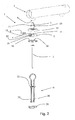
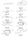
- the toilet hinge fastening arrangement 1 is depicted in Fig. 2 , 3 and 4a to 4m in further details together with the toilet hinge arrangement 7.
- the shown embodiment comprise; a base member 2, a fastener 3, a shaft member 5, a locking member 8, a cover 14, an underlay member 16 and an anchor assembly 19.
- the lower face of the base member 2 is adapted to abut the toilet bowl.
- a resilient underlay member 16 is located between the base member 2 and the toilet bowl, to avoid stress concentrations in the base member 2.
- Both the base member 2 and underlay member 16 has a mounting hole 4, 26 for the fastener 3. Both mounting holes 4, 26 may be slotted to provide means for adjusting the position of the base member 2.
- the mounting hole 4 in the base member 2 is preferably adapted to accommodate the head of the fastener 3, such that is flush with the bottom surface of the grove 9 in the base member 2.
- the head of the fastener 3 may be counter sunk, flat or any other suitable shape.
- the fastener 3 connects to a threaded anchor member 21 of the anchor assembly 19, such that it secures the base member 2 to the toilet bowl when the fastener 3 is tightened.
- the anchor assembly 19 comprise two elongated leg members 20 and a collar member 22.
- the collar member 22 has an opening for the fastener 3.
- the anchor assembly 19 is inserted through a hole in the toilet bowl defined by a wall with a concealed opening on one side with a support surface for the anchor member 21 and a support surface for the collar member 22 on the opposite side.
- the wall being sandwiched between the anchor member 21 and the collar member 22.
- the leg members 20 are used to angle the anchor member 21 after it has passed the hole in the toilet bowl, such that it is supported against the concealed surface.
- the shaft member 5 is slid sideways into the grove 9, guided by a first protrusion 11 on one end of the shaft member 5 and a complementary first recess 10 in the base member 2.
- the opposite end of the shaft member 5 interfaces with fastening means 6 in the toilet hinge arrangement 7.
- the locking member 8 is slid sideways into the grove 9, guided by a second protrusion 13 on the locking member 8 and a second recess 12 on the base member 2.
- the cover 14 is housing the base member 2, the underlay member 16, the locking member 8 and part of the shaft member 5.
- the part of the shaft member 5, that extends above the cover 14 through an opening in the cover 15 is housed within the toilet hinge arrangement 7.
- the cover 14 will retain the locking member 8 such that it remains in the locked position.
- the cover 14 will define what is visible from the outside of the toilet hinge fastening arrangement 1. This will provide an aesthetically pleasing and hygienic toilet hinge fastening arrangement 1.
- the toilet hinge fastening arrangement is installed as follows:
- the toilet hinge fastening arrangement 1 is now ready to support the toilet hinge arrangement 7 and toilet cover assembly 23.
- Fig. 5 is a detailed view of a second embodiment of the invention.
- the view shows part of the base member 2, which include the grove 9, and the locking member 8 respectively.
- the locking member 8 has two third protrusions 18 which will extend into two complementary recesses 17 in the base member 2 when the locking member is in the locked position.
- the protrusions 17 and recesses 18 will corporate in keeping the locking member 8 in the locked position.
- the first 10 and second 12 recesses are coinciding.
- Fig. 6 is a detailed view of a third embodiment of the invention.
- the view shows part of the base member 2, which include the grove 9, and the locking member 8 respectively.
- the base member 2 has a second recess 12 which is substantially parallel to a centreline through the shaft member 5 (not shown).
- the locking member has a second protrusion 13 which is complementary to the second recess 12.
- the locking member 8 is inserted into the grove 9 from above. The movement is substantially perpendicular to the direction in which the shaft member 5 (not shown) is inserted into the grove 9.
- the locking member 8 will be maintained in the locking position by gravity. This embodiment is able to withstand large sideways forces of the shaft member 5 (not shown).
Landscapes
- Health & Medical Sciences (AREA)
- Public Health (AREA)
- Toilet Supplies (AREA)
Description
- The invention relates to the field of fastening toilet seats to toilet bowls, and more particular to the fastening of hinges to toilet bowls.
-
WO 9111950 A1 claim 1. -
US 5,933,875 discloses a lift-off toilet seat hinge comprising a hinge base member adapted to be mounted on a toilet bowl, a hinge support member adapted to pivotally support a toilet seat, a locking member supported for rotation between a locked position, where the support member is secured to the base member, and an unlocked position. The base member and the locking member include corresponding arcuate projections which engage when the locking member is in the locking position. The locking member is used to clamp the hinge support member to the base member. Therefore the locking force needs to exceed the forces applied to the hinge support member. The projections of the locking member will be subject to a relatively high level of stress in the locked position in order to provide the necessary locking force. Furthermore it is required to manufacture the projections in the locking member and base member with small tolerances to achieve the necessary locking force. - It is therefore an object of the present invention to provide a toilet hinge which is easy to attach and remove from the toilet bowl, where the stresses within the locking member are low, and which is of a design with little complexity and few parts and which promote hygiene.
- According to the invention the object is obtained in that the shaft member is releasably retained in a grove provided in the base member, said grove having either a first recess or a first protrusion which is respectively adapted to cooperate with a complementary first protrusion or a first recess on the shaft member to secure the shaft member to the base member, that the locking member is adapted to be inserted into the grove, said grove having either a second recess or a second protrusion which is respectively adapted to cooperate with a complementary second protrusion or second recess on the locking member and providing a locked position for the locking member where the shaft member is retained.
- The shaft member is retained by the base member. It is hereby achieved that the majority of forces applied to the shaft member is taken up by the base member. The locking member is decoupled from the primary load path, and will only be subject to the forces required to keep the shaft member in place. Thus the stresses within the locking member are low.
- The shaft slides into the grove in a direction, which is substantially perpendicular to a centreline through the shaft member. The grove is having either a first recess or a first protrusion. If the grove has a first recess the shaft member will have a complementary protrusion that fits into said first recess to secure the shaft member to the base member. If the grove has a first protrusion the shaft member will have a complementary recess into which the first protrusion fits to secure the shaft member to the base member.
- The first recess and first protrusion may have various shapes, such as square, triangular, rounded, tapered, undercut or a combination. The shape is chosen to best solve their purpose of securing the shaft member to the base member and transferring the loads from the shaft member to the base member.
- The toilet hinge fastening arrangement is mounted to a toilet bowl and connected to a hinge arrangement, which is connected to a toilet seat. The toilet seat is connected to at least two hinges. Usually the toilet seat is symmetrical with a symmetry plane located between the two hinges. Therefore each hinge will carry half of the force that the toilet seat hinge arrangement is subject to. The forces are mainly in a direction forward and aft with respect to the toilet. The sideways forces are negligible.
- The locking member is moved to the locked position in the grove by a linear or nonlinear movement. The cooperating second protrusion and second recess in the locking member and base member respectively is guiding the movement of the locking member. If the grove is having a second recess the locking member will have a second protrusion and vice versa. Preferably the locking member will cover the part of the grove not already covered by the shaft member, such that the appearance of the combined base member, shaft member and locking member will be that of one single unit. Without voids or cavities which may be difficult to clean and thereby will promote bacteria growth.
- The second recess and second protrusion may have various shapes, such as square, triangular, rounded, tapered, undercut or a combination. The shape is chosen to best solve their purpose of guiding the locking member into the grove.
- Preferably the grove is located such that the shaft member is inserted in a sideways direction with respect to the toilet. It is an advantage if the locking member is made to a slight oversize to provide friction between the second protrusion and second recess. The friction will provide a locking force to keep the locking member in place. As the sideways forces are negligible the locking force need only to be small.
- According to a preferred embodiment, the first recess and the second recess are coinciding.
- In this embodiment there is only one recess. The shaft member and locking member will thereby share the recess. From a manufacturing point of view it is preferred to combine the undercut and first recess into one structural feature. This will remove some complexity from the design. It is especially suitable when the sideways forces are small. The locking force is dependent on friction between the recess and the second protrusion. Therefore the recess and second protrusion may be provided with a rough surface to increase the friction.
- According to a further preferred embodiment, the second recess is substantially parallel to a centreline through the shaft member.
- The shaft member will be retained by the first recess and the locking member by the second recess. The direction of the two recesses will be substantially perpendicular. Therefore sideways movement of the shaft member is prevented by mechanical means as long as the locking member is inserted. The achievable resistance against sideways forces of the shaft member is substantial and only limited by the strength of the second recess and second protrusion. Therefore this solution will be able to provide even large locking forces.
- According to a still further preferred embodiment, it comprise a cover for housing the base member and locking member, said cover having an opening for the shaft member.
- The cover surrounds the base member and the locking member. It is hereby achieved that the locking member is maintained in the locked position by the cover. The cover may abut the toilet bowl.
- Furthermore the cover will promote the hygiene and general appearance of the toilet hinge fastening arrangement.
- According to yet a further preferred embodiment, it comprises a resilient underlay member to be placed between the base member and a toilet bowl.
- When the fastener is tightened the resilient layer will even out any spaces between the base member and toilet bowl. Such spaces may be caused by manufacturing tolerances of the base member and toilet bowl. This will distribute the stresses across the surface of the base member such that stress concentrations are avoided.
- According to yet a still further preferred embodiment, the base member and the locking member includes a corresponding third recess and third protrusion, where the third protrusion extends into the third recess when the locking member is in the locked position.
- It is hereby achieved that the locking member itself is provided with mechanical means which will keep the locking member in the desired position inside the grove.
- The third recess and third protrusion may have various shapes, such as square, rounded, triangular or a combination. The shape is chosen to best solve the purpose of securing the locking member inside the grove to avoid accidentally release of the locking member, while it is possible for a person to release the locking member by applying the force of his or her fingers.
- The third recess and protrusion may add to the locking force and may therefore be used as part of the mechanical means to secure the shaft member.
- According to another preferred embodiment, the third recess is provided in the base member and the third protrusion is provided on the locking member.
- Depending on the design of especially the base member it may be practical to locate the third recess in the base member from a manufacturing point of view to be able to de-mould the base member. It may also be the case that the design of the locking member dictates the need to place the third protrusion on the locking member. This is subject to a trade-off analysis and a combined effort during design and preparations for manufacture.
- According to another further preferred embodiment, the third recess is provided in the locking member and the third protrusion is provided on the base member.
- Depending on the design of especially the base member it may be practical to locate the third protrusion on the base member from a manufacturing point of view to be able to de-mould the base member. It may also be the case that the design of the locking member dictates the need to place the third recess in the locking member. This is subject to a trade-off analysis and a combined effort during design and preparations for manufacture.
- According to another still further preferred embodiment, it comprise an anchor assembly for retaining the fastener, said anchor assembly being adapted to be inserted within an opening in the toilet bowl with a wall portion and a concealed side, said anchor assembly comprises two elongated leg members, a threaded anchor member coupled to said leg members at opposite end portions and a collar member secured to said leg members for sandwiching said wall portion between said collar and said anchor member.
- The anchor assembly will provide an attachment for the toilet hinge fastening arrangement to the toilet bowl which is easy to install especially if the attachment point for the anchor assembly is on a concealed side. This is often the case with toilet bowls for aesthetic and hygienic purposes.
- The anchor assembly may be chosen among known anchor assemblies.
- The different members of the toilet hinge fastening arrangement may be made of different materials such as plastics or metals.
- A major consideration when selecting materials is their ability to withstand the cleaning chemicals used for this particular application.
- In a preferred embodiment of the invention the anchor member is made of steel with a threaded collar member of POM or ABS. The fastener for the base member is made of stainless steel, the underlay member is made of a SEBS with a softener, the base member and locking member is made of a reinforced polymer such as PA, the shaft member is made of stainless steel, the cover is made of UREA.
- The invention will now be described in more detail with reference to a specific em-bodiment of the invention. The example may not be construed as limiting on the scope of the invention as the scope is determined by the appended claims, but the example merely serves to illustrate the invention.
- Fig. 1
- shows a toilet cover assembly including a toilet seat and a toilet hinge fastening arrangement,
- Fig. 2
- shows an expanded perspective view of the toilet hinge fastening arrangement,
- Fig. 3
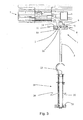
- shows a vertical sectional view through the toilet hinge fastening arrangement,
- Fig- 4a-m
- show different views of the elements constituting the toilet hinge fastening arrangement,
- Fig. 5
- show a detail view of a second embodiment of to the invention, and
- Fig. 6
- show a detail view of a third embodiment of the invention.
- In the detailed description identical or like elements will be given the same reference number within the entire set of figures. All details may therefore not be included with the description of each figure.
-
Fig. 1 illustrates atoilet cover assembly 23, comprising atoilet cover 24, atoilet seat 25, atoilet hinge arrangement 7 and two toilethinge fastening arrangements 1. Thetoilet cover assembly 23 is adapted to be installed on a toilet bowl (not shown) secured by the toilethinge fastening arrangement 1. - The toilet
hinge fastening arrangement 1 is depicted inFig. 2 ,3 and4a to 4m in further details together with thetoilet hinge arrangement 7. The shown embodiment comprise; abase member 2, afastener 3, ashaft member 5, a lockingmember 8, acover 14, anunderlay member 16 and ananchor assembly 19. - The lower face of the
base member 2 is adapted to abut the toilet bowl. Aresilient underlay member 16 is located between thebase member 2 and the toilet bowl, to avoid stress concentrations in thebase member 2. Both thebase member 2 andunderlay member 16 has a mountinghole fastener 3. Both mountingholes base member 2. The mountinghole 4 in thebase member 2 is preferably adapted to accommodate the head of thefastener 3, such that is flush with the bottom surface of thegrove 9 in thebase member 2. The head of thefastener 3 may be counter sunk, flat or any other suitable shape. - The
fastener 3 connects to a threadedanchor member 21 of theanchor assembly 19, such that it secures thebase member 2 to the toilet bowl when thefastener 3 is tightened. - Further to the
anchor member 21 theanchor assembly 19 comprise twoelongated leg members 20 and acollar member 22. Thecollar member 22 has an opening for thefastener 3. Theanchor assembly 19 is inserted through a hole in the toilet bowl defined by a wall with a concealed opening on one side with a support surface for theanchor member 21 and a support surface for thecollar member 22 on the opposite side. The wall being sandwiched between theanchor member 21 and thecollar member 22. Theleg members 20 are used to angle theanchor member 21 after it has passed the hole in the toilet bowl, such that it is supported against the concealed surface. - The
shaft member 5 is slid sideways into thegrove 9, guided by afirst protrusion 11 on one end of theshaft member 5 and a complementaryfirst recess 10 in thebase member 2. The opposite end of theshaft member 5 interfaces with fastening means 6 in thetoilet hinge arrangement 7. - The locking
member 8 is slid sideways into thegrove 9, guided by asecond protrusion 13 on the lockingmember 8 and asecond recess 12 on thebase member 2. - The
cover 14 is housing thebase member 2, theunderlay member 16, the lockingmember 8 and part of theshaft member 5. The part of theshaft member 5, that extends above thecover 14 through an opening in thecover 15 is housed within thetoilet hinge arrangement 7. Thecover 14 will retain the lockingmember 8 such that it remains in the locked position. Thecover 14 will define what is visible from the outside of the toilethinge fastening arrangement 1. This will provide an aesthetically pleasing and hygienic toilethinge fastening arrangement 1. - The toilet hinge fastening arrangement is installed as follows:
- the
anchor assembly 19 is installed in the toilet bowl, - the
under lay member 16 is positioned on the surface of the toilet bowl, - the
base member 2 is positioned on theunder lay member 16, - the
fastener 3 is inserted through thebase member 2, theunder lay member 16, thecollar member 22 and theanchor member 21, - the
fastener 3 is tightened to secure thebase member 2 to the toilet bowl, - the
shaft member 5 is inserted into thegrove 9, - the locking
member 8 is inserted into thegrove 9, - the
cover 14 is placed, - The toilet
hinge fastening arrangement 1 is now ready to support thetoilet hinge arrangement 7 andtoilet cover assembly 23. -
Fig. 5 is a detailed view of a second embodiment of the invention. The view shows part of thebase member 2, which include thegrove 9, and the lockingmember 8 respectively. The lockingmember 8 has twothird protrusions 18 which will extend into twocomplementary recesses 17 in thebase member 2 when the locking member is in the locked position. Theprotrusions 17 and recesses 18 will corporate in keeping the lockingmember 8 in the locked position. The first 10 and second 12 recesses are coinciding. -
Fig. 6 is a detailed view of a third embodiment of the invention. The view shows part of thebase member 2, which include thegrove 9, and the lockingmember 8 respectively. Thebase member 2 has asecond recess 12 which is substantially parallel to a centreline through the shaft member 5 (not shown). The locking member has asecond protrusion 13 which is complementary to thesecond recess 12. The lockingmember 8 is inserted into thegrove 9 from above. The movement is substantially perpendicular to the direction in which the shaft member 5 (not shown) is inserted into thegrove 9. The lockingmember 8 will be maintained in the locking position by gravity. This embodiment is able to withstand large sideways forces of the shaft member 5 (not shown).
Claims (9)
- Toilet hinge fastening arrangement (1) comprising;- a base member (2) having a lower face adapted to abut an upper face of a toilet bowl,- a fastener (3) for securing the base member (2) to the toilet bowl through a mounting hole (4) in said base member (2),- a shaft member (5) extending upwardly from the base member (2) and adapted to interface with fastening means (6) in a toilet hinge arrangement (7),- a locking member (8) adapted to secure the shaft member (5) to the base member (2), characterised in that the shaft member (5) is releasably retained in a grove (9) provided in the base member (2), said grove (9) having either a first recess (10) or a first protrusion (11) which is respectively adapted to cooperate with a complementary first protrusion (11) or a first recess (10) on the shaft member (5) to secure the shaft member (5) to the base member (2), that the locking member (8) is adapted to be inserted into the grove (9), said grove (9) having either a second recess (12) or a second protrusion (13) which is respectively adapted to cooperate with a complementary second protrusion (13) or second recess (12) on the locking member (8) and providing a locked position for the locking member (8) where the shaft member (5) is retained.
- Toilet hinge fastening arrangement according to claim 1, characterised in that the first recess (10) and the second recess (12) are coinciding.
- Toilet hinge fastening arrangement according to claim 1, characterised in that the second recess (12) is substantially parallel to a centreline through the shaft member (5).
- Toilet hinge fastening arrangement according to any of the preceding claims, characterised in that it comprise a cover (14) for housing the base member (2) and locking member (8), said cover (14) having an opening (15) for the shaft member (5).
- Toilet hinge fastening arrangement according to any of the preceding claims, characterised in that it comprise a resilient underlay member (16) to be placed between the base member (2) and a toilet bowl.
- Toilet lunge fastening arrangement according to any of the preceding claims, characterised in that the base member (2) and the locking member (8) includes a corresponding third recess (17) and third protrusion (18), where the third protrusion {18) extends into the third recess (17) when the locking member (8) is in the locked position.
- Toilet hinge fastening arrangement according to claim 6, characterised in that the third recess (17) is provided in the base member (2) and the third protrusion (18) is provided on the locking member (8).
- Toilet hinge fastening arrangement according to claim 7, characterised in that the third recess (17) is provided in the locking member (8) and the third protrusion (18) is provided on the base member (2).
- Toilet hinge fastening arrangement according to any of the preceding claims, characterised in that it comprise an anchor assembly (19) for retaining the fastener (3), said anchor assembly (19) being adapted to be inserted within an opening in the toilet bowl with a wall portion and a concealed side, said anchor assembly (19) comprises two elongated leg members (20), a threaded anchor member (21) coupled to said leg members (20) at opposite end portions and a collar member (22) secured to said leg members (20) for sandwiching said wall portion between said collar (22) and said anchor member (21).
Applications Claiming Priority (1)
| Application Number | Priority Date | Filing Date | Title |
|---|---|---|---|
| DKPA200801259A DK200801259A (en) | 2008-09-09 | 2008-09-09 | Toilet hinge fastening arrangement |
Publications (3)
| Publication Number | Publication Date |
|---|---|
| EP2160967A2 EP2160967A2 (en) | 2010-03-10 |
| EP2160967A3 EP2160967A3 (en) | 2013-12-25 |
| EP2160967B1 true EP2160967B1 (en) | 2015-03-18 |
Family
ID=41416019
Family Applications (1)
| Application Number | Title | Priority Date | Filing Date |
|---|---|---|---|
| EP09169824.1A Active EP2160967B1 (en) | 2008-09-09 | 2009-09-09 | Toilet hinge fastening arrangement |
Country Status (2)
| Country | Link |
|---|---|
| EP (1) | EP2160967B1 (en) |
| DK (2) | DK200801259A (en) |
Families Citing this family (1)
| Publication number | Priority date | Publication date | Assignee | Title |
|---|---|---|---|---|
| DE202018102956U1 (en) * | 2018-05-28 | 2019-09-03 | Franz Joseph Schütte GmbH | Hinge for a toilet seat set |
Family Cites Families (2)
| Publication number | Priority date | Publication date | Assignee | Title |
|---|---|---|---|---|
| JPH01108198U (en) * | 1988-01-12 | 1989-07-21 | ||
| DK40690A (en) * | 1990-02-15 | 1991-08-16 | Pressalit A S | Toilet seat / lid assembly |
-
2008
- 2008-09-09 DK DKPA200801259A patent/DK200801259A/en not_active Application Discontinuation
-
2009
- 2009-09-09 EP EP09169824.1A patent/EP2160967B1/en active Active
- 2009-09-09 DK DK09169824.1T patent/DK2160967T3/en active
Also Published As
| Publication number | Publication date |
|---|---|
| DK2160967T3 (en) | 2015-06-15 |
| EP2160967A3 (en) | 2013-12-25 |
| DK200801259A (en) | 2010-03-10 |
| EP2160967A2 (en) | 2010-03-10 |
Similar Documents
| Publication | Publication Date | Title |
|---|---|---|
| CA2794774C (en) | Armrest assembly for aircraft passenger seat | |
| NL2001200C2 (en) | Mounting for solar panels. | |
| EP2524095B1 (en) | Tiled structures and brackets therefor | |
| US8132766B2 (en) | Structrure having a mounting means | |
| CN101730777A (en) | door operating handle | |
| US20170335597A1 (en) | Door handle adapter with hidden fastener | |
| CN103987973A (en) | Piece of furniture and method for manufacturing furniture | |
| CN102469898A (en) | Bath fixture mounting system | |
| US6520463B1 (en) | Mounting bracket for wall mounted accessory | |
| US20140259362A1 (en) | Bathtub apron assembly | |
| US8327471B2 (en) | Seat assembly for a toilet | |
| EP2160967A2 (en) | Toilet hinge fastening arrangement | |
| EP2324745A2 (en) | Soft close hinge for a toilet seat | |
| US11479964B2 (en) | Rail profile with attachment mechanism and related methods | |
| US5551100A (en) | Bath bench | |
| US7611108B2 (en) | Sanitary element system with a system interface | |
| JP5532895B2 (en) | Aircraft restroom unit | |
| KR101027632B1 (en) | Toilet bowl with child seat cover | |
| US20190203877A1 (en) | System and method for wall mounting with a rotating bushing | |
| US20110283455A1 (en) | Baby change table | |
| US20140215700A1 (en) | Easy-Install Toilet Seat | |
| US20070125923A1 (en) | Small household fixtures with wall mounting fixture assembly | |
| CZ298306B6 (en) | Chair | |
| CN201559596U (en) | Connecting structure of automobile interior-decoration guard plate | |
| WO2013082664A1 (en) | A support element or bracket |
Legal Events
| Date | Code | Title | Description |
|---|---|---|---|
| PUAI | Public reference made under article 153(3) epc to a published international application that has entered the european phase |
Free format text: ORIGINAL CODE: 0009012 |
|
| AK | Designated contracting states |
Kind code of ref document: A2 Designated state(s): AT BE BG CH CY CZ DE DK EE ES FI FR GB GR HR HU IE IS IT LI LT LU LV MC MK MT NL NO PL PT RO SE SI SK SM TR |
|
| PUAL | Search report despatched |
Free format text: ORIGINAL CODE: 0009013 |
|
| AK | Designated contracting states |
Kind code of ref document: A3 Designated state(s): AT BE BG CH CY CZ DE DK EE ES FI FR GB GR HR HU IE IS IT LI LT LU LV MC MK MT NL NO PL PT RO SE SI SK SM TR |
|
| RIC1 | Information provided on ipc code assigned before grant |
Ipc: A47K 13/12 20060101AFI20131119BHEP Ipc: A47K 13/26 20060101ALI20131119BHEP |
|
| 17P | Request for examination filed |
Effective date: 20140625 |
|
| RBV | Designated contracting states (corrected) |
Designated state(s): AT BE BG CH CY CZ DE DK EE ES FI FR GB GR HR HU IE IS IT LI LT LU LV MC MK MT NL NO PL PT RO SE SI SK SM TR |
|
| GRAP | Despatch of communication of intention to grant a patent |
Free format text: ORIGINAL CODE: EPIDOSNIGR1 |
|
| INTG | Intention to grant announced |
Effective date: 20141008 |
|
| GRAS | Grant fee paid |
Free format text: ORIGINAL CODE: EPIDOSNIGR3 |
|
| GRAA | (expected) grant |
Free format text: ORIGINAL CODE: 0009210 |
|
| AK | Designated contracting states |
Kind code of ref document: B1 Designated state(s): AT BE BG CH CY CZ DE DK EE ES FI FR GB GR HR HU IE IS IT LI LT LU LV MC MK MT NL NO PL PT RO SE SI SK SM TR |
|
| REG | Reference to a national code |
Ref country code: GB Ref legal event code: FG4D |
|
| REG | Reference to a national code |
Ref country code: CH Ref legal event code: EP |
|
| REG | Reference to a national code |
Ref country code: IE Ref legal event code: FG4D |
|
| REG | Reference to a national code |
Ref country code: AT Ref legal event code: REF Ref document number: 715980 Country of ref document: AT Kind code of ref document: T Effective date: 20150415 |
|
| REG | Reference to a national code |
Ref country code: DE Ref legal event code: R096 Ref document number: 602009030012 Country of ref document: DE Effective date: 20150430 |
|
| REG | Reference to a national code |
Ref country code: DK Ref legal event code: T3 Effective date: 20150611 |
|
| REG | Reference to a national code |
Ref country code: NL Ref legal event code: VDEP Effective date: 20150318 |
|
| REG | Reference to a national code |
Ref country code: NL Ref legal event code: VDEP Effective date: 20150318 |
|
| PG25 | Lapsed in a contracting state [announced via postgrant information from national office to epo] |
Ref country code: SE Free format text: LAPSE BECAUSE OF FAILURE TO SUBMIT A TRANSLATION OF THE DESCRIPTION OR TO PAY THE FEE WITHIN THE PRESCRIBED TIME-LIMIT Effective date: 20150318 Ref country code: HR Free format text: LAPSE BECAUSE OF FAILURE TO SUBMIT A TRANSLATION OF THE DESCRIPTION OR TO PAY THE FEE WITHIN THE PRESCRIBED TIME-LIMIT Effective date: 20150318 Ref country code: NO Free format text: LAPSE BECAUSE OF FAILURE TO SUBMIT A TRANSLATION OF THE DESCRIPTION OR TO PAY THE FEE WITHIN THE PRESCRIBED TIME-LIMIT Effective date: 20150618 Ref country code: FI Free format text: LAPSE BECAUSE OF FAILURE TO SUBMIT A TRANSLATION OF THE DESCRIPTION OR TO PAY THE FEE WITHIN THE PRESCRIBED TIME-LIMIT Effective date: 20150318 Ref country code: LT Free format text: LAPSE BECAUSE OF FAILURE TO SUBMIT A TRANSLATION OF THE DESCRIPTION OR TO PAY THE FEE WITHIN THE PRESCRIBED TIME-LIMIT Effective date: 20150318 |
|
| REG | Reference to a national code |
Ref country code: AT Ref legal event code: MK05 Ref document number: 715980 Country of ref document: AT Kind code of ref document: T Effective date: 20150318 |
|
| REG | Reference to a national code |
Ref country code: LT Ref legal event code: MG4D |
|
| PG25 | Lapsed in a contracting state [announced via postgrant information from national office to epo] |
Ref country code: GR Free format text: LAPSE BECAUSE OF FAILURE TO SUBMIT A TRANSLATION OF THE DESCRIPTION OR TO PAY THE FEE WITHIN THE PRESCRIBED TIME-LIMIT Effective date: 20150619 Ref country code: LV Free format text: LAPSE BECAUSE OF FAILURE TO SUBMIT A TRANSLATION OF THE DESCRIPTION OR TO PAY THE FEE WITHIN THE PRESCRIBED TIME-LIMIT Effective date: 20150318 |
|
| PG25 | Lapsed in a contracting state [announced via postgrant information from national office to epo] |
Ref country code: NL Free format text: LAPSE BECAUSE OF FAILURE TO SUBMIT A TRANSLATION OF THE DESCRIPTION OR TO PAY THE FEE WITHIN THE PRESCRIBED TIME-LIMIT Effective date: 20150318 |
|
| PG25 | Lapsed in a contracting state [announced via postgrant information from national office to epo] |
Ref country code: RO Free format text: LAPSE BECAUSE OF FAILURE TO SUBMIT A TRANSLATION OF THE DESCRIPTION OR TO PAY THE FEE WITHIN THE PRESCRIBED TIME-LIMIT Effective date: 20150318 Ref country code: CZ Free format text: LAPSE BECAUSE OF FAILURE TO SUBMIT A TRANSLATION OF THE DESCRIPTION OR TO PAY THE FEE WITHIN THE PRESCRIBED TIME-LIMIT Effective date: 20150318 Ref country code: SK Free format text: LAPSE BECAUSE OF FAILURE TO SUBMIT A TRANSLATION OF THE DESCRIPTION OR TO PAY THE FEE WITHIN THE PRESCRIBED TIME-LIMIT Effective date: 20150318 Ref country code: ES Free format text: LAPSE BECAUSE OF FAILURE TO SUBMIT A TRANSLATION OF THE DESCRIPTION OR TO PAY THE FEE WITHIN THE PRESCRIBED TIME-LIMIT Effective date: 20150318 Ref country code: EE Free format text: LAPSE BECAUSE OF FAILURE TO SUBMIT A TRANSLATION OF THE DESCRIPTION OR TO PAY THE FEE WITHIN THE PRESCRIBED TIME-LIMIT Effective date: 20150318 Ref country code: PT Free format text: LAPSE BECAUSE OF FAILURE TO SUBMIT A TRANSLATION OF THE DESCRIPTION OR TO PAY THE FEE WITHIN THE PRESCRIBED TIME-LIMIT Effective date: 20150720 |
|
| PG25 | Lapsed in a contracting state [announced via postgrant information from national office to epo] |
Ref country code: IS Free format text: LAPSE BECAUSE OF FAILURE TO SUBMIT A TRANSLATION OF THE DESCRIPTION OR TO PAY THE FEE WITHIN THE PRESCRIBED TIME-LIMIT Effective date: 20150718 Ref country code: AT Free format text: LAPSE BECAUSE OF FAILURE TO SUBMIT A TRANSLATION OF THE DESCRIPTION OR TO PAY THE FEE WITHIN THE PRESCRIBED TIME-LIMIT Effective date: 20150318 Ref country code: PL Free format text: LAPSE BECAUSE OF FAILURE TO SUBMIT A TRANSLATION OF THE DESCRIPTION OR TO PAY THE FEE WITHIN THE PRESCRIBED TIME-LIMIT Effective date: 20150318 |
|
| REG | Reference to a national code |
Ref country code: DE Ref legal event code: R097 Ref document number: 602009030012 Country of ref document: DE |
|
| PG25 | Lapsed in a contracting state [announced via postgrant information from national office to epo] |
Ref country code: IT Free format text: LAPSE BECAUSE OF FAILURE TO SUBMIT A TRANSLATION OF THE DESCRIPTION OR TO PAY THE FEE WITHIN THE PRESCRIBED TIME-LIMIT Effective date: 20150318 |
|
| PLBE | No opposition filed within time limit |
Free format text: ORIGINAL CODE: 0009261 |
|
| STAA | Information on the status of an ep patent application or granted ep patent |
Free format text: STATUS: NO OPPOSITION FILED WITHIN TIME LIMIT |
|
| 26N | No opposition filed |
Effective date: 20151221 |
|
| PG25 | Lapsed in a contracting state [announced via postgrant information from national office to epo] |
Ref country code: SI Free format text: LAPSE BECAUSE OF FAILURE TO SUBMIT A TRANSLATION OF THE DESCRIPTION OR TO PAY THE FEE WITHIN THE PRESCRIBED TIME-LIMIT Effective date: 20150318 |
|
| PG25 | Lapsed in a contracting state [announced via postgrant information from national office to epo] |
Ref country code: MC Free format text: LAPSE BECAUSE OF FAILURE TO SUBMIT A TRANSLATION OF THE DESCRIPTION OR TO PAY THE FEE WITHIN THE PRESCRIBED TIME-LIMIT Effective date: 20150318 Ref country code: LU Free format text: LAPSE BECAUSE OF FAILURE TO SUBMIT A TRANSLATION OF THE DESCRIPTION OR TO PAY THE FEE WITHIN THE PRESCRIBED TIME-LIMIT Effective date: 20150909 |
|
| REG | Reference to a national code |
Ref country code: CH Ref legal event code: PL |
|
| GBPC | Gb: european patent ceased through non-payment of renewal fee |
Effective date: 20150909 |
|
| REG | Reference to a national code |
Ref country code: IE Ref legal event code: MM4A |
|
| REG | Reference to a national code |
Ref country code: FR Ref legal event code: ST Effective date: 20160531 |
|
| PG25 | Lapsed in a contracting state [announced via postgrant information from national office to epo] |
Ref country code: IE Free format text: LAPSE BECAUSE OF NON-PAYMENT OF DUE FEES Effective date: 20150909 Ref country code: LI Free format text: LAPSE BECAUSE OF NON-PAYMENT OF DUE FEES Effective date: 20150930 Ref country code: CH Free format text: LAPSE BECAUSE OF NON-PAYMENT OF DUE FEES Effective date: 20150930 Ref country code: GB Free format text: LAPSE BECAUSE OF NON-PAYMENT OF DUE FEES Effective date: 20150909 |
|
| PG25 | Lapsed in a contracting state [announced via postgrant information from national office to epo] |
Ref country code: BE Free format text: LAPSE BECAUSE OF FAILURE TO SUBMIT A TRANSLATION OF THE DESCRIPTION OR TO PAY THE FEE WITHIN THE PRESCRIBED TIME-LIMIT Effective date: 20150318 Ref country code: FR Free format text: LAPSE BECAUSE OF NON-PAYMENT OF DUE FEES Effective date: 20150930 |
|
| PG25 | Lapsed in a contracting state [announced via postgrant information from national office to epo] |
Ref country code: MT Free format text: LAPSE BECAUSE OF FAILURE TO SUBMIT A TRANSLATION OF THE DESCRIPTION OR TO PAY THE FEE WITHIN THE PRESCRIBED TIME-LIMIT Effective date: 20150318 |
|
| PG25 | Lapsed in a contracting state [announced via postgrant information from national office to epo] |
Ref country code: HU Free format text: LAPSE BECAUSE OF FAILURE TO SUBMIT A TRANSLATION OF THE DESCRIPTION OR TO PAY THE FEE WITHIN THE PRESCRIBED TIME-LIMIT; INVALID AB INITIO Effective date: 20090909 Ref country code: BG Free format text: LAPSE BECAUSE OF FAILURE TO SUBMIT A TRANSLATION OF THE DESCRIPTION OR TO PAY THE FEE WITHIN THE PRESCRIBED TIME-LIMIT Effective date: 20150318 Ref country code: SM Free format text: LAPSE BECAUSE OF FAILURE TO SUBMIT A TRANSLATION OF THE DESCRIPTION OR TO PAY THE FEE WITHIN THE PRESCRIBED TIME-LIMIT Effective date: 20150318 |
|
| PG25 | Lapsed in a contracting state [announced via postgrant information from national office to epo] |
Ref country code: CY Free format text: LAPSE BECAUSE OF FAILURE TO SUBMIT A TRANSLATION OF THE DESCRIPTION OR TO PAY THE FEE WITHIN THE PRESCRIBED TIME-LIMIT Effective date: 20150318 |
|
| PG25 | Lapsed in a contracting state [announced via postgrant information from national office to epo] |
Ref country code: TR Free format text: LAPSE BECAUSE OF FAILURE TO SUBMIT A TRANSLATION OF THE DESCRIPTION OR TO PAY THE FEE WITHIN THE PRESCRIBED TIME-LIMIT Effective date: 20150318 |
|
| PG25 | Lapsed in a contracting state [announced via postgrant information from national office to epo] |
Ref country code: MK Free format text: LAPSE BECAUSE OF FAILURE TO SUBMIT A TRANSLATION OF THE DESCRIPTION OR TO PAY THE FEE WITHIN THE PRESCRIBED TIME-LIMIT Effective date: 20150318 |
|
| P01 | Opt-out of the competence of the unified patent court (upc) registered |
Effective date: 20230511 |
|
| PGFP | Annual fee paid to national office [announced via postgrant information from national office to epo] |
Ref country code: DK Payment date: 20250925 Year of fee payment: 17 Ref country code: DE Payment date: 20250929 Year of fee payment: 17 |