EP2160646B1 - Mach zehnder modulator - Google Patents
Mach zehnder modulator Download PDFInfo
- Publication number
- EP2160646B1 EP2160646B1 EP08779374A EP08779374A EP2160646B1 EP 2160646 B1 EP2160646 B1 EP 2160646B1 EP 08779374 A EP08779374 A EP 08779374A EP 08779374 A EP08779374 A EP 08779374A EP 2160646 B1 EP2160646 B1 EP 2160646B1
- Authority
- EP
- European Patent Office
- Prior art keywords
- arms
- light
- modulator
- combiner
- arm
- Prior art date
- Legal status (The legal status is an assumption and is not a legal conclusion. Google has not performed a legal analysis and makes no representation as to the accuracy of the status listed.)
- Not-in-force
Links
Images
Classifications
-
- G—PHYSICS
- G02—OPTICS
- G02F—OPTICAL DEVICES OR ARRANGEMENTS FOR THE CONTROL OF LIGHT BY MODIFICATION OF THE OPTICAL PROPERTIES OF THE MEDIA OF THE ELEMENTS INVOLVED THEREIN; NON-LINEAR OPTICS; FREQUENCY-CHANGING OF LIGHT; OPTICAL LOGIC ELEMENTS; OPTICAL ANALOGUE/DIGITAL CONVERTERS
- G02F1/00—Devices or arrangements for the control of the intensity, colour, phase, polarisation or direction of light arriving from an independent light source, e.g. switching, gating or modulating; Non-linear optics
- G02F1/01—Devices or arrangements for the control of the intensity, colour, phase, polarisation or direction of light arriving from an independent light source, e.g. switching, gating or modulating; Non-linear optics for the control of the intensity, phase, polarisation or colour
- G02F1/21—Devices or arrangements for the control of the intensity, colour, phase, polarisation or direction of light arriving from an independent light source, e.g. switching, gating or modulating; Non-linear optics for the control of the intensity, phase, polarisation or colour by interference
- G02F1/225—Devices or arrangements for the control of the intensity, colour, phase, polarisation or direction of light arriving from an independent light source, e.g. switching, gating or modulating; Non-linear optics for the control of the intensity, phase, polarisation or colour by interference in an optical waveguide structure
-
- G—PHYSICS
- G02—OPTICS
- G02F—OPTICAL DEVICES OR ARRANGEMENTS FOR THE CONTROL OF LIGHT BY MODIFICATION OF THE OPTICAL PROPERTIES OF THE MEDIA OF THE ELEMENTS INVOLVED THEREIN; NON-LINEAR OPTICS; FREQUENCY-CHANGING OF LIGHT; OPTICAL LOGIC ELEMENTS; OPTICAL ANALOGUE/DIGITAL CONVERTERS
- G02F1/00—Devices or arrangements for the control of the intensity, colour, phase, polarisation or direction of light arriving from an independent light source, e.g. switching, gating or modulating; Non-linear optics
- G02F1/01—Devices or arrangements for the control of the intensity, colour, phase, polarisation or direction of light arriving from an independent light source, e.g. switching, gating or modulating; Non-linear optics for the control of the intensity, phase, polarisation or colour
- G02F1/21—Devices or arrangements for the control of the intensity, colour, phase, polarisation or direction of light arriving from an independent light source, e.g. switching, gating or modulating; Non-linear optics for the control of the intensity, phase, polarisation or colour by interference
- G02F1/212—Mach-Zehnder type
-
- G—PHYSICS
- G02—OPTICS
- G02F—OPTICAL DEVICES OR ARRANGEMENTS FOR THE CONTROL OF LIGHT BY MODIFICATION OF THE OPTICAL PROPERTIES OF THE MEDIA OF THE ELEMENTS INVOLVED THEREIN; NON-LINEAR OPTICS; FREQUENCY-CHANGING OF LIGHT; OPTICAL LOGIC ELEMENTS; OPTICAL ANALOGUE/DIGITAL CONVERTERS
- G02F2201/00—Constructional arrangements not provided for in groups G02F1/00 - G02F7/00
- G02F2201/14—Constructional arrangements not provided for in groups G02F1/00 - G02F7/00 asymmetric
-
- G—PHYSICS
- G02—OPTICS
- G02F—OPTICAL DEVICES OR ARRANGEMENTS FOR THE CONTROL OF LIGHT BY MODIFICATION OF THE OPTICAL PROPERTIES OF THE MEDIA OF THE ELEMENTS INVOLVED THEREIN; NON-LINEAR OPTICS; FREQUENCY-CHANGING OF LIGHT; OPTICAL LOGIC ELEMENTS; OPTICAL ANALOGUE/DIGITAL CONVERTERS
- G02F2203/00—Function characteristic
- G02F2203/21—Thermal instability, i.e. DC drift, of an optical modulator; Arrangements or methods for the reduction thereof
Definitions
- An MZ modulator consists of a splitter that splits incident light in one wave guide into two modulator arms and a combiner that combines the light from the two arms into an output mode.
- a Mach Zehnder (MZ) modulator is used to modulate incident light so that the light is amplified or so that an extinction, due to interference between the light in the two arms, takes place.
- Frequency chirp is a change in the wavelength, when a laser is modulated with a MZ at high bit rates.
- One known solution is to have an unequal splitting ratio, so that more power is launched into one arm then the other arm. Additionally an unequal combiner ratio is beneficial for the maximum throughput.
- US 6,532,315 shows a Mach-Zehnder modulator where there is a variable attenuator in one waveguide arm between an optical splitter and a modulator.
- JUERG LEUTHOLD ET AL "All-Optical Space Switches with Gain and Principally Ideal Extinction Ratios", IEEE JOURNAL OF QUANTUM ELECTRONICS, IEEE SERVICE CENTER, PISCATAWAY, NJ, USA, vol. 34, no. 4, 1 April 1998 (1998-04-01), XP011051902, ISSN: 0018-9197 is a paper showing optically controlled interferometers with asymmetric splitters and combiners. The purpose is to compensate for asymmetries in amplification in order to achieve good extinction ratios. There are no intentional losses in the interferometer.
- US 2004/067020 shows a method to control a Mach-Zehnder modulator so that it transmits signals in a duobinary format in the case where the Mach-Zehnder modulator material exhibits non-linearities in the refractive index vs voltage characteristic. There are no intentional attenuators in the interferometer.
- WO 2006/106807 shows a Mach-Zehnder modulator where the purpose is to have different propagation constants in the two wave guide arms, so that coupling is reduced between the two waveguides.
- the present invention solves this problem.
- the present invention refers to a Mach Zehnder (MZ) modulator comprising a splitter for splitting incident light in one wave guide into two modulator arms of the MZ and comprising a combiner that combines light from the two arms into an output mode, where electrodes are present in connection with said arms for changing the refractive index in said arms in order to modulate incident light so that the light is amplified or so that an extinction, due to interference between the light in the two arms, takes place, and is characterised in, that the splitter is arranged to split incident light equally into the two arms and in that a part of one of the arms between said electrode and said combiner is designed to cause an intentional loss of light in the wave guide so that a desired asymmetry in transmission of the two arms occurs.
- MZ Mach Zehnder
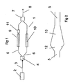
- FIG. 1 schematically shows a Mach Zehnder (MZ) modulator 1.
- MZ Mach Zehnder
- Light from a laser 2 is fed to the MZ via a wave guide in form of an optical fibre 3.
- the MZ comprises a splitter 4 for splitting incident light in said wave guide 3 into two modulator arms 5, 6 of the MZ.
- the MZ also comprises a combiner 7 that combines light from the two arms into an output mode.
- the light is guided from the MZ in a wave guide in form of an optical fibre 8.
- Electrodes 9, 10 are present in connection with said arms 5, 6 for changing the refractive index in said arms in order to modulate incident light so that the light is amplified or so that an extinction, due to interference between the light in the two arms, takes place.
- the electrodes are activated according to a push - pull sequence, where one of the electrodes are provided with a positive voltage while the other electrode is provided with a negative voltage and vice versa.
- the invention is characterised in, that the splitter 4 is arranged to split incident light equally into the two arms 5, 6 and in that in a part 11 of one 5 of the arms between said electrode 9 and said combiner 7 is designed to cause an intentional loss of light in the arm 5 so that a desired asymmetry in transmission of the two arms 5, 6 occurs.
- the splitter may be a multimode modulator interferometer (MMI).
- MMI multimode modulator interferometer
- the man skilled in the art has no problem of designing the said part such that the light in one arm is in phase, or approximately in phase, with the light in the other arm, or that the light in one arm is 180 degrees out of phase, or approximately out of phase, with the light in the other arm respectively, when combined in the combiner 7 and that the amplitude of the light in the two arms are equal.
- the output light in the wave guide 8 is amplified or will be extinguished.
- said part comprises a loss device attenuator.
- said part comprises a widening of the arm along a short length, at 12 in Figure 2 , of the arm followed by a decrease of width of the arm, at 13 in Figure 2 , along a length long enough to avoid reflections but short enough for the light propagation to be nonadiabatic.
- the attenuator 11 can cause that 40 % of the light at the combiner comes from the arm 5 with the attenuator, while 60 % of the light comes from the other arm 6.
- the combiner that has an inherent uneven splitting ratio.
Landscapes
- Physics & Mathematics (AREA)
- Nonlinear Science (AREA)
- General Physics & Mathematics (AREA)
- Optics & Photonics (AREA)
- Optical Modulation, Optical Deflection, Nonlinear Optics, Optical Demodulation, Optical Logic Elements (AREA)
- Optical Integrated Circuits (AREA)
Abstract
Description
- An MZ modulator consists of a splitter that splits incident light in one wave guide into two modulator arms and a combiner that combines the light from the two arms into an output mode.
- A Mach Zehnder (MZ) modulator is used to modulate incident light so that the light is amplified or so that an extinction, due to interference between the light in the two arms, takes place.
- In an MZ modulator it is beneficial to have an unequal amount of light passing through the two arms to the output mode. This is to ensure a large ratio between the power levels between the on and off state, i.e. amplification or extinction, and at the same time obtain a desired frequency chirp properties. Frequency chirp is a change in the wavelength, when a laser is modulated with a MZ at high bit rates.
- One known solution is to have an unequal splitting ratio, so that more power is launched into one arm then the other arm. Additionally an unequal combiner ratio is beneficial for the maximum throughput.
-
US 6,532,315 shows a Mach-Zehnder modulator where there is a variable attenuator in one waveguide arm between an optical splitter and a modulator. - JUERG LEUTHOLD ET AL: "All-Optical Space Switches with Gain and Principally Ideal Extinction Ratios", IEEE JOURNAL OF QUANTUM ELECTRONICS, IEEE SERVICE CENTER, PISCATAWAY, NJ, USA, vol. 34, no. 4, 1 April 1998 (1998-04-01), XP011051902, ISSN: 0018-9197 is a paper showing optically controlled interferometers with asymmetric splitters and combiners. The purpose is to compensate for asymmetries in amplification in order to achieve good extinction ratios. There are no intentional losses in the interferometer.
-
US 2004/067020 shows a method to control a Mach-Zehnder modulator so that it transmits signals in a duobinary format in the case where the Mach-Zehnder modulator material exhibits non-linearities in the refractive index vs voltage characteristic. There are no intentional attenuators in the interferometer. -
WO 2006/106807 shows a Mach-Zehnder modulator where the purpose is to have different propagation constants in the two wave guide arms, so that coupling is reduced between the two waveguides. - One disadvantage with an unequal splitting ratio is that different intensities of light are present in the two arms. The consequences of that is that when for example the input light power to the modulator is changed, the arm with higher light intensity will experience a stronger heating due to higher light absorption and higher photo current than the other arm. The change of the difference in heating causes a change of the phase difference between the arms. Since the MZ modulator is based on interferometry the changed phase difference may cause the modulator to mal function or require the bias voltages to be adjusted to compensate for the changed phase difference.
- The present invention solves this problem.
- The present invention refers to a Mach Zehnder (MZ) modulator comprising a splitter for splitting incident light in one wave guide into two modulator arms of the MZ and comprising a combiner that combines light from the two arms into an output mode, where electrodes are present in connection with said arms for changing the refractive index in said arms in order to modulate incident light so that the light is amplified or so that an extinction, due to interference between the light in the two arms, takes place, and is characterised in, that the splitter is arranged to split incident light equally into the two arms and in that a part of one of the arms between said electrode and said combiner is designed to cause an intentional loss of light in the wave guide so that a desired asymmetry in transmission of the two arms occurs.
- Below the present invention is described in more detail, partly in connection with exemplifying embodiments of the the invention and a drawing, where
-
Figure 1 schematically shows a MZ where the present invention is implemented -
Figure 2 schematically shows a for making an intentional loss of light in a waveguide. -
Figure 1 schematically shows a Mach Zehnder (MZ) modulator 1. Light from alaser 2 is fed to the MZ via a wave guide in form of anoptical fibre 3. The MZ comprises asplitter 4 for splitting incident light in saidwave guide 3 into twomodulator arms combiner 7 that combines light from the two arms into an output mode. The light is guided from the MZ in a wave guide in form of anoptical fibre 8.Electrodes arms - The invention is characterised in, that the
splitter 4 is arranged to split incident light equally into the twoarms part 11 of one 5 of the arms between saidelectrode 9 and saidcombiner 7 is designed to cause an intentional loss of light in thearm 5 so that a desired asymmetry in transmission of the twoarms - The splitter may be a multimode modulator interferometer (MMI).
- Hereby an equal splitting ratio is maintained and an asymmetry is created at the end of the MZ after the modulator electrodes. The asymmetry of light intensities will then cause a very small phase difference since a very short distance is subjected to the asymmetry and this short distance does not have modulator electrodes and is therefore never reverse biased. The absence of reverse bias leads to a low absorption of light. Then the change in difference in heating due to electric current in the electrodes, and in phase difference, between the two arms when changing the power level becomes small. Therefore, the device will work for a large range of input power.
- The man skilled in the art has no problem of designing the said part such that the light in one arm is in phase, or approximately in phase, with the light in the other arm, or that the light in one arm is 180 degrees out of phase, or approximately out of phase, with the light in the other arm respectively, when combined in the
combiner 7 and that the amplitude of the light in the two arms are equal. Hereby, the output light in thewave guide 8 is amplified or will be extinguished. - According to one preferred embodiment of the invention said part comprises a loss device attenuator.
- According to another preferred embodiment, illustrated in
Figure 2 , said part comprises a widening of the arm along a short length, at 12 inFigure 2 , of the arm followed by a decrease of width of the arm, at 13 inFigure 2 , along a length long enough to avoid reflections but short enough for the light propagation to be nonadiabatic. - As an example the
attenuator 11 can cause that 40 % of the light at the combiner comes from thearm 5 with the attenuator, while 60 % of the light comes from theother arm 6. - According to still another preferred embodiment, the combiner that has an inherent uneven splitting ratio.
- There are other ways to make an intentional loss such as using a branch and lead off some light or a directional coupler.
- The invention is not limited to the above described embodiments of the invention, but can be modified within the scope of the patent claims.
Claims (4)
- A Mach Zehnder (MZ) modulator (1) comprising a splitter (4) for splitting incident light in one wave guide (3) into two modulator arms (5,6) of the MZ and comprising a combiner (7) that combines light from the two arms (5,6) into an output mode, where electrodes (9,10) are present in connection with said arms (5,6) for changing the refractive index in said arms in order to modulate incident light so that the light is amplified or so that an extinction, due to interference between the light in the two arms, takes place, the splitter (4) is arranged to split incident light equally into the two arms (5,6) whereby a desired asymmetry in transmission of the two arms (5,6) occurs
characterised in that a part (11) of one of the arms (5) between said electrode (9) and said combiner (7) is designed to cause an intentional loss of light in the wave guide (5) - A Mach Zehnder modulator according to claim 1,
characterised in, that said part (11) comprises a loss device attenuator. - A Mach Zehnder modulator according to claim 1 or 2,
characterised in, that said part (11) comprises a widening of the arm (5) along a short length of the arm followed by a decrease of width of the arm (5) along a length long enough to avoid reflections but short enough for the light propagation to be nonadiabatic. - A Mach Zehnder modulator according to claim 1,
characterised in, that the combiner (7) has an inherent uneven splitting ratio.
Applications Claiming Priority (2)
| Application Number | Priority Date | Filing Date | Title |
|---|---|---|---|
| SE0701557A SE531373C2 (en) | 2007-06-27 | 2007-06-27 | Mach Zehnder modulator |
| PCT/SE2008/050692 WO2009002255A1 (en) | 2007-06-27 | 2008-06-10 | Mach zehnder modulator |
Publications (3)
| Publication Number | Publication Date |
|---|---|
| EP2160646A1 EP2160646A1 (en) | 2010-03-10 |
| EP2160646A4 EP2160646A4 (en) | 2010-12-29 |
| EP2160646B1 true EP2160646B1 (en) | 2011-12-21 |
Family
ID=40185879
Family Applications (1)
| Application Number | Title | Priority Date | Filing Date |
|---|---|---|---|
| EP08779374A Not-in-force EP2160646B1 (en) | 2007-06-27 | 2008-06-10 | Mach zehnder modulator |
Country Status (5)
| Country | Link |
|---|---|
| US (1) | US8306370B2 (en) |
| EP (1) | EP2160646B1 (en) |
| AT (1) | ATE538409T1 (en) |
| SE (1) | SE531373C2 (en) |
| WO (1) | WO2009002255A1 (en) |
Families Citing this family (4)
| Publication number | Priority date | Publication date | Assignee | Title |
|---|---|---|---|---|
| GB2486478A (en) * | 2010-12-16 | 2012-06-20 | Oclaro Technology Ltd | Mach-Zehnder Interferometers |
| HUE039713T2 (en) | 2012-06-08 | 2019-02-28 | Sensorion | H4 receptor inhibitors for treating tinnitus |
| JP7674856B2 (en) * | 2021-02-26 | 2025-05-12 | Tdk株式会社 | Optical modulation element and optical modulator |
| CN114185221B (en) * | 2021-11-03 | 2025-01-21 | 武汉光谷信息光电子创新中心有限公司 | A modulator and a modulation method |
Family Cites Families (9)
| Publication number | Priority date | Publication date | Assignee | Title |
|---|---|---|---|---|
| US5323406A (en) * | 1992-11-02 | 1994-06-21 | Yee Ting K | Photonic mixer for photonically multiplying two electrical signals in two optically interconnected interferometric modulators operated at modulation outside the linear range |
| US6226091B1 (en) * | 1998-09-24 | 2001-05-01 | Thomas & Betts International, Inc. | Optical fiber Mach-Zehnder interferometer fabricated with asymmetric couplers |
| US6532315B1 (en) | 2000-10-06 | 2003-03-11 | Donald J. Lenkszus | Variable chirp optical modulator having different length electrodes |
| GB2374945A (en) * | 2001-04-26 | 2002-10-30 | Jds Uniphase Corp | Mach-Zehnder Optical Modulator |
| US6760499B2 (en) * | 2001-07-31 | 2004-07-06 | Jds Uniphase Corporation | Birefringence compensated integrated optical switching or modulation device |
| US6522793B1 (en) * | 2001-11-21 | 2003-02-18 | Andrei Szilagyi | Low voltage electro-optic modulator with integrated driver |
| US6795594B2 (en) | 2002-10-03 | 2004-09-21 | Nortel Networks Limited | Duobinary modulation scheme for a Mach-Zehnder optical modulator |
| US7376310B2 (en) * | 2002-12-20 | 2008-05-20 | International Business Machines Corporation | Optical waveguide element with controlled birefringence |
| JP2007114222A (en) * | 2005-03-31 | 2007-05-10 | Sumitomo Osaka Cement Co Ltd | Light control element |
-
2007
- 2007-06-27 SE SE0701557A patent/SE531373C2/en not_active IP Right Cessation
-
2008
- 2008-06-10 US US12/666,400 patent/US8306370B2/en active Active
- 2008-06-10 WO PCT/SE2008/050692 patent/WO2009002255A1/en not_active Ceased
- 2008-06-10 EP EP08779374A patent/EP2160646B1/en not_active Not-in-force
- 2008-06-10 AT AT08779374T patent/ATE538409T1/en active
Also Published As
| Publication number | Publication date |
|---|---|
| ATE538409T1 (en) | 2012-01-15 |
| SE0701557L (en) | 2008-12-28 |
| US8306370B2 (en) | 2012-11-06 |
| WO2009002255A1 (en) | 2008-12-31 |
| EP2160646A4 (en) | 2010-12-29 |
| US20110007995A1 (en) | 2011-01-13 |
| SE531373C2 (en) | 2009-03-17 |
| EP2160646A1 (en) | 2010-03-10 |
Similar Documents
| Publication | Publication Date | Title |
|---|---|---|
| CA2561153C (en) | Optical modulator | |
| US8705900B2 (en) | Optical modulator | |
| US8374467B2 (en) | Optical device having a plurality of Mach-Zehnder modulators | |
| US7911675B2 (en) | Optical modulation device and optical semiconductor device | |
| CN101726801B (en) | Optical switching device and control method thereof | |
| US12199404B2 (en) | Semiconductor optical amplifier light combiner | |
| JP2013113917A (en) | Light modulating device and method for controlling the same | |
| US20090162014A1 (en) | Optical waveguide device and optical apparatus using optical waveguide device | |
| US8306370B2 (en) | Mach zehnder modulator | |
| Su et al. | Silicon photonic integrated wideband radio frequency self-interference cancellation chip for over-the-air in-band full-duplex communication | |
| Guo et al. | Integrated self-coherent optical transceivers for data center applications based on thin-film lithium niobate platform | |
| US6795594B2 (en) | Duobinary modulation scheme for a Mach-Zehnder optical modulator | |
| EP1760914B1 (en) | Wavelength conversion system, optical integrated device and wavelength conversion method | |
| CN109856885A (en) | A Low Voltage Negative Chirp Modulator | |
| El-Fiky et al. | Dual parallel multielectrode traveling wave Mach–Zehnder modulator for 200 Gb/s intra-datacenter optical interconnects | |
| CN109946791B (en) | An electro-optical modulator, single-polarization IQ modulator, and dual-polarization IQ modulator | |
| JP2013122546A (en) | Semiconductor optical phase modulator and method for driving the same | |
| CN118915335A (en) | High-linearity integrated cascade modulator | |
| Vyrsokinos et al. | DPSK-Demodulation based on Ultra-Compact micron-scale SOI platform | |
| CN113141213B (en) | Coherent transmitter, method for controlling coherent transmitter and coherent transceiving system | |
| Talkhooncheh et al. | A 200gb/s qam-16 silicon photonic transmitter with 4 binary-driven eams in an mzi structure | |
| Sugiyama et al. | Low-drive-voltage and compact RZ-DQPSK LiNbO3 Modulator | |
| Liu et al. | 200 Gbps photonic integrated chip on silicon platform | |
| Liao et al. | Silicon photonic modulator and integration for high-speed applications | |
| Kang et al. | Pulse-carver-free 50-Gb/s RZ-DQPSK generation using hybrid photonic-integrated electroabsorption modulators |
Legal Events
| Date | Code | Title | Description |
|---|---|---|---|
| PUAI | Public reference made under article 153(3) epc to a published international application that has entered the european phase |
Free format text: ORIGINAL CODE: 0009012 |
|
| 17P | Request for examination filed |
Effective date: 20091216 |
|
| AK | Designated contracting states |
Kind code of ref document: A1 Designated state(s): AT BE BG CH CY CZ DE DK EE ES FI FR GB GR HR HU IE IS IT LI LT LU LV MC MT NL NO PL PT RO SE SI SK TR |
|
| AX | Request for extension of the european patent |
Extension state: AL BA MK RS |
|
| DAX | Request for extension of the european patent (deleted) | ||
| A4 | Supplementary search report drawn up and despatched |
Effective date: 20101129 |
|
| RIC1 | Information provided on ipc code assigned before grant |
Ipc: G02F 1/225 20060101AFI20110728BHEP |
|
| GRAP | Despatch of communication of intention to grant a patent |
Free format text: ORIGINAL CODE: EPIDOSNIGR1 |
|
| GRAS | Grant fee paid |
Free format text: ORIGINAL CODE: EPIDOSNIGR3 |
|
| GRAA | (expected) grant |
Free format text: ORIGINAL CODE: 0009210 |
|
| AK | Designated contracting states |
Kind code of ref document: B1 Designated state(s): AT BE BG CH CY CZ DE DK EE ES FI FR GB GR HR HU IE IS IT LI LT LU LV MC MT NL NO PL PT RO SE SI SK TR |
|
| REG | Reference to a national code |
Ref country code: GB Ref legal event code: FG4D |
|
| REG | Reference to a national code |
Ref country code: CH Ref legal event code: EP |
|
| REG | Reference to a national code |
Ref country code: AT Ref legal event code: REF Ref document number: 538409 Country of ref document: AT Kind code of ref document: T Effective date: 20120115 |
|
| REG | Reference to a national code |
Ref country code: IE Ref legal event code: FG4D |
|
| REG | Reference to a national code |
Ref country code: DE Ref legal event code: R096 Ref document number: 602008012210 Country of ref document: DE Effective date: 20120301 |
|
| REG | Reference to a national code |
Ref country code: NL Ref legal event code: VDEP Effective date: 20111221 |
|
| PG25 | Lapsed in a contracting state [announced via postgrant information from national office to epo] |
Ref country code: NO Free format text: LAPSE BECAUSE OF FAILURE TO SUBMIT A TRANSLATION OF THE DESCRIPTION OR TO PAY THE FEE WITHIN THE PRESCRIBED TIME-LIMIT Effective date: 20120321 Ref country code: LT Free format text: LAPSE BECAUSE OF FAILURE TO SUBMIT A TRANSLATION OF THE DESCRIPTION OR TO PAY THE FEE WITHIN THE PRESCRIBED TIME-LIMIT Effective date: 20111221 |
|
| LTIE | Lt: invalidation of european patent or patent extension |
Effective date: 20111221 |
|
| PG25 | Lapsed in a contracting state [announced via postgrant information from national office to epo] |
Ref country code: SE Free format text: LAPSE BECAUSE OF FAILURE TO SUBMIT A TRANSLATION OF THE DESCRIPTION OR TO PAY THE FEE WITHIN THE PRESCRIBED TIME-LIMIT Effective date: 20111221 Ref country code: LV Free format text: LAPSE BECAUSE OF FAILURE TO SUBMIT A TRANSLATION OF THE DESCRIPTION OR TO PAY THE FEE WITHIN THE PRESCRIBED TIME-LIMIT Effective date: 20111221 Ref country code: SI Free format text: LAPSE BECAUSE OF FAILURE TO SUBMIT A TRANSLATION OF THE DESCRIPTION OR TO PAY THE FEE WITHIN THE PRESCRIBED TIME-LIMIT Effective date: 20111221 Ref country code: NL Free format text: LAPSE BECAUSE OF FAILURE TO SUBMIT A TRANSLATION OF THE DESCRIPTION OR TO PAY THE FEE WITHIN THE PRESCRIBED TIME-LIMIT Effective date: 20111221 Ref country code: GR Free format text: LAPSE BECAUSE OF FAILURE TO SUBMIT A TRANSLATION OF THE DESCRIPTION OR TO PAY THE FEE WITHIN THE PRESCRIBED TIME-LIMIT Effective date: 20120322 Ref country code: HR Free format text: LAPSE BECAUSE OF FAILURE TO SUBMIT A TRANSLATION OF THE DESCRIPTION OR TO PAY THE FEE WITHIN THE PRESCRIBED TIME-LIMIT Effective date: 20111221 |
|
| PG25 | Lapsed in a contracting state [announced via postgrant information from national office to epo] |
Ref country code: BE Free format text: LAPSE BECAUSE OF FAILURE TO SUBMIT A TRANSLATION OF THE DESCRIPTION OR TO PAY THE FEE WITHIN THE PRESCRIBED TIME-LIMIT Effective date: 20111221 Ref country code: CY Free format text: LAPSE BECAUSE OF FAILURE TO SUBMIT A TRANSLATION OF THE DESCRIPTION OR TO PAY THE FEE WITHIN THE PRESCRIBED TIME-LIMIT Effective date: 20111221 |
|
| PG25 | Lapsed in a contracting state [announced via postgrant information from national office to epo] |
Ref country code: EE Free format text: LAPSE BECAUSE OF FAILURE TO SUBMIT A TRANSLATION OF THE DESCRIPTION OR TO PAY THE FEE WITHIN THE PRESCRIBED TIME-LIMIT Effective date: 20111221 Ref country code: CZ Free format text: LAPSE BECAUSE OF FAILURE TO SUBMIT A TRANSLATION OF THE DESCRIPTION OR TO PAY THE FEE WITHIN THE PRESCRIBED TIME-LIMIT Effective date: 20111221 Ref country code: BG Free format text: LAPSE BECAUSE OF FAILURE TO SUBMIT A TRANSLATION OF THE DESCRIPTION OR TO PAY THE FEE WITHIN THE PRESCRIBED TIME-LIMIT Effective date: 20120321 Ref country code: SK Free format text: LAPSE BECAUSE OF FAILURE TO SUBMIT A TRANSLATION OF THE DESCRIPTION OR TO PAY THE FEE WITHIN THE PRESCRIBED TIME-LIMIT Effective date: 20111221 Ref country code: IS Free format text: LAPSE BECAUSE OF FAILURE TO SUBMIT A TRANSLATION OF THE DESCRIPTION OR TO PAY THE FEE WITHIN THE PRESCRIBED TIME-LIMIT Effective date: 20120421 |
|
| PG25 | Lapsed in a contracting state [announced via postgrant information from national office to epo] |
Ref country code: PL Free format text: LAPSE BECAUSE OF FAILURE TO SUBMIT A TRANSLATION OF THE DESCRIPTION OR TO PAY THE FEE WITHIN THE PRESCRIBED TIME-LIMIT Effective date: 20111221 Ref country code: PT Free format text: LAPSE BECAUSE OF FAILURE TO SUBMIT A TRANSLATION OF THE DESCRIPTION OR TO PAY THE FEE WITHIN THE PRESCRIBED TIME-LIMIT Effective date: 20120423 Ref country code: RO Free format text: LAPSE BECAUSE OF FAILURE TO SUBMIT A TRANSLATION OF THE DESCRIPTION OR TO PAY THE FEE WITHIN THE PRESCRIBED TIME-LIMIT Effective date: 20111221 |
|
| REG | Reference to a national code |
Ref country code: AT Ref legal event code: MK05 Ref document number: 538409 Country of ref document: AT Kind code of ref document: T Effective date: 20111221 |
|
| PLBE | No opposition filed within time limit |
Free format text: ORIGINAL CODE: 0009261 |
|
| STAA | Information on the status of an ep patent application or granted ep patent |
Free format text: STATUS: NO OPPOSITION FILED WITHIN TIME LIMIT |
|
| PG25 | Lapsed in a contracting state [announced via postgrant information from national office to epo] |
Ref country code: DK Free format text: LAPSE BECAUSE OF FAILURE TO SUBMIT A TRANSLATION OF THE DESCRIPTION OR TO PAY THE FEE WITHIN THE PRESCRIBED TIME-LIMIT Effective date: 20111221 |
|
| 26N | No opposition filed |
Effective date: 20120924 |
|
| PG25 | Lapsed in a contracting state [announced via postgrant information from national office to epo] |
Ref country code: IT Free format text: LAPSE BECAUSE OF FAILURE TO SUBMIT A TRANSLATION OF THE DESCRIPTION OR TO PAY THE FEE WITHIN THE PRESCRIBED TIME-LIMIT Effective date: 20111221 |
|
| REG | Reference to a national code |
Ref country code: DE Ref legal event code: R097 Ref document number: 602008012210 Country of ref document: DE Effective date: 20120924 |
|
| PG25 | Lapsed in a contracting state [announced via postgrant information from national office to epo] |
Ref country code: AT Free format text: LAPSE BECAUSE OF FAILURE TO SUBMIT A TRANSLATION OF THE DESCRIPTION OR TO PAY THE FEE WITHIN THE PRESCRIBED TIME-LIMIT Effective date: 20111221 Ref country code: MC Free format text: LAPSE BECAUSE OF NON-PAYMENT OF DUE FEES Effective date: 20120630 |
|
| REG | Reference to a national code |
Ref country code: CH Ref legal event code: PL |
|
| REG | Reference to a national code |
Ref country code: CH Ref legal event code: PL |
|
| REG | Reference to a national code |
Ref country code: IE Ref legal event code: MM4A |
|
| PG25 | Lapsed in a contracting state [announced via postgrant information from national office to epo] |
Ref country code: CH Free format text: LAPSE BECAUSE OF NON-PAYMENT OF DUE FEES Effective date: 20120630 Ref country code: ES Free format text: LAPSE BECAUSE OF FAILURE TO SUBMIT A TRANSLATION OF THE DESCRIPTION OR TO PAY THE FEE WITHIN THE PRESCRIBED TIME-LIMIT Effective date: 20120401 Ref country code: IE Free format text: LAPSE BECAUSE OF NON-PAYMENT OF DUE FEES Effective date: 20120610 Ref country code: LI Free format text: LAPSE BECAUSE OF NON-PAYMENT OF DUE FEES Effective date: 20120630 |
|
| PG25 | Lapsed in a contracting state [announced via postgrant information from national office to epo] |
Ref country code: FI Free format text: LAPSE BECAUSE OF FAILURE TO SUBMIT A TRANSLATION OF THE DESCRIPTION OR TO PAY THE FEE WITHIN THE PRESCRIBED TIME-LIMIT Effective date: 20111221 |
|
| PG25 | Lapsed in a contracting state [announced via postgrant information from national office to epo] |
Ref country code: MT Free format text: LAPSE BECAUSE OF FAILURE TO SUBMIT A TRANSLATION OF THE DESCRIPTION OR TO PAY THE FEE WITHIN THE PRESCRIBED TIME-LIMIT Effective date: 20111221 |
|
| PG25 | Lapsed in a contracting state [announced via postgrant information from national office to epo] |
Ref country code: TR Free format text: LAPSE BECAUSE OF FAILURE TO SUBMIT A TRANSLATION OF THE DESCRIPTION OR TO PAY THE FEE WITHIN THE PRESCRIBED TIME-LIMIT Effective date: 20111221 |
|
| PG25 | Lapsed in a contracting state [announced via postgrant information from national office to epo] |
Ref country code: LU Free format text: LAPSE BECAUSE OF NON-PAYMENT OF DUE FEES Effective date: 20120610 |
|
| PG25 | Lapsed in a contracting state [announced via postgrant information from national office to epo] |
Ref country code: HU Free format text: LAPSE BECAUSE OF FAILURE TO SUBMIT A TRANSLATION OF THE DESCRIPTION OR TO PAY THE FEE WITHIN THE PRESCRIBED TIME-LIMIT Effective date: 20080610 |
|
| REG | Reference to a national code |
Ref country code: FR Ref legal event code: PLFP Year of fee payment: 9 |
|
| REG | Reference to a national code |
Ref country code: FR Ref legal event code: PLFP Year of fee payment: 10 |
|
| REG | Reference to a national code |
Ref country code: FR Ref legal event code: PLFP Year of fee payment: 11 |
|
| REG | Reference to a national code |
Ref country code: DE Ref legal event code: R082 Ref document number: 602008012210 Country of ref document: DE Representative=s name: KILIAN KILIAN & PARTNER MBB PATENTANWAELTE, DE |
|
| REG | Reference to a national code |
Ref country code: FR Ref legal event code: PLFP Year of fee payment: 16 |
|
| PGFP | Annual fee paid to national office [announced via postgrant information from national office to epo] |
Ref country code: FR Payment date: 20240328 Year of fee payment: 17 |
|
| PGFP | Annual fee paid to national office [announced via postgrant information from national office to epo] |
Ref country code: GB Payment date: 20240402 Year of fee payment: 17 |
|
| PGFP | Annual fee paid to national office [announced via postgrant information from national office to epo] |
Ref country code: DE Payment date: 20240328 Year of fee payment: 17 |
|
| REG | Reference to a national code |
Ref country code: DE Ref legal event code: R119 Ref document number: 602008012210 Country of ref document: DE |
|
| GBPC | Gb: european patent ceased through non-payment of renewal fee |
Effective date: 20250610 |
|
| PG25 | Lapsed in a contracting state [announced via postgrant information from national office to epo] |
Ref country code: GB Free format text: LAPSE BECAUSE OF NON-PAYMENT OF DUE FEES Effective date: 20250610 |
|
| PG25 | Lapsed in a contracting state [announced via postgrant information from national office to epo] |
Ref country code: DE Free format text: LAPSE BECAUSE OF NON-PAYMENT OF DUE FEES Effective date: 20260101 |
|
| PG25 | Lapsed in a contracting state [announced via postgrant information from national office to epo] |
Ref country code: FR Free format text: LAPSE BECAUSE OF NON-PAYMENT OF DUE FEES Effective date: 20250630 |