EP2160115B1 - Stick with a shock absorber - Google Patents
Stick with a shock absorber Download PDFInfo
- Publication number
- EP2160115B1 EP2160115B1 EP08757276.4A EP08757276A EP2160115B1 EP 2160115 B1 EP2160115 B1 EP 2160115B1 EP 08757276 A EP08757276 A EP 08757276A EP 2160115 B1 EP2160115 B1 EP 2160115B1
- Authority
- EP
- European Patent Office
- Prior art keywords
- pole
- tube portion
- guide sleeve
- compression
- spring
- Prior art date
- Legal status (The legal status is an assumption and is not a legal conclusion. Google has not performed a legal analysis and makes no representation as to the accuracy of the status listed.)
- Active
Links
- 230000035939 shock Effects 0.000 title description 10
- 239000006096 absorbing agent Substances 0.000 title description 8
- 238000013016 damping Methods 0.000 claims description 52
- 230000006835 compression Effects 0.000 claims description 41
- 238000007906 compression Methods 0.000 claims description 41
- 230000007480 spreading Effects 0.000 claims description 18
- 238000003892 spreading Methods 0.000 claims description 18
- 229920001971 elastomer Polymers 0.000 claims description 12
- 239000000806 elastomer Substances 0.000 claims description 7
- 230000000717 retained effect Effects 0.000 claims 3
- 238000010276 construction Methods 0.000 description 5
- 238000012856 packing Methods 0.000 description 5
- 241001166076 Diapheromera femorata Species 0.000 description 4
- 238000006073 displacement reaction Methods 0.000 description 3
- 238000009434 installation Methods 0.000 description 3
- 238000005520 cutting process Methods 0.000 description 2
- 230000000694 effects Effects 0.000 description 2
- 238000004519 manufacturing process Methods 0.000 description 2
- 239000000463 material Substances 0.000 description 2
- 230000007246 mechanism Effects 0.000 description 2
- 239000002184 metal Substances 0.000 description 2
- 230000007704 transition Effects 0.000 description 2
- 238000010521 absorption reaction Methods 0.000 description 1
- 230000009286 beneficial effect Effects 0.000 description 1
- 230000000903 blocking effect Effects 0.000 description 1
- 230000008878 coupling Effects 0.000 description 1
- 238000010168 coupling process Methods 0.000 description 1
- 238000005859 coupling reaction Methods 0.000 description 1
- 230000003247 decreasing effect Effects 0.000 description 1
- 230000001419 dependent effect Effects 0.000 description 1
- 239000013013 elastic material Substances 0.000 description 1
- 230000005484 gravity Effects 0.000 description 1
- 230000006872 improvement Effects 0.000 description 1
- 238000007373 indentation Methods 0.000 description 1
- 238000003780 insertion Methods 0.000 description 1
- 230000037431 insertion Effects 0.000 description 1
- 238000000034 method Methods 0.000 description 1
- 230000035515 penetration Effects 0.000 description 1
- 239000004033 plastic Substances 0.000 description 1
- 238000004904 shortening Methods 0.000 description 1
- 125000006850 spacer group Chemical group 0.000 description 1
- 239000000725 suspension Substances 0.000 description 1
- 239000013585 weight reducing agent Substances 0.000 description 1
Images


Classifications
-
- A—HUMAN NECESSITIES
- A45—HAND OR TRAVELLING ARTICLES
- A45B—WALKING STICKS; UMBRELLAS; LADIES' OR LIKE FANS
- A45B9/00—Details
-
- A—HUMAN NECESSITIES
- A63—SPORTS; GAMES; AMUSEMENTS
- A63C—SKATES; SKIS; ROLLER SKATES; DESIGN OR LAYOUT OF COURTS, RINKS OR THE LIKE
- A63C11/00—Accessories for skiing or snowboarding
- A63C11/22—Ski-sticks
- A63C11/221—Ski-sticks telescopic, e.g. for varying the length or for damping shocks
-
- A—HUMAN NECESSITIES
- A45—HAND OR TRAVELLING ARTICLES
- A45B—WALKING STICKS; UMBRELLAS; LADIES' OR LIKE FANS
- A45B9/00—Details
- A45B2009/005—Shafts
-
- A—HUMAN NECESSITIES
- A63—SPORTS; GAMES; AMUSEMENTS
- A63C—SKATES; SKIS; ROLLER SKATES; DESIGN OR LAYOUT OF COURTS, RINKS OR THE LIKE
- A63C2203/00—Special features of skates, skis, roller-skates, snowboards and courts
- A63C2203/20—Shock or vibration absorbing
Definitions
- the present invention relates to a pole, such as a trekking, skiing, hiking, or Nordic walking pole, which has a pole grip, a pole tube of at least three telescopic tubular sections, and a pole tip. Two adjacent pipe sections are adjustable relative to each other.
- the inventive floor has a damping device with a rotatably held in a first pipe section guide sleeve in which an axially held on a second pipe section axle pin is guided.
- the EP 1 435 805 B1 discloses a shock absorbing floor whose impact characteristics are less harsh and whose spring back characteristics are less jerky and recoil free as compared to the first two mentioned documents, thanks to a special serial arrangement of the compression spring device.
- the US 2002/0170587 A1 discloses a length adjustable walking stick with three telescopic sections and a damping device with a compression coil spring, which is guided around an axle pin around.
- the invention is therefore an object of the invention to provide a structurally simple floor with damping device available, which has the smallest possible weight and packing size and has the best possible swing behavior, the damping device should be accommodated as space-saving.
- a stick according to claim 1 such as a trekking, skiing, hiking, or Nordic walking stick, with handle, pole and stick tip, which has at least three telescoping pipe sections. In each case two adjacent pipe sections are adjustable relative to each other.
- the inventive floor has a damping device or a shock absorber with a rotatably held in a first pipe section guide sleeve and with a compression spring device, wherein in the guide sleeve an axially held on a second pipe section axle pin is guided.
- the first pipe section of the bottom pipe section and the second pipe section of the second lowest pipe section of the pole tube are examples of the first pipe section of the bottom pipe section and the second pipe section of the second lowest pipe section of the pole tube.
- the core of the invention is thus to shift the compression spring device, which is otherwise arranged in sticks with three pipe sections respectively in the central pipe section or between the two upper pipe sections, in the lower pipe section or between the two lower pipe sections.
- the lowest pipe section of the three telescoping pipe sections on the smallest diameter and is at the same time in the telescoped state or in the smallest packing size of the innermost pipe section.
- the diameter of the uppermost pipe section is greater than the diameter of the middle or second lowest pipe section and this in turn is greater than the diameter of the lowermost pipe section.
- at least one compression spring device is arranged in the lowest of the four pipe sections, wherein the lowermost pipe section is at the same time the innermost of the four pipe sections.
- the Indian EP 1 435 805 B1 Although introduced floor brings an improvement in damping properties, but by the arrangement of relatively complex compression spring device in the middle floor section can be the stick, no longer telescope completely, since the damping device is in the outer of two pipes the inner tube in the way. With such a design, it must always be ensured that the installed spring unit is taken into account with regard to the tube lengths. This has an effect on the packing size of a telescopic stick in such a way that the lower part or the innermost pipe section abuts on the spring unit.
- the space is free, which was previously claimed for the installation space of the spring in the middle part, ie in the middle pipe section.
- the interior of this pipe section can be used arbitrarily, since there is usually no Ventnverstellmechanismus arranged.
- the stick has a smaller weight, since several centimeters of pipe are saved, which previously had to be used for the installation space in the middle pipe section.
- the compression spring device can by their installation in the lowest Tube section filigree or are designed with a smaller diameter, since less material is necessary to fill the bottom or innermost telescoping tube section, which thus also has the smallest diameter tube.
- This also brings with it a weight reduction of the built-in compression spring device with it.
- the lowermost pipe section has a central axial cavity or a blind hole, in which the guide sleeve is embedded.
- the lowermost pipe section has a smaller diameter than the second lowermost pipe section, wherein preferably also the second lowermost pipe section has a smaller diameter than the third lowermost pipe section adjacent to it.
- the compression spring device is mounted or arranged entirely in the guide sleeve.
- the guide sleeve is preferably mounted at least with a lower region and a central region in the lowermost tube section. It is advantageous if the guide sleeve is mounted in a proportion of about 60-90%, preferably about 80% of its length in the lowermost tube part.
- the compression spring device has at least one pressure coil spring and / or at least one elastomer spring.
- Various serial or parallel arrangements of compression coil spring (s) and elastomer spring (s) are possible.
- a particularly good damping behavior is achieved when the pressure spring device in series arrangement a compression coil spring and at its two axial ends one each Has elastomeric spring.
- a shutdown possibility of the compression spring device or a bias of the suspension is conceivable.
- springs with different spring characteristics for example due to different hardness or different spring constants, may be provided in the compression spring device.
- the subject matter of EP 1 435 805 B1 explicitly included in the disclosure of the present specification.
- the spring travel in the inventive floor is substantially 5-15 mm, preferably 7-12 mm, particularly preferably 8-10 mm. Due to different spring characteristics of Druckchtl- and elastomer springs, for example, a non-linear damping can be achieved. The same applies to the expansion, ie the receding course.
- the pole tube preferably has two, three or four, more preferably three telescoping tube sections.
- the lowermost tube section of the inventive stick according to a further preferred embodiment has a diameter of 10-14 mm, preferably 12 mm.
- the second lowermost pipe section advantageously has a diameter of 12-16 mm, preferably 14 mm, and the third lowermost pipe section has a diameter of 14-18 mm, preferably 16 mm.
- the construction according to the invention makes it possible, according to a further preferred embodiment, for all pipe sections to have the same length.
- This middle piece which preferably consists of plastic or metal, can for example be screwed or sprayed onto the axle pin. It can simultaneously serve as a stop for any adjustment mechanism arranged above the compression spring device and at the same time serve as a blocking safeguard. But it can also meet, for example, the task of a spacer or stop for pipe sections.
- an additional damping element preferably an elastic ring, in particular preferably a rubber ring or an O-ring of elastic material, may be arranged on the axle pin to the compression spring device above the guide sleeve.
- an additional damping element preferably arranged below the middle piece and adjacent to this.
- the elastic ring is not mandatory for the function of the spring system.
- this additional damping element has the purpose of noise-reducing cushioning of the floor. Without such a damping element, could occur in compressed position of the stick at the meeting of eg formed of metal parts in the transition region between two pipe sections, for example, the insert piece on the bottom pipe to the center piece, a disturbing noise.
- the guide sleeve between an upper portion and a lower portion of a stop, preferably a circumferential shoulder, on which the bottom tube portion rests with its upper edge.
- the upper, middle and lower regions of the guide sleeve each make up substantially one third of the length of the guide sleeve, but it is preferred if the upper region, which preferably protrudes from the lowermost tube, is smaller than the middle one and lower area.
- the upper region preferably has at its lower edge a circumferential shoulder on which the lowermost tube section can rest with its upper edge. This paragraph can either be integrally formed or attached to the upper portion of the guide sleeve.
- the guide sleeve preferably in its central region, at least one axial slot, but preferably two opposing slots.
- a cross pin is perpendicular to the pole axis in the guide sleeve, preferably arranged above the compression spring device and at least partially in the slot, so that it is axially movable in the slot between an upper stop and a lower stop.
- the transverse pin extends through the lower end of the axle pin.
- At least one spreading device is arranged on the axle pin.
- the spreading device the subject of the EP 1 450 906 B1 explicitly included in the disclosure of the present specification.
- the spreading a radially ordereddrückbares and provided with an inner cone spreader and provided with an opposite outer cone and axially displaceable in the expansion element accommodated inner member, and an axially directed, rotatably held at the lowermost pipe section adjustment screw, which is in operative connection with an internally threaded bore in the inner element
- the inner cone of the expansion element preferably extends in such a way that it opens towards the lowermost tube section, and that the expansion element is arranged coaxially between a lower inner tube-side stop, preferably on the guide sleeve, particularly preferably on an insert piece anchored on one side in the guide sleeve or on the above the guide sleeve Middle piece, and an upper stop at the free end of the adjusting screw is preferably held axially movable within small limits.
- the inner cone is formed in two parts according to another preferred embodiment of the invention. But it can also be integrally formed and have a continuous, open top and bottom axial slot. It can thereby be achieved that, for example, in wear phenomena of the inner cone is replaceable, since it is not only axially mounted on the axle pin, but also with already fastened fastener in the radial direction can be clamped onto the axle pin.
- the inner cone for example, have a film hinge or another connecting means for the two conical halves. In the presence of a spreading the center piece or the additional elastic damping element, or if these two parts are not present, the upper end of the insert or the guide sleeve provide a stop for the expansion element.
- the inner cone for the subsequent assembly of the inner cone, together with a slotted or split embodiment, it is also conceivable for the inner cone to be foldable via film hinges in order to reach over the firmly connected screw head or the head of another fastening means.
- the axle pin has a thread in an upper region, preferably only in the region on which the spreading device is mounted.
- the head of the axle pin is preferably firmly formed. But it can also be releasably secured to the axle, for example by means of an attached stop nut or screw.
- this separately patched end-forming head of the axle pin is fixed with a high-load connection method, which subsequently produces the effect of a fixed molded head to provide a resilient contact shoulder for the expansion element available. If the head is firmly formed, i.
- axle pin is integrally formed with the head, it is conceivable that the inner cone is screwed from below onto the axle pin during assembly, before the axle pin is inserted into the guide sleeve. If a head can be placed separately, a non-slotted or split inner cone can also be replaced later by removing the head and installing the inner cone over the then free upper end.
- the compression spring device preferably has at least one pin, which projects into one end of the compression coil spring and has a projection. It is advantageous in a series arrangement of Druckhausl- and elastomeric spring when the projection of the pin directly adjacent to the elastomeric spring, wherein it is prevented that the elastomeric spring penetrates into the compression coil spring. In such a case, the pin is arranged between Druckhausl- and elastomeric spring, so to speak, wherein the two types of spring are axially spaced at most by a small portion of the pin projection.
- the compression spring device is first inserted into the guide sleeve.
- a receiving element is advantageously placed, which is preferably formed substantially cup-shaped upwardly open, and in which then the axle is inserted.
- an insert piece can be placed on the guide sleeve, which partially engages axially in the guide sleeve and also has a central recess for receiving the axle pin.
- the insert advantageously has at its in the guide sleeve projecting portion at least one, preferably two lugs or a circumferential nose, which self-engage in corresponding recesses or at least one undercut in the guide sleeve.
- axle pin formed in two parts and that the two parts are connected via a connecting part.
- a one-piece construction of the axle pin is preferred because it allows a simplified construction.
- the one-piece axle pin is formed continuously in such a case.
- the axle pin preferably has a diameter of 0.3-1 cm, preferably between 0.4 and 0.7 cm.
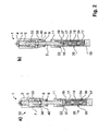
- FIG. 1 are two rotated by 90 degrees to each other schematic views of a damping device according to a first preferred embodiment of the invention in unamplified state shown.
- the damping device 1 has a length L1 in the unstretched state, which corresponds to the distance from the upper end of the head of the fastening means 4 to the lower end of the guide sleeve 10.
- the pipe sections are not shown in this figure.
- the illustrated embodiment of the damping device 1 according to the invention has a guide sleeve 10 which is rotatably mounted in a blind hole or an axial central cavity 20 of the lowermost tube section 25 of a pole tube 24 and in which an axle pin 2 engages with its lower free end.
- a spreading device 32 is shown above the guide sleeve, which is a spreading element 3, a in the sections of FIG. 2 visible inner member 33 and an inner cone 5 has.
- the axle pin 2 is provided at least at its upper end with an external thread and has a head 4 by means of a fastening means 4, preferably a screw, fixed axially.
- the head 4 forms the upper stop for the expansion element 3.
- the lower stop of the expansion element 3 forms in FIG. 1a a on the axle 2, for example, molded, screwed, placed, clamped or welded center piece 8. Below the middle piece 8 is in FIG.
- the expansion element 3 has at least one, but preferably two opposing axial recesses 6.
- this recess 6 engages within the expansion element 3 coaxially arranged inner element 33 with at least one axial rib 7, but preferably with two mutually opposite to the inner member 33 ribs 7 a.
- this recess 6 is not visible because the damping device against the FIG. 1a turned 90 degrees and is in the illustrated embodiment in the expansion element 3 at one of the recess 6 by 90 twisted position no further recess.
- the spreader is in the representations of FIGS. 1 and 2 in an unexpanded state.
- FIG. 1a is to be seen in the central region 10b of the substantially U-shaped guide sleeve 10 shown in the section elongated hole 12, which forms an upper stop 13 and a lower stop 14. Between these stops 13, 14 is a guide sleeve and at least partially radially engaging in the slot 12 is a the axle pin 2 at its lower end by passing transverse pin 15 is arranged.
- the transverse pin 15 is located in the representations of FIGS. 1 and 2 , ie at undamped or unattenuated floor 23 at the upper stop 13 of the slot 12 of the guide sleeve 10.
- On the guide sleeve 10 and the upper portion 10 a is a insert piece 11 is placed or attached.
- the axle pin 2 is with its lower end 37 in a receiving element 16, which is formed substantially cup-shaped and is mounted in the guide sleeve 10, added.
- the receiving element 16 thus forms an intermediate element between the compression spring device 35 and the axle 2,
- the in FIG. 2a transverse pin 15 shown perpendicular to the axis of the pole S protrudes from the outside inwards first the wall of the guide sleeve 10, then the axle 2 and then the opposite wall of the guide sleeve 10th
- the compression spring device is in FIGS. 2a and 2b as a series arrangement of three springs, wherein at both axial ends of a pressure coil spring 18 is arranged above and below each an elastomeric spring 17 is formed. Between the elastomeric spring 17 and the pressure coil spring 18, a substantially T-shaped pin 34 is arranged, which partially engages the pressure coil spring 18 and thus prevents penetration of the elastomeric spring 17 into the pressure coil spring 18. The disc-like region of the T-shaped pin defines the distance between the elastomer spring 17 and pressure coil spring 18th
- the centerpiece whose cut in FIGS. 2a and 2b is particularly well recognizable, preferably at its upper end both in the axial direction a circumferential nose 39 and in the radial direction a circumferential projection 40.
- the circumferential nose 39 serves to stop the middle piece 8 on the underside of the inner cone 5. The indentation of the middle piece resulting from the nose 39 allows the spreading element a certain axial play within narrow limits.
- the shortening of the length of the pole from the undamped to the damped state is approximately 5-15 mm, preferably 7-12 mm, more preferably 8-10 mm.
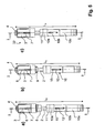
- FIG. 3 shows three alternative embodiments of damping devices 1 in the unbiased state, wherein the in FIG. 5a has shown damping device 1a no additional damping element 9.
- the length L2 of the uncompressed damping device 1a of FIG. 5a smaller than the length L1 of the uncompressed damping device 1 of FIG. 1
- the length L3 of the uncompressed damping device 1b of FIG. 5b is again smaller than the length L2 of the uncompressed damping device 1a
- the length L4 of the uncompressed damping device 1c is smaller than the length L3 of the uncompressed damping device 1b.
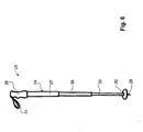
- FIG. 6 is a schematic view of a stick 23 is shown.
- the floor 23, is shown here only as an example as a ski pole.
- the floor 23 according to the invention can also be, for example, a trekking, hiking or Nordic walking pole or the like.
- the illustrated pole tube 24, according to this embodiment three pipe sections 25, 26, 27, wherein each two adjacent pipe sections 25, 26 and 26, 27 are telescopically relative to each other, resulting in a length adjustment of the stick 23 results.
- a pole tip 29 is arranged, which is optionally übercapt of a stick plate 30.
- the pole tip 29 may well be designed as a buffer with or without spikes.
- the lowermost tubular section 25 has the smallest diameter of the three illustrated tubular sections 25, 26, 27 forming the pole tube 24.
- the pole tube 24 consists of more than three pipe sections.
- the diameter of the uppermost pipe section 27 arranged immediately below the pole grip 28 is the pipe section with the largest diameter.
- the second lowest pipe section 26 has a larger diameter than the uppermost pipe section 27. This is, for example, to achieve an improved Swing behavior of the stick 23 conceivable.
- the tube sections, seen from top to bottom have decreasing diameters.
- Each pipe section 25, 26, 27 may also have different diameters in itself.
- the lower portion of a pipe section has a smaller diameter than the upper portion of the same pipe section.
- the pole grip 28 may optionally have a hand strap 31 attached thereto or a coupling mechanism for an attachable hand strap 31.
- pole tubes 23 are surrounded at the transition areas between two tube sections 25, 26 and 26, 27 by a collar.
- the damping device 1 is arranged at such a floor between the pipe sections indicated by the reference numerals 25 and 26, ie, the guide sleeve 10 is inserted at the upper end of the lowermost pipe section 25.
Description
Die vorliegende Erfindung betrifft einen Stock, wie beispielsweise einen Trekking-, Ski-, Wander-, oder Nordic-Walking-Stock, der einen Stockgriff, ein Stockrohr aus mindestens drei teleskopierbaren Rohrabschnitten, und eine Stockspitze aufweist. Jeweils zwei benachbarte Rohrabschnitte sind relativ zueinander verstellbar. Der erfindungsgemässe Stock weist eine Dämpfungsvorrichtung mit einer in einem ersten Rohrabschnitt drehfest gehaltenen Führungshülse auf, in der ein an einem zweiten Rohrabschnitt axial festgehaltener Achsstift geführt ist.The present invention relates to a pole, such as a trekking, skiing, hiking, or Nordic walking pole, which has a pole grip, a pole tube of at least three telescopic tubular sections, and a pole tip. Two adjacent pipe sections are adjustable relative to each other. The inventive floor has a damping device with a rotatably held in a first pipe section guide sleeve in which an axially held on a second pipe section axle pin is guided.
Aus dem Stand der Technik sind verschiedene Stöcke mit Stossdämpfer bekannt, so z.B. in der
Der Erfindung liegt demnach die Aufgabe zugrunde, einen konstruktiv einfachen Stock mit Dämpfungsvorrichtung zur Verfügung zu stellen, der ein möglichst kleines Gewicht und Packmass hat und ein möglichst gutes Schwungverhalten aufweist, wobei die Dämpfungsvorrichtung möglichst platzsparend untergebracht werden soll.The invention is therefore an object of the invention to provide a structurally simple floor with damping device available, which has the smallest possible weight and packing size and has the best possible swing behavior, the damping device should be accommodated as space-saving.
Die Aufgabe wird durch einen Stock nach Anspruch 1 gelöst, wie beispielsweise einen Trekking-, Ski-, Wander-, oder Nordic-Walking-Stock, mit Handgriff, Stockrohr und Stockspitze, welcher mindestens drei teleskopierbare Rohrabschnitte aufweist. Dabei sind jeweils zwei benachbarte Rohrabschnitte relativ zueinander verstellbar. Der erfindungsgemässe Stock weist eine Dämpfungsvorrichtung bzw. einen Stossdämpfer mit einer in einem ersten Rohrabschnitt drehfest gehaltenen Führungshülse und mit einer Druckfedervorrichtung auf, wobei in der Führungshülse ein an einem zweiten Rohrabschnitt axial festgehaltener Achsstift geführt ist. Dabei ist der erste Rohrabschnitt der unterste Rohrabschnitt und der zweite Rohrabschnitt der zweitunterste Rohrabschnitt des Stockrohrs.The object is achieved by a stick according to claim 1, such as a trekking, skiing, hiking, or Nordic walking stick, with handle, pole and stick tip, which has at least three telescoping pipe sections. In each case two adjacent pipe sections are adjustable relative to each other. The inventive floor has a damping device or a shock absorber with a rotatably held in a first pipe section guide sleeve and with a compression spring device, wherein in the guide sleeve an axially held on a second pipe section axle pin is guided. Here, the first pipe section of the bottom pipe section and the second pipe section of the second lowest pipe section of the pole tube.
Der Kern der Erfindung besteht somit darin, die Druckfedervorrichtung, welche sonst bei Stöcken mit drei Rohrabschnitten jeweils im mittleren Rohrabschnitt oder zwischen den zwei oberen Rohrabschnitten angeordnet ist, in den unteren Rohrabschnitt oder zwischen die beiden unteren Rohrabschnitte zu verlagern. Dabei weist der unterste Rohrabschnitt von den drei teleskopierbaren Rohrabschnitten den kleinsten Durchmesser auf und ist zugleich im teleskopierten Zustand bzw. im kleinsten Packmass der innerste Rohrabschnitt. Der Durchmesser des obersten Rohrabschnittes ist grösser als der Durchmesser des mittleren bzw. zweituntersten Rohrabschnittes und dieser wiederum ist grösser als der Durchmesser des untersten Rohrabschnittes. Beispielsweise ist bei Stöcken mit vier Rohrabschnitten vorzugsweise mindestens eine Druckfedervorrichtung im untersten der vier Rohrabschnitte angeordnet, wobei der unterste Rohrabschnitt gleichzeitig der innerste der vier Rohrabschnitte ist.The core of the invention is thus to shift the compression spring device, which is otherwise arranged in sticks with three pipe sections respectively in the central pipe section or between the two upper pipe sections, in the lower pipe section or between the two lower pipe sections. In this case, the lowest pipe section of the three telescoping pipe sections on the smallest diameter and is at the same time in the telescoped state or in the smallest packing size of the innermost pipe section. The diameter of the uppermost pipe section is greater than the diameter of the middle or second lowest pipe section and this in turn is greater than the diameter of the lowermost pipe section. For example, in sticks with four pipe sections, preferably at least one compression spring device is arranged in the lowest of the four pipe sections, wherein the lowermost pipe section is at the same time the innermost of the four pipe sections.
Alternativ und generell ist es bei einer Stockkonstruktion (z.B. mit drei telekopierbaren Abschnitten), bei welcher das oberste Rohr den geringsten Durchmesser aufweist, die Druckfedervorrichtung, wie sie hier beschrieben wird, im obersten Rohrabschnitt mit nach unten gerichteter Klemmvorrichtung anzuordnen, auch dann ergeben sich vorteilhaftes Schwungverhalten und minimales Packmass.Alternatively and generally, it is in a floor construction (eg, with three telescopic sections), in which the uppermost tube has the smallest diameter to arrange the compression spring device, as described here, in the uppermost pipe section with downward clamping device, then there are also beneficial Swing behavior and minimal packing size.
Durch die Verlagerung der Druckfedervorrichtung in den untersten Rohrabschnitt wird das Gewicht und auch die Baugrösse des Stockes verringert, da weniger Rohrmaterial nötig ist. Gleichzeitig wird somit der Schwerpunkt des Stockes weiter nach unten verlagert, was zu einem verbesserten Schwungverhalten des Stockes führt. Durch die Verlegung der Druckfedervorrichtung aus dem mittleren Rohrabschnitt heraus wird es nun möglich, die drei Rohrabschnitte im Wesentlichen vollständig ineinander zu teleskopieren, sodass die sich die Stocklänge bei Packgrösse um ca. zwei Drittel verringert.By the displacement of the compression spring device in the bottom tube section is The weight and the size of the stick reduced because less pipe material is needed. At the same time, therefore, the center of gravity of the stick is shifted further down, resulting in an improved swing behavior of the stick. By laying the compression spring device out of the middle pipe section out, it is now possible to telescope the three pipe sections substantially completely into one another, so that the length of the pipe is reduced by about two-thirds in pack size.
Der in der
Durch die Verlagerung der Federeinheit in das Unterteil, d.h. in den unteren bzw. inneren Rohrabschnitt wird der Platz frei, der vorher für den Einbauraum der Feder im Mittelteil, d.h. im mittleren Rohrabschnitt beansprucht wurde. Bei der erfindungsgemässen Anordnung der Druckfedervorrichtung im unteren und inneren von zwei Rohrabschnitten kann der Innenraum dieses Rohrabschnittes beliebig ausgenutzt werden, da dort in der Regel kein Längenverstellmechanismus angeordnet ist. Zusätzlich wird durch die erfindungsgemässe Verlagerung erreicht, dass der Stock ein kleineres Gewicht aufweist, da einige Zentimeter Rohr eingespart werden, welche vorher für den Einbauraum im mittleren Rohrabschnitt verwendet werden mussten. Insbesondere kann die Druckfedervorrichtung durch ihren Einbau im untersten Rohrabschnitt filigraner bzw. mit kleinerem Durchmesser ausgebildet werden, da weniger Material nötig ist, um den untersten bzw. innersten teleskopierbaren Rohrabschnitt, welcher somit auch den kleinsten Rohrdurchmesser aufweist, auszufüllen. Dies bringt somit auch eine Gewichtsverringerung der eingebauten Druckfedervorrichtung mit sich. Ausserdem ist es durch die erfindungsgemässe Konstruktion möglich, für Stöcke mit Stossdämpfern dieselbe Rohrlängen zu verwenden wie für Stöcke ohne Stossdämpfer, wobei die Mehrkosten der Anfertigung von Speziallängen wegfallen, welche aufgewendet werden müssen, wenn die Druckfedervorrichtung im mittleren Rohrabschnitt angeordnet ist, da dort ein längerer Rohrabschnitt nötig ist. Auch wird es nun möglich, dass alle drei teleskopierbaren Rohrabschnitte eines Stockrohrs dieselbe Länge aufweisen.By the displacement of the spring unit in the lower part, ie in the lower or inner pipe section, the space is free, which was previously claimed for the installation space of the spring in the middle part, ie in the middle pipe section. In the inventive arrangement of the compression spring device in the lower and inner of two pipe sections, the interior of this pipe section can be used arbitrarily, since there is usually no Längenverstellmechanismus arranged. In addition, it is achieved by the displacement according to the invention that the stick has a smaller weight, since several centimeters of pipe are saved, which previously had to be used for the installation space in the middle pipe section. In particular, the compression spring device can by their installation in the lowest Tube section filigree or are designed with a smaller diameter, since less material is necessary to fill the bottom or innermost telescoping tube section, which thus also has the smallest diameter tube. This also brings with it a weight reduction of the built-in compression spring device with it. Moreover, it is possible by the inventive construction, to use for poles with shock absorbers the same tube lengths as for poles without shock absorber, the additional costs of making special lengths are eliminated, which must be used when the compression spring device is arranged in the middle tube section, there a longer Pipe section is necessary. It is also possible that all three telescoping pipe sections of a pole tube have the same length.
Bei der oben genannten Ausführungsform der Erfindung weist der unterste Rohrabschnitt einen zentralen axialen Hohlraum bzw. ein Sackloch auf, in welches die Führungshülse eingelassen ist.In the above-mentioned embodiment of the invention, the lowermost pipe section has a central axial cavity or a blind hole, in which the guide sleeve is embedded.
Gemäss einer ersten bevorzugten Ausführungsform hat der unterste Rohrabschnitt einen kleineren Durchmesser als der zweitunterste Rohrabschnitt, wobei vorzugsweise zudem der zweitunterste Rohrabschnitt einen kleineren Durchmesser hat als der ihm benachbarte drittunterste Rohrabschnitt.According to a first preferred embodiment, the lowermost pipe section has a smaller diameter than the second lowermost pipe section, wherein preferably also the second lowermost pipe section has a smaller diameter than the third lowermost pipe section adjacent to it.
Die Druckfedervorrichtung ist gänzlich in der Führungshülse gelagert respektive angeordnet. Die Führungshülse ist vorzugsweise mindestens mit einem unteren Bereich und einem mittleren Bereich im untersten Rohrabschnitt gelagert. Dabei ist es von Vorteil, wenn die Führungshülse mit einem Anteil von ca. 60-90%, bevorzugt mit etwa 80% ihrer Länge im untersten Rohrteil gelagert ist.The compression spring device is mounted or arranged entirely in the guide sleeve. The guide sleeve is preferably mounted at least with a lower region and a central region in the lowermost tube section. It is advantageous if the guide sleeve is mounted in a proportion of about 60-90%, preferably about 80% of its length in the lowermost tube part.
Gemäss einer weiteren bevorzugten Ausführungsform der Erfindung weist die Druckfedervorrichtung mindestens eine Druckwendelfeder und/oder mindestens eine Elastomerfeder auf. Dabei sind verschiedene serielle oder parallele Anordnungen von Druckwendelfeder(n) und Elastomerfeder(n) möglich. Ein besonders gutes Dämpfungsverhalten wird erreicht, wenn die Druckfedervorrichtung in Reihenanordnung eine Druckwendelfeder und an deren beiden axialen Enden je eine Elastomerfeder aufweist. Eine Abschaltungsmöglichkeit der Druckfedervorrichtung oder eine Vorspannung der Federung ist denkbar. Zudem können in der Druckfedervorrichtung Federn mit unterschiedlichen Federcharakteristika, zum Beispiel aufgrund von unterschiedlicher Härte bzw. unterschiedlichen Federkonstanten vorgesehen sein. In Bezug auf die Eigenschaften der Druckfederanordnung wird der Gegenstand der
Das Stockrohr weist bevorzugterweise zwei, drei oder vier, insbesondere bevorzugt drei ineinander teleskopierbare Rohrabschnitte auf. Der unterste Rohrabschnitt des erfindungsgemässen Stockes nach einer weiteren bevorzugten Ausführungsform hat einen Durchmesser von 10-14 mm, bevorzugt 12 mm. Der zweitunterste Rohrabschnitt hat vorteilhafterweise einen Durchmesser von 12-16 mm, bevorzugt 14 mm, und der drittunterste Rohrabschnitt einen Durchmesser von 14-18 mm, bevorzugt 16 mm. Die erfindungsgemässe Konstruktion erlaubt es gemäss einer weiteren bevorzugten Ausführungsform, dass alle Rohrabschnitte gleich lang sind.The pole tube preferably has two, three or four, more preferably three telescoping tube sections. The lowermost tube section of the inventive stick according to a further preferred embodiment has a diameter of 10-14 mm, preferably 12 mm. The second lowermost pipe section advantageously has a diameter of 12-16 mm, preferably 14 mm, and the third lowermost pipe section has a diameter of 14-18 mm, preferably 16 mm. The construction according to the invention makes it possible, according to a further preferred embodiment, for all pipe sections to have the same length.
Oberhalb der Führungshülse kann koaxial zur Druckfedervorrichtung ein Mittelstück am Achsstift angeordnet sein. Dieses Mittelstück, welches vorzugsweise aus Kunststoff oder Metall besteht, kann beispielsweise auf den Achsstift aufgepresst aufgeschraubt oder aufgespritzt sein. Es kann gleichzeitig als Anschlag für eine allfällig oberhalb der Druckfedervorrichtung angeordnete Verstellmechanik dienen und gleichzeitig als Blockiersicherung dienen. Es kann aber auch beispielsweise die Aufgabe eines Abstandhalters oder Anschlags für Rohrabschnitte erfüllen.Above the guide sleeve can be arranged coaxially to the compression spring device a center piece on the axle. This middle piece, which preferably consists of plastic or metal, can for example be screwed or sprayed onto the axle pin. It can simultaneously serve as a stop for any adjustment mechanism arranged above the compression spring device and at the same time serve as a blocking safeguard. But it can also meet, for example, the task of a spacer or stop for pipe sections.
Alternativ oder zusätzlich zum Mittelstück kann oberhalb der Führungshülse ein zusätzliches Dämpfungselement, vorzugsweise ein elastischer Ring, insbesondere bevorzugt ein Gummiring oder ein O-Ring aus elastischem Material, am Achsstift zur Druckfedervorrichtung angeordnet sein. Ist ein Mittelstück vorhanden, so ist das zusätzliche Dämpfungselement vorzugsweise unterhalb des Mittelstücks und angrenzend an dieses angeordnet. Der elastische Ring ist für die Funktion des Federsystems zwar nicht zwingend erforderlich. Dieses zusätzliche Dämpfungselement hat aber den Zweck der geräuschmindernden Endlagendämpfung des Stocks. Ohne ein solches Dämpfungselement, könnte in gestauchter Position des Stocks beim Aufeinandertreffen der z.B. aus Metall ausgebildeten Teile im Übergangsbereich zwischen zwei Rohrabschnitten, beispielsweise des Einlagestücks am untersten Rohr auf das Mittelstück, ein störendes Geräusch auftreten.Alternatively or in addition to the middle piece, an additional damping element, preferably an elastic ring, in particular preferably a rubber ring or an O-ring of elastic material, may be arranged on the axle pin to the compression spring device above the guide sleeve. If there is a center piece, that is additional damping element preferably arranged below the middle piece and adjacent to this. Although the elastic ring is not mandatory for the function of the spring system. However, this additional damping element has the purpose of noise-reducing cushioning of the floor. Without such a damping element, could occur in compressed position of the stick at the meeting of eg formed of metal parts in the transition region between two pipe sections, for example, the insert piece on the bottom pipe to the center piece, a disturbing noise.
Vorzugsweise weist die Führungshülse zwischen einem oberen Bereich und einem unteren Bereich einen Anschlag, vorzugsweise einen umlaufenden Absatz auf, an welchem der unterste Rohrabschnitt mit seiner oberen Kante anliegt. Denkbar ist, dass der obere, mittlere und untere Bereich der Führungshülse je im Wesentlichen einen Drittel der Länge der Führungshülse ausmachen, wobei es aber bevorzugt ist, wenn der obere Bereich, welcher vorzugsweise aus dem untersten Rohr herausragt, kleiner ist als der mittlere und der untere Bereich. Der obere Bereich weist an seiner unteren Kante vorzugsweise einen umlaufenden Absatz auf, an welchem der unterste Rohrabschnitt mit seiner oberen Kante anliegen kann. Dieser Absatz kann entweder einstückig angeformt oder am oberen Bereich der Führungshülse befestigt sein.Preferably, the guide sleeve between an upper portion and a lower portion of a stop, preferably a circumferential shoulder, on which the bottom tube portion rests with its upper edge. It is conceivable that the upper, middle and lower regions of the guide sleeve each make up substantially one third of the length of the guide sleeve, but it is preferred if the upper region, which preferably protrudes from the lowermost tube, is smaller than the middle one and lower area. The upper region preferably has at its lower edge a circumferential shoulder on which the lowermost tube section can rest with its upper edge. This paragraph can either be integrally formed or attached to the upper portion of the guide sleeve.
Nach einer weiteren bevorzugten Ausführungsform der Erfindung weist die Führungshülse, vorzugsweise in ihrem mittleren Bereich, mindestens ein axiales Langloch, vorzugsweise aber zwei einander gegenüberliegende Langlöcher auf. Dabei ist ein Querstift senkrecht zur Stockachse in der Führungshülse, vorzugsweise oberhalb der Druckfedervorrichtung und wenigstens teilweise im Langloch angeordnet, sodass er zwischen einem oberen Anschlag und einem unteren Anschlag axial im Langloch beweglich ist. Zusätzlich ist es möglich und bevorzugt, dass der Querstift das untere Ende des Achsstiftes durchragt.According to a further preferred embodiment of the invention, the guide sleeve, preferably in its central region, at least one axial slot, but preferably two opposing slots. In this case, a cross pin is perpendicular to the pole axis in the guide sleeve, preferably arranged above the compression spring device and at least partially in the slot, so that it is axially movable in the slot between an upper stop and a lower stop. In addition, it is possible and preferred that the transverse pin extends through the lower end of the axle pin.
Koaxial mit der Druckfedervorrichtung und bevorzugt oberhalb von der Druckfedervorrichtung ist mindestens eine Spreizvorrichtung am Achsstift angeordnet ist. Im Hinblick auf die Spreizvorrichtung wird der Gegenstand der
Der Innenkonus ist nach einer weiteren erfindungsgemässen bevorzugten Ausführungsform zweiteilig ausgebildet. Er kann aber auch einteilig ausgebildet sein und einen durchgehenden, oben und unten offenen axialen Schlitz aufweisen. Dadurch kann erreicht werden, dass beispielsweise bei Abnützungserscheinungen der Innenkonus auswechselbar ist, da er nicht nur axial auf den Achsstift aufsetzbar ist, sondern auch bei bereits befestigtem Befestigungsmittel in radialer Richtung auf den Achsstift aufklemmbar ist. Zu diesem Zweck kann der Innenkonus beispielsweise ein Filmscharnier oder ein anderes Verbindungsmittel für die beiden Konushälften aufweisen. Beim Vorhandensein einer Spreizvorrichtung kann das Mittelstück oder das zusätzliche elastische Dämpfungselement, oder aber, falls diese beiden Teile nicht vorhanden sind, das obere Ende des Einlagestücks oder der Führungshülse einen Anschlag für das Spreizelement bieten. Für die nachträgliche Montage des Innenkonus ist es nebst einer geschlitzten oder geteilten Ausführungsförm auch denkbar, dass der Innenkonus über Filmscharniere klappbar ausgebildet ist, um über den fest verbundenen Schraubenkopf oder den Kopf eines anderen Befestigungsmittels zu gelangen.The inner cone is formed in two parts according to another preferred embodiment of the invention. But it can also be integrally formed and have a continuous, open top and bottom axial slot. It can thereby be achieved that, for example, in wear phenomena of the inner cone is replaceable, since it is not only axially mounted on the axle pin, but also with already fastened fastener in the radial direction can be clamped onto the axle pin. For this purpose, the inner cone, for example, have a film hinge or another connecting means for the two conical halves. In the presence of a spreading the center piece or the additional elastic damping element, or if these two parts are not present, the upper end of the insert or the guide sleeve provide a stop for the expansion element. For the subsequent assembly of the inner cone, together with a slotted or split embodiment, it is also conceivable for the inner cone to be foldable via film hinges in order to reach over the firmly connected screw head or the head of another fastening means.
Bei einem erfindungsgemässen Stock mit Spreizvorrichtung ist es möglich, dass der Achsstift in einem oberen Bereich, vorzugsweise lediglich in dem Bereich, auf dem die Spreizvorrichtung montiert ist, ein Gewinde aufweist. Der Kopf des Achsstiftes ist vorzugsweise fest angeformt. Er kann aber auch lösbar am Achsstift befestigt sein, beispielsweise mittels einer aufgesetzten Stoppmutter oder Schraube. Vorzugsweise wird dieser separat aufgesetzte abschlussbildende Kopf des Achsstiftes mit einer hoch belastbaren Verbindungsmethode fixiert, welche den Effekt eines fix angeformten Kopfes nachträglich herstellt, um eine belastbare Anlageschulter für das Spreizelement zur Verfügung zu stellen. Ist der Kopf fest angeformt, d.h. ist der Achsstift einstückig mit dem Kopf ausgebildet, ist es denkbar, dass der Innenkonus bei der Montage von unten auf den Achsstift aufgeschraubt wird, bevor der Achsstift in die Führungshülse eingeführt wird. Bei einem separat aufsetzbaren Kopf lässt sich auch ein nichtgeschlitzter oder geteilter Innenkonus später noch auswechseln, indem der Kopf abmontiert wird und der Innenkonus über das dann freie obere Ende montiert wird.In an inventive pole with spreading device, it is possible that the axle pin has a thread in an upper region, preferably only in the region on which the spreading device is mounted. The head of the axle pin is preferably firmly formed. But it can also be releasably secured to the axle, for example by means of an attached stop nut or screw. Preferably, this separately patched end-forming head of the axle pin is fixed with a high-load connection method, which subsequently produces the effect of a fixed molded head to provide a resilient contact shoulder for the expansion element available. If the head is firmly formed, i. If the axle pin is integrally formed with the head, it is conceivable that the inner cone is screwed from below onto the axle pin during assembly, before the axle pin is inserted into the guide sleeve. If a head can be placed separately, a non-slotted or split inner cone can also be replaced later by removing the head and installing the inner cone over the then free upper end.
Ist eine Druckwendelfeder angeordnet, so weist die Druckfedervorrichtung vorzugsweise mindestens ein Zapfen auf, welcher in ein Ende der Druckwendelfeder hineinragt und einen Vorsprung aufweist. Dabei ist es bei einer Reihenanordnung von Druckwendel- und Elastomerfeder von Vorteil, wenn der Vorsprung des Zapfens unmittelbar an die Elastomerfeder grenzt, wobei verhindert wird, dass die Elastomerfeder in die Druckwendelfeder eindringt. In einem solchen Fall ist gewissermassen der Zapfen zwischen Druckwendel- und Elastomerfeder angeordnet, wobei die beiden Federtypen höchstens durch einen kleinen Bereich des Zapfenvorsprungs axial beabstandet sind.If a compression coil spring is arranged, then the compression spring device preferably has at least one pin, which projects into one end of the compression coil spring and has a projection. It is advantageous in a series arrangement of Druckwendel- and elastomeric spring when the projection of the pin directly adjacent to the elastomeric spring, wherein it is prevented that the elastomeric spring penetrates into the compression coil spring. In such a case, the pin is arranged between Druckwendel- and elastomeric spring, so to speak, wherein the two types of spring are axially spaced at most by a small portion of the pin projection.
Bei der Montage wird zuerst die Druckfedervorrichtung in die Führungshülse eingesetzt. Auf diese Druckfedervorrichtung wird vorteilhafterweise ein Aufnahmeelement aufgesetzt, das bevorzugt im Wesentlichen topfförmig nach oben offen ausgebildet ist, und in welches dann der Achsstift einsetzbar ist. Anschliessend ist vorzugsweise ein Einlagestück auf die Führungshülse aufsetzbar, welches teilweise axial in die Führungshülse eingreift und ebenfalls eine zentrale Ausnehmung zur Aufnahme des Achsstifts aufweist. Das Einlagestück weist vorteilhafterweise an seinem in die Führungshülse hineinragenden Abschnitt mindestens eine, bevorzugt zwei Nasen oder eine umlaufende Nase auf, welche in korrespondierende Ausnehmungen bzw. mindestens einen Hinterschnitt in der Führungshülse selbsteinrasten. Um den Querstift durch die Führungshülse und in das Langloch, bzw. bevorzugt die beiden einander gegenüberliegenden Langlöcher im untersten Rohrabschnitt einführen zu können, kann Kraft von oben auf den Achsstift ausgeübt werden, bis die Durchstossöffnung am unteren Ende des Achsstiftes in das Langloch zu liegen kommt, sodass der Querstift durch das Langloch und die Durchstossöffnung des Achsstiftes sowie das vorzugsweise vorhandene gegenüberliegende zweite Langloch eingeschoben werden kann. Somit kann es sein, dass die Druckfedervorrichtung auch in der nicht gestauchten Position des Stockes leicht vorgespannt ist. Der Querstift verhindert gleichzeitig ein Ausreissen der Druckfeder nach oben und erlaubt eine axiale Bewegbarkeit der Druckfedervorrichtung innerhalb des Langlochs. Anschliessend an die Einsetzung des Querstiftes kann die Führungshülse in das Sackloch des untersten Rohrabschnittes eingesetzt werden.During assembly, the compression spring device is first inserted into the guide sleeve. In this compression spring device, a receiving element is advantageously placed, which is preferably formed substantially cup-shaped upwardly open, and in which then the axle is inserted. Subsequently, preferably, an insert piece can be placed on the guide sleeve, which partially engages axially in the guide sleeve and also has a central recess for receiving the axle pin. The insert advantageously has at its in the guide sleeve projecting portion at least one, preferably two lugs or a circumferential nose, which self-engage in corresponding recesses or at least one undercut in the guide sleeve. To the cross pin through the guide sleeve and into the slot, or preferably to introduce the two opposite slots in the bottom tube section, force can be exerted from above on the axle until the piercing at the bottom of the Achsstiftes comes to rest in the slot , So that the transverse pin can be inserted through the slot and the piercing opening of the axle pin and the preferably present opposite second slot. Thus, it may be that the compression spring device is slightly biased even in the non-compressed position of the stick. At the same time, the transverse pin prevents the compression spring from tearing upwards and permits axial mobility of the pressure spring device within the elongated hole. Subsequent to the insertion of the transverse pin, the guide sleeve can be inserted into the blind hole of the lowermost tube section.
Des Weiteren ist es möglich, dass der Achsstift zweiteilig ausgebildet und dass die beiden Teile über ein Verbindungsteil verbunden sind. Eine einteilige Konstruktion des Achsstifts ist jedoch bevorzugt, da sie eine vereinfachte Bauweise ermöglichen. Der einteilige Achsstift ist in einem solchen Fall durchgängig ausgebildet. Der Achsstift weist vorzugsweise einen Durchmesser von 0.3-1 cm, vorzugsweise zwischen 0.4 und 0.7 cm auf.Furthermore, it is possible that the axle pin formed in two parts and that the two parts are connected via a connecting part. However, a one-piece construction of the axle pin is preferred because it allows a simplified construction. The one-piece axle pin is formed continuously in such a case. The axle pin preferably has a diameter of 0.3-1 cm, preferably between 0.4 and 0.7 cm.
Weitere bevorzugte Ausführungsformen der vorliegenden Erfindung sind in den abhängigen Ansprüchen beschrieben.Further preferred embodiments of the present invention are described in the dependent claims.
Die Erfindung soll nachfolgend anhand von Ausführungsbeispielen im Zusammenhang mit den Zeichnungen näher erläutert werden. Es zeigen:
- Fig. 1
- zwei schematische Ansichten einer Dämpfungsvorrichtung gemäss einer ersten bevorzugten Ausführungsform der Erfindung in ungestauchtem Zustand, wobei
Fig. 1a) und Fig. 1b ) die Dämpfungsvorrichtung von zwei um 90 Grad verdrehten Ansichten zeigen; und - Fig. 2
- zwei axiale Schnitte durch die Dämpfungsvorrichtung von
Figur 1 , wobei inFig. 2a ) ein Schnitt durch die Schnittachse A-A und inFig. 2b ein Schnitt durch die Schnittachse B-B dargestellt sind; und - Fig. 3
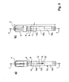
- zwei schematische Ansichten einer Dämpfungsvorrichtung gemäss einer ersten bevorzugten Ausführungsform der Erfindung in gestauchtem Zustand, wobei
Fig. 3a) und Fig. 3b ) die Dämpfungsvorrichtung von zwei um 90 Grad in Umfangsrichtung verdrehten Ansichten zeigen; und - Fig. 4
- zwei axiale Schnitte durch die
Dämpfungsvorrichtung von Figur 3 , wobei inFig. 4a ) ein Schnitt durch die Schnittachse C-C und inFig. 4b ein Schnitt durch die Schnittachse D-D dargestellt sind; und - Fig. 5
- drei alternative Ausführungsbeispiele einer erfindungsgemässen Dämpfungseinrichtung in ungestauchtem Zustand in einer schematischen Ansicht, wobei
Fig. 5a ) eine Dämpfungsvorrichtung ohne Mittelstück, dieFig. 5b ) eine Dämpfungsvorrichtung ohne Gummiring, undFig. 5c ) eine Dämpfungseinrichtung ohne Mittelstück und Gummiring darstellt; und - Fig. 6
- schematische Darstellung eines Stocks mit drei teleskopierbaren Rohrabschnitten.
- Fig. 1
- two schematic views of a damping device according to a first preferred embodiment of the invention in an unstretched state, wherein
Fig. 1a) and Fig. 1b ) The damping device of two by 90 degrees show twisted views; and - Fig. 2
- two axial sections through the damping device of
FIG. 1 , where inFig. 2a ) a section through the section axis AA and inFig. 2b a section through the sectional axis BB are shown; and - Fig. 3
- two schematic views of a damping device according to a first preferred embodiment of the invention in a compressed state, wherein
Fig. 3a) and Fig. 3b ) show the damping device of two views rotated by 90 degrees in the circumferential direction; and - Fig. 4
- two axial sections through the damping device of
FIG. 3 , where inFig. 4a ) a section through the cutting axis CC and inFig. 4b a section through the cutting axis DD are shown; and - Fig. 5
- three alternative embodiments of a damping device according to the invention in undamped state in a schematic view, wherein
Fig. 5a ) a damping device without center piece, theFig. 5b ) a damping device without rubber ring, andFig. 5c ) represents a damper without center piece and rubber ring; and - Fig. 6
- schematic representation of a stick with three telescopic pipe sections.
In der Folge sollen Ausführungsbeispiele zur Illustration der oben beschriebenen Erfindung dargestellt werden. Es ist dabei hervorzuheben, dass diese Ausführungsbeispiele zur Erläuterung und zur Dokumentation der Durchführbarkeit der Erfindung hinzugezogen werden sollen, nicht aber zur Einschränkung des generellen Erfindungsgedankens, wie er in den angehängten Ansprüchen definiert ist. Änderungen und Variationen des Ausführungsbeispiels, wie es in der Folge diskutiert wird, sind dem Fachmann zugänglich und ebenfalls von den Ansprüchen umfasst.In the following, exemplary embodiments will be illustrated to illustrate the invention described above. It is to be understood that these embodiments are to be considered as illustrative and for the purpose of describing the feasibility of the invention, and not for the purpose of limiting the scope of the invention as defined in the appended claims. Changes and variations of the embodiment, as discussed below, will be apparent to those skilled in the art and also covered by the claims.
In
Das Spreizelement 3 weist mindestens eine, bevorzugt aber zwei einander gegenüberliegende axiale Ausnehmungen 6 auf. In diese Ausnehmung 6 greift das innerhalb des Spreizelements 3 koaxial angeordnete Innenelement 33 mit mindestens einer axialen Rippe 7, bevorzugt aber mit zwei einander am Innenelement 33 gegenüberliegenden Rippen 7 ein. In
In
In den
Die Druckfedervorrichtung ist in
Das Mittelstück, dessen Schnitt in
In
In
In
Gemäss der Darstellung von
- 11
- Dämpfungsvorrichtung, StossdämpferDamping device, shock absorber
- 1a1a
- Dämpfungsvorrichtung ohne 9Damping device without 9
- 1b1b
- Dämpfungsvorrichtung ohne 8Damping device without 8
- 1c1c
- Dämpfungsvorrichtung ohne 8 und 9Damping device without 8 and 9
- 22
- Achsstiftaxle pin
- 33
- Spreizelementspreader
- 44
- Kopf von 2Head of 2
- 55
- Innenkonusinner cone
- 66
- axiale Ausnehmung von 3axial recess of 3
- 77
- axiale Rippe von 5axial rib of 5
- 88th
- Mittelstückcenterpiece
- 99
- zusätzliches Dämpfungselement, Gummiringadditional damping element, rubber ring
- 1010
- Führungshülseguide sleeve
- 10a10a
- oberer Bereich von 10upper range of 10
- 10b10b
- mittlerer Bereich von 10middle range of 10
- 10c10c
- unterer Bereich von 10lower range of 10
- 1111
- Einlagestückinsert piece
- 1212
- axiales Langloch von 10axial slot of 10
- 1313
- erster Anschlag von 12first stop of 12
- 1414
- zweiter Anschlag von 12second stop of 12
- 1515
- Querstiftcross pin
- 1616
- Aufnahmeelement für 2Receiving element for 2
- 1717
- Elastomerfederelastomer spring
- 1818
- DruckwendelfederCoil compression spring
- 1919
- Öffnung in 2Opening in 2
- 2020
- axialer Hohlraum, Sackloch in 10axial cavity, blind hole in 10
- 2121
- axiale Aussparung, Rilleaxial recess, groove
- 2222
- Anschlag, Anlageschulter in 10aStop, contact shoulder in 10a
- 2323
- Stockfloor
- 2424
- Stockrohrstock pipe
- 2525
- unterster Rohrabschnittbottom pipe section
- 2626
- zweitunterster bzw. mittlerer Rohrabschnittsecond bottom or middle pipe section
- 2727
- drittunterster bzw. oberster Rohrabschnittthird lowest or highest pipe section
- 2828
- Stockgriffstick handle
- 2929
- Stockspitzestock tip
- 3030
- Stocktellerstock plate
- 3131
- Handschlaufehand strap
- 3232
- Spreizvorrichtungspreading
- 3333
- Innenelementinner element
- 3434
- Zapfenspigot
- 3535
- DruckfedervorrichtungSpring device
- 3636
- Vorsprung von 34Lead of 34
- 3737
- Nase von 11Nose of 11
- 3838
- unteres Ende von 2lower end of 2
- 3939
- umlaufende Nase von 8circumferential nose of 8
- 4040
- umlaufender Vorsprung von 8circumferential lead of 8
- L1L1
- ungestauchte Länge von 1uncompressed length of 1
- L1'L1 '
- gestauchte Länge von 1compressed length of 1
- L2L2
- ungestauchte Länge von 1 auncompressed length of 1 a
- L3L3
- ungestauchte Länge von 1buncompressed length of 1b
- L4L4
- ungestauchte Länge von 1cuncompressed length of 1c
- SS
- Stockachsepole axis
Claims (14)
- A pole (23), for example a trekking, ski, hiking or Nordic walking pole, having at least three telescopic tube portions of a pole shaft (24) provided with a pole grip (28) and pole tip (29), wherein in each case two adjacent tube portions can be adjusted relative to one another, having a damping device (1) with a guide sleeve (10) retained in a rotationally fixed manner in a first tube portion and with a compression-spring device (35), wherein an axial pin (2) secured axially in a second tube portion is guided in the guide sleeve (10), wherein
the first tube portion is the lowermost tube portion (25) and the second tube portion is the second-from-the-bottom tube portion (26) characterized in that the entire compression-spring device (35) is mounted in the guide sleeve (10). - The pole (23) as claimed in claim 1, characterized in that the lowermost tube portion (25) has a smaller diameter than the second-from-the-bottom tube portion (26), wherein preferably the second-from-the-bottom tube portion (26) has a smaller diameter than the third-from-the-bottom tube portion (27) adjacent to it.
- The pole (23) as claimed in one of the preceding claims, characterized in that the guide sleeve (10) at least has a bottom region (10c) and a central region (10b) mounted in the lowermost tube portion (25).
- The pole (23) as claimed in one of the preceding claims, characterized in that the compression-spring device (35) has at least one helical compression spring (18) and/or at least one elastomer spring (17).
- The pole (23) as claimed in one of the preceding claims, characterized in that the compression-spring device (35) has, in a series arrangement, a helical compression spring (18) and an elastomer spring (17) at each of the two axial ends thereof.
- The pole (23) as claimed in one of the preceding claims, characterized in that the pole shaft (24) has three or four tube portions (25, 26, 27).
- The pole (23) as claimed in one of the preceding claims, characterized in that a central piece (8) is arranged on the axial pin (2) coaxially above the guide sleeve (10).
- The pole (23) as claimed in one of the preceding claims, characterized in that, above the guide sleeve (10), an additional damping element (9), preferably an elastic ring, in particular preferably a rubber ring, is arranged on the axial pin (2) coaxially in relation to the compression-spring device (35).
- The pole (23) as claimed in one of the preceding claims, characterized in that the guide sleeve (10), preferably between a top region (10a) and a bottom region (10b), has a stop (22), preferably an encircling shoulder, against which the lowermost tube portion (25) butts by way of its top edge.
- The pole (23) as claimed in one of the preceding claims, characterized in that the guide sleeve (10), preferably in its central region (10b), has at least one axial slot (12), preferably two mutually opposite slots (12), wherein a transverse pin (15) is arranged perpendicularly to the pole axis (S) in the guide sleeve (10), preferably above the compression-spring device (35) and at least in part in the slot (12), in which case it can be moved axially in the slot (12) between a top stop (13) and a bottom stop (14), wherein preferably the transverse pin (15) projects through the bottom end of the axial pin (2).
- The pole (23) as claimed in one of the preceding claims, characterized in that the lowermost tube portion (25) has a diameter of 10-14 mm, preferably 12 mm, in that the second-from-the-bottom tube portion (26) has a diameter of 12-16 mm, preferably 14 mm, and in that the third-from-the-bottom tube portion has a diameter of 14-18 mm, preferably 16 mm, wherein preferably all the tube portions (25, 26, 27) are of equal length.
- The pole (23) as claimed in one of the preceding claims, characterized in that at least one spreading device (32) is arranged on the axial pin (2), coaxially with the compression-spring device (35) and preferably above the compression-spring device (35), wherein preferably the lowermost tube portion (25), which has the damping device (1), can be clamped axially in the second-from-the-bottom tube portion (26) by way of the spreading device (32), and in that the spreading device (32) has a spreading element (3), which can be forced apart radially and is provided with an inner cone (5), and an inner element (33), which is provided with an outer cone running in the opposite direction and is accommodated such that it can be displaced axially in the spreading element (3), and an axially directed adjusting screw (4), which is retained in a rotationally fixed manner on the lowermost tube portion (25) and is operatively connected to an internally threaded bore in the inner element (33), wherein the inner cone (5) of the spreading element (3) runs such that it opens in the direction of the lowermost tube portion, and that the spreading element (3) is retained such that it can be moved axially, preferably within narrow limits, between a bottom stop on an inner tube, preferably on the guide sleeve (10), in particular preferably on an insert piece (11) anchored in the guide sleeve (10) at one end, or on a central piece (8) arranged coaxially above the guide sleeve, and a top stop at the free end of the adjusting screw (4).
- The pole (23) as claimed in either of claims 11 and 12, characterized in that the inner cone (5) is formed in one or two parts and has at least one axial slot, which is open at the top and bottom, passing through it.
- The pole (23) as claimed in claim 4, characterized in that the compression-spring device (35) has at least one stub (34) which projects into one end of the helical compression spring (18) and has a protrusion (36).
Applications Claiming Priority (2)
| Application Number | Priority Date | Filing Date | Title |
|---|---|---|---|
| CH10712007 | 2007-07-03 | ||
| PCT/CH2008/000283 WO2009003298A1 (en) | 2007-07-03 | 2008-06-24 | Stick with a shock absorber |
Publications (2)
| Publication Number | Publication Date |
|---|---|
| EP2160115A1 EP2160115A1 (en) | 2010-03-10 |
| EP2160115B1 true EP2160115B1 (en) | 2014-06-18 |
Family
ID=38606698
Family Applications (1)
| Application Number | Title | Priority Date | Filing Date |
|---|---|---|---|
| EP08757276.4A Active EP2160115B1 (en) | 2007-07-03 | 2008-06-24 | Stick with a shock absorber |
Country Status (5)
| Country | Link |
|---|---|
| US (2) | US8474471B2 (en) |
| EP (1) | EP2160115B1 (en) |
| JP (1) | JP5289434B2 (en) |
| CN (1) | CN101686743B (en) |
| WO (1) | WO2009003298A1 (en) |
Families Citing this family (17)
| Publication number | Priority date | Publication date | Assignee | Title |
|---|---|---|---|---|
| US9254237B2 (en) * | 2009-10-23 | 2016-02-09 | Auckland Mobility Devices Limited | Shock absorber insert for a walking aid |
| CH702967A1 (en) * | 2010-04-14 | 2011-10-14 | Lekisport Ag | Nordic Walking Stick with buffer. |
| EP2579741B1 (en) | 2010-06-14 | 2018-05-02 | Lekisport AG | Pole having a shock absorber |
| US8528577B2 (en) * | 2010-07-13 | 2013-09-10 | Easton Technical Products, Inc. | Shock absorbing system for trekking poles |
| US20120049502A1 (en) * | 2010-09-01 | 2012-03-01 | Jose Ascunce | Telescopping Paddle for Skateboards |
| KR101218482B1 (en) * | 2011-05-13 | 2013-01-04 | 라제건 | Rotating Type Stick |
| CN102349730A (en) * | 2011-07-29 | 2012-02-15 | 苏州展华纺织有限公司 | Novel walking stick for blind persons |
| JP2013096578A (en) * | 2011-10-28 | 2013-05-20 | K-2 Corp | Collapsible pole assembly |
| US8479755B2 (en) * | 2011-11-18 | 2013-07-09 | Gentry Way Co., Ltd. | Ambulatory aid |
| JP2015171452A (en) * | 2014-03-12 | 2015-10-01 | 真紀子 浜元 | Walking aid |
| TWM489528U (en) * | 2014-06-25 | 2014-11-11 | Valor Enterprise Co Ltd | Telescopically adjusting structure of cane |
| US10646012B2 (en) * | 2015-02-13 | 2020-05-12 | Lekisport Ag | Pole having a tip spring mechanism |
| CN106901467B (en) * | 2017-03-30 | 2018-11-06 | 嘉兴日雅光电有限公司 | A kind of handle grip device of folded umbrella |
| US10744051B2 (en) | 2017-11-10 | 2020-08-18 | Carolyn Virgo | Mobility device |
| CN108499413A (en) * | 2018-06-15 | 2018-09-07 | 浙江乐匠新材料科技有限公司 | A kind of water paint production paint mixing tank |
| USD894794S1 (en) | 2018-10-12 | 2020-09-01 | Carolyn Virgo | Mobility aid |
| CN110755823A (en) * | 2019-11-22 | 2020-02-07 | 宁海兴达旅游用品有限公司 | Foot holds in palm subassembly and damper of pole cane thereof |
Family Cites Families (17)
| Publication number | Priority date | Publication date | Assignee | Title |
|---|---|---|---|---|
| BE468340A (en) | 1944-12-28 | |||
| GB636739A (en) | 1947-01-03 | 1950-05-03 | Gunnar Tveten | Improvements in or relating to extensible ski sticks |
| AT397355B (en) | 1989-02-21 | 1994-03-25 | Lekisport Ag | LENGTH ADJUSTABLE STICK |
| IT1295519B1 (en) | 1997-09-29 | 1999-05-12 | Gabel Srl | CUSHIONING DEVICE FOR HIKING, WALKING SKI POLES AND CRUTCHES AND SIMILAR |
| DE29813601U1 (en) | 1998-07-30 | 1999-12-16 | Lenhart Klaus | Trekking pole with shock absorber |
| JP3920512B2 (en) * | 1999-11-15 | 2007-05-30 | アイワ産業株式会社 | Cane |
| GB2354939B (en) * | 2000-11-06 | 2001-09-05 | Thomas Francis Mcgrath | Walking aid |
| JP3833893B2 (en) * | 2000-12-28 | 2006-10-18 | アイワ産業株式会社 | Cane |
| US6595226B2 (en) * | 2001-05-16 | 2003-07-22 | Crystal Industrial Co., Ltd. | Telescoping walking stick |
| DE20117146U1 (en) | 2001-10-18 | 2003-02-27 | Lenhart Klaus | Trekking pole with shock absorber |
| DE20207554U1 (en) * | 2002-05-08 | 2003-10-09 | Lenhart Klaus | Length-adjustable tube, especially for sticks |
| CN2621471Y (en) * | 2003-04-16 | 2004-06-30 | 田万植 | Telescopic walking stick |
| DE20318642U1 (en) | 2003-12-03 | 2004-02-26 | Smartline International Co., Ltd., Nan Tou | Telescopic walking stick, comprising spring supported shock absorbing units inserted between segments |
| AT7045U1 (en) * | 2003-12-15 | 2004-09-27 | Komperdell Sportartikel Gmbh | DAMPING DEVICE |
| DE102004016668A1 (en) | 2004-04-05 | 2005-10-20 | Peter Kuelzer | Telescopic device, in particular trekking or hiking stick |
| CN2782076Y (en) * | 2005-01-24 | 2006-05-24 | 陈高山 | Anti-falling device of telescopic walking stick |
| CN2840755Y (en) * | 2005-10-17 | 2006-11-29 | 何冬生 | Lighting walking stick |
-
2008
- 2008-06-24 WO PCT/CH2008/000283 patent/WO2009003298A1/en active Application Filing
- 2008-06-24 JP JP2010513599A patent/JP5289434B2/en not_active Expired - Fee Related
- 2008-06-24 US US12/666,579 patent/US8474471B2/en active Active
- 2008-06-24 CN CN200880023171.9A patent/CN101686743B/en active Active
- 2008-06-24 EP EP08757276.4A patent/EP2160115B1/en active Active
-
2013
- 2013-05-15 US US13/894,537 patent/US20130247947A1/en not_active Abandoned
Also Published As
| Publication number | Publication date |
|---|---|
| CN101686743B (en) | 2011-08-10 |
| US8474471B2 (en) | 2013-07-02 |
| US20100170548A1 (en) | 2010-07-08 |
| CN101686743A (en) | 2010-03-31 |
| JP2010531681A (en) | 2010-09-30 |
| US20130247947A1 (en) | 2013-09-26 |
| EP2160115A1 (en) | 2010-03-10 |
| JP5289434B2 (en) | 2013-09-11 |
| WO2009003298A1 (en) | 2009-01-08 |
Similar Documents
| Publication | Publication Date | Title |
|---|---|---|
| EP2160115B1 (en) | Stick with a shock absorber | |
| EP1694971B1 (en) | Clamp device for telescopic tubes inserted one in the other | |
| EP2874717B1 (en) | Length adjustable tube, in particular for sticks | |
| EP2066195B1 (en) | Nordic walking pole with rubber buffer | |
| DE19717937A1 (en) | Braking and damping element for moving furniture parts | |
| EP3128867A1 (en) | Folding pole having a tubular sleeve | |
| EP1435805A1 (en) | Trekking stick comprising a shock absorber | |
| EP2807320A1 (en) | Pull-out device for at least two pull-out furniture parts | |
| EP2232096A1 (en) | Suspension strut having screw pot | |
| EP2579741B1 (en) | Pole having a shock absorber | |
| AT11499U1 (en) | LENGTH ADJUSTABLE STICK AND CLAMPING DEVICE THEREFOR | |
| EP3256019B1 (en) | Pole having a tip spring mechanism | |
| EP1814419B1 (en) | Pole tip | |
| AT523901B1 (en) | Self-locking preload ring for shock absorbers | |
| AT397355B (en) | LENGTH ADJUSTABLE STICK | |
| EP1761315B1 (en) | Longitudinally adjustable pole | |
| DE102006016826B4 (en) | Opening device for a flap | |
| WO2001090587A1 (en) | Adjustable-length tube | |
| EP2110208A1 (en) | Telescopic handle with locking device | |
| DE102006062326A1 (en) | Support device for a hinge of a closing unit | |
| DE102008056460B4 (en) | Spring bolt arrangement for telescoping tent poles | |
| DE10138065B4 (en) | Springloaded Umleggriff | |
| DE102022130882A1 (en) | Telescopic and/or folding pole | |
| DE102008058221A1 (en) | Adjusting device for e.g. flap, utilized for opening or closing opening formed in support element of motor vehicle, has piston-cylinder assembly with ends firmly connected and coming in contact with respective spring retaining parts | |
| DE102014200513B4 (en) | Device with a bone screw |
Legal Events
| Date | Code | Title | Description |
|---|---|---|---|
| PUAI | Public reference made under article 153(3) epc to a published international application that has entered the european phase |
Free format text: ORIGINAL CODE: 0009012 |
|
| 17P | Request for examination filed |
Effective date: 20091204 |
|
| AK | Designated contracting states |
Kind code of ref document: A1 Designated state(s): AT BE BG CH CY CZ DE DK EE ES FI FR GB GR HR HU IE IS IT LI LT LU LV MC MT NL NO PL PT RO SE SI SK TR |
|
| AX | Request for extension of the european patent |
Extension state: AL BA MK RS |
|
| DAX | Request for extension of the european patent (deleted) | ||
| 17Q | First examination report despatched |
Effective date: 20130806 |
|
| GRAP | Despatch of communication of intention to grant a patent |
Free format text: ORIGINAL CODE: EPIDOSNIGR1 |
|
| GRAP | Despatch of communication of intention to grant a patent |
Free format text: ORIGINAL CODE: EPIDOSNIGR1 |
|
| INTG | Intention to grant announced |
Effective date: 20131212 |
|
| INTG | Intention to grant announced |
Effective date: 20140107 |
|
| GRAS | Grant fee paid |
Free format text: ORIGINAL CODE: EPIDOSNIGR3 |
|
| GRAA | (expected) grant |
Free format text: ORIGINAL CODE: 0009210 |
|
| AK | Designated contracting states |
Kind code of ref document: B1 Designated state(s): AT BE BG CH CY CZ DE DK EE ES FI FR GB GR HR HU IE IS IT LI LT LU LV MC MT NL NO PL PT RO SE SI SK TR |
|
| REG | Reference to a national code |
Ref country code: GB Ref legal event code: FG4D Free format text: NOT ENGLISH |
|
| REG | Reference to a national code |
Ref country code: CH Ref legal event code: EP Ref country code: CH Ref legal event code: NV Representative=s name: ISLER AND PEDRAZZINI AG, CH |
|
| REG | Reference to a national code |
Ref country code: AT Ref legal event code: REF Ref document number: 672826 Country of ref document: AT Kind code of ref document: T Effective date: 20140715 |
|
| REG | Reference to a national code |
Ref country code: IE Ref legal event code: FG4D Free format text: LANGUAGE OF EP DOCUMENT: GERMAN |
|
| REG | Reference to a national code |
Ref country code: DE Ref legal event code: R096 Ref document number: 502008011901 Country of ref document: DE Effective date: 20140731 |
|
| REG | Reference to a national code |
Ref country code: NL Ref legal event code: T3 |
|
| PG25 | Lapsed in a contracting state [announced via postgrant information from national office to epo] |
Ref country code: FI Free format text: LAPSE BECAUSE OF FAILURE TO SUBMIT A TRANSLATION OF THE DESCRIPTION OR TO PAY THE FEE WITHIN THE PRESCRIBED TIME-LIMIT Effective date: 20140618 Ref country code: NO Free format text: LAPSE BECAUSE OF FAILURE TO SUBMIT A TRANSLATION OF THE DESCRIPTION OR TO PAY THE FEE WITHIN THE PRESCRIBED TIME-LIMIT Effective date: 20140918 Ref country code: GR Free format text: LAPSE BECAUSE OF FAILURE TO SUBMIT A TRANSLATION OF THE DESCRIPTION OR TO PAY THE FEE WITHIN THE PRESCRIBED TIME-LIMIT Effective date: 20140919 Ref country code: CY Free format text: LAPSE BECAUSE OF FAILURE TO SUBMIT A TRANSLATION OF THE DESCRIPTION OR TO PAY THE FEE WITHIN THE PRESCRIBED TIME-LIMIT Effective date: 20140618 Ref country code: LT Free format text: LAPSE BECAUSE OF FAILURE TO SUBMIT A TRANSLATION OF THE DESCRIPTION OR TO PAY THE FEE WITHIN THE PRESCRIBED TIME-LIMIT Effective date: 20140618 |
|
| REG | Reference to a national code |
Ref country code: LT Ref legal event code: MG4D |
|
| PG25 | Lapsed in a contracting state [announced via postgrant information from national office to epo] |
Ref country code: LV Free format text: LAPSE BECAUSE OF FAILURE TO SUBMIT A TRANSLATION OF THE DESCRIPTION OR TO PAY THE FEE WITHIN THE PRESCRIBED TIME-LIMIT Effective date: 20140618 Ref country code: SE Free format text: LAPSE BECAUSE OF FAILURE TO SUBMIT A TRANSLATION OF THE DESCRIPTION OR TO PAY THE FEE WITHIN THE PRESCRIBED TIME-LIMIT Effective date: 20140618 Ref country code: HR Free format text: LAPSE BECAUSE OF FAILURE TO SUBMIT A TRANSLATION OF THE DESCRIPTION OR TO PAY THE FEE WITHIN THE PRESCRIBED TIME-LIMIT Effective date: 20140618 |
|
| PG25 | Lapsed in a contracting state [announced via postgrant information from national office to epo] |
Ref country code: EE Free format text: LAPSE BECAUSE OF FAILURE TO SUBMIT A TRANSLATION OF THE DESCRIPTION OR TO PAY THE FEE WITHIN THE PRESCRIBED TIME-LIMIT Effective date: 20140618 Ref country code: CZ Free format text: LAPSE BECAUSE OF FAILURE TO SUBMIT A TRANSLATION OF THE DESCRIPTION OR TO PAY THE FEE WITHIN THE PRESCRIBED TIME-LIMIT Effective date: 20140618 Ref country code: PT Free format text: LAPSE BECAUSE OF FAILURE TO SUBMIT A TRANSLATION OF THE DESCRIPTION OR TO PAY THE FEE WITHIN THE PRESCRIBED TIME-LIMIT Effective date: 20141020 Ref country code: RO Free format text: LAPSE BECAUSE OF FAILURE TO SUBMIT A TRANSLATION OF THE DESCRIPTION OR TO PAY THE FEE WITHIN THE PRESCRIBED TIME-LIMIT Effective date: 20140618 Ref country code: ES Free format text: LAPSE BECAUSE OF FAILURE TO SUBMIT A TRANSLATION OF THE DESCRIPTION OR TO PAY THE FEE WITHIN THE PRESCRIBED TIME-LIMIT Effective date: 20140618 Ref country code: SK Free format text: LAPSE BECAUSE OF FAILURE TO SUBMIT A TRANSLATION OF THE DESCRIPTION OR TO PAY THE FEE WITHIN THE PRESCRIBED TIME-LIMIT Effective date: 20140618 |
|
| PG25 | Lapsed in a contracting state [announced via postgrant information from national office to epo] |
Ref country code: IS Free format text: LAPSE BECAUSE OF FAILURE TO SUBMIT A TRANSLATION OF THE DESCRIPTION OR TO PAY THE FEE WITHIN THE PRESCRIBED TIME-LIMIT Effective date: 20141018 Ref country code: PL Free format text: LAPSE BECAUSE OF FAILURE TO SUBMIT A TRANSLATION OF THE DESCRIPTION OR TO PAY THE FEE WITHIN THE PRESCRIBED TIME-LIMIT Effective date: 20140618 |
|
| REG | Reference to a national code |
Ref country code: DE Ref legal event code: R097 Ref document number: 502008011901 Country of ref document: DE |
|
| REG | Reference to a national code |
Ref country code: IE Ref legal event code: MM4A |
|
| PG25 | Lapsed in a contracting state [announced via postgrant information from national office to epo] |
Ref country code: MC Free format text: LAPSE BECAUSE OF FAILURE TO SUBMIT A TRANSLATION OF THE DESCRIPTION OR TO PAY THE FEE WITHIN THE PRESCRIBED TIME-LIMIT Effective date: 20140618 |
|
| PLBE | No opposition filed within time limit |
Free format text: ORIGINAL CODE: 0009261 |
|
| STAA | Information on the status of an ep patent application or granted ep patent |
Free format text: STATUS: NO OPPOSITION FILED WITHIN TIME LIMIT |
|
| PG25 | Lapsed in a contracting state [announced via postgrant information from national office to epo] |
Ref country code: DK Free format text: LAPSE BECAUSE OF FAILURE TO SUBMIT A TRANSLATION OF THE DESCRIPTION OR TO PAY THE FEE WITHIN THE PRESCRIBED TIME-LIMIT Effective date: 20140618 Ref country code: IE Free format text: LAPSE BECAUSE OF NON-PAYMENT OF DUE FEES Effective date: 20140624 |
|
| 26N | No opposition filed |
Effective date: 20150319 |
|
| REG | Reference to a national code |
Ref country code: DE Ref legal event code: R097 Ref document number: 502008011901 Country of ref document: DE Effective date: 20150319 |
|
| PG25 | Lapsed in a contracting state [announced via postgrant information from national office to epo] |
Ref country code: SI Free format text: LAPSE BECAUSE OF FAILURE TO SUBMIT A TRANSLATION OF THE DESCRIPTION OR TO PAY THE FEE WITHIN THE PRESCRIBED TIME-LIMIT Effective date: 20140618 |
|
| PG25 | Lapsed in a contracting state [announced via postgrant information from national office to epo] |
Ref country code: MT Free format text: LAPSE BECAUSE OF FAILURE TO SUBMIT A TRANSLATION OF THE DESCRIPTION OR TO PAY THE FEE WITHIN THE PRESCRIBED TIME-LIMIT Effective date: 20140618 |
|
| PG25 | Lapsed in a contracting state [announced via postgrant information from national office to epo] |
Ref country code: BG Free format text: LAPSE BECAUSE OF FAILURE TO SUBMIT A TRANSLATION OF THE DESCRIPTION OR TO PAY THE FEE WITHIN THE PRESCRIBED TIME-LIMIT Effective date: 20140618 |
|
| REG | Reference to a national code |
Ref country code: FR Ref legal event code: PLFP Year of fee payment: 9 |
|
| PG25 | Lapsed in a contracting state [announced via postgrant information from national office to epo] |
Ref country code: TR Free format text: LAPSE BECAUSE OF FAILURE TO SUBMIT A TRANSLATION OF THE DESCRIPTION OR TO PAY THE FEE WITHIN THE PRESCRIBED TIME-LIMIT Effective date: 20140618 Ref country code: HU Free format text: LAPSE BECAUSE OF FAILURE TO SUBMIT A TRANSLATION OF THE DESCRIPTION OR TO PAY THE FEE WITHIN THE PRESCRIBED TIME-LIMIT; INVALID AB INITIO Effective date: 20080624 Ref country code: LU Free format text: LAPSE BECAUSE OF NON-PAYMENT OF DUE FEES Effective date: 20140624 Ref country code: BE Free format text: LAPSE BECAUSE OF FAILURE TO SUBMIT A TRANSLATION OF THE DESCRIPTION OR TO PAY THE FEE WITHIN THE PRESCRIBED TIME-LIMIT Effective date: 20140630 |
|
| REG | Reference to a national code |
Ref country code: FR Ref legal event code: PLFP Year of fee payment: 10 |
|
| REG | Reference to a national code |
Ref country code: FR Ref legal event code: PLFP Year of fee payment: 11 |
|
| PGFP | Annual fee paid to national office [announced via postgrant information from national office to epo] |
Ref country code: GB Payment date: 20200625 Year of fee payment: 13 Ref country code: NL Payment date: 20200625 Year of fee payment: 13 |
|
| REG | Reference to a national code |
Ref country code: NL Ref legal event code: MM Effective date: 20210701 |
|
| GBPC | Gb: european patent ceased through non-payment of renewal fee |
Effective date: 20210624 |
|
| PG25 | Lapsed in a contracting state [announced via postgrant information from national office to epo] |
Ref country code: GB Free format text: LAPSE BECAUSE OF NON-PAYMENT OF DUE FEES Effective date: 20210624 |
|
| PG25 | Lapsed in a contracting state [announced via postgrant information from national office to epo] |
Ref country code: NL Free format text: LAPSE BECAUSE OF NON-PAYMENT OF DUE FEES Effective date: 20210701 |
|
| PGFP | Annual fee paid to national office [announced via postgrant information from national office to epo] |
Ref country code: IT Payment date: 20220628 Year of fee payment: 15 |
|
| PGFP | Annual fee paid to national office [announced via postgrant information from national office to epo] |
Ref country code: AT Payment date: 20220621 Year of fee payment: 15 |
|
| PGFP | Annual fee paid to national office [announced via postgrant information from national office to epo] |
Ref country code: FR Payment date: 20220628 Year of fee payment: 15 |
|
| PGFP | Annual fee paid to national office [announced via postgrant information from national office to epo] |
Ref country code: DE Payment date: 20220620 Year of fee payment: 15 |
|
| PGFP | Annual fee paid to national office [announced via postgrant information from national office to epo] |
Ref country code: CH Payment date: 20220615 Year of fee payment: 15 |
|
| REG | Reference to a national code |
Ref country code: DE Ref legal event code: R119 Ref document number: 502008011901 Country of ref document: DE |
|
| REG | Reference to a national code |
Ref country code: CH Ref legal event code: PL |
|
| REG | Reference to a national code |
Ref country code: AT Ref legal event code: MM01 Ref document number: 672826 Country of ref document: AT Kind code of ref document: T Effective date: 20230624 |