EP2159873A1 - Broadcast wave receiving apparatus - Google Patents
Broadcast wave receiving apparatus Download PDFInfo
- Publication number
- EP2159873A1 EP2159873A1 EP09010348A EP09010348A EP2159873A1 EP 2159873 A1 EP2159873 A1 EP 2159873A1 EP 09010348 A EP09010348 A EP 09010348A EP 09010348 A EP09010348 A EP 09010348A EP 2159873 A1 EP2159873 A1 EP 2159873A1
- Authority
- EP
- European Patent Office
- Prior art keywords
- antenna
- signal
- broadcast
- receiving apparatus
- frequency
- Prior art date
- Legal status (The legal status is an assumption and is not a legal conclusion. Google has not performed a legal analysis and makes no representation as to the accuracy of the status listed.)
- Withdrawn
Links
- 239000003990 capacitor Substances 0.000 claims description 5
- 230000005684 electric field Effects 0.000 description 15
- 238000010586 diagram Methods 0.000 description 9
- 230000008859 change Effects 0.000 description 5
- 230000008901 benefit Effects 0.000 description 2
- 238000009434 installation Methods 0.000 description 2
- 230000004048 modification Effects 0.000 description 2
- 238000012986 modification Methods 0.000 description 2
- 230000004075 alteration Effects 0.000 description 1
- 230000002238 attenuated effect Effects 0.000 description 1
- 239000002184 metal Substances 0.000 description 1
- 230000005236 sound signal Effects 0.000 description 1
Images




Classifications
-
- H—ELECTRICITY
- H01—ELECTRIC ELEMENTS
- H01Q—ANTENNAS, i.e. RADIO AERIALS
- H01Q1/00—Details of, or arrangements associated with, antennas
- H01Q1/007—Details of, or arrangements associated with, antennas specially adapted for indoor communication
-
- H—ELECTRICITY
- H01—ELECTRIC ELEMENTS
- H01Q—ANTENNAS, i.e. RADIO AERIALS
- H01Q1/00—Details of, or arrangements associated with, antennas
- H01Q1/12—Supports; Mounting means
- H01Q1/22—Supports; Mounting means by structural association with other equipment or articles
Definitions
- the present invention relates to a broadcast wave receiving apparatus for receiving broadcast signals such as television broadcast signals.
- FIG. 6 is a schematic diagram of a receiving apparatus for receiving terrestrial broadcast signals by using an indoor antenna.
- a receiving apparatus 1 includes an antenna device 2 which is installed indoors and is equipped with an amplifier (LNA: Low Noise Amplifier) 22, a television tuner (STB) 3 which is connected to the antenna device 2 through a cable 5 and has an LNA 301 and a tracking filter 302, and a display device 4 which is connected to the television tuner 3.
- the antenna device 2 and the television tuner 3 are respectively supplied with driving voltages from a booster power source 6 and a tuner power source 7.
- Some of the receiving apparatuses have a further simple configuration in which the antenna device and the television tuner are housed in a metal casing (Japanese Unexamined Patent Application Publication No. 2006-345238 ).
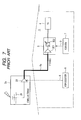
- FIG. 7 is a schematic diagram of a receiving apparatus for receiving terrestrial broadcast signals by using an outdoor antenna.
- an antenna device 2a equipped with the amplifier 22 is installed outdoors.
- the antenna device 2a is connected to the television tuner 3 through a cable 5a and is supplied with the driving voltage from the booster power source 6.
- the installation positions of the antenna devices 2 and 2a are different in accordance with the places in which the intensity of the electric field of the broadcast wave is strong and weak.
- a power supply line 8 which supplies the driving voltage, and the like.
- the antenna devices 2 and 2a are provided to both outdoor and indoor positions.
- several cables and several power supply lines 8 are required in accordance with the number of the antennas. This causes a problem in that the number of components increases and simultaneously the configuration of the apparatus becomes complicated.
- An advantage of some aspects of the invention is to provide a broadcast wave receiving apparatus which is able to receive a desired broadcast signal with a simple apparatus configuration without greatly changing the apparatus configuration even when the intensity of the electric field of the broadcast wave is changed.
- a broadcast wave receiving apparatus includes: a first antenna for receiving a broadcast signal; an amplifier for amplifying the received broadcast signal; a tuner for receiving the input of the signal amplified by the amplifier; a housing section having the first antenna, the amplifier, and the tuner installed therein; and an outside antenna terminal capable of being equipped with a second antenna.
- the broadcast signal received by the second antenna is input to the amplifier when the outside antenna terminal is equipped with the second antenna.
- the first antenna, the amplifier, and the tuner are installed in the housing section, and the outside antenna terminal, on which the second antenna to be installed outside can be mounted, is provided. Therefore, even in the places in which the intensity of the electric field of the broadcast wave is strong and weak, it is not necessary to greatly change the apparatus configuration, and thus it is possible to receive the desired broadcast signal by using a simple apparatus configuration. Further, compared with the known receiving apparatuses, it is possible to reduce the number of the components such as the LNAs installed in the antenna and the tuner and the cable interconnecting the antenna and the tuner.
- the first antenna when the second antenna receives the broadcast signal, it is preferred that the first antenna be controlled to prevent a frequency signal unwanted by the tuner from entering the tuner.
- the first antenna is controlled to prevent the unwanted frequency signal from entering the tuner. Therefore, it is possible to reliably receive the desired broadcast signal from the second antenna in the tuner.
- the first antenna when the first antenna receives the broadcast signal, it is preferred that the first antenna be tuned to the frequency of the received signal. In addition, when the second antenna receives the broadcast signal, it is preferred that the first antenna be tuned to the unwanted signal frequency.
- the first antenna when the first antenna receives the broadcast signal, the first antenna is tuned to the frequency of the received signal. Therefore, it is possible to receive the broadcast signal in the desired frequency band.
- the second antenna when the second antenna receives the broadcast signal, the first antenna is tuned to the unwanted signal frequency of the second antenna. Therefore, it is possible to receive the broadcast signal in the desired frequency band through the second antenna.
- the unwanted signal frequency be an image frequency corresponding to the frequency of the received signal.
- the image frequency which is a disturbing frequency of the received signal is the unwanted signal frequency. Therefore, it is possible to reliably receive the desired broadcast signal.
- the first antenna have a tuned circuit including a variable capacitor and an inductor.
- the first antenna having the tuner circuit functions as a tracking filter. Therefore, it is not necessary to separately provide the tracking filter in the tuner as in the known receiving apparatus, and thus it is possible to reduce the number of the components.
- the second antenna when the first antenna receives the broadcast signal, it is preferred that the second antenna be disconnected from the amplifier.
- the broadcast wave receiving apparatus is a broadcast wave receiving apparatus having an antenna installed indoors.
- the broadcast wave receiving apparatus is used as a television signal receiving apparatus for receiving a television signal for terrestrial broadcast.
- the television signal receiving apparatus will be described as an example.
- Figs. 1 and 2 are schematic diagrams illustrating a television signal receiving apparatus (hereinafter, it is referred to as a "receiving apparatus") according to the embodiment of the invention.
- Fig. 1 shows a configuration of the receiving apparatus when the intensity of an electric field of a broadcast wave is weak.
- Fig. 2 shows a configuration of the receiving apparatus when the intensity of the electric field of the broadcast wave is strong.
- the receiving apparatus 10 includes a set-top box (STB) 11 and a power supply device 12 and a display device 13 which are connected to the STB 11, and those are installed indoors.
- STB set-top box
- the STB (housing section) 11 is formed as a single casing.
- the casing includes an indoor antenna (a first antenna) 21 which functions as an antenna installed indoors, an LNA 22 which is connected to the antenna 21, and a television tuner 24 connected to the LNA 22 through a cable 23.
- the STB 11 is provided with an input terminal 26 as an outside antenna terminal on which an outdoor antenna (a second antenna) 25 installed outdoors can be mounted.
- the signal path L1 extending from the input terminal 26, on which the outdoor antenna 25 is mounted, is connected to the midpoint P between the antenna 21 and the LNA 22.
- a power terminal 27 is installed on the STB 11, and the power supply device 12 is connected to the STB 11 through a power cable 28.
- a power source voltage is supplied from the power supply device 12 to the LNA 22 and the television tuner 24 through a power supply line L2.
- the antenna 21 is formed as a tunable antenna which is able to change a tuning frequency.
- the antenna 21 receives the television signal and outputs the signal to the LNA 22.
- the LNA 22 amplifies the television signal, which is output from the antenna 21, to a predetermined level, and outputs the amplified television signal to the television tuner 24.
- the tunable antenna is used as the indoor antenna, it is possible to improve gain, compared with other antennas such as a passive antenna having the same size. As a result, this configuration is preferable in that the size of the STB 11 is reduced.
- the antenna 21 has a tuned circuit including a variable capacitor and an inductor, and functions as a tracking filter for removing a signal out of a desired frequency band.
- the tracking filter in the tuner is not needed unlike the known receiving apparatus, and thus it is possible to reduce the number of components.
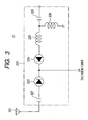
- Fig. 3 is a circuit diagram of the general tunable antenna 21.
- the tunable antenna 21 includes an antenna element 221 and a matching (tuned) circuit 222.
- the matching circuit 222 includes varactor diodes (variable capacitor) 223 and 224 and an LC serial resonance circuit of a coil (an inductor) 225.
- Anodes of the varactor diodes 223 and 224 are applied with a tuning voltage (an antenna band control signal) for controlling a resonance frequency from the television tuner 24 to be described later.
- an output terminal of the matching circuit 222 is connected in parallel to the coil 226 for matching with the television tuner 24 at the posterior end.
- both ends of the matching circuit 222 are respectively connected to the antenna element 221 and the LNA 22 through DC-cut capacitors 227 and 228.
- the television tuner 24 mainly includes a mixer 31, a local oscillator 32, and a demodulating section 33.
- the mixer 31 mixes a local oscillating signal generated by the local oscillator 32 with the amplified signal output from the LNA 22, converts the signal into a baseband frequency signal, and outputs the signal to the demodulating section 33.
- the demodulating section 33 demodulates the baseband frequency signal, which is output from the mixer 31, and outputs the modulated video audio signal to a display device 13.
- the television tuner 24 is able to control the tuning frequency of the antenna 21 by sending an antenna band control signal S to the indoor antenna 21.
- the television tuner 24 operates to prevent the unwanted frequency signal in the television tuner 24 from entering the television tuner 24 by making the indoor antenna 21 function as a tracking filter.
- the antenna 21 is tuned to the frequency of the received signal.
- the antenna band control signal S is transmitted so that the antenna 21 is tuned to an image frequency corresponding to the frequency of the received signal.
- the outdoor antenna In a place in which the intensity of the electric field of the broadcast wave is weak, the outdoor antenna is used in order to improve the level of signal reception quality. Therefore, as shown in Fig. 1 , the antenna 25 is connected to the input terminal 26.
- the television signal received by the antenna 25 is output to the LNA 22 through the signal path L1, amplified to a predetermined level by the LNA 22, and then output to the television tuner 24.
- the antenna band control signals for setting the tuning frequency to the image frequency is input from the television tuner 24 to the indoor antenna 21, the frequency of the antenna 21 is controlled so that the impedance of the antenna 21 is lowered.
- the image frequency signal which is included in the received signal of the antenna 25, is output to the antenna 21 through the signal path L1, and only the desired signal is output to the LNA 22.
- the outdoor antenna 25 is disconnected from the LNA 22.
- the television signal received by the indoor antenna 21 is output to the LNA 22, amplified to a predetermined level, and output to the television tuner 24.
- the outdoor antenna 25 may be separated from the input terminal 26, and a switch portion for switching the connection state and the non connection state of the antenna 25 may be provided at the midpoint P.
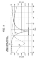
- Figs. 4 and 5 are characteristic graphs illustrating signal pass characteristics in the television tuner 24 when the outdoor antenna 25 receives the signal.
- Fig. 4 shows the pass characteristics when the reception channel frequency is 473 MHz.
- Fig. 5 shows the pass characteristics when the reception channel frequency is 580 MHz.
- the solid lines (W1, W3) represent the pass characteristics of the television tuner 24, and the dashed lines (W2, W4) represent reflection characteristics as viewed from the television tuner 24.
- loss is minimized at the reception channel frequency of 473 MHz, and a trap is formed at the image frequency, thereby removing the image frequency.
- the solid line W3 shown in Fig. 5 loss is minimized at the reception channel frequency of 580 MHz, and a trap is formed at the image frequency, thereby removing the image frequency.
- the indoor antenna 21, the LNA 22, and the television tuner 24 are installed in the STB (the housing section) 11, and the input terminal 26, on which the outdoor antenna 25 to be installed outside can be mounted, is also installed thereon. Therefore, even in the places in which the intensity of the electric field of the broadcast wave is strong and weak, it is not necessary to greatly change the apparatus configuration, and thus it is possible to receive the desired broadcast signal by using a simple apparatus configuration.
- the antenna 21 functions as a tracking filter by being tuned to the image frequency of the frequency received by the antenna 21.
- the embodiments of the invention can be applied to the broadcast wave receiving apparatuses for receiving the broadcast signal such as a television broadcast signal.
Landscapes
- Input Circuits Of Receivers And Coupling Of Receivers And Audio Equipment (AREA)
Abstract
A broadcast wave receiving apparatus (10) includes: a first antenna (21) for receiving a broadcast signal; an amplifier (22) for amplifying the received broadcast signal; a tuner (24) for receiving input of the signal amplified by the amplifier (22); a housing section (11) having the first antenna (21), the amplifier (22), and the tuner (24) installed therein; and an outside antenna terminal (26) capable of being equipped with a second antenna (25). The broadcast signal received by the second antenna (25) is input to the amplifier (22) when the outside antenna terminal (26) is equipped with the second antenna (25).
Description
- The present application contains subject matter related to Japanese Patent Application No.
2008-221776 - The present invention relates to a broadcast wave receiving apparatus for receiving broadcast signals such as television broadcast signals.
- Generally, in a place where the intensity of an electric field of a broadcast wave is strong, most of the receiving apparatuses receive terrestrial broadcast signals by using indoor antennas which can be easily installed.
Fig. 6 is a schematic diagram of a receiving apparatus for receiving terrestrial broadcast signals by using an indoor antenna. A receivingapparatus 1 includes anantenna device 2 which is installed indoors and is equipped with an amplifier (LNA: Low Noise Amplifier) 22, a television tuner (STB) 3 which is connected to theantenna device 2 through acable 5 and has an LNA 301 and atracking filter 302, and adisplay device 4 which is connected to thetelevision tuner 3. Theantenna device 2 and thetelevision tuner 3 are respectively supplied with driving voltages from abooster power source 6 and a tuner power source 7. Some of the receiving apparatuses have a further simple configuration in which the antenna device and the television tuner are housed in a metal casing (Japanese Unexamined Patent Application Publication No.2006-345238 - On the other hand, in a place where the intensity of the electric field of the broadcast wave is weak, most of the receiving apparatuses receive the terrestrial broadcast signals by installing outdoor antennas instead of indoor antennas.
Fig. 7 is a schematic diagram of a receiving apparatus for receiving terrestrial broadcast signals by using an outdoor antenna. In thereceiving apparatus 1, anantenna device 2a equipped with theamplifier 22 is installed outdoors. Theantenna device 2a is connected to thetelevision tuner 3 through acable 5a and is supplied with the driving voltage from thebooster power source 6. - However, in the known receiving apparatuses, the installation positions of the
antenna devices antenna devices power supply line 8 which supplies the driving voltage, and the like. In this case, it can be considered that theantenna devices power supply lines 8 are required in accordance with the number of the antennas. This causes a problem in that the number of components increases and simultaneously the configuration of the apparatus becomes complicated. - An advantage of some aspects of the invention is to provide a broadcast wave receiving apparatus which is able to receive a desired broadcast signal with a simple apparatus configuration without greatly changing the apparatus configuration even when the intensity of the electric field of the broadcast wave is changed.
- According to an aspect of the invention, a broadcast wave receiving apparatus includes: a first antenna for receiving a broadcast signal; an amplifier for amplifying the received broadcast signal; a tuner for receiving the input of the signal amplified by the amplifier; a housing section having the first antenna, the amplifier, and the tuner installed therein; and an outside antenna terminal capable of being equipped with a second antenna. The broadcast signal received by the second antenna is input to the amplifier when the outside antenna terminal is equipped with the second antenna.
- With such a configuration, the first antenna, the amplifier, and the tuner are installed in the housing section, and the outside antenna terminal, on which the second antenna to be installed outside can be mounted, is provided. Therefore, even in the places in which the intensity of the electric field of the broadcast wave is strong and weak, it is not necessary to greatly change the apparatus configuration, and thus it is possible to receive the desired broadcast signal by using a simple apparatus configuration. Further, compared with the known receiving apparatuses, it is possible to reduce the number of the components such as the LNAs installed in the antenna and the tuner and the cable interconnecting the antenna and the tuner.
- Further, in this aspect of the invention, when the second antenna receives the broadcast signal, it is preferred that the first antenna be controlled to prevent a frequency signal unwanted by the tuner from entering the tuner.
- With such a configuration, when the second antenna receives the broadcast signal, the first antenna is controlled to prevent the unwanted frequency signal from entering the tuner. Therefore, it is possible to reliably receive the desired broadcast signal from the second antenna in the tuner.
- Further, in this aspect of the invention, when the first antenna receives the broadcast signal, it is preferred that the first antenna be tuned to the frequency of the received signal. In addition, when the second antenna receives the broadcast signal, it is preferred that the first antenna be tuned to the unwanted signal frequency.
- With such a configuration, when the first antenna receives the broadcast signal, the first antenna is tuned to the frequency of the received signal. Therefore, it is possible to receive the broadcast signal in the desired frequency band. On the other hand, when the second antenna receives the broadcast signal, the first antenna is tuned to the unwanted signal frequency of the second antenna. Therefore, it is possible to receive the broadcast signal in the desired frequency band through the second antenna.
- Further, in this aspect of the invention, it is preferred that the unwanted signal frequency be an image frequency corresponding to the frequency of the received signal. In this case, the image frequency which is a disturbing frequency of the received signal is the unwanted signal frequency. Therefore, it is possible to reliably receive the desired broadcast signal.
- Further, in this aspect of the invention, it is preferred that the first antenna have a tuned circuit including a variable capacitor and an inductor. In this case, the first antenna having the tuner circuit functions as a tracking filter. Therefore, it is not necessary to separately provide the tracking filter in the tuner as in the known receiving apparatus, and thus it is possible to reduce the number of the components.
- Further, in this aspect of the invention, when the first antenna receives the broadcast signal, it is preferred that the second antenna be disconnected from the amplifier.
- With such a configuration, when the intensity of the electric field of the broadcast wave is strong, it is possible to receive the broadcast signal with the first antenna by disconnecting the second antenna from the amplifier. In contrast, when the intensity of the electric field is weak, it is possible to receive the broadcast signal with the second antenna by connecting the second antenna with the amplifier.
- According to the aspects of the invention, it is possible to receive the desired broadcast signal with a simple apparatus configuration without greatly changing the apparatus configuration even when the intensity of the electric field of the broadcast wave is changed.
-
-
Fig. 1 is a schematic diagram illustrating a television signal receiving apparatus according to an embodiment of the invention. -
Fig. 2 is a schematic diagram illustrating the television signal receiving apparatus according to the embodiment of the invention. -
Fig. 3 is a circuit configuration diagram of a general tunable antenna. -
Fig. 4 is a characteristic graph illustrating signal pass characteristics in a television tuner. -
Fig. 5 is a characteristic graph illustrating signal pass characteristics in the television tuner. -
Fig. 6 is a schematic diagram illustrating a known television signal receiving apparatus. -
Fig. 7 is a schematic diagram illustrating the known television signal receiving apparatus. - Hereinafter, an embodiment of the present invention will be described in detail with reference to the accompanying drawings. The broadcast wave receiving apparatus according to the embodiment is a broadcast wave receiving apparatus having an antenna installed indoors. For example, the broadcast wave receiving apparatus is used as a television signal receiving apparatus for receiving a television signal for terrestrial broadcast. Hereinafter, the television signal receiving apparatus will be described as an example.
-
Figs. 1 and2 are schematic diagrams illustrating a television signal receiving apparatus (hereinafter, it is referred to as a "receiving apparatus") according to the embodiment of the invention.Fig. 1 shows a configuration of the receiving apparatus when the intensity of an electric field of a broadcast wave is weak.Fig. 2 shows a configuration of the receiving apparatus when the intensity of the electric field of the broadcast wave is strong. As shown inFigs. 1 and2 , thereceiving apparatus 10 includes a set-top box (STB) 11 and apower supply device 12 and adisplay device 13 which are connected to theSTB 11, and those are installed indoors. - The STB (housing section) 11 is formed as a single casing. The casing includes an indoor antenna (a first antenna) 21 which functions as an antenna installed indoors, an
LNA 22 which is connected to theantenna 21, and atelevision tuner 24 connected to theLNA 22 through acable 23. In addition, theSTB 11 is provided with aninput terminal 26 as an outside antenna terminal on which an outdoor antenna (a second antenna) 25 installed outdoors can be mounted. The signal path L1 extending from theinput terminal 26, on which theoutdoor antenna 25 is mounted, is connected to the midpoint P between theantenna 21 and theLNA 22. Moreover, apower terminal 27 is installed on theSTB 11, and thepower supply device 12 is connected to theSTB 11 through apower cable 28. A power source voltage is supplied from thepower supply device 12 to theLNA 22 and thetelevision tuner 24 through a power supply line L2. - The
antenna 21 is formed as a tunable antenna which is able to change a tuning frequency. Theantenna 21 receives the television signal and outputs the signal to theLNA 22. TheLNA 22 amplifies the television signal, which is output from theantenna 21, to a predetermined level, and outputs the amplified television signal to thetelevision tuner 24. Here, when the tunable antenna is used as the indoor antenna, it is possible to improve gain, compared with other antennas such as a passive antenna having the same size. As a result, this configuration is preferable in that the size of theSTB 11 is reduced. - In addition, the
antenna 21 has a tuned circuit including a variable capacitor and an inductor, and functions as a tracking filter for removing a signal out of a desired frequency band. Thereby, the tracking filter in the tuner is not needed unlike the known receiving apparatus, and thus it is possible to reduce the number of components. -
Fig. 3 is a circuit diagram of the generaltunable antenna 21. As shown in the drawing, thetunable antenna 21 includes anantenna element 221 and a matching (tuned)circuit 222. Thematching circuit 222 includes varactor diodes (variable capacitor) 223 and 224 and an LC serial resonance circuit of a coil (an inductor) 225. Anodes of thevaractor diodes television tuner 24 to be described later. Further, an output terminal of thematching circuit 222 is connected in parallel to thecoil 226 for matching with thetelevision tuner 24 at the posterior end. Furthermore, both ends of thematching circuit 222 are respectively connected to theantenna element 221 and theLNA 22 through DC-cut capacitors - The
television tuner 24 mainly includes amixer 31, alocal oscillator 32, and ademodulating section 33. Themixer 31 mixes a local oscillating signal generated by thelocal oscillator 32 with the amplified signal output from theLNA 22, converts the signal into a baseband frequency signal, and outputs the signal to thedemodulating section 33. Thedemodulating section 33 demodulates the baseband frequency signal, which is output from themixer 31, and outputs the modulated video audio signal to adisplay device 13. - Further, the
television tuner 24 is able to control the tuning frequency of theantenna 21 by sending an antenna band control signal S to theindoor antenna 21. In particular, when theoutdoor antenna 25 receives the broadcast signal, thetelevision tuner 24 operates to prevent the unwanted frequency signal in thetelevision tuner 24 from entering thetelevision tuner 24 by making theindoor antenna 21 function as a tracking filter. For example, when theindoor antenna 21 is used, theantenna 21 is tuned to the frequency of the received signal. On the other hand, when theoutdoor antenna 25 is used, the antenna band control signal S is transmitted so that theantenna 21 is tuned to an image frequency corresponding to the frequency of the received signal. With such a configuration, when theoutdoor antenna 25 receives the broadcast signal, theantenna 21 is tuned to the image frequency. Therefore, the image frequency signal as a disturbing signal flows in theantenna 21 and is attenuated, thereby being prevented from entering thetelevision tuner 24. - Next, an operation of the
signal receiving apparatus 10 according to the embodiment will be described. - In a place in which the intensity of the electric field of the broadcast wave is weak, the outdoor antenna is used in order to improve the level of signal reception quality. Therefore, as shown in
Fig. 1 , theantenna 25 is connected to theinput terminal 26. The television signal received by theantenna 25 is output to theLNA 22 through the signal path L1, amplified to a predetermined level by theLNA 22, and then output to thetelevision tuner 24. At this time, since the antenna band control signals for setting the tuning frequency to the image frequency is input from thetelevision tuner 24 to theindoor antenna 21, the frequency of theantenna 21 is controlled so that the impedance of theantenna 21 is lowered. Accordingly, the image frequency signal, which is included in the received signal of theantenna 25, is output to theantenna 21 through the signal path L1, and only the desired signal is output to theLNA 22. In contrast, in a place in which the intensity of the electric field of the broadcast wave is strong, it is possible to maintain the level of the signal reception quality. Therefore, as shown inFig. 2 , theoutdoor antenna 25 is disconnected from theLNA 22. Then, the television signal received by theindoor antenna 21 is output to theLNA 22, amplified to a predetermined level, and output to thetelevision tuner 24. Here, in order to disconnect theoutdoor antenna 25 from theLNA 22, theoutdoor antenna 25 may be separated from theinput terminal 26, and a switch portion for switching the connection state and the non connection state of theantenna 25 may be provided at the midpoint P. -
Figs. 4 and5 are characteristic graphs illustrating signal pass characteristics in thetelevision tuner 24 when theoutdoor antenna 25 receives the signal.Fig. 4 shows the pass characteristics when the reception channel frequency is 473 MHz.Fig. 5 shows the pass characteristics when the reception channel frequency is 580 MHz. In both drawings, the solid lines (W1, W3) represent the pass characteristics of thetelevision tuner 24, and the dashed lines (W2, W4) represent reflection characteristics as viewed from thetelevision tuner 24. As can be seen from the solid line W1 inFig. 4 , loss is minimized at the reception channel frequency of 473 MHz, and a trap is formed at the image frequency, thereby removing the image frequency. Likewise, in the solid line W3 shown inFig. 5 , loss is minimized at the reception channel frequency of 580 MHz, and a trap is formed at the image frequency, thereby removing the image frequency. - As described above, according to the embodiment, the
indoor antenna 21, theLNA 22, and thetelevision tuner 24 are installed in the STB (the housing section) 11, and theinput terminal 26, on which theoutdoor antenna 25 to be installed outside can be mounted, is also installed thereon. Therefore, even in the places in which the intensity of the electric field of the broadcast wave is strong and weak, it is not necessary to greatly change the apparatus configuration, and thus it is possible to receive the desired broadcast signal by using a simple apparatus configuration. In particular, when the intensity of the electric field of the broadcast wave is weak, the broadcast signal can be received by theoutdoor antenna 25. In this case, theantenna 21 functions as a tracking filter by being tuned to the image frequency of the frequency received by theantenna 21. Therefore, it is possible to reliably receive only the desired broadcast signal by cutting the input of the image frequency signal to thetelevision tuner 24. Further, compared with the known receiving apparatuses, it is possible to reduce the number of components such as the LNAs 22 installed in theantennas television tuner 24 and thecable 23 interconnecting theantennas television tuner 24. - Further, the invention is not limited to the embodiment, and may be modified in various forms. In the embodiment, dimensions and shapes shown in the accompanying drawings are not limited to this embodiment, and may be appropriately modified in the range in which the advantage of the invention is exhibited. In addition, various modifications and variations may be made without departing from the technical scope of the invention.
- The embodiments of the invention can be applied to the broadcast wave receiving apparatuses for receiving the broadcast signal such as a television broadcast signal.
- It should be understood by those skilled in the art that various modifications, combinations, sub-combinations and alterations may occur depending on design requirements and other factors insofar as they are within the scope of the appended claims of the equivalents thereof.
Claims (6)
- A broadcast wave receiving apparatus (10) comprising:a first antenna (21) for receiving a broadcast signal;an amplifier (22) for amplifying the received broadcast signal;a tuner (24) for receiving input of the signal amplified by the amplifier (22);a housing section (11) having the first antenna (21), the amplifier (22), and the tuner (24) installed therein; andan outside antenna terminal (26) capable of being equipped with a second antenna (25) to be installed outside,wherein the broadcast signal received by the second antenna (25) is input to the amplifier (22) when the outside antenna terminal (26) is equipped with the second antenna (25).
- The broadcast wave receiving apparatus (10) according to claim 1, wherein when the second antenna (25) receives the broadcast signal, the first antenna (21) is controlled to prevent a frequency signal unwanted in the tuner (24) from entering the tuner (24).
- The broadcast wave receiving apparatus (10) according to claim 2,
wherein when the first antenna (21) receives the broadcast signal, the first antenna (21) is tuned to a frequency of the received signal, and
wherein when the second antenna (25) receives the broadcast signal, the first antenna (21) is tuned to the unwanted signal frequency. - The broadcast wave receiving apparatus (10) according to claim 2 or 3, wherein the unwanted signal frequency is an image frequency corresponding to a frequency of the received signal.
- The broadcast wave receiving apparatus (10) according to any one of claims 1 to 4, wherein the first antenna (21) has a tuned circuit including a variable capacitor and an inductor.
- The broadcast wave receiving apparatus (10) according to any one of claims 1 to 5, wherein when the first antenna (21) receives the broadcast signal, the second antenna (25) is disconnected from the amplifier (22).
Applications Claiming Priority (1)
| Application Number | Priority Date | Filing Date | Title |
|---|---|---|---|
| JP2008221776A JP2010057065A (en) | 2008-08-29 | 2008-08-29 | Broadcast wave receiving apparatus |
Publications (1)
| Publication Number | Publication Date |
|---|---|
| EP2159873A1 true EP2159873A1 (en) | 2010-03-03 |
Family
ID=41350649
Family Applications (1)
| Application Number | Title | Priority Date | Filing Date |
|---|---|---|---|
| EP09010348A Withdrawn EP2159873A1 (en) | 2008-08-29 | 2009-08-11 | Broadcast wave receiving apparatus |
Country Status (2)
| Country | Link |
|---|---|
| EP (1) | EP2159873A1 (en) |
| JP (1) | JP2010057065A (en) |
Citations (4)
| Publication number | Priority date | Publication date | Assignee | Title |
|---|---|---|---|---|
| US4835608A (en) * | 1988-05-31 | 1989-05-30 | Zenith Electronics Corporation | Image trap filter circuit |
| US5201072A (en) * | 1990-04-05 | 1993-04-06 | Pioneer Electronic Corporation | Tuner for diversity reception having a fixed antenna and a retractive antenna |
| JP2006345238A (en) | 2005-06-09 | 2006-12-21 | Matsushita Electric Ind Co Ltd | Terrestrial broadcast receiver |
| JP2008221776A (en) | 2007-03-15 | 2008-09-25 | Asahi Kasei Chemicals Corp | Laminated film |
Family Cites Families (2)
| Publication number | Priority date | Publication date | Assignee | Title |
|---|---|---|---|---|
| JPH0746497A (en) * | 1993-07-23 | 1995-02-14 | Sony Corp | Receiver |
| JP2001057529A (en) * | 1999-08-18 | 2001-02-27 | Mitsubishi Electric Corp | Wireless device |
-
2008
- 2008-08-29 JP JP2008221776A patent/JP2010057065A/en not_active Withdrawn
-
2009
- 2009-08-11 EP EP09010348A patent/EP2159873A1/en not_active Withdrawn
Patent Citations (4)
| Publication number | Priority date | Publication date | Assignee | Title |
|---|---|---|---|---|
| US4835608A (en) * | 1988-05-31 | 1989-05-30 | Zenith Electronics Corporation | Image trap filter circuit |
| US5201072A (en) * | 1990-04-05 | 1993-04-06 | Pioneer Electronic Corporation | Tuner for diversity reception having a fixed antenna and a retractive antenna |
| JP2006345238A (en) | 2005-06-09 | 2006-12-21 | Matsushita Electric Ind Co Ltd | Terrestrial broadcast receiver |
| JP2008221776A (en) | 2007-03-15 | 2008-09-25 | Asahi Kasei Chemicals Corp | Laminated film |
Also Published As
| Publication number | Publication date |
|---|---|
| JP2010057065A (en) | 2010-03-11 |
Similar Documents
| Publication | Publication Date | Title |
|---|---|---|
| EP0149533B2 (en) | Apparatus for receiving super high frequency signals | |
| US7817094B2 (en) | Antenna, and wireless module, wireless unit and wireless apparatus having the antenna | |
| US20120120322A1 (en) | Portable wireless device | |
| CN102668557B (en) | A device that protects satellite reception from strong terrestrial signals | |
| US20110169712A1 (en) | Portable radio equipment | |
| JP3490023B2 (en) | TV signal receiving tuner | |
| CN100426665C (en) | Automatic gain control for a tuner | |
| US20070238436A1 (en) | Radio reception apparatus receiving multiple radio signals different in frequency | |
| EP1739857A2 (en) | Antenna switching system | |
| JP2010130328A (en) | Television broadcast receiving circuit | |
| EP1124329A2 (en) | Television tuner input circuit | |
| EP3163776A1 (en) | A low noise block downconverter circuit | |
| KR20070020079A (en) | TV-RF input circuit and tuner including the same | |
| KR101401835B1 (en) | Frequency limiting amplifier in a fsk receiver | |
| EP1533863A1 (en) | An Active Antenna | |
| JP2010057065A (en) | Broadcast wave receiving apparatus | |
| US20070222524A1 (en) | Antenna Amplfier | |
| EP1198066A2 (en) | Avoidance of interfernce between items of electrial apparatus | |
| KR101084906B1 (en) | Terrestrial and satellite tuner with loop-through circuit | |
| US20110051015A1 (en) | Television signal receiving tuner | |
| EP2139112A1 (en) | Double-tuned circuit | |
| JP2011239004A (en) | High-frequency signal receiver | |
| US20050162568A1 (en) | Television tuner capable of improving image disturbance when receiving UHF band | |
| KR20060010346A (en) | Input circuit of tuner for airwave broadcasting receiver | |
| WO2018106402A1 (en) | System and apparatus for surge energy protection |
Legal Events
| Date | Code | Title | Description |
|---|---|---|---|
| PUAI | Public reference made under article 153(3) epc to a published international application that has entered the european phase |
Free format text: ORIGINAL CODE: 0009012 |
|
| AK | Designated contracting states |
Kind code of ref document: A1 Designated state(s): AT BE BG CH CY CZ DE DK EE ES FI FR GB GR HR HU IE IS IT LI LT LU LV MC MK MT NL NO PL PT RO SE SI SK SM TR |
|
| AX | Request for extension of the european patent |
Extension state: AL BA RS |
|
| STAA | Information on the status of an ep patent application or granted ep patent |
Free format text: STATUS: THE APPLICATION HAS BEEN WITHDRAWN |
|
| 18W | Application withdrawn |
Effective date: 20100712 |