EP2159807A1 - A capacitor and a method thereof - Google Patents
A capacitor and a method thereof Download PDFInfo
- Publication number
- EP2159807A1 EP2159807A1 EP08290812A EP08290812A EP2159807A1 EP 2159807 A1 EP2159807 A1 EP 2159807A1 EP 08290812 A EP08290812 A EP 08290812A EP 08290812 A EP08290812 A EP 08290812A EP 2159807 A1 EP2159807 A1 EP 2159807A1
- Authority
- EP
- European Patent Office
- Prior art keywords
- tubular conductor
- inner tubular
- capacitor
- ring
- slot
- Prior art date
- Legal status (The legal status is an assumption and is not a legal conclusion. Google has not performed a legal analysis and makes no representation as to the accuracy of the status listed.)
- Withdrawn
Links
Images



Classifications
-
- H—ELECTRICITY
- H01—ELECTRIC ELEMENTS
- H01G—CAPACITORS; CAPACITORS, RECTIFIERS, DETECTORS, SWITCHING DEVICES, LIGHT-SENSITIVE OR TEMPERATURE-SENSITIVE DEVICES OF THE ELECTROLYTIC TYPE
- H01G4/00—Fixed capacitors; Processes of their manufacture
- H01G4/28—Tubular capacitors
-
- H—ELECTRICITY
- H01—ELECTRIC ELEMENTS
- H01G—CAPACITORS; CAPACITORS, RECTIFIERS, DETECTORS, SWITCHING DEVICES, LIGHT-SENSITIVE OR TEMPERATURE-SENSITIVE DEVICES OF THE ELECTROLYTIC TYPE
- H01G5/00—Capacitors in which the capacitance is varied by mechanical means, e.g. by turning a shaft; Processes of their manufacture
- H01G5/16—Capacitors in which the capacitance is varied by mechanical means, e.g. by turning a shaft; Processes of their manufacture using variation of distance between electrodes
Definitions
- the invention relates to a tubular capacitor and to a method of producing a tubular capacitor.
- a capacitor is an electrical device that stores energy in the electrical field between a pair of conductors or plates.
- a capacitor consists of two of these plates or conductive electrodes separated by a dielectric, that prevents charge from moving directly between the plates.
- a simple capacitor consists of two wide, flat and parallel plates separated by a thin dielectric layer.
- a property called the capacitance measures the charge stored on each plate for a given voltage. In general, capacitance is greater in devices with large plate areas, separated by small distances. When a dielectric is present between two charge plates, its molecules become polarized and reduce the internal electrical field and therefore the voltage.
- the invention relates to a capacitor comprising: an outer tubular conductor having a first and a second end portion; a ring slot in the outer tubular conductor extending to the first end portion and having a ring diameter; an inner tubular conductor having a third and forth end portion; a tubular slot in the inner tubular conductor extending to the forth end portion, the tubular slot having an approximate diameter of the ring diameter.
- the inner tubular conductor is partially inside the ring slot of the outer tubular conductor and have a separation distance between the forth portion of the inner tubular conductor and a bottom of the ring slot.
- the outer tubular conductor and the inner tubular conductor form a capacitance and correspond to the conductive electrodes or plates of the capacitor.
- One of the advantage of the embodiments is that the structural design of the conductive electrodes of the capacitor allow reaching electrical field lines and capacitance levels with a fraction of the size of traditional conductors or plates, as electrical field is formed on at least two different sections of the capacitor.
- the electrical field is formed between the outer tubular conductor and the inner tubular conductor and from an internal section of the outer tubular conductor and the inner tubular conductor.
- the embodiments also reduces the size and the length of the conductors, as well as the weight of the capacitor. Further, as the conductors are shorter, the losses are also reduced.
- the capacitor further comprises: a second ring slot in the outer tubular conductor extending to the first end portion and having a second ring diameter, wherein the second ring diameter is smaller than the first ring diameter; and an second inner tubular conductor in the first tubular slot having an approximate inner ring diameter of the second ring slot; wherein the second inner tubular conductor is partially inside the second ring slot; wherein the second inner tubular conductor is coupled to the inner tubular conductor.
- the capacitor is adapted for filtering out direct current, low frequencies and allowing transmission of alternating currents at high frequencies.
- the separation distance between the inner tubular conductor and the ring slot is adjusted for modifying the capacitance.
- the second inner tubular conductor and the inner tubular conductor form a single conductor.
- the ring slot is filled with a dielectric, or a non-conductive material, or air.
- the separation distance between the inner tubular conductor and the ring slot reaches a predetermined value for obtaining electric field lines between the outer tubular conductor and the inner tubular conductor.
- the invention in another aspect, relates to a method of producing a capacitor comprising the steps of: providing an outer tubular conductor having a first and a second end portion; forming a ring slot in the outer tubular conductor extending to the first end portion and having a ring diameter; providing an inner tubular conductor having a third and forth end portion; forming a tubular slot in the inner tubular conductor extending to the forth end portion, the tubular slot having an approximate diameter of the ring diameter; and placing the inner tubular conductor inside the ring slot of the outer tubular conductor with a separation distance between the forth portion of the inner tubular conductor and a bottom of the ring slot.
- the method of producing a capacitor further comprises: forming a second ring slot in the outer tubular conductor extending to the first end portion and having a second ring diameter, wherein the second ring diameter is smaller than the first ring diameter; forming an second inner tubular conductor in the first tubular slot having an approximate inner ring diameter of the second ring slot; and placing the second inner tubular conductor inside the second ring slot; wherein the second inner tubular conductor is coupled to the inner tubular conductor.
- the separation distance between the inner tubular conductor and the ring slot is adjusted for modifying the capacitance.
- the second inner tubular conductor and the inner tubular conductor form a single conductor.
- the separation distance between the inner tubular conductor and the ring slot reaches a predetermined value for obtaining a direction of electric field lines between the outer tubular conductor and the inner tubular conductor.
- Fig. 1 shows a 3-D view of the capacitor 100 that comprises an outer tubular conductor 101 having a first end portion 102 and a second end portion 103.
- the capacitor 100 further comprises an inner tubular conductor 104 having a third end portion 105 and a fourth end portion not represented in the figure 1 .
- the outer tubular conductor 101 further comprises a ring slot that extends to the first end portion 102 of the outer tubular conductor and that has a ring diameter.
- the inner tubular conductor 104 is partially inside the ring slot of the outer tubular conductor 101 and has a separation distance between the fourth portion of the inner tubular conductor 104 and a bottom of the ring slot.
- the outer tubular conductor 101 and the inner tubular conductor 104 are adapted to form a capacitance.
- the capacitor is adapted for filtering out direct current and low frequencies, and letting in the transmission of alternating currents.
- the separation distance between the inner tubular conductor and the ring slot may be adjusted for modifying the capacitance values.
- the second inner tubular conductor and the inner tubular conductor may form a single conductor.
- the ring slot 201 may be partially or completely filled with a dielectric, a non-conductive material or air. Further, the separation distance between the inner tubular conductor and the ring slot may reach a predetermined value for obtaining electrical field lines between the outer tubular conductor 101 and the inner tubular conductor 104.
- the outer tubular conductor 101 and the inner tubular conductor 104 are conductive electrodes or plates of the capacitor.
- FIG. 2 shows a longitudinal cut of the capacitor 200.
- An outer tubular conductor 101 includes a first end portion 102 and a second end portion 103.
- a ring slot 201 in the outer tubular conductor 101 extends to the first end portion 102 and has a ring diameter 202.
- An inner tubular conductor 104 has a third end portion 105 and a sixth end portion 203.
- a tubular slot 204 in the inner tubular conductor 104 extends to the fourth end portion 203 and has an approximate diameter of the ring diameter 202.
- the inner tubular conductor 104 is partially inside the ring slot 201 of the outer tubular conductor 101.
- the inner tubular conductor and the outer tubular conductor has a separation distance 205 between the fourth end portion 203 and a bottom 206 of the ring slot 201.
- the outer tubular conductor 101 and the inner tubular conductor 104 are adapted to form a capacitance.
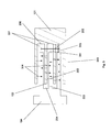
- Fig. 3 shows a longitudinal cut of an embodiment of the capacitor 300.
- the capacitor 300 comprises an outer tubular conductor 101.
- the outer tubular conductor 101 comprises a ring slot 201 having a ring diameter 202.
- An inner tubular conductor 104 includes a tubular slot 204.
- the tubular slot has an approximate diameter of the ring diameter 202.
- the capacitor 300 further comprises a second ring slot 301 in the outer tubular conductor 101 extending to the first end portion 102 and comprising a second ring diameter 302.
- the second ring diameter 302 is smaller than the first ring diameter 202.
- a second inner tubular conductor 303 is in the tubular slot 204 and has an approximate inner ring diameter of the second ring diameter 302.
- the second inner tubular conductor 303 is partially inside the second ring slot 301.
- the second inner tubular conductor 303 is coupled to the inner tubular conductor 104.
- the capacitor 300 shows examples of the different field lines 304 created between the different plates formed between the outer tubular conductors and the second inner tubular conductors.
- the capacitor 300 comprises four different sections where the field lines can be formed between the outer tubular conductor and the first and second inner tubular conductors.
- the total amount of field lines, and therefore the capacitance values can be modified by changing the separation distance 205 between the fourth end portion 203 and a bottom 206 of the ring slot 201.
- Fig. 4 shows a transversal cut of the capacitor 400.
- the capacitor 400 comprises an outer tubular conductor 101, a ring slot 201 in the outer tubular conductor 101 and having a ring diameter 202.
- the capacitor 400 further comprises an inner tubular conductor 104 having a tubular slot with an approximate diameter of the ring diameter 202.
- the tubular slot in the inner tubular conductor 104 allows introducing the inner tubular conductor 104 inside the ring slot 201 of the outer tubular conductor 101.
- the capacitor is adapted for filtering out direct current and low frequencies, and allowing the transmission of alternating currents.
- the separation distance between the inner tubular conductor and the ring slot may be adjusted for modifying the capacitance values.
- the second inner tubular conductor and the inner tubular conductor may form a single conductor.
- the ring slot 201 may be partially or completely filled with a dielectric, a non-conductive material or air.
- the capacitor 400 shows examples of the different field lines 304 created between the different plates formed between the outer tubular conductors and the second inner tubular conductor
- the separation distance between the inner tubular conductor and the ring slot may reach a predetermined value for obtaining electrical field lines between the outer tubular conductor 101 and the inner tubular conductor 104.
- the outer tubular conductor 101 and the inner tubular conductor 104 are conductive electrodes or plates of the capacitor.
- any of the embodiments presented allow reducing and compacting the length of the tubular conductors and maintaining the same electrical performance for a fraction of the distance of the tubular conductors, as the number of electrical field lines is doubled thanks to the capacitance created between the at least two different fields formed between the outer conductor and the inner conductor.
- the capacitor allows blocking direct current while permitting transmission of alternating currents and may also be used for radio frequency applications and general filtering uses.
- the design of the embodiments of the invention reduces the size and the length of the conductors, as well as the weight of the capacitor. As the conductors are shorter, the losses are also reduced.
- Capacitor 101 Outer tubular conductor 102 First end portion 103 Second end portion 104 Inner tubular conductor 105 Third end portion 200 Capacitor 201 Ring slot 202 Ring diameter 203 Fourth end portion 204 Tubular slot 205 Separation distance 206 Bottom of the ring slot 300 Capacitor 301 Second ring slot 302 Second ring diameter 303 Second inner tubular conductor 304 Electrical field lines 400 Transversal cut of the conductor
Landscapes
- Engineering & Computer Science (AREA)
- Power Engineering (AREA)
- Microelectronics & Electronic Packaging (AREA)
- Manufacturing & Machinery (AREA)
- Fixed Capacitors And Capacitor Manufacturing Machines (AREA)
- Ceramic Capacitors (AREA)
Abstract
Description
- The invention relates to a tubular capacitor and to a method of producing a tubular capacitor.
- A capacitor is an electrical device that stores energy in the electrical field between a pair of conductors or plates. A capacitor consists of two of these plates or conductive electrodes separated by a dielectric, that prevents charge from moving directly between the plates. A simple capacitor consists of two wide, flat and parallel plates separated by a thin dielectric layer. A property called the capacitance measures the charge stored on each plate for a given voltage. In general, capacitance is greater in devices with large plate areas, separated by small distances. When a dielectric is present between two charge plates, its molecules become polarized and reduce the internal electrical field and therefore the voltage.
- The invention relates to a capacitor comprising: an outer tubular conductor having a first and a second end portion; a ring slot in the outer tubular conductor extending to the first end portion and having a ring diameter; an inner tubular conductor having a third and forth end portion; a tubular slot in the inner tubular conductor extending to the forth end portion, the tubular slot having an approximate diameter of the ring diameter. The inner tubular conductor is partially inside the ring slot of the outer tubular conductor and have a separation distance between the forth portion of the inner tubular conductor and a bottom of the ring slot. The outer tubular conductor and the inner tubular conductor form a capacitance and correspond to the conductive electrodes or plates of the capacitor.
- One of the advantage of the embodiments is that the structural design of the conductive electrodes of the capacitor allow reaching electrical field lines and capacitance levels with a fraction of the size of traditional conductors or plates, as electrical field is formed on at least two different sections of the capacitor. The electrical field is formed between the outer tubular conductor and the inner tubular conductor and from an internal section of the outer tubular conductor and the inner tubular conductor. The embodiments also reduces the size and the length of the conductors, as well as the weight of the capacitor. Further, as the conductors are shorter, the losses are also reduced.
- In an embodiment of the invention, the capacitor further comprises: a second ring slot in the outer tubular conductor extending to the first end portion and having a second ring diameter, wherein the second ring diameter is smaller than the first ring diameter; and an second inner tubular conductor in the first tubular slot having an approximate inner ring diameter of the second ring slot; wherein the second inner tubular conductor is partially inside the second ring slot; wherein the second inner tubular conductor is coupled to the inner tubular conductor.
- In further embodiments, the capacitor is adapted for filtering out direct current, low frequencies and allowing transmission of alternating currents at high frequencies.
- In further embodiments, the separation distance between the inner tubular conductor and the ring slot is adjusted for modifying the capacitance.
- In further embodiments, the second inner tubular conductor and the inner tubular conductor form a single conductor.
- In further embodiments, the ring slot is filled with a dielectric, or a non-conductive material, or air.
- In further embodiments, the separation distance between the inner tubular conductor and the ring slot reaches a predetermined value for obtaining electric field lines between the outer tubular conductor and the inner tubular conductor.
- In another aspect, the invention relates to a method of producing a capacitor comprising the steps of: providing an outer tubular conductor having a first and a second end portion; forming a ring slot in the outer tubular conductor extending to the first end portion and having a ring diameter; providing an inner tubular conductor having a third and forth end portion; forming a tubular slot in the inner tubular conductor extending to the forth end portion, the tubular slot having an approximate diameter of the ring diameter; and placing the inner tubular conductor inside the ring slot of the outer tubular conductor with a separation distance between the forth portion of the inner tubular conductor and a bottom of the ring slot.
- In further embodiments, the method of producing a capacitor further comprises: forming a second ring slot in the outer tubular conductor extending to the first end portion and having a second ring diameter, wherein the second ring diameter is smaller than the first ring diameter; forming an second inner tubular conductor in the first tubular slot having an approximate inner ring diameter of the second ring slot; and placing the second inner tubular conductor inside the second ring slot; wherein the second inner tubular conductor is coupled to the inner tubular conductor.
- In further embodiments, the separation distance between the inner tubular conductor and the ring slot is adjusted for modifying the capacitance. In further embodiments, the second inner tubular conductor and the inner tubular conductor form a single conductor.
- In further embodiments, the separation distance between the inner tubular conductor and the ring slot reaches a predetermined value for obtaining a direction of electric field lines between the outer tubular conductor and the inner tubular conductor.
- In the following preferred embodiments of the invention will be described in greater detail by way of example only making reference to the drawings in which:
- Figure 1
- is a schematic of an external view of the capacitor,
- Figure 2
- is a schematic of a longitudinal cut of the capacitor,
- Figure 3
- is a schematic of an embodiment of a longitudinal cut of the capacitor,
- Figure 4
- is a representation of an embodiment of a transversal cut of the capacitor.
-
Fig. 1 shows a 3-D view of thecapacitor 100 that comprises an outertubular conductor 101 having afirst end portion 102 and asecond end portion 103. Thecapacitor 100 further comprises an innertubular conductor 104 having athird end portion 105 and a fourth end portion not represented in thefigure 1 . - The outer
tubular conductor 101 further comprises a ring slot that extends to thefirst end portion 102 of the outer tubular conductor and that has a ring diameter. The innertubular conductor 104 is partially inside the ring slot of the outertubular conductor 101 and has a separation distance between the fourth portion of the innertubular conductor 104 and a bottom of the ring slot. The outertubular conductor 101 and the innertubular conductor 104 are adapted to form a capacitance. - The capacitor is adapted for filtering out direct current and low frequencies, and letting in the transmission of alternating currents. The separation distance between the inner tubular conductor and the ring slot may be adjusted for modifying the capacitance values. The second inner tubular conductor and the inner tubular conductor may form a single conductor. The
ring slot 201 may be partially or completely filled with a dielectric, a non-conductive material or air. Further, the separation distance between the inner tubular conductor and the ring slot may reach a predetermined value for obtaining electrical field lines between the outertubular conductor 101 and the innertubular conductor 104. The outertubular conductor 101 and the innertubular conductor 104 are conductive electrodes or plates of the capacitor. -
Fig. 2 shows a longitudinal cut of thecapacitor 200. An outertubular conductor 101 includes afirst end portion 102 and asecond end portion 103. Aring slot 201 in the outertubular conductor 101 extends to thefirst end portion 102 and has aring diameter 202. An innertubular conductor 104 has athird end portion 105 and asixth end portion 203. Atubular slot 204 in the innertubular conductor 104 extends to thefourth end portion 203 and has an approximate diameter of thering diameter 202. - The inner
tubular conductor 104 is partially inside thering slot 201 of the outertubular conductor 101. The inner tubular conductor and the outer tubular conductor has aseparation distance 205 between thefourth end portion 203 and abottom 206 of thering slot 201. The outertubular conductor 101 and the innertubular conductor 104 are adapted to form a capacitance. -
Fig. 3 shows a longitudinal cut of an embodiment of thecapacitor 300. Thecapacitor 300 comprises an outertubular conductor 101. The outertubular conductor 101 comprises aring slot 201 having aring diameter 202. An innertubular conductor 104 includes atubular slot 204. The tubular slot has an approximate diameter of thering diameter 202. - The
capacitor 300 further comprises asecond ring slot 301 in the outertubular conductor 101 extending to thefirst end portion 102 and comprising asecond ring diameter 302. Thesecond ring diameter 302 is smaller than thefirst ring diameter 202. A second innertubular conductor 303 is in thetubular slot 204 and has an approximate inner ring diameter of thesecond ring diameter 302. The second innertubular conductor 303 is partially inside thesecond ring slot 301. The second innertubular conductor 303 is coupled to the innertubular conductor 104. - The
capacitor 300 shows examples of thedifferent field lines 304 created between the different plates formed between the outer tubular conductors and the second inner tubular conductors. Thecapacitor 300 comprises four different sections where the field lines can be formed between the outer tubular conductor and the first and second inner tubular conductors. The total amount of field lines, and therefore the capacitance values can be modified by changing theseparation distance 205 between thefourth end portion 203 and abottom 206 of thering slot 201. -
Fig. 4 shows a transversal cut of thecapacitor 400. Thecapacitor 400 comprises an outertubular conductor 101, aring slot 201 in the outertubular conductor 101 and having aring diameter 202. Thecapacitor 400 further comprises an innertubular conductor 104 having a tubular slot with an approximate diameter of thering diameter 202. The tubular slot in the innertubular conductor 104 allows introducing the innertubular conductor 104 inside thering slot 201 of the outertubular conductor 101. - The capacitor is adapted for filtering out direct current and low frequencies, and allowing the transmission of alternating currents. The separation distance between the inner tubular conductor and the ring slot may be adjusted for modifying the capacitance values. The second inner tubular conductor and the inner tubular conductor may form a single conductor. The
ring slot 201 may be partially or completely filled with a dielectric, a non-conductive material or air. Thecapacitor 400 shows examples of thedifferent field lines 304 created between the different plates formed between the outer tubular conductors and the second inner tubular conductor - The separation distance between the inner tubular conductor and the ring slot may reach a predetermined value for obtaining electrical field lines between the outer
tubular conductor 101 and the innertubular conductor 104. The outertubular conductor 101 and the innertubular conductor 104 are conductive electrodes or plates of the capacitor. - The design of any of the embodiments presented allow reducing and compacting the length of the tubular conductors and maintaining the same electrical performance for a fraction of the distance of the tubular conductors, as the number of electrical field lines is doubled thanks to the capacitance created between the at least two different fields formed between the outer conductor and the inner conductor. The capacitor allows blocking direct current while permitting transmission of alternating currents and may also be used for radio frequency applications and general filtering uses. The design of the embodiments of the invention reduces the size and the length of the conductors, as well as the weight of the capacitor. As the conductors are shorter, the losses are also reduced.
-
100 Capacitor 101 Outer tubular conductor 102 First end portion 103 Second end portion 104 Inner tubular conductor 105 Third end portion 200 Capacitor 201 Ring slot 202 Ring diameter 203 Fourth end portion 204 Tubular slot 205 Separation distance 206 Bottom of the ring slot 300 Capacitor 301 Second ring slot 302 Second ring diameter 303 Second inner tubular conductor 304 Electrical field lines 400 Transversal cut of the conductor
Claims (13)
- A capacitor comprising:- an outer tubular conductor (101) having a first (102) and a second end portion (103);- a ring slot (201) in said outer tubular conductor (101) extending to said first end portion and having a ring diameter (202);- an inner tubular conductor (104) having a third (105) and forth end portion (203);- a tubular slot (204) in said inner tubular conductor (104) extending to said forth end portion (203), said tubular slot (204) having an approximate diameter of said ring diameter;wherein said inner tubular conductor (104) is partially inside said ring slot (201) of said outer tubular conductor (101) and has a separation distance (205) between said forth portion (203) of said inner tubular conductor (104) and a bottom (206) of said ring slot (201); wherein said outer tubular conductor (101) and said inner tubular conductor (104) form a capacitance.
- The capacitor of claim 1 further comprises:- a second ring slot (301) in said outer tubular conductor (101) extending to said first (102) end portion and having a second ring diameter (302),
wherein said second ring diameter (302) is smaller than said ring diameter (202);- an second inner tubular conductor (303) in said tubular slot (204) having an approximate inner ring diameter of said second ring slot (301);
wherein said second inner tubular conductor (303) is partially inside said second ring slot (301); wherein said second inner tubular conductor (303) is coupled to said inner tubular conductor (104). - The capacitor of claim 1 and claim 2, wherein said capacitor is adapted for filtering out direct current, low frequencies and allowing transmission of alternating currents.
- The capacitor of any of the preceding claims, wherein said separation distance between said inner tubular conductor and said ring slot is adjusted for modifying said capacitance.
- The capacitor of any of the preceding claims, wherein said second inner tubular conductor and said inner tubular conductor form a single conductor.
- The capacitor of any of the preceding claims, wherein said ring slot is filled with a dielectric, or a non-conductive material, or air.
- The capacitor of any of the preceding claims, wherein said separation distance between said inner tubular conductor and said ring slot reaches a predetermined value for obtaining electric field lines between said outer tubular conductor and said inner tubular conductor.
- The capacitor of any of the preceding claims, wherein said outer tubular conductor and said inner tubular conductor are conductive electrodes or plates of said capacitor.
- A method of producing a capacitor comprising the steps of:- providing an outer tubular conductor having a first and a second end portion;- forming a ring slot in said outer tubular conductor extending to said first end portion and having a ring diameter;- providing an inner tubular conductor having a third and forth end portion;- forming a tubular slot in said inner tubular conductor extending to said forth end portion, said tubular slot having an approximate diameter of said ring diameter;- placing said inner tubular conductor inside said ring slot of said outer tubular conductor with a separation distance between said forth portion of said inner tubular conductor and a bottom of said ring slot.
- The method of producing a capacitor of claim 9 further comprising:- forming a second ring slot in said outer tubular conductor extending to said first end portion and having a second ring diameter, wherein said second ring diameter is smaller than said first ring diameter;- forming an second inner tubular conductor in said first tubular slot having an approximate inner ring diameter of said second ring slot;- placing said second inner tubular conductor inside said second ring slot;
wherein said second inner tubular conductor is coupled to said inner tubular conductor. - The method of producing a capacitor of claim 9 or 10, wherein said separation distance between said inner tubular conductor and said ring slot is adjusted for modifying said capacitance.
- The method of producing a capacitor of any of the claims 9 to 11, wherein said second inner tubular conductor and said inner tubular conductor form a single conductor.
- The method of producing a capacitor of any of the claims 9 to 12, wherein said separation distance between said inner tubular conductor and said ring slot reaches a predetermined value for obtaining a direction of electric field lines between said outer tubular conductor and said inner tubular conductor.
Priority Applications (1)
| Application Number | Priority Date | Filing Date | Title |
|---|---|---|---|
| EP08290812A EP2159807A1 (en) | 2008-08-29 | 2008-08-29 | A capacitor and a method thereof |
Applications Claiming Priority (1)
| Application Number | Priority Date | Filing Date | Title |
|---|---|---|---|
| EP08290812A EP2159807A1 (en) | 2008-08-29 | 2008-08-29 | A capacitor and a method thereof |
Publications (1)
| Publication Number | Publication Date |
|---|---|
| EP2159807A1 true EP2159807A1 (en) | 2010-03-03 |
Family
ID=40303686
Family Applications (1)
| Application Number | Title | Priority Date | Filing Date |
|---|---|---|---|
| EP08290812A Withdrawn EP2159807A1 (en) | 2008-08-29 | 2008-08-29 | A capacitor and a method thereof |
Country Status (1)
| Country | Link |
|---|---|
| EP (1) | EP2159807A1 (en) |
Citations (5)
| Publication number | Priority date | Publication date | Assignee | Title |
|---|---|---|---|---|
| DE1026873B (en) * | 1954-04-20 | 1958-03-27 | Philips Nv | Electrical capacitor, which consists of a ceramic body forming the dielectric |
| US3618186A (en) * | 1969-09-08 | 1971-11-09 | Itt | Method of making vacuum capacitors |
| US4593341A (en) * | 1985-05-22 | 1986-06-03 | Corning Glass Works | Tubular capacitor end terminations |
| DE19809752A1 (en) * | 1997-03-08 | 1998-09-24 | Comet Technik Ag | Method for manufacturing capacitor with cold flow pressed electrodes |
| US20040130407A1 (en) * | 2003-01-07 | 2004-07-08 | Wong Kenneth H. | Coaxial DC block |
-
2008
- 2008-08-29 EP EP08290812A patent/EP2159807A1/en not_active Withdrawn
Patent Citations (5)
| Publication number | Priority date | Publication date | Assignee | Title |
|---|---|---|---|---|
| DE1026873B (en) * | 1954-04-20 | 1958-03-27 | Philips Nv | Electrical capacitor, which consists of a ceramic body forming the dielectric |
| US3618186A (en) * | 1969-09-08 | 1971-11-09 | Itt | Method of making vacuum capacitors |
| US4593341A (en) * | 1985-05-22 | 1986-06-03 | Corning Glass Works | Tubular capacitor end terminations |
| DE19809752A1 (en) * | 1997-03-08 | 1998-09-24 | Comet Technik Ag | Method for manufacturing capacitor with cold flow pressed electrodes |
| US20040130407A1 (en) * | 2003-01-07 | 2004-07-08 | Wong Kenneth H. | Coaxial DC block |
Non-Patent Citations (1)
| Title |
|---|
| SHOSTAK I V: "FREQUENCY CHARACTERISTICS OF VACUUM CAPACITORS", TELECOMMUNICATIONS AND RADIO ENGINEERING, SCRIPTA TECHNICA,INC., NEW YORK, NY, US, vol. 24, no. 10, 1 January 1969 (1969-01-01), pages 105 - 108, XP002049063, ISSN: 0040-2508 * |
Similar Documents
| Publication | Publication Date | Title |
|---|---|---|
| CN100458990C (en) | Multilayer ceramic electronic device | |
| US6816356B2 (en) | Integrated broadband ceramic capacitor array | |
| KR101395256B1 (en) | Wireless energy transfer apparatus and making method therefor | |
| EP2810287B1 (en) | Variable vacuum capacitor | |
| US20130155574A1 (en) | Multilayer ceramic electronic component | |
| CN1282968A (en) | Laminated inductor | |
| US20070217122A1 (en) | Capacitor | |
| KR20150119626A (en) | Multi layer ceramic capacitor and circuit board for mounting the same | |
| TW202103332A (en) | A capacitor structure and a chip antenna | |
| US9722297B2 (en) | Dielectric loaded elliptical helix antenna | |
| US20130083448A1 (en) | Multilayer capacitor and method of manufacturing the same | |
| CN107017453A (en) | Coupled structure and its variable band-pass filter based on all-wave length tunable resonator | |
| EP2159807A1 (en) | A capacitor and a method thereof | |
| US7075776B1 (en) | Integrated broadband ceramic capacitor array | |
| KR101868146B1 (en) | Resonator for transmitting and receiving wireless power | |
| CN1225056C (en) | Medium oscillator and medium filter | |
| US8107215B2 (en) | Capacitor | |
| EP2540145A1 (en) | Dc high voltage source and particle accelerator | |
| US10134521B1 (en) | RF transmitter and method of manufacture thereof | |
| CN204270875U (en) | A kind of have the multilayer ceramic capacitor promoting internal electrical capacitance | |
| CN117352259A (en) | Inductor and preparation method thereof | |
| CN207251568U (en) | A kind of multilayer non-planar coiling resonance filter | |
| JP4940890B2 (en) | Capacitor element and manufacturing method thereof | |
| EP2779181A3 (en) | Multi-layer-multi-turn structure for high efficiency inductors | |
| JP2010192466A (en) | Wide band capacitance element |
Legal Events
| Date | Code | Title | Description |
|---|---|---|---|
| PUAI | Public reference made under article 153(3) epc to a published international application that has entered the european phase |
Free format text: ORIGINAL CODE: 0009012 |
|
| AK | Designated contracting states |
Kind code of ref document: A1 Designated state(s): AT BE BG CH CY CZ DE DK EE ES FI FR GB GR HR HU IE IS IT LI LT LU LV MC MT NL NO PL PT RO SE SI SK TR |
|
| AX | Request for extension of the european patent |
Extension state: AL BA MK RS |
|
| 17P | Request for examination filed |
Effective date: 20100903 |
|
| 17Q | First examination report despatched |
Effective date: 20100928 |
|
| AKX | Designation fees paid |
Designated state(s): AT BE BG CH CY CZ DE DK EE ES FI FR GB GR HR HU IE IS IT LI LT LU LV MC MT NL NO PL PT RO SE SI SK TR |
|
| RAP1 | Party data changed (applicant data changed or rights of an application transferred) |
Owner name: ALCATEL LUCENT |
|
| 111Z | Information provided on other rights and legal means of execution |
Free format text: AT BE BG CH CY CZ DE DK EE ES FI FR GB GR HR HU IE IS IT LI LT LU LV MC MT NL NO PL PT RO SE SI SK TR Effective date: 20130410 |
|
| RAP1 | Party data changed (applicant data changed or rights of an application transferred) |
Owner name: ALCATEL LUCENT |
|
| D11X | Information provided on other rights and legal means of execution (deleted) | ||
| STAA | Information on the status of an ep patent application or granted ep patent |
Free format text: STATUS: THE APPLICATION IS DEEMED TO BE WITHDRAWN |
|
| 18D | Application deemed to be withdrawn |
Effective date: 20160524 |