EP2159636A1 - Projection display device with theft protection - Google Patents
Projection display device with theft protection Download PDFInfo
- Publication number
- EP2159636A1 EP2159636A1 EP09011006A EP09011006A EP2159636A1 EP 2159636 A1 EP2159636 A1 EP 2159636A1 EP 09011006 A EP09011006 A EP 09011006A EP 09011006 A EP09011006 A EP 09011006A EP 2159636 A1 EP2159636 A1 EP 2159636A1
- Authority
- EP
- European Patent Office
- Prior art keywords
- alarm
- rechargeable battery
- voltage
- power supply
- display device
- Prior art date
- Legal status (The legal status is an assumption and is not a legal conclusion. Google has not performed a legal analysis and makes no representation as to the accuracy of the status listed.)
- Granted
Links
Images



Classifications
-
- G—PHYSICS
- G03—PHOTOGRAPHY; CINEMATOGRAPHY; ANALOGOUS TECHNIQUES USING WAVES OTHER THAN OPTICAL WAVES; ELECTROGRAPHY; HOLOGRAPHY
- G03B—APPARATUS OR ARRANGEMENTS FOR TAKING PHOTOGRAPHS OR FOR PROJECTING OR VIEWING THEM; APPARATUS OR ARRANGEMENTS EMPLOYING ANALOGOUS TECHNIQUES USING WAVES OTHER THAN OPTICAL WAVES; ACCESSORIES THEREFOR
- G03B21/00—Projectors or projection-type viewers; Accessories therefor
- G03B21/14—Details
-
- G—PHYSICS
- G08—SIGNALLING
- G08B—SIGNALLING SYSTEMS, e.g. PERSONAL CALLING SYSTEMS; ORDER TELEGRAPHS; ALARM SYSTEMS
- G08B13/00—Burglar, theft or intruder alarms
- G08B13/02—Mechanical actuation
- G08B13/14—Mechanical actuation by lifting or attempted removal of hand-portable articles
- G08B13/1436—Mechanical actuation by lifting or attempted removal of hand-portable articles with motion detection
-
- G—PHYSICS
- G08—SIGNALLING
- G08B—SIGNALLING SYSTEMS, e.g. PERSONAL CALLING SYSTEMS; ORDER TELEGRAPHS; ALARM SYSTEMS
- G08B29/00—Checking or monitoring of signalling or alarm systems; Prevention or correction of operating errors, e.g. preventing unauthorised operation
- G08B29/18—Prevention or correction of operating errors
- G08B29/181—Prevention or correction of operating errors due to failing power supply
-
- H—ELECTRICITY
- H04—ELECTRIC COMMUNICATION TECHNIQUE
- H04N—PICTORIAL COMMUNICATION, e.g. TELEVISION
- H04N9/00—Details of colour television systems
- H04N9/12—Picture reproducers
- H04N9/31—Projection devices for colour picture display, e.g. using electronic spatial light modulators [ESLM]
- H04N9/3141—Constructional details thereof
Definitions
- Theprojection optical system 20 is equipped in the cabinet with its brim sandwiched between the bosses 80a and 80b through the bushes 80c.
- the projection optical system 20 is supported through the bushes 80c for vibration absorption. For this reason, it is difficult for an impact from the external cabinet 1 to reach the projection optical system 20.
- the projection optical system 20 is supported by the bosses 80a from the front-face side cabinet and the bosses 80b from the rear-face side cabinet through the bushes 80c for vibration absorption. This increases the supporting strength to the projection optical system 20.
- the power supply unit 30 supplies electric power to the light source 101 and the main substrate 40.
- AC voltage is inputted into the power supply unit 30 through the AC inlet 60.
- the main substrate 40 is a circuit for driving and controlling the projector. As shown in FIG. 5 , a circuit substrate holding the main substrate 40 is arranged to cover a part of the optical engine 10.
- AV Audio Visual
- the operation buttons part 51 for inputting the alarm operation is included in the AV terminal part 50, as described above.
- the alarm board 45 includes an LED (Light Emitting Diode) 451, a buzzer 452, a buzzer circuit 453, and a vibration sensor 454.
- the buzzer circuit 453 drives the LED 451 and the buzzer 452 according to a control signal from the alarm microcomputer 46.
- the vibration sensor 454 outputs a detection result (vibration signal) to the alarm microcomputer 46.
Landscapes
- Physics & Mathematics (AREA)
- General Physics & Mathematics (AREA)
- Engineering & Computer Science (AREA)
- Computer Security & Cryptography (AREA)
- Multimedia (AREA)
- Signal Processing (AREA)
- Burglar Alarm Systems (AREA)
- Alarm Systems (AREA)
- Projection Apparatus (AREA)
- Charge And Discharge Circuits For Batteries Or The Like (AREA)
- Transforming Electric Information Into Light Information (AREA)
Abstract
Description
- This application claims priority under 35 U.S.C. Section 119 of Japanese Patent Application No.
2008-219975 filed August 28, 2008 - The present invention relates to a projection display device for enlarging and projecting light modulated by an imager on a projection plane, such as a liquid crystal panel.
- At present, there have been commercialized and widely spread a projection display device (hereinafter, referred to as "projector") that enlarge and project an image displayed on a liquid crystal panel or the like onto a projection plane (such as a screen). This kind of projector is portable and comparatively expensive. For this reason, a structure for preventing a theft is needed for a projector.
- A password, a PC card, etc. may be used as a method of preventing a theft of a projector. In this case, a function for preventing a theft with a password, a PC card, or the like maybe provided to a projector. In addition, an antitheft device may be attached to a projector. For example, a vibration sensor is installed in a projector. The vibration sensor detects whether the projector is being carried. An alarm device operates according to this detection result.
- Thus, to operate an alarm, a secondary battery (rechargeable battery) is built in the projector. When the projector is not connected to an AC power supply (external power supply), electric power is supplied to the alarm device from the rechargeable battery. At the time when a theft occurs, the electric power is supplied to the alarm device from the rechargeable battery, and an alarm sound is outputted. Thereby, an occurrence of a theft is reported.
- However, if a condition that the projector is not connected to the AC power supply (external power supply) continues for a long time, the electric power of the rechargeable battery will be consumed by the alarm device in a waiting state. Thereby, the rechargeable battery may fall into an overdischarging state. On the other hand, there is a range of voltage required to operate an alarm device normally. The alarm device does not operate properly when a level of the voltage lower than this voltage range is supplied. Therefore, if the electric power is further supplied to the alarm device after the voltage supplied from the rechargeable battery is less than the lower limit of this voltage range, the electric power of the rechargeable battery will result in being unnecessarily consumed by the alarm device.
- If the rechargeable battery becomes the overdischarging state because of this wasteful consumption, the rechargeable battery will deteriorate, and in the worst case, it will be in the condition (unchargeable condition) that the rechargeable battery cannot be charged. Then, the alarm device will no longer be operable, and when a theft occurs, the alarm sound will not be outputted.
- An object of the present invention is to perform an alarm function of a projection display device properly by preventing a rechargeable battery from being in an overdischarging state effectively.
- A projection display device according to a main aspect of the present invention includes a power supply part which supplies electric power from an external power supply, a charging part which charges a rechargeable battery with the power supply part, an alarm part for outputting an alarm sound, a switching part which supplies either the electric power from the power supply part or an electric power from the rechargeable battery to the alarm part, and a cutoff part which cuts off a supply of the electric power from the rechargeable battery to the alarm part when a charge quantity of the rechargeable battery falls under a threshold value.
- According to the projection display device in the main aspect of the present invention, if the charge quantity of the rechargeable battery falls under the threshold value, the electric supply from the rechargeable battery to the alarm part will be cut off. Therefore, it can be suppressed that the electric power of the rechargeable battery to be unnecessarily consumed by the alarm part, and the overdischarging state of the rechargeable battery can be suppressed effectively.
- In the projection display device according to the main aspect of the present invention, the cutoff part may be arranged between the rechargeable battery and the switching part. According to this structure, the discharge of the rechargeable battery by peripheral circuits can also be suppressed as well as the discharge by the alarm part, and the wasteful discharge of the rechargeable battery can be suppressed more effectively.
- Moreover, in the projection display device according to the main aspect of the present invention, the threshold value may be set at a lower limit value of a voltage range where the alarm part can operate normally. According to this structure, the wasteful discharge of the rechargeable battery by the alarm part can be suppressed most appropriately.
- In addition, the threshold value may be set at a voltage value which is determined beforehand to suspend discharge of the rechargeable battery. According to this structure, before the rechargeable battery falls into the overdischarging state, discharge of the rechargeable battery can be suspended.
- Moreover, in the projection display device according to the main aspect of the present invention, the alarm part may have a distinguishpart for distinguishingwhether the projection display device is moved, and output the alarm sound when an electric power from the rechargeable battery is supplied to the alarm part by the switching part, and when the distinguish part determines that the projection display device is moved. According to this structure, an occurrence of a theft can be reported effectively.
-
-
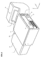
FIG. 1 is a diagram (perspective view) showing an external arrangement of a projector in an embodiment of the present invention; -
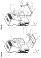
FIGs. 2A and 2B are diagrams explaining an adapter and an installation method of the adapter in the embodiment. -
FIGs. 3A and 3B are diagrams showing a state in use of the projector in the embodiment. -
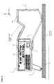
FIG. 4 is a diagram showing the state in use of the projector in the embodiment. -
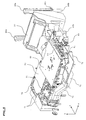
FIG. 5 is a diagram (perspective view) showing an internal arrangement of the projector in the embodiment. -
FIG. 6 is a diagram (top plan view) showing the internal arrangement of the projector in the embodiment. -
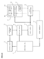
FIG. 7 is a diagram showing a circuit arrangement of the projector in the embodiment. -
FIGs. 8A and 8B are diagrams showing the circuit arrangement of a cutoff circuit and switching circuit in the embodiment. -
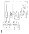
FIG. 9 is a diagram showing a control processing of a buzzer circuit in the embodiment. -
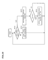
FIG. 10 is a diagram showing a supply operation of a direct-current voltage (hereinafter, referred to as "DC voltage") to an alarm microcomputer and an alarm board in the embodiment. -
FIG. 11 is a diagram showing a modification example of the circuit arrangement of the projector in the embodiment. -
FIG. 12 is a diagram showing another modification example of the circuit arrangement of the projector in the embodiment. - It should be understood that the drawings are only for purpose of description, and do not limit the scope of the present invention.
- A structure of a projector in the embodiments will be explained below with reference to the drawings.
-
FIG 1 is a perspective view showing an external arrangement of the projector. - An
external cabinet 1 of the projector consists of afirst cabinet 1a andsecond cabinet 1b which laterally protrudes from thefirst cabinet 1a. Awindow 2 for projecting light modulated by image signals is arranged on the front-face side of thefirst cabinet 1a. Near thewindow 2, a remotecontroller receiving part 90 faces outside. From the right lateral of the first cabinet la, terminals of anAV terminal part 50 and AC inlet 60 face outside. Aknob 22 for performing focus adjustment of a projection image is arranged on the right lateral of thefirst cabinet 1a. Theknob 22 may be moved in a Z axis direction. -
Operation buttons part 51 for inputting the alarm operation is included in the AVterminal part 50. Moreover, from thesecond cabinet 1b, LED 451 (this will be mentioned later) for reporting a fall of a battery residual quantity faces outside. - An adapter is used when placing the projector on a placing surface such as a floor.
-
FIGs. 2A and 2B are diagrams explaining a structure and a placing method of the adapter.FIG. 2A shows a case where astand 3 is used as the adapter, andFIG. 2B shows a case where anarm member 5 is used as the adapter. - Referring to
FIG. 2A , thestand 3 is mounted onto the bases of thefirst cabinet 1a and thesecond cabinet 1b. That is, with the bases of thefirst cabinet 1a and thesecond cabinet 1b placed on the top face of thestand 3, thestand 3 is fixed to thefirst cabinet 1a withscrews 4. -
FIGs. 3A and 3B are a right side view and rear side view, respectively, showing conditions of a use of the projector when it is equipped with thestand 3. In this case, light modulated by image signals is projected on the face (placing surface) where the projector is placed. - Referring to
FIG. 2B , anarm member 5 is equipped on the rear side of thefirst cabinet 1a and thesecond cabinet 1b. That is, screw holes of the rear side of thefirst cabinet 1a and thesecond cabinet 1b and holes of thearm member 5 are fit together, and thearm member 5 is fixed to thefirst cabinet 1a withscrews 6. -
FIG. 4 is a right side view showing a condition of a use of the projector when it is equipped with thearm member 5. In this case, the light modulated by the image signals is projected on different a face (a wall, a screen, etc.) from the face (placing surface) where the projector is placed. It is noted that, when an adjustingscrew 5a arranged on thearm member 5 is turned, a projection direction of the light is fine-adjusted and a projection condition of an image over a projection surface will be adjusted. -
FIGs. 5 and6 are the external perspective view and top plan view showing the arrangement of the projector in the condition where theexternal cabinet 1 is being omitted. It is noted that,FIG. 6 shows the condition where amain substrate 40 is removed. - Referring to
FIGs. 5 and6 , the projector includes anoptical engine 10, a projectionoptical system 20, apower supply unit 30, themain substrate 40, the AVterminal part 50, and theAC inlet 60. It is noted that, 80a are bosses from a front-face side cabinet, 80b are bosses from a rear-face side cabinet and 80c are bushes for vibration absorption. - Theprojection
optical system 20 is equipped in the cabinet with its brim sandwiched between thebosses bushes 80c. Thus, the projectionoptical system 20 is supported through thebushes 80c for vibration absorption. For this reason, it is difficult for an impact from theexternal cabinet 1 to reach the projectionoptical system 20. Moreover, the projectionoptical system 20 is supported by thebosses 80a from the front-face side cabinet and thebosses 80b from the rear-face side cabinet through thebushes 80c for vibration absorption. This increases the supporting strength to the projectionoptical system 20. - From a projection lens part of the projection
optical system 20, alever 21 for focus adjustment protrudes in the manner shown inFIG. 6 . A focus of a projection image is adjusted by rotating thislever 21 on the X-Z plane. Theknob 22 for the above-mentioned focus adjustment is equipped at the tip of the focusinglever 21. Thisknob 22 faces outside from the right lateral of thefirst cabinet 1a (seeFIG. 4 ). - The
optical engine 10 separates white light from alight source 101 into light of a blue wavelength band, green wavelength band and red wavelength band. The separated light of each wavelength band is modulated by an imager (liquid crystal panel). The modulated light of each wavelength band is combined by a dichroic prism. The combined light is emitted towards the projectionoptical system 20. As shown inFIG. 6 , thelight source 101 is arranged to emit the light in an X axis direction, and the projectionoptical system 20 is arranged to have its optical axis be in a Y axis direction. - The
power supply unit 30 supplies electric power to thelight source 101 and themain substrate 40. AC voltage is inputted into thepower supply unit 30 through theAC inlet 60. Themain substrate 40 is a circuit for driving and controlling the projector. As shown inFIG. 5 , a circuit substrate holding themain substrate 40 is arranged to cover a part of theoptical engine 10. Moreover, AV (Audio Visual) signal is inputted into themain substrate 40 through the AVterminal part 50. Furthermore, theoperation buttons part 51 for inputting the alarm operation is included in the AVterminal part 50, as described above. - It is noted that an alarm circuit is arranged on the
main substrate 40 in this embodiment. Details of the alarm circuit and its peripheral circuit will be explained referring toFIGs. 7 to 9 later. - Three
suction fans 71 are arranged on the rear-face side of theoptical engine 10. Air inhaled with thesesuction fans 71 is exhausted withexhaust fans 72 arranged on the left lateral side of theoptical engine 10 and anexhaust fan 72 arranged on the rear side. By arranging thesuction fans 71 and theexhaust fans 72 as such, the air inhaled with thesuction fan 71 flows through the optical system of theoptical engine 10, thelight source 101 and thepower supply unit 30. Moreover, the inhaled air is led to the side face of thelight source 101 through aduct 73, and flows toward theexhaust fans 72 from the side face of thelight source 101. The heat generated in these members is removed by this flow of the air. - Next, referring to
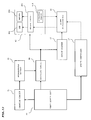
FIG. 7 , the structure of the alarm circuit and its peripheral circuit arranged on the above-mentionedmain substrate 40 is explained. It is noted that thepower supply unit 30 is illustrated together in this drawing for the sake of convenience. - The
power supply unit 30 generates a DC voltage by rectifying the AC voltage inputted through theAC inlet 60, and supplies the generated DC voltage to a chargingcircuit 41, acutoff circuit 43 and asystem controller 47. Thepower supply unit 30 corresponds to the "power supply part" of the present invention. - The charging
circuit 41 charges arechargeable battery 42 using the DC voltage supplied from thepower supply unit 30. Therechargeable battery 42 is a nickel hydride battery, and supplies the charged DC voltage to thecutoff circuit 43. The chargingcircuit 41 corresponds to the "charging part" of the present invention. - The
cutoff circuit 43 comprises a reset IC. When the DC voltage supplied from therechargeable battery 42 is less than a threshold value Vs1, thecutoff circuit 43 cuts off the supply of the DC voltage from therechargeable battery 42 to the switchingcircuit 44. Thecutoff circuit 43 corresponds to the "cutoff part" of the present invention. - The threshold value Vs1 is, for example, set at a lower limit value of a range of the voltage where each circuit on the
alarmboard 45 and thealarmmicrocomputer 46 can operate normally. Thus, when the threshold value Vs1 is set this way, it can be prohibited that the consumption of the voltage from the rechargeable battery by being supplied to thealarm board 45 and thealarmmicrocomputer 46 even though they cannot be operated. Therefore, wasteful discharge of the rechargeable battery withthealarmboard 45 and thealarmmicrocomputer 46 can be suppressed most suitably. - In addition, the threshold value Vs1 may be set at the recommended voltage value which is a predetermined voltage value below which discharge of the
rechargeable battery 42 should be suspended, or the threshold value Vs1 may be set in consideration of both the above-mentioned lower limit value and the recommended voltage value. Thus, setting the threshold value Vs1 in this manner stops the discharge of therechargeable battery 42 before therechargeable battery 42 turns into an overdischarge state. -
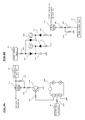
FIG. 8A is a diagram showing the structure of thecutoff circuit 43. - The DC voltage from the
rechargeable battery 42 is inputted into thereset IC 43b through aresistor 43a. Thereset IC 43b sets up the output signal from a first terminal at high-level when the DC voltage supplied from therechargeable battery 42 is the threshold values Vs1 or more. This signal is supplied to a base of atransistor 43d through theresistor 43c. Thereby, thetransistor 43d is turned on. When thetransistor 43d is turned on in this way, current flows through theresistor 43f, 43e and thetransistor 43d from therechargeable battery 42, and a potential difference will arise between the source and gate of aFET 43g. Thereby, theFET 43g is turned on, and the DC voltage from therechargeable battery 42 is supplied to the switchingcircuit 44. - On the other hand, when the DC voltage supplied from the
rechargeable battery 42 is less than the threshold value Vs1, thereset IC 43b brings down the output signal from the first terminal to a low level. Thereby thetransistor 43d is turned off, and the current does not flow through theresistor 43f, 43e andtransistor 43d from therechargeable battery 42. In this case, no potential difference arises between the source and gate of theFET 43g, and, for this reason, theFET 43g is turned off. In this way, the DC voltage from therechargeable battery 42 is no longer supplied to the switchingcircuit 44. - Returning to
FIG. 7 , the switchingcircuit 44 supplies either the DC voltage supplied from thepower supply unit 30 or the DC voltage supplied from therechargeable battery 42 through thecutoff circuit 43 to thealarm board 45 and thealarm microcomputer 46. The switchingcircuit 44 corresponds to the "switching part" of the present invention. -
FIG. 8B is a diagram showing the structure of the switchingcircuit 44. - The DC voltage from the
power supply unit 30 is supplied to adiode 44b,capacitor 44c anddiode 44d through aresistor 44a. At this time, simultaneously, the DC voltage from thepower supply unit 30 is supplied to the gate of aFET 44h throughresisters 44e-44f, and, thereby, theFET 44h is turned OFF. It is noted that an FET which will turn into an OFF state when a high-level signal is supplied to the gate is used for theFET 44h. - Thus, when the
FET 44h is turned off, the DC voltage from thecutoff circuit 43, i.e., the DC voltage from therechargeable battery 42 will be cut off by theFET 44h. Therefore, in this case, the DC voltage supplied through thediodes power supply unit 30 is considered to be the DC voltage (Vcc, Vc) supplied to thealarm board 45 and thealarm microcomputer 46. - On the other hand, when a connection of an outlet (external power supply) to the
AC inlet 60 is removed and the DC voltage is no longer supplied to the switchingcircuit 44 from thepower supply unit 30, the gate of theFET 44h will be connected to ground and theFET 44h will be switched to an ON state. Thereby, the DC voltage from thecutoff circuit 43, i.e., the DC voltage from therechargeable battery 42 is conducted through theFET 44h and supplied todiodes resistors 44i and 44k. Therefore, in this case, the DC voltage supplied from thecutoff circuit 43, i.e., the DC voltage from therechargeable battery 42 is considered to be the DC voltage (Vcc, Vc) supplied to thealarm board 45 and thealarm microcomputer 46. - Thus, the switching
circuit 44 supplies thealarm board 45 and thealarm microcomputer 46 with the DC voltage from thepower supply unit 30 when the DC voltage is supplied therefrom, while supplying the DC voltage from therechargeable battery 42 through thecutoff circuit 43 when no DC voltage is supplied from thepower supply unit 30. - Returning to
FIG. 7 , thealarm board 45 includes an LED (Light Emitting Diode) 451, abuzzer 452, abuzzer circuit 453, and avibration sensor 454. Among these, thebuzzer circuit 453 drives theLED 451 and thebuzzer 452 according to a control signal from thealarm microcomputer 46. Thevibration sensor 454 outputs a detection result (vibration signal) to thealarm microcomputer 46. - The
alarm microcomputer 46 controls and drives thebuzzer circuit 453 by referring to the vibration signal inputted from thevibration sensor 454 and the DC voltage supplied from the switchingcircuit 44. The control processing in thealarm microcomputer 46 is explained by referring toFIG. 9 later. Thealarm board 45 and thealarm microcomputer 46 correspond to the "alarm part" of the present invention. - The
system controller 47 supplies parameter values regarding a sound volume of an alarm (buzzer), a detection sensitivity of the vibration, a duration of an alarm output, etc. to thealarm microcomputer 46. Such parameter values are suitably changed by a user's choice of alarm setting items in a user menu. Moreover, thesystem controller 47 supplies thealarm microcomputer 46 with a signal (hereinafter, referred to as "AC status signal") which shows whether the electric power is supplied from thepower supply unit 30, i.e., whether theAC inlet 60 is connected to the outlet (external power supply). Thealarmmicrocomputer 46 controls and drives thebuzzer circuit 453 based on the parameter values supplied from thesystem controller 47 and on the AC status signal. - Next, referring to
FIG. 9 , the control processing in thealarmmicrocomputer 46 is explained. It is noted that a process flow shown in this diagram is performed when an alarm mode is set by the user through theoperation buttons part 51. - The
alarm microcomputer 46 distinguishes whether the DC voltage is supplied from thepower supply unit 30 based on the AC status signal supplied from the system controller 47 (S101). When the DC voltage is not supplied from the power supply unit 30 (S101: YES), thealarm microcomputer 46 judges that the currently supplied DC voltage is from therechargeable battery 42, and then judges whether the vibration degree Ad detected by thevibration sensor 454 exceeds the threshold value As or not (S102). - If the judgment in S102 is not Ad>As (S102: NO), the
alarm microcomputer 46 will judge whether the DC voltage Vi from therechargeable battery 42 supplied from the switchingcircuit 44 is less than a threshold value Vs2 (Vs2>Vsl) (S103). At this point, in the case of Vi<Vs2 (S103: YES), thealarm microcomputer 46 judges that the DC voltage Vi from therechargeable battery 42 supplied through the switchingcircuit 44 fell, and outputs a control signal for driving theLED 451 and thebuzzer 452 at regular intervals to the buzzer circuit 453 (S104). Thereby, theLED 451 lights up at regular intervals, and the alarm sound is outputted at regular intervals. This information output enables the user to know the fall of the charge residue of therechargeable battery 42. - In this way, when the
AC inlet 60 is connected to an outlet and the DC voltage from thepower supply unit 30 starts to be supplied while theLED 451 lights up and the alarm sound is outputted, the AC status signal showing this status is supplied to thealarm microcomputer 46 from asystem controller 47. In response to this AC status signal (S101: NO), thealarm microcomputer 46 makes thebuzzer circuit 453 stop driving theLED 451 and the buzzer 452 (S105). - On the other hand, when the judgment in S102 is Ad>As (S102:YES), the
alarm microcomputer 46 judges that the projector body is moved (vibrated greatly) and outputs a control signal for driving thebuzzer 452 to the buzzer circuit 453 (S106). Thereby, the alarm sound is outputted from the projector. - It is noted that the detection sensitivity of detecting the movement of the projector is decided by the threshold value As. Here, the threshold value As is set based on a set value of the detection sensitivity of the vibration among the parameter values supplied from the above-mentioned
system controller 47. Moreover, the sound volume and output duration of the alarm sound in S106 are also set based on set values of the parameters supplied from the above-mentionedsystem controller 47. - Once the
buzzer 452 is driven in S106, thealarm microcomputer 46 continues outputting the alarm sound until either elapse of the output duration set by the system controller 47 (S109: YES) or receipt of the AC status signal which shows that theAC inlet 60 is connected to the outlet from a system controller 47 (S110:YES). It is noted that even during output of the alarm, thealarm microcomputer 46 continuously monitors whether the DC voltage Vi from therechargeable battery 42 is less than the threshold value Vs2 (S107). In response to the fall of the DC voltage Vi below the threshold value Vs2 (S107: YES), thealarm microcomputer 46 lights the LED451 at regular intervals (S108). - Thus, after the alarm is outputted, when the output duration of the alarm passes (S109: YES) or the
AC inlet 60 is connected to the outlet (S110: YES), thealarm microcomputer 46 stops the output of the alarm sound (S111). When the alarm output is stopped by connecting theAC inlet 60 to the outlet (S110: YES to S111), after that, until theAC inlet 60 is removed from the outlet (S101: YES), driving of the LED451 and thebuzzer 452 is stopped (S105). On the other hand, when the alarm output is stopped because the duration of the alarm output passes (S109: YES to S111), after that, until theAC inlet 60 is connected to the outlet (S101: NO), processing of after S102 is performed, and as the above, driving of theLED 451 and thebuzzer 452 is performed suitably. - It is noted that, in the process flow of
FIG. 9 , although the alarm output is canceled by the lapse of the alarm output duration (S109) and the connection of theAC inlet 60, the output of the alarm may be canceled by inputting a password. In this case, the password is, for example, entered from theoperation buttons part 51 for inputting the alarm operation arranged on the body cabinet. - Moreover, the output of the alarm may be continued until the
AC inlet 60 is connected to the outlet, even if the alarm output duration elapses. In this case, if theAC inlet 60 is not connected to the outlet, the alarm output is continued until the electric power supply from therechargeable battery 42 is cut off according to the operation flow ofFIG. 10 . - Furthermore, in a condition that the
rechargeable battery 42 is removed or almost being removed, even if theAC inlet 60 is connected to the outlet and the DC voltage is supplied from thepower supply unit 30, the alarm sound may be kept outputting and the alarm output may be prevented from being canceled. In this case, for example, a sensor detects the existence of therechargeable battery 42, and that detection signal is inputted into thesystem controller 47. When thesystem controller 47 judges that therechargeable battery 42 has been removed based on this detection signal, a signal indicating the situation is supplied to thealarm microcomputer 46. In response to this signal, thealarm microcomputer 46 makes thebuzzer circuit 453 drive thebuzzer 452. In this case, even if the AC status signal which shows that there is electric power supply of the DC voltage from thepower supply unit 30 is inputted from thesystem controller 47, thealarm microcomputer 46 makes thebuzzer 452 continue to drive. - Next, referring to
FIG. 10 , a supply operation of the DC voltage to thealarm board 45 and thealarm microcomputer 46 is explained. - When the
AC inlet 60 is connected to the outlet and the DC voltage is supplied from the power supply unit 30 (S201: NO), the switchingcircuit 44 supplies the DC voltage inputted from thepower supply unit 30 to thealarm board 45 and the alarm microcomputer 46 (S202). On the other hand, when the DC voltage is not inputted from the power supply unit 30 (S201: YES), the switchingcircuit 44 supplies the DC voltage supplied from therechargeable battery 42 through thecutoff circuit 43 to thealarm board 45 and thealarm microcomputer 46 instead of the DC voltage inputted from the power supply unit 30 (S203). - While the DC voltage from the
rechargeable battery 42 is supplied to thealarm board 45 and thealarm microcomputer 46, if the DC voltage Vb from therechargeable battery 42 becomes less than the threshold value Vs1 (Vsl<Vs2) (S204: YES), the supply of the DC voltage from therechargeable battery 42 to the switchingcircuit 44 will be cut off by the cutoff circuit 43 (S205). Thereby, after that, the electric power consumption of therechargeable battery 42 by thealarm board 45 and thealarm microcomputer 46 is avoided. Therefore, the situation where therechargeable battery 42 falls in an overdischarge state is avoided, and degradation and a fall of charging capacity of therechargeable battery 42 are prevented. - When the
AC inlet 60 is connected to the outlet and the electric power supply from thepower supply unit 30 is resumed after an appropriate time (S201: NO), the switchingcircuit 44 supplies the DC voltage inputted from thepower supply unit 30 to thealarm board 45 and the alarm microcomputer 46 (S202). Then, when charging of therechargeable battery 42 progresses and the DC voltage Vb from therechargeable battery 42 becomes the threshold value Vs1 or more (S204: NO), the DC voltage Vb from therechargeable battery 42 starts again to be supplied to the switchingcircuit 44 through thecutoff circuit 43. Therefore, after that, even if the electric power supply from thepower supply unit 30 is stopped (S201: YES), the DC voltage Vb from therechargeable battery 42 starts to be supplied to thealarm board 45 and the alarm microcomputer 46 (S204: NO). - According to the embodiments mentioned above, while the electric power is supplied from the
rechargeable battery 42 to thealarm board 45 and thealarm microcomputer 46, if the DC voltage Vb from therechargeable battery 42 becomes less than the threshold value Vs1, the supply of the DC voltage from therechargeable battery 42 will be cut off. Therefore, after the DC voltage Vb becomes less than the threshold value Vs1, the electric power consumption of therechargeable battery 42 by thealarm board 45 and thealarm microcomputer 46 is avoided. Thus, the situation therechargeable battery 42 fell into the state of overdischarge can be avoided, with the result that degradation or a situation where charging is incapable that therechargeable battery 42 is prevented. - Moreover, since the
cutoff circuit 43 is arranged between therechargeable battery 42 and the switchingcircuit 44 according to the embodiment, when thecutoff circuit 43 operates, the electric power of therechargeable battery 42 can be prevented from being consumed by the switchingcircuit 44 besides thealarm board 45 and thealarm microcomputer 46, and the wasteful discharge of therechargeable battery 42 can be suppressed more effectively. - Thepresent invention is not limited to the above-mentioned embodiments at all, and various alterations are also possible for the embodiments of the present invention in addition to the above embodiments.
- For example, in the above-mentioned embodiments, although the
cutoff circuit 43 has been arranged between therechargeable battery 42 and the switchingcircuit 44, thecutoff circuit 43 may also be arranged in other locations between therechargeable battery 42 and thealarm microcomputer 46. -
FIG. 11 shows an example of a structure of a case arranging thecutoff circuit 43 just behind the switchingcircuit 44. Also in this example of the structure, if the DC voltage Vb from therechargeable battery 42 becomes less than the threshold value Vs1 while therechargeable battery 42 is in use, the electric power supply to thealarm board 45 and thealarm microcomputer 46 will be cut off by thecutoff circuit 43. Thus, the situation where therechargeable battery 42 fell into the state of overdischarge can be avoided, and degradation or a situation where charging is incapable for therechargeable battery 42 is prevented. -
FIG. 12 shows an example of a structure of a case arranging thecutoff circuit 43 just before thealarm microcomputer 46. In this example of the structure, if the DC voltage Vb from therechargeable battery 42 becomes less than the threshold value Vs1 while therechargeable battery 42 is in use, the electric power supply to thealarm microcomputer 46 will be cut off by thecutoff circuit 43. In this case, the electric power from therechargeable battery 42 is connected to thealarm board 45. However, if the DC voltage Vb from therechargeable battery 42 becomes less than the threshold value Vs1, the electric power supply to thealarm microcomputer 46 is cut off, and thealarm microcomputer 46 will be in a turned off state; therefore, thebuzzer circuit 453 will not operate after that. Thus, also in this case, the situation where therechargeable battery 42 falls into the state of overdischarge can be avoided, and degradation or a situation where charging is incapable for therechargeable battery 42 is prevented. - In addition, the embodiments of the present invention can be modified in various manners as appropriate, within the scope of technical ideas defined by the claims.
Claims (5)
- A projection display device, comprising:a power supply part which supplies electric power from an external power supply;a charging part which charges a rechargeable battery with the power supply part;an alarm part for outputting an alarm sound;a switching part which supplies either one of the electric power from the power supply part or an electric power from the rechargeable battery to the alarm part; anda cutoff part which cuts off a supply of the electric power from the rechargeable battery to the alarm part when a charge quantity of the rechargeable battery becomes less than a threshold value.
- The projection display device according to Claim 1, wherein
the cutoff part is arranged between the rechargeable battery and the switching part. - The projection display device according to Claim 1 or 2, wherein
the threshold value is set at a lower limit value of a voltage range where the alarm part can operate normally. - The projection display device according to Claim 1 or 2, wherein
the threshold value is set at a voltage value which is determined beforehand to suspend discharge of the rechargeable battery. - The projection display device according to any one of Claims 1 to 4, wherein
the alarm part has a distinguish part for distinguishing whether the projection display device is moved, and outputs the alarm sound when an electric power from the rechargeable battery is supplied to the alarm part by the switching part, and when the distinguish part determines that the projection display device is moved.
Applications Claiming Priority (1)
| Application Number | Priority Date | Filing Date | Title |
|---|---|---|---|
| JP2008219975A JP2010055394A (en) | 2008-08-28 | 2008-08-28 | Projection video display device |
Publications (2)
| Publication Number | Publication Date |
|---|---|
| EP2159636A1 true EP2159636A1 (en) | 2010-03-03 |
| EP2159636B1 EP2159636B1 (en) | 2010-12-08 |
Family
ID=41217530
Family Applications (1)
| Application Number | Title | Priority Date | Filing Date |
|---|---|---|---|
| EP09011006A Not-in-force EP2159636B1 (en) | 2008-08-28 | 2009-08-27 | Projection display device with theft protection |
Country Status (5)
| Country | Link |
|---|---|
| US (1) | US20100052926A1 (en) |
| EP (1) | EP2159636B1 (en) |
| JP (1) | JP2010055394A (en) |
| AT (1) | ATE491169T1 (en) |
| DE (1) | DE602009000438D1 (en) |
Cited By (1)
| Publication number | Priority date | Publication date | Assignee | Title |
|---|---|---|---|---|
| CN105939039A (en) * | 2016-06-20 | 2016-09-14 | 深圳天珑无线科技有限公司 | Over-discharge early-warning circuit for battery and electronic equipment |
Families Citing this family (4)
| Publication number | Priority date | Publication date | Assignee | Title |
|---|---|---|---|---|
| TWI537673B (en) * | 2014-04-30 | 2016-06-11 | 中強光電股份有限公司 | Optical projection system and energy control method therefor |
| CN110067971B (en) | 2014-12-26 | 2021-08-27 | 麦克赛尔株式会社 | Lighting device |
| CN105353576A (en) * | 2015-11-25 | 2016-02-24 | 广景视睿科技(深圳)有限公司 | Projector |
| JP7757826B2 (en) * | 2022-02-18 | 2025-10-22 | セイコーエプソン株式会社 | projector |
Citations (6)
| Publication number | Priority date | Publication date | Assignee | Title |
|---|---|---|---|---|
| WO1990012427A1 (en) * | 1989-03-30 | 1990-10-18 | Tellio Joseph Grilli | Energy monitor for storage cells |
| US5747189A (en) * | 1992-07-22 | 1998-05-05 | Valence Technology, Inc. | Smart battery |
| WO1998036483A1 (en) * | 1997-01-27 | 1998-08-20 | Nokia Telecommunications Oy | Circuit arrangement for preventing deep discharge of a battery |
| US20060164242A1 (en) * | 2005-01-25 | 2006-07-27 | Nec Viewtechnology, Ltd. | Projector device with theft prevention function and theft preventing method |
| US20080088446A1 (en) * | 2006-10-12 | 2008-04-17 | Sanyo Electric Co., Ltd. | Image display device |
| JP2008219975A (en) | 2007-02-28 | 2008-09-18 | Mitsubishi Heavy Ind Ltd | Cogeneration apparatus and method for confirming wiring of current detection means in cogeneration apparatus |
Family Cites Families (11)
| Publication number | Priority date | Publication date | Assignee | Title |
|---|---|---|---|---|
| JPS6249494A (en) * | 1985-08-28 | 1987-03-04 | シャープ株式会社 | Invasion alarm using battery power source |
| US5999094A (en) * | 1986-10-22 | 1999-12-07 | Nilssen; Ole K. | Combination telephone and smoke alarm system |
| JPH0251797A (en) * | 1988-08-15 | 1990-02-21 | Sharp Corp | Terminal controller |
| US5574436A (en) * | 1993-07-21 | 1996-11-12 | Sisselman; Ronald | Smoke detector including an indicator for indicating a missing primary power source which is powered by a substantially nonremovable secondary power source |
| JP3080544B2 (en) * | 1994-09-20 | 2000-08-28 | 三菱電機株式会社 | Portable electronic devices |
| US5638046A (en) * | 1995-02-13 | 1997-06-10 | Malinowski; Robert | Security system |
| JP3700749B2 (en) * | 1998-03-19 | 2005-09-28 | 富士電機リテイルシステムズ株式会社 | vending machine |
| JP2001268820A (en) * | 2000-03-17 | 2001-09-28 | Nittan Co Ltd | Spare battery charging circuit |
| JP2003226209A (en) * | 2002-02-06 | 2003-08-12 | Yazaki Corp | Power supply system for vehicles |
| US6917298B2 (en) * | 2002-04-02 | 2005-07-12 | William P. Romano | Solar system alarm backup unit |
| US7482940B2 (en) * | 2002-06-24 | 2009-01-27 | Angeleye Inc. | Alarm for detecting radiation and pollutants |
-
2008
- 2008-08-28 JP JP2008219975A patent/JP2010055394A/en active Pending
-
2009
- 2009-08-27 EP EP09011006A patent/EP2159636B1/en not_active Not-in-force
- 2009-08-27 AT AT09011006T patent/ATE491169T1/en not_active IP Right Cessation
- 2009-08-27 DE DE602009000438T patent/DE602009000438D1/en active Active
- 2009-08-27 US US12/549,216 patent/US20100052926A1/en not_active Abandoned
Patent Citations (6)
| Publication number | Priority date | Publication date | Assignee | Title |
|---|---|---|---|---|
| WO1990012427A1 (en) * | 1989-03-30 | 1990-10-18 | Tellio Joseph Grilli | Energy monitor for storage cells |
| US5747189A (en) * | 1992-07-22 | 1998-05-05 | Valence Technology, Inc. | Smart battery |
| WO1998036483A1 (en) * | 1997-01-27 | 1998-08-20 | Nokia Telecommunications Oy | Circuit arrangement for preventing deep discharge of a battery |
| US20060164242A1 (en) * | 2005-01-25 | 2006-07-27 | Nec Viewtechnology, Ltd. | Projector device with theft prevention function and theft preventing method |
| US20080088446A1 (en) * | 2006-10-12 | 2008-04-17 | Sanyo Electric Co., Ltd. | Image display device |
| JP2008219975A (en) | 2007-02-28 | 2008-09-18 | Mitsubishi Heavy Ind Ltd | Cogeneration apparatus and method for confirming wiring of current detection means in cogeneration apparatus |
Cited By (1)
| Publication number | Priority date | Publication date | Assignee | Title |
|---|---|---|---|---|
| CN105939039A (en) * | 2016-06-20 | 2016-09-14 | 深圳天珑无线科技有限公司 | Over-discharge early-warning circuit for battery and electronic equipment |
Also Published As
| Publication number | Publication date |
|---|---|
| EP2159636B1 (en) | 2010-12-08 |
| US20100052926A1 (en) | 2010-03-04 |
| JP2010055394A (en) | 2010-03-11 |
| DE602009000438D1 (en) | 2011-01-20 |
| ATE491169T1 (en) | 2010-12-15 |
Similar Documents
| Publication | Publication Date | Title |
|---|---|---|
| EP2159636B1 (en) | Projection display device with theft protection | |
| US6588907B1 (en) | Self-contained cool-down system for a video projector | |
| KR101315645B1 (en) | Dual battery control system and method thereof | |
| US20080174279A1 (en) | Battery charging system and method thereof | |
| CN101064441A (en) | Charging device for battery | |
| US8473112B2 (en) | Battery pack, electronic equipment, equipment system, method for controlling battery pack cooling unit, and program | |
| JP2013102649A (en) | Battery pack | |
| US20080113691A1 (en) | Charge Control Apparatus and Charge Control Method For Portable Telephone Terminal | |
| US20240387888A1 (en) | Battery pack and electrical device | |
| US7911531B2 (en) | Battery, camera and camera system | |
| KR100584324B1 (en) | Power control device of composite terminal | |
| JP2914425B2 (en) | Mobile phone with automatic power control function | |
| KR20180136066A (en) | Navigation device performing a navigtion function and a tablet computer function and navigation system including the same | |
| US20040164714A1 (en) | AC adaptor | |
| JP2007088535A (en) | Charging stand apparatus and program | |
| CN2657568Y (en) | Charging type vacuum cleaner | |
| JP2013142845A (en) | Electronic device | |
| KR100557163B1 (en) | Apparatus and method for implementing an alarm function in a charging device of a mobile terminal | |
| US20020118968A1 (en) | Electric power control device for camera | |
| JP2001174888A (en) | camera | |
| KR20030072027A (en) | Portable electronic device enable to charge and discharge battery | |
| CN114076591A (en) | Laser level meter | |
| EP1484909B1 (en) | Camera control device and digital still camera | |
| KR100222709B1 (en) | A portable vacuum cleaner | |
| JP2004057367A (en) | Electric vacuum cleaner |
Legal Events
| Date | Code | Title | Description |
|---|---|---|---|
| PUAI | Public reference made under article 153(3) epc to a published international application that has entered the european phase |
Free format text: ORIGINAL CODE: 0009012 |
|
| 17P | Request for examination filed |
Effective date: 20091217 |
|
| AK | Designated contracting states |
Kind code of ref document: A1 Designated state(s): AT BE BG CH CY CZ DE DK EE ES FI FR GB GR HR HU IE IS IT LI LT LU LV MC MK MT NL NO PL PT RO SE SI SK SM TR |
|
| AX | Request for extension of the european patent |
Extension state: AL BA RS |
|
| GRAJ | Information related to disapproval of communication of intention to grant by the applicant or resumption of examination proceedings by the epo deleted |
Free format text: ORIGINAL CODE: EPIDOSDIGR1 |
|
| GRAP | Despatch of communication of intention to grant a patent |
Free format text: ORIGINAL CODE: EPIDOSNIGR1 |
|
| GRAP | Despatch of communication of intention to grant a patent |
Free format text: ORIGINAL CODE: EPIDOSNIGR1 |
|
| RIN1 | Information on inventor provided before grant (corrected) |
Inventor name: OKU, MASAKI |
|
| RAP1 | Party data changed (applicant data changed or rights of an application transferred) |
Owner name: SANYO ELECTRIC CO., LTD. |
|
| GRAS | Grant fee paid |
Free format text: ORIGINAL CODE: EPIDOSNIGR3 |
|
| GRAA | (expected) grant |
Free format text: ORIGINAL CODE: 0009210 |
|
| AK | Designated contracting states |
Kind code of ref document: B1 Designated state(s): AT BE BG CH CY CZ DE DK EE ES FI FR GB GR HR HU IE IS IT LI LT LU LV MC MK MT NL NO PL PT RO SE SI SK SM TR |
|
| REG | Reference to a national code |
Ref country code: GB Ref legal event code: FG4D |
|
| REG | Reference to a national code |
Ref country code: CH Ref legal event code: EP |
|
| REG | Reference to a national code |
Ref country code: IE Ref legal event code: FG4D |
|
| REF | Corresponds to: |
Ref document number: 602009000438 Country of ref document: DE Date of ref document: 20110120 Kind code of ref document: P |
|
| REG | Reference to a national code |
Ref country code: NL Ref legal event code: VDEP Effective date: 20101208 |
|
| PG25 | Lapsed in a contracting state [announced via postgrant information from national office to epo] |
Ref country code: LT Free format text: LAPSE BECAUSE OF FAILURE TO SUBMIT A TRANSLATION OF THE DESCRIPTION OR TO PAY THE FEE WITHIN THE PRESCRIBED TIME-LIMIT Effective date: 20101208 Ref country code: NO Free format text: LAPSE BECAUSE OF FAILURE TO SUBMIT A TRANSLATION OF THE DESCRIPTION OR TO PAY THE FEE WITHIN THE PRESCRIBED TIME-LIMIT Effective date: 20110308 |
|
| LTIE | Lt: invalidation of european patent or patent extension |
Effective date: 20101208 |
|
| PG25 | Lapsed in a contracting state [announced via postgrant information from national office to epo] |
Ref country code: FI Free format text: LAPSE BECAUSE OF FAILURE TO SUBMIT A TRANSLATION OF THE DESCRIPTION OR TO PAY THE FEE WITHIN THE PRESCRIBED TIME-LIMIT Effective date: 20101208 Ref country code: LV Free format text: LAPSE BECAUSE OF FAILURE TO SUBMIT A TRANSLATION OF THE DESCRIPTION OR TO PAY THE FEE WITHIN THE PRESCRIBED TIME-LIMIT Effective date: 20101208 Ref country code: SI Free format text: LAPSE BECAUSE OF FAILURE TO SUBMIT A TRANSLATION OF THE DESCRIPTION OR TO PAY THE FEE WITHIN THE PRESCRIBED TIME-LIMIT Effective date: 20101208 Ref country code: SE Free format text: LAPSE BECAUSE OF FAILURE TO SUBMIT A TRANSLATION OF THE DESCRIPTION OR TO PAY THE FEE WITHIN THE PRESCRIBED TIME-LIMIT Effective date: 20101208 Ref country code: BG Free format text: LAPSE BECAUSE OF FAILURE TO SUBMIT A TRANSLATION OF THE DESCRIPTION OR TO PAY THE FEE WITHIN THE PRESCRIBED TIME-LIMIT Effective date: 20110308 Ref country code: CY Free format text: LAPSE BECAUSE OF FAILURE TO SUBMIT A TRANSLATION OF THE DESCRIPTION OR TO PAY THE FEE WITHIN THE PRESCRIBED TIME-LIMIT Effective date: 20101208 Ref country code: NL Free format text: LAPSE BECAUSE OF FAILURE TO SUBMIT A TRANSLATION OF THE DESCRIPTION OR TO PAY THE FEE WITHIN THE PRESCRIBED TIME-LIMIT Effective date: 20101208 Ref country code: HR Free format text: LAPSE BECAUSE OF FAILURE TO SUBMIT A TRANSLATION OF THE DESCRIPTION OR TO PAY THE FEE WITHIN THE PRESCRIBED TIME-LIMIT Effective date: 20101208 Ref country code: AT Free format text: LAPSE BECAUSE OF FAILURE TO SUBMIT A TRANSLATION OF THE DESCRIPTION OR TO PAY THE FEE WITHIN THE PRESCRIBED TIME-LIMIT Effective date: 20101208 |
|
| PG25 | Lapsed in a contracting state [announced via postgrant information from national office to epo] |
Ref country code: ES Free format text: LAPSE BECAUSE OF FAILURE TO SUBMIT A TRANSLATION OF THE DESCRIPTION OR TO PAY THE FEE WITHIN THE PRESCRIBED TIME-LIMIT Effective date: 20110319 Ref country code: EE Free format text: LAPSE BECAUSE OF FAILURE TO SUBMIT A TRANSLATION OF THE DESCRIPTION OR TO PAY THE FEE WITHIN THE PRESCRIBED TIME-LIMIT Effective date: 20101208 Ref country code: PT Free format text: LAPSE BECAUSE OF FAILURE TO SUBMIT A TRANSLATION OF THE DESCRIPTION OR TO PAY THE FEE WITHIN THE PRESCRIBED TIME-LIMIT Effective date: 20110408 Ref country code: GR Free format text: LAPSE BECAUSE OF FAILURE TO SUBMIT A TRANSLATION OF THE DESCRIPTION OR TO PAY THE FEE WITHIN THE PRESCRIBED TIME-LIMIT Effective date: 20110309 Ref country code: CZ Free format text: LAPSE BECAUSE OF FAILURE TO SUBMIT A TRANSLATION OF THE DESCRIPTION OR TO PAY THE FEE WITHIN THE PRESCRIBED TIME-LIMIT Effective date: 20101208 Ref country code: IS Free format text: LAPSE BECAUSE OF FAILURE TO SUBMIT A TRANSLATION OF THE DESCRIPTION OR TO PAY THE FEE WITHIN THE PRESCRIBED TIME-LIMIT Effective date: 20110408 Ref country code: BE Free format text: LAPSE BECAUSE OF FAILURE TO SUBMIT A TRANSLATION OF THE DESCRIPTION OR TO PAY THE FEE WITHIN THE PRESCRIBED TIME-LIMIT Effective date: 20101208 |
|
| PG25 | Lapsed in a contracting state [announced via postgrant information from national office to epo] |
Ref country code: SK Free format text: LAPSE BECAUSE OF FAILURE TO SUBMIT A TRANSLATION OF THE DESCRIPTION OR TO PAY THE FEE WITHIN THE PRESCRIBED TIME-LIMIT Effective date: 20101208 Ref country code: PL Free format text: LAPSE BECAUSE OF FAILURE TO SUBMIT A TRANSLATION OF THE DESCRIPTION OR TO PAY THE FEE WITHIN THE PRESCRIBED TIME-LIMIT Effective date: 20101208 Ref country code: RO Free format text: LAPSE BECAUSE OF FAILURE TO SUBMIT A TRANSLATION OF THE DESCRIPTION OR TO PAY THE FEE WITHIN THE PRESCRIBED TIME-LIMIT Effective date: 20101208 |
|
| PLBE | No opposition filed within time limit |
Free format text: ORIGINAL CODE: 0009261 |
|
| STAA | Information on the status of an ep patent application or granted ep patent |
Free format text: STATUS: NO OPPOSITION FILED WITHIN TIME LIMIT |
|
| PG25 | Lapsed in a contracting state [announced via postgrant information from national office to epo] |
Ref country code: DK Free format text: LAPSE BECAUSE OF FAILURE TO SUBMIT A TRANSLATION OF THE DESCRIPTION OR TO PAY THE FEE WITHIN THE PRESCRIBED TIME-LIMIT Effective date: 20101208 |
|
| 26N | No opposition filed |
Effective date: 20110909 |
|
| PG25 | Lapsed in a contracting state [announced via postgrant information from national office to epo] |
Ref country code: MT Free format text: LAPSE BECAUSE OF FAILURE TO SUBMIT A TRANSLATION OF THE DESCRIPTION OR TO PAY THE FEE WITHIN THE PRESCRIBED TIME-LIMIT Effective date: 20101208 Ref country code: IT Free format text: LAPSE BECAUSE OF FAILURE TO SUBMIT A TRANSLATION OF THE DESCRIPTION OR TO PAY THE FEE WITHIN THE PRESCRIBED TIME-LIMIT Effective date: 20101208 |
|
| REG | Reference to a national code |
Ref country code: DE Ref legal event code: R097 Ref document number: 602009000438 Country of ref document: DE Effective date: 20110909 |
|
| PG25 | Lapsed in a contracting state [announced via postgrant information from national office to epo] |
Ref country code: MC Free format text: LAPSE BECAUSE OF NON-PAYMENT OF DUE FEES Effective date: 20110831 |
|
| REG | Reference to a national code |
Ref country code: FR Ref legal event code: ST Effective date: 20120430 |
|
| REG | Reference to a national code |
Ref country code: IE Ref legal event code: MM4A |
|
| PG25 | Lapsed in a contracting state [announced via postgrant information from national office to epo] |
Ref country code: IE Free format text: LAPSE BECAUSE OF NON-PAYMENT OF DUE FEES Effective date: 20110827 |
|
| PG25 | Lapsed in a contracting state [announced via postgrant information from national office to epo] |
Ref country code: FR Free format text: LAPSE BECAUSE OF NON-PAYMENT OF DUE FEES Effective date: 20110831 |
|
| PG25 | Lapsed in a contracting state [announced via postgrant information from national office to epo] |
Ref country code: MK Free format text: LAPSE BECAUSE OF FAILURE TO SUBMIT A TRANSLATION OF THE DESCRIPTION OR TO PAY THE FEE WITHIN THE PRESCRIBED TIME-LIMIT Effective date: 20101208 |
|
| PG25 | Lapsed in a contracting state [announced via postgrant information from national office to epo] |
Ref country code: SM Free format text: LAPSE BECAUSE OF FAILURE TO SUBMIT A TRANSLATION OF THE DESCRIPTION OR TO PAY THE FEE WITHIN THE PRESCRIBED TIME-LIMIT Effective date: 20101208 |
|
| PG25 | Lapsed in a contracting state [announced via postgrant information from national office to epo] |
Ref country code: LU Free format text: LAPSE BECAUSE OF NON-PAYMENT OF DUE FEES Effective date: 20110827 |
|
| REG | Reference to a national code |
Ref country code: GB Ref legal event code: 746 Effective date: 20130617 |
|
| PG25 | Lapsed in a contracting state [announced via postgrant information from national office to epo] |
Ref country code: TR Free format text: LAPSE BECAUSE OF FAILURE TO SUBMIT A TRANSLATION OF THE DESCRIPTION OR TO PAY THE FEE WITHIN THE PRESCRIBED TIME-LIMIT Effective date: 20101208 |
|
| PG25 | Lapsed in a contracting state [announced via postgrant information from national office to epo] |
Ref country code: HU Free format text: LAPSE BECAUSE OF FAILURE TO SUBMIT A TRANSLATION OF THE DESCRIPTION OR TO PAY THE FEE WITHIN THE PRESCRIBED TIME-LIMIT Effective date: 20101208 |
|
| REG | Reference to a national code |
Ref country code: DE Ref legal event code: R084 Ref document number: 602009000438 Country of ref document: DE Effective date: 20130612 |
|
| REG | Reference to a national code |
Ref country code: CH Ref legal event code: PL |
|
| PG25 | Lapsed in a contracting state [announced via postgrant information from national office to epo] |
Ref country code: LI Free format text: LAPSE BECAUSE OF NON-PAYMENT OF DUE FEES Effective date: 20130831 Ref country code: CH Free format text: LAPSE BECAUSE OF NON-PAYMENT OF DUE FEES Effective date: 20130831 |
|
| PGFP | Annual fee paid to national office [announced via postgrant information from national office to epo] |
Ref country code: GB Payment date: 20160824 Year of fee payment: 8 Ref country code: DE Payment date: 20160823 Year of fee payment: 8 |
|
| REG | Reference to a national code |
Ref country code: DE Ref legal event code: R119 Ref document number: 602009000438 Country of ref document: DE |
|
| GBPC | Gb: european patent ceased through non-payment of renewal fee |
Effective date: 20170827 |
|
| PG25 | Lapsed in a contracting state [announced via postgrant information from national office to epo] |
Ref country code: GB Free format text: LAPSE BECAUSE OF NON-PAYMENT OF DUE FEES Effective date: 20170827 Ref country code: DE Free format text: LAPSE BECAUSE OF NON-PAYMENT OF DUE FEES Effective date: 20180301 |