EP2159614A1 - Flame-retardant fiber optic assembly - Google Patents
Flame-retardant fiber optic assembly Download PDFInfo
- Publication number
- EP2159614A1 EP2159614A1 EP09010649A EP09010649A EP2159614A1 EP 2159614 A1 EP2159614 A1 EP 2159614A1 EP 09010649 A EP09010649 A EP 09010649A EP 09010649 A EP09010649 A EP 09010649A EP 2159614 A1 EP2159614 A1 EP 2159614A1
- Authority
- EP
- European Patent Office
- Prior art keywords
- fiber optic
- heat
- flame
- transition location
- optic assembly
- Prior art date
- Legal status (The legal status is an assumption and is not a legal conclusion. Google has not performed a legal analysis and makes no representation as to the accuracy of the status listed.)
- Granted
Links
- 239000000835 fiber Substances 0.000 title claims abstract description 52
- RNFJDJUURJAICM-UHFFFAOYSA-N 2,2,4,4,6,6-hexaphenoxy-1,3,5-triaza-2$l^{5},4$l^{5},6$l^{5}-triphosphacyclohexa-1,3,5-triene Chemical compound N=1P(OC=2C=CC=CC=2)(OC=2C=CC=CC=2)=NP(OC=2C=CC=CC=2)(OC=2C=CC=CC=2)=NP=1(OC=1C=CC=CC=1)OC1=CC=CC=C1 RNFJDJUURJAICM-UHFFFAOYSA-N 0.000 title claims abstract description 27
- 239000003063 flame retardant Substances 0.000 title claims abstract description 27
- 230000007704 transition Effects 0.000 claims abstract description 42
- 239000000463 material Substances 0.000 claims abstract description 21
- 239000011888 foil Substances 0.000 claims abstract description 19
- 239000010445 mica Substances 0.000 claims abstract description 18
- 229910052618 mica group Inorganic materials 0.000 claims abstract description 18
- 229910052751 metal Inorganic materials 0.000 claims abstract description 14
- 239000002184 metal Substances 0.000 claims abstract description 14
- 239000002131 composite material Substances 0.000 claims abstract description 9
- 238000000034 method Methods 0.000 claims description 12
- 230000004888 barrier function Effects 0.000 claims 2
- 230000000712 assembly Effects 0.000 abstract description 14
- 238000000429 assembly Methods 0.000 abstract description 14
- 238000007789 sealing Methods 0.000 abstract description 6
- 239000002356 single layer Substances 0.000 abstract description 2
- 239000000758 substrate Substances 0.000 abstract description 2
- 229910052782 aluminium Inorganic materials 0.000 description 11
- XAGFODPZIPBFFR-UHFFFAOYSA-N aluminium Chemical compound [Al] XAGFODPZIPBFFR-UHFFFAOYSA-N 0.000 description 11
- 239000013307 optical fiber Substances 0.000 description 8
- 239000010410 layer Substances 0.000 description 6
- 239000000779 smoke Substances 0.000 description 6
- 239000000853 adhesive Substances 0.000 description 4
- 230000001070 adhesive effect Effects 0.000 description 4
- 238000010276 construction Methods 0.000 description 4
- 238000012986 modification Methods 0.000 description 4
- 230000004048 modification Effects 0.000 description 4
- 239000004812 Fluorinated ethylene propylene Substances 0.000 description 3
- 230000000694 effects Effects 0.000 description 3
- 239000003292 glue Substances 0.000 description 3
- 238000010438 heat treatment Methods 0.000 description 3
- 238000004519 manufacturing process Methods 0.000 description 3
- 239000002245 particle Substances 0.000 description 3
- 229920009441 perflouroethylene propylene Polymers 0.000 description 3
- 238000012360 testing method Methods 0.000 description 3
- 239000012790 adhesive layer Substances 0.000 description 2
- 239000000203 mixture Substances 0.000 description 2
- 230000003287 optical effect Effects 0.000 description 2
- 229920000098 polyolefin Polymers 0.000 description 2
- 230000001681 protective effect Effects 0.000 description 2
- 238000006467 substitution reaction Methods 0.000 description 2
- 241000723418 Carya Species 0.000 description 1
- RYGMFSIKBFXOCR-UHFFFAOYSA-N Copper Chemical compound [Cu] RYGMFSIKBFXOCR-UHFFFAOYSA-N 0.000 description 1
- 229910000831 Steel Inorganic materials 0.000 description 1
- 229920006362 Teflon® Polymers 0.000 description 1
- 239000004760 aramid Substances 0.000 description 1
- 229920003235 aromatic polyamide Polymers 0.000 description 1
- 238000006243 chemical reaction Methods 0.000 description 1
- 239000011248 coating agent Substances 0.000 description 1
- 238000000576 coating method Methods 0.000 description 1
- 238000002485 combustion reaction Methods 0.000 description 1
- 239000004020 conductor Substances 0.000 description 1
- 229910052802 copper Inorganic materials 0.000 description 1
- 239000010949 copper Substances 0.000 description 1
- 238000013461 design Methods 0.000 description 1
- 230000007613 environmental effect Effects 0.000 description 1
- HQQADJVZYDDRJT-UHFFFAOYSA-N ethene;prop-1-ene Chemical group C=C.CC=C HQQADJVZYDDRJT-UHFFFAOYSA-N 0.000 description 1
- 229920002313 fluoropolymer Polymers 0.000 description 1
- 239000004811 fluoropolymer Substances 0.000 description 1
- 230000002401 inhibitory effect Effects 0.000 description 1
- 238000013508 migration Methods 0.000 description 1
- 230000005012 migration Effects 0.000 description 1
- 229920001084 poly(chloroprene) Polymers 0.000 description 1
- 229920002627 poly(phosphazenes) Polymers 0.000 description 1
- 229920001343 polytetrafluoroethylene Polymers 0.000 description 1
- 239000004810 polytetrafluoroethylene Substances 0.000 description 1
- 229920002635 polyurethane Polymers 0.000 description 1
- 239000004814 polyurethane Substances 0.000 description 1
- 229920000915 polyvinyl chloride Polymers 0.000 description 1
- 230000008569 process Effects 0.000 description 1
- 230000001012 protector Effects 0.000 description 1
- 229920002379 silicone rubber Polymers 0.000 description 1
- 239000007787 solid Substances 0.000 description 1
- 239000007921 spray Substances 0.000 description 1
- 229910001220 stainless steel Inorganic materials 0.000 description 1
- 239000010935 stainless steel Substances 0.000 description 1
- 239000010959 steel Substances 0.000 description 1
- 238000012546 transfer Methods 0.000 description 1
Images



Classifications
-
- G—PHYSICS
- G02—OPTICS
- G02B—OPTICAL ELEMENTS, SYSTEMS OR APPARATUS
- G02B6/00—Light guides; Structural details of arrangements comprising light guides and other optical elements, e.g. couplings
- G02B6/24—Coupling light guides
- G02B6/255—Splicing of light guides, e.g. by fusion or bonding
- G02B6/2558—Reinforcement of splice joint
-
- G—PHYSICS
- G02—OPTICS
- G02B—OPTICAL ELEMENTS, SYSTEMS OR APPARATUS
- G02B6/00—Light guides; Structural details of arrangements comprising light guides and other optical elements, e.g. couplings
- G02B6/44—Mechanical structures for providing tensile strength and external protection for fibres, e.g. optical transmission cables
- G02B6/4401—Optical cables
- G02B6/4429—Means specially adapted for strengthening or protecting the cables
- G02B6/4436—Heat resistant
-
- G—PHYSICS
- G02—OPTICS
- G02B—OPTICAL ELEMENTS, SYSTEMS OR APPARATUS
- G02B6/00—Light guides; Structural details of arrangements comprising light guides and other optical elements, e.g. couplings
- G02B6/44—Mechanical structures for providing tensile strength and external protection for fibres, e.g. optical transmission cables
- G02B6/4439—Auxiliary devices
- G02B6/4471—Terminating devices ; Cable clamps
- G02B6/4476—Terminating devices ; Cable clamps with heat-shrinkable elements
Definitions
- the disclosure is directed to flame-retardant fiber optic assemblies. More specifically, the disclosure is directed to fiber optic assemblies having transition locations that are flame-retardant for indoor or indoor/outdoor use.
- Fiber optic cables developed for indoor or indoor/outdoor use are required to meet stringent flame and/or smoke ratings, which are tested by independent laboratories.
- indoor or indoor/outdoor fiber optic cables are preconnectorized at respective ends with conventional fiber optic connectors and these assemblies meet the desired ratings for the space without modification.
- optical fiber moves toward the subscriber and private networks become more advanced, there is a need for more robust and ruggedized fiber optic assemblies to interface with the emerging plug and play networks deployed for indoor and indoor/outdoor applications.
- the disclosure is directed to various embodiments and methods for fiber optic assemblies having a covering that is flame-retardant for use at a transition location or the like.
- the covering has multiple components and provides the necessary characteristics to pass bum testing, thereby allowing indoor and/or indoor/outdoor use.
- the covering includes a heat dissipative structure and a heat resistant structure disposed about a transition location of the fiber optic assembly.
- the covering may include an optional flame-retardant wrap configured for sealing and/or securing the covering such as a flame-retardant heat-shrink material.
- the heat dissipative structure is a foil, such as an aluminum foil and the heat resistant structure is made of mica, but other materials are possible.
- the covering can have many suitable constructions for application such as individual components applied sequentially or a composite structure such as a wrap or tube for application together.
- the fiber optic assemblies are easy to manufacture and reliable.
- FIG. 1 is a partial cutaway view of a fiber optic assembly according to one embodiment
- FIG. 2 is a schematic view showing the completed splicing of a preconnectorized assembly with a fiber optic cable to form the fiber optic assembly of FIG. 1 ;
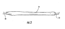
- FIG. 3 is a schematic view showing a heat dissipative structure applied to portion of the fiber optic assembly of FIG. 2 ;
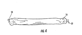
- FIG. 4 is a schematic view showing a heat resistant structure applied to portion of the fiber optic assembly of FIG. 3 ;
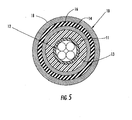
- FIG. 5 is a generic cross-sectional view of an explanatory fiber optic assembly
- FIG. 6 is another embodiment of a demarcation according to the disclosure.
- FIG. 1 The figures that are about to be described in detail show exemplary flame resistant coverings or structures for a transition location. These coverings generally include various layers and materials combined to provide flame or burn-through resistance more effectively than, for instance, a stand-alone, flame-resistant heat shrink employed over a spliced area of an enclosure.
- the components and materials of the composite flame resistant coverings are simple and economical to manufacture and use. Other advantages of the flame resistant coverings will be apparent from the following description and the attached drawings or can be learned through practice of the embodiments and their equivalents.
- FIG. 1 depicts a partial cutaway view of a fiber optic cable assembly 100 having a covering 10 disposed about a transition location TL.
- transition location TL is a location on the fiber optic assembly where a portion of a cable jacket or other outer coating of the fiber optic assembly has been removed and requires protection thereover and/or a preconnectorized assembly is attached.
- FIG. 1 depicts transition location TL between a preconnectorized assembly 50 and an end portion of fiber optic cable 22, thereby making a plug and play assembly.
- Preconnectorized assembly 50 includes a pigtail (not numbered) with a hardened connector (not shown) suitable for outdoor use as known in the art.
- fiber optic cable 22 may have any suitable design and/or construction.
- preconnectorized assembly 50 and fiber optic cable 22 have the desired flame-inhibiting characteristics; however, the structure used for closing/covering transition location TL is inherently flammable.
- Covering 10 is advantageous since it provides the transition location TL with the suitable characteristics so that fiber optic assembly 100 passes flame-retardant ratings such as UL 746C or the like, thereby qualifying the assembly for indoor or indoor/outdoor applications.
- transition locations TL include demarcation locations such as where optical fibers are spliced together such as attaching one or more preconnectorized assemblies, tap locations where optical fibers are extracted from a distribution cable, where fiber optic cables are opened and/or optical fibers are secured to inhibit the migration of excess fiber length along the assembly, and the like.
- covering 10 has a multi-layer construction. Covering 10 generally includes a heat dissipative structure 14 and a heat resistant structure 16.
- Heat dissipative structure 14 is disposed about a portion of transition location TL and acts as a heat shield, whereas heat resistant structure 16 is disposed about a portion of heat dissipative structure 14.
- An optional flame-retardant wrap 18 such as a heat shrink tubing or wrap may be placed about a portion of the heat resistant structure 16.
- covering 10 can be a composite structure or formed from individual components.
- a high temperature capable substrate such as mica
- an underlying heat dissipative structure such as metal foil
- flame-retardant wrap 18 is optionally used as part of covering 10 for sealing and/or mechanical protection and for some flame protection, heat shrink alone generally is also insufficient to provide the desired characteristics.
- covering 10 provides superior flame-resistance/performance.
- covering 10 is suitable for use over structure that is inherently flammable, thereby providing the desired characteristics for the portion having the underlying flammable structure.
- transition location TL may include an overmold portion that is inherently flammable, but after covering 10 is applied the transition location TL has the desired characteristics.
- Heat dissipative structure 14 can be any suitable material, but preferably has a metallic content for effective transfer of the thermal energy.
- heat dissipative structure 14 is formed from a metal foil such as aluminum.
- the thickness of heat dissipative structure 14 may depend on the material used, but one embodiment has a heat dissipative structure 14 with a thickness between about 0.02 millimeters and about 0.2 millimeters, but other thicknesses are possible.
- a material such as aluminum acts as a heat shield because of its thermal conduction properties that reduce localized heating.
- a typical aluminum foil has a thickness greater than about 0.02 millimeters such as between about 0.025 millimeters and 0.075 millimeters.
- materials other than aluminum may be utilized for heat dissipative structure 14 depending on specific requirements and/or regulations. For instance, relatively thin steel, copper, stainless steel or other metallic tapes wrapped longitudinally or tangentially may be used.
- Heat resistant structure 16 is disposed about a portion of heat dissipative structure 14 .
- Heat resistant structure 16 can withstand temperatures of up to about 1000 degrees C.
- heat resistant structure 16 may be mica material such as a mica tape.
- a suitable heat resistant mica tape is available from Coebgi, Inc. of Dover NH.
- heat resistant structure 16 may includes a polyurethane/polyphosphazene blends or aramid yarns and is not limited to mica.
- covering 10 may have any suitable construction and/or method for applying the same about the transition location TL.
- covering 10 may be provided in separate layers such as a metal foil that is formable about a portion of transition location TL and a mica tape.
- aluminum foil readily takes the desired set and seals about the transition location without much difficulty.
- the mica tape does not form like the aluminum foil so it may optionally include an adhesive layer or have other means such as applying an adhesive to the structure for forming and/or retaining about transition location TL if necessary.
- Adhesive layer can be applied to one of the components with any suitable method such as spray, brush, etc. However, it is noted that the adhesive, glue, or the like may be flammable and it should be used sparingly.
- covering 10 is a composite structure so that the layers may be applied about the transition location TL together.
- covering 10 may include a further outer layer for sealing and/or mechanical protection
- flame-retardant wrap 18 generally surrounds the transition location TL.
- Flame-retardant wrap 18 may be manufactured from any suitable material such as flame retardant polyolefin, fluoropolymer (such as fluorinated ethylene propylene (FEP) or PTFE), PVC, neoprene, or silicone elastomer.
- Flame-retardant wrap 18 may also be a heat shrink material that includes polyolefin heat shrink or ATUM flame retardant heat shrink tubing such as available from Raychem of Menlo Park, California, or FEP heat shrinks or Teflon® heat shrink tubing from Zeus Industrial Products, Inc. of Orangeburg, South Carolina.
- suitable heat shrink materials are not limited to the foregoing sources and examples.
- FIGS. 2-4 depict an exemplary method of making fiber optic assembly 100.
- FIG. 2 schematically depicts preconnectorized assembly 50 having one or more optical fibers 12' spliced to respective optical fibers 12 of fiber optic cable 22 at splice 24.
- the transition location TL must be closed and/or resealed while still meeting the necessary flame or smoke rating for the desired space.
- the concepts disclosed are advantageous since they allow a quick and easy method of reliably and ruggedly closing the transition location TL while still meeting the desired flame, smoke, mechanical, and optical ratings.
- fiber optic assembly 100 may be required to meet riser or plenum ratings for indoor applications or other suitable ratings for use in other applications.
- FIG. 3 and FIG. 4 depict heat dissipative structure 14 and heat resistant structure 16 applied as separate components they may have a composite structure (i.e., the structures are attached together and can be applied together as described above).
- FIG. 3 is a schematic view showing a heat dissipative structure 14 about a portion of transition location TL.
- one or more pieces of metal foil such as aluminum are applied to portion of the transition location TL. Since the metal foil is thin it is relatively easy to plastically deform the same to shape and close the same about the transition location TL.
- Other methods could use a glue or adhesive to secure the same, but this is not necessary with a thin metal foil.
- glue or adhesive may burn or cause smoke, which is a generally undesired effect.
- FIG. 4 is schematic view showing heat resistant structure 16 applied to portion of transition location TL about a portion of heat dissipative structure 14.
- Heat resistant structure 16 preferably can withstand relatively high temperatures such as up to about 1200 degrees C.
- heat resistant structure 16 is applied over heat dissipative structure 14 so that it generally covers the same.
- FIG. 5 it depicts a generic cross-sectional view of a fiber optic assembly showing the structure of covering 10.
- a typical structure within covering 10 is depicted for the purposes of illustration.
- optical fibers 12 are disposed within a protective tube 11 that has an overmold 13 disposed thereabout, thereby forming a structure at the transition location TL that is inherently flammable.
- covering 10 is provided over this inherently flammable structure so that the fiber optic assembly has the desired characteristics for the intended space.
- heat dissipative structure 14 and heat resistant structure 16 are disposed over the inherently flammable structure.
- optional heat shrink wrap 18 is applied for sealing and/or mechanical protection as depicted in FIG. 1 , thereby completing fiber optic assembly 100.
- FIG. 6 shows a fiber optic cable 122 having optical fibers 112 spliced at a splice area 124 to another suitable fiber optic structure.
- a flame resistant structure 110 which includes multiple layers such as a heat dissipative structure 114, a heat resistant structure 116 and a flame-retardant wrap 118, is slipped onto, wrapped, or otherwise placed over the transition location TL to complete the fiber optic assembly as discussed above.
- covering 110 is shaped as a tube or a sleeve that may include a slit or opening 128 to position the covering 110 over the transition location TL.
- the covering 110 may be a wrap that may be wrapped onto transition location TL.
- covering 110 provides necessary burn-through protection by using flame retardant particles or pieces 130 that may trapped between, for instance, the flame-retardant wrap 118 and the underlying structure of the fiber optic assembly.
- the pieces 130 are combinations of mica and aluminum schematically represented as square shapes but may present a honeycomb pattern or have a variety of other geometric forms, the size and distribution of which are such that upon heating, the particles 130 converge or are brought in close proximity to each other to produce a generally solid layer 132 as covering shrinks about the structure.
- strips of metal foil having mica particles can be attached to an inner surface of a flame-retardant wrap or heat shrink tubing.
- mica is suitable as a heat shield and the aluminum (or other suitable material) adds shielding and conduction to minimize localized heating, but, as noted above, other flame resistant and conductive materials may used in the alternative, or in addition to mica and aluminum.
Landscapes
- Physics & Mathematics (AREA)
- General Physics & Mathematics (AREA)
- Optics & Photonics (AREA)
- Engineering & Computer Science (AREA)
- Plasma & Fusion (AREA)
- Details Of Indoor Wiring (AREA)
- Insulated Conductors (AREA)
- Light Guides In General And Applications Therefor (AREA)
- Mechanical Coupling Of Light Guides (AREA)
Abstract
Description
- The disclosure is directed to flame-retardant fiber optic assemblies. More specifically, the disclosure is directed to fiber optic assemblies having transition locations that are flame-retardant for indoor or indoor/outdoor use.
- Fiber optic cables developed for indoor or indoor/outdoor use are required to meet stringent flame and/or smoke ratings, which are tested by independent laboratories. Typically, indoor or indoor/outdoor fiber optic cables are preconnectorized at respective ends with conventional fiber optic connectors and these assemblies meet the desired ratings for the space without modification. As optical fiber moves toward the subscriber and private networks become more advanced, there is a need for more robust and ruggedized fiber optic assemblies to interface with the emerging plug and play networks deployed for indoor and indoor/outdoor applications.
- Meeting this emerging demand can be very challenging since the fiber optic assemblies must meet the flame and/or smoke ratings along with still meeting the desired mechanical and optical performance characteristics. One skilled in the art realizes that the flame and/or smoke ratings can be difficult to pass since they generally involve an open flame and require all combustion to cease shortly after removal of the flame. Conversion of outdoor products to nonflammable assemblies by material substitution can be difficult due to the mechanical and environmental requirements that the assemblies must pass. Still further even minor variations in material composition may result in unwanted side effects, and complete material substitutions may exacerbate these unwanted effects. Moreover, designing and testing of the fiber optic assemblies is expensive and time consuming. The fiber optic industry requires a simple, reliable, and effective way to make fiber optic assemblies suitable for indoor and indoor/outdoor applications without extensive redesign and testing of the same.
- The disclosure is directed to various embodiments and methods for fiber optic assemblies having a covering that is flame-retardant for use at a transition location or the like. The covering has multiple components and provides the necessary characteristics to pass bum testing, thereby allowing indoor and/or indoor/outdoor use. The covering includes a heat dissipative structure and a heat resistant structure disposed about a transition location of the fiber optic assembly. Additionally, the covering may include an optional flame-retardant wrap configured for sealing and/or securing the covering such as a flame-retardant heat-shrink material. By way of example, the heat dissipative structure is a foil, such as an aluminum foil and the heat resistant structure is made of mica, but other materials are possible. The covering can have many suitable constructions for application such as individual components applied sequentially or a composite structure such as a wrap or tube for application together. Thus, the fiber optic assemblies are easy to manufacture and reliable.
- It is to be understood that both the foregoing general description and the following detailed description present embodiments, and are intended to provide an overview or framework for understanding the nature and character of the disclosure as it is claimed. The accompanying drawings are included to provide further understanding, and are incorporated into and constitute a part of this specification. The drawings illustrate the various example embodiments and, together with the description, serve to explain the principals and operations of the disclosure.
-
FIG. 1 is a partial cutaway view of a fiber optic assembly according to one embodiment; -
FIG. 2 is a schematic view showing the completed splicing of a preconnectorized assembly with a fiber optic cable to form the fiber optic assembly ofFIG. 1 ; -
FIG. 3 is a schematic view showing a heat dissipative structure applied to portion of the fiber optic assembly ofFIG. 2 ; -
FIG. 4 is a schematic view showing a heat resistant structure applied to portion of the fiber optic assembly ofFIG. 3 ; -
FIG. 5 is a generic cross-sectional view of an explanatory fiber optic assembly; and -
FIG. 6 is another embodiment of a demarcation according to the disclosure. - Detailed reference will now be made to the drawings in which examples of the disclosure are shown. The detailed description uses numerical and letter designations to refer to features of the drawings. Like or similar designations in the drawings and description have been used to refer to like or similar parts where possible.
- The drawings and detailed description provide a full and written description of the examples, and of the manner and process of making and using these examples, so as to enable one skilled in the pertinent art to make and use them, as well as the best mode of carrying out the concepts disclosed. The examples set forth in the drawings and detailed description are provided by way of explanation only and are not meant as limitations. The disclosure thus includes any modifications and variations of the following examples as come within the scope of the appended claims and their equivalents.
- The figures that are about to be described in detail show exemplary flame resistant coverings or structures for a transition location. These coverings generally include various layers and materials combined to provide flame or burn-through resistance more effectively than, for instance, a stand-alone, flame-resistant heat shrink employed over a spliced area of an enclosure. The components and materials of the composite flame resistant coverings are simple and economical to manufacture and use. Other advantages of the flame resistant coverings will be apparent from the following description and the attached drawings or can be learned through practice of the embodiments and their equivalents.
-
FIG. 1 depicts a partial cutaway view of a fiberoptic cable assembly 100 having a covering 10 disposed about a transition location TL. As used herein, transition location TL is a location on the fiber optic assembly where a portion of a cable jacket or other outer coating of the fiber optic assembly has been removed and requires protection thereover and/or a preconnectorized assembly is attached. For instance,FIG. 1 depicts transition location TL between apreconnectorized assembly 50 and an end portion of fiberoptic cable 22, thereby making a plug and play assembly.Preconnectorized assembly 50 includes a pigtail (not numbered) with a hardened connector (not shown) suitable for outdoor use as known in the art. Examples of hardened connectors are Opti-Tap® and Opti-tip™ connectors available from Coming Cable Systems of Hickory, North Carolina, but other suitable hardened connectors and//or preconnectorized assemblies are possible. Further, fiberoptic cable 22 may have any suitable design and/or construction. By way of example, bothpreconnectorized assembly 50 and fiberoptic cable 22 have the desired flame-inhibiting characteristics; however, the structure used for closing/covering transition location TL is inherently flammable. - Covering 10 is advantageous since it provides the transition location TL with the suitable characteristics so that fiber
optic assembly 100 passes flame-retardant ratings such as UL 746C or the like, thereby qualifying the assembly for indoor or indoor/outdoor applications. Examples of transition locations TL include demarcation locations such as where optical fibers are spliced together such as attaching one or more preconnectorized assemblies, tap locations where optical fibers are extracted from a distribution cable, where fiber optic cables are opened and/or optical fibers are secured to inhibit the migration of excess fiber length along the assembly, and the like. In this embodiment, covering 10 has a multi-layer construction. Covering 10 generally includes a heatdissipative structure 14 and a heatresistant structure 16. Heatdissipative structure 14 is disposed about a portion of transition location TL and acts as a heat shield, whereas heatresistant structure 16 is disposed about a portion of heatdissipative structure 14. An optional flame-retardant wrap 18 such as a heat shrink tubing or wrap may be placed about a portion of the heatresistant structure 16. As discussed below, covering 10 can be a composite structure or formed from individual components. - The combination of a high temperature capable substrate, such as mica, along with an underlying heat dissipative structure, such as metal foil, provides the needed burn-through resistance that a single layer of either material is incapable of providing. Moreover, although flame-
retardant wrap 18 is optionally used as part of covering 10 for sealing and/or mechanical protection and for some flame protection, heat shrink alone generally is also insufficient to provide the desired characteristics. Thus, covering 10 provides superior flame-resistance/performance. Additionally, covering 10 is suitable for use over structure that is inherently flammable, thereby providing the desired characteristics for the portion having the underlying flammable structure. By way of example, transition location TL may include an overmold portion that is inherently flammable, but after covering 10 is applied the transition location TL has the desired characteristics. - Heat
dissipative structure 14 can be any suitable material, but preferably has a metallic content for effective transfer of the thermal energy. By way of example, heatdissipative structure 14 is formed from a metal foil such as aluminum. The thickness of heatdissipative structure 14 may depend on the material used, but one embodiment has a heatdissipative structure 14 with a thickness between about 0.02 millimeters and about 0.2 millimeters, but other thicknesses are possible. A material such as aluminum acts as a heat shield because of its thermal conduction properties that reduce localized heating.
A typical aluminum foil has a thickness greater than about 0.02 millimeters such as between about 0.025 millimeters and 0.075 millimeters. The skilled artisan will recognize that materials other than aluminum may be utilized forheat dissipative structure 14 depending on specific requirements and/or regulations. For instance, relatively thin steel, copper, stainless steel or other metallic tapes wrapped longitudinally or tangentially may be used. - Heat
resistant structure 16 is disposed about a portion ofheat dissipative structure 14. Heatresistant structure 16 can withstand temperatures of up to about 1000 degrees C. By way of example, heatresistant structure 16 may be mica material such as a mica tape. A suitable heat resistant mica tape is available from Coebgi, Inc. of Dover NH. Of course, other suitable heat resistant structures are possible. For instance, heatresistant structure 16 may includes a polyurethane/polyphosphazene blends or aramid yarns and is not limited to mica. - The multiple components of covering 10 may have any suitable construction and/or method for applying the same about the transition location TL. For instance, covering 10 may be provided in separate layers such as a metal foil that is formable about a portion of transition location TL and a mica tape. Generally speaking, aluminum foil readily takes the desired set and seals about the transition location without much difficulty. However, the mica tape does not form like the aluminum foil so it may optionally include an adhesive layer or have other means such as applying an adhesive to the structure for forming and/or retaining about transition location TL if necessary. Adhesive layer can be applied to one of the components with any suitable method such as spray, brush, etc. However, it is noted that the adhesive, glue, or the like may be flammable and it should be used sparingly. In other embodiments, covering 10 is a composite structure so that the layers may be applied about the transition location TL together. Moreover, covering 10 may include a further outer layer for sealing and/or mechanical protection
- As shown, flame-
retardant wrap 18 generally surrounds the transition location TL. Flame-retardant wrap 18 may be manufactured from any suitable material such as flame retardant polyolefin, fluoropolymer (such as fluorinated ethylene propylene (FEP) or PTFE), PVC, neoprene, or silicone elastomer. Flame-retardant wrap 18 may also be a heat shrink material that includes polyolefin heat shrink or ATUM flame retardant heat shrink tubing such as available from Raychem of Menlo Park, California, or FEP heat shrinks or Teflon® heat shrink tubing from Zeus Industrial Products, Inc. of Orangeburg, South Carolina. Of course, suitable heat shrink materials are not limited to the foregoing sources and examples. -
FIGS. 2-4 depict an exemplary method of makingfiber optic assembly 100.FIG. 2 schematically depictspreconnectorized assembly 50 having one or more optical fibers 12' spliced to respectiveoptical fibers 12 offiber optic cable 22 atsplice 24. Once the operations of splicing, excess fiber management, providing a splice protector or protective tube, strain relief of strength members, sealing, overmolding, etc. are completed, the transition location TL must be closed and/or resealed while still meeting the necessary flame or smoke rating for the desired space. The concepts disclosed are advantageous since they allow a quick and easy method of reliably and ruggedly closing the transition location TL while still meeting the desired flame, smoke, mechanical, and optical ratings. For instance,fiber optic assembly 100 may be required to meet riser or plenum ratings for indoor applications or other suitable ratings for use in other applications. - Although
FIG. 3 andFIG. 4 depictheat dissipative structure 14 and heatresistant structure 16 applied as separate components they may have a composite structure (i.e., the structures are attached together and can be applied together as described above). Specifically,FIG. 3 is a schematic view showing aheat dissipative structure 14 about a portion of transition location TL. For instance, one or more pieces of metal foil such as aluminum are applied to portion of the transition location TL. Since the metal foil is thin it is relatively easy to plastically deform the same to shape and close the same about the transition location TL. Other methods could use a glue or adhesive to secure the same, but this is not necessary with a thin metal foil. Moreover, the use of glue or adhesive may burn or cause smoke, which is a generally undesired effect. -
FIG. 4 is schematic view showing heatresistant structure 16 applied to portion of transition location TL about a portion ofheat dissipative structure 14. Heatresistant structure 16 preferably can withstand relatively high temperatures such as up to about 1200 degrees C. By way of example, heatresistant structure 16 is applied overheat dissipative structure 14 so that it generally covers the same. - Turning now to
FIG. 5 , it depicts a generic cross-sectional view of a fiber optic assembly showing the structure of covering 10. A typical structure within covering 10 is depicted for the purposes of illustration. As depicted,optical fibers 12 are disposed within aprotective tube 11 that has anovermold 13 disposed thereabout, thereby forming a structure at the transition location TL that is inherently flammable. Thus, covering 10 is provided over this inherently flammable structure so that the fiber optic assembly has the desired characteristics for the intended space. Specifically,heat dissipative structure 14 and heatresistant structure 16 are disposed over the inherently flammable structure. Finally, optional heat shrinkwrap 18 is applied for sealing and/or mechanical protection as depicted inFIG. 1 , thereby completing fiberoptic assembly 100. - With reference now to
FIG. 6 , another embodiment of a flameresistant covering 110. Specifically,FIG. 6 shows afiber optic cable 122 havingoptical fibers 112 spliced at asplice area 124 to another suitable fiber optic structure. A flameresistant structure 110, which includes multiple layers such as aheat dissipative structure 114, a heatresistant structure 116 and a flame-retardant wrap 118, is slipped onto, wrapped, or otherwise placed over the transition location TL to complete the fiber optic assembly as discussed above. In this example, covering 110 is shaped as a tube or a sleeve that may include a slit or opening 128 to position the covering 110 over the transition location TL. Alternatively, the covering 110 may be a wrap that may be wrapped onto transition location TL. - In any of its alternative forms, covering 110 provides necessary burn-through protection by using flame retardant particles or
pieces 130 that may trapped between, for instance, the flame-retardant wrap 118 and the underlying structure of the fiber optic assembly. In this example, thepieces 130 are combinations of mica and aluminum schematically represented as square shapes but may present a honeycomb pattern or have a variety of other geometric forms, the size and distribution of which are such that upon heating, theparticles 130 converge or are brought in close proximity to each other to produce a generallysolid layer 132 as covering shrinks about the structure. In other embodiments, strips of metal foil having mica particles can be attached to an inner surface of a flame-retardant wrap or heat shrink tubing. Again, mica is suitable as a heat shield and the aluminum (or other suitable material) adds shielding and conduction to minimize localized heating, but, as noted above, other flame resistant and conductive materials may used in the alternative, or in addition to mica and aluminum. - It will be apparent to those skilled in the art that various modifications and variations can be made without departing from the spirit and scope of the invention. Thus, it is intended that the disclosure cover the modifications and variations of this invention, provided they come within the scope of the appended claims and their equivalents.
Claims (15)
- A fiber optic assembly having a transition location with a covering, the covering comprising:a heat dissipative structure disposed about a portion of the transition location;a heat resistant structure disposed about a portion of the heat dissipative structure; anda flame-retardant wrap disposed about a portion of the heat resistant structure.
- The fiber optic assembly of Claim 1, wherein the heat dissipative structure is a metal foil.
- The fiber optic assembly of Claim 1, wherein the heat resistant structure includes mica.
- The fiber optic assembly of Claim 1, wherein the heat dissipative structure, the heat resistant structure and the flame-retardant wrap form a bonded wrap for application about the transition location.
- The fiber optic assembly of Claim 1, wherein the heat dissipative structure, the heat resistant structure and the shrink wrap are formed together in a tubular shape for application about the transition location.
- A fiber optic assembly having a transition location with a covering, the covering comprising:a metal foil disposed about a portion of the transition location;a mica material disposed about a portion of the metal foil; anda flame-retardant heat shrink disposed radially outward of a portion of the heat barrier and a portion of the flame barrier at the transition location.
- The fiber optic assembly of Claim 6, wherein the metal foil, the mica material and the flame-retardant heat shrink form a bonded wrap for application about the transition location.
- The fiber optic assembly of Claim 6, wherein the metal foil, the mica material and the flame-retardant heat shrink form are formed together in a tubular shape for application about the transition location.
- The fiber optic assembly of Claims 1 or 6, wherein the transition location is selected from the group of a demarcation location, a tap location, and a splice location.
- A method of forming a covering about a transition location of a fiber optic assembly, comprising the steps of:placing a heat dissipative structure around a portion of the transition location; andplacing a heat resistant structure about a portion of the heat dissipative structure.
- The method of Claim 10, further including the step of placing a flame-retardant wrap about a portion of the heat resistant structure.
- The method of Claim 11, wherein the heat dissipative structure, heat resistant structure, and flame-retardant wrap form a composite structure.
- The method of Claim 10, wherein the heat dissipative structure and heat resistant structure form a composite structure.
- The method of Claim 10, wherein the heat dissipative structure is a metal foil and the heat resistant structure includes mica.
- The method of Claim 14, further including placing a flame-retardant wrap about a portion of the heat resistant structure.
Applications Claiming Priority (1)
| Application Number | Priority Date | Filing Date | Title |
|---|---|---|---|
| US12/231,113 US20100054690A1 (en) | 2008-08-29 | 2008-08-29 | Flame-retardant fiber optic assemblies |
Publications (2)
| Publication Number | Publication Date |
|---|---|
| EP2159614A1 true EP2159614A1 (en) | 2010-03-03 |
| EP2159614B1 EP2159614B1 (en) | 2012-08-08 |
Family
ID=41463686
Family Applications (1)
| Application Number | Title | Priority Date | Filing Date |
|---|---|---|---|
| EP09010649A Not-in-force EP2159614B1 (en) | 2008-08-29 | 2009-08-19 | Flame-retardant fiber optic assembly |
Country Status (5)
| Country | Link |
|---|---|
| US (1) | US20100054690A1 (en) |
| EP (1) | EP2159614B1 (en) |
| AU (1) | AU2009208158B2 (en) |
| ES (1) | ES2391495T3 (en) |
| PT (1) | PT2159614E (en) |
Families Citing this family (1)
| Publication number | Priority date | Publication date | Assignee | Title |
|---|---|---|---|---|
| US9277684B2 (en) * | 2013-03-13 | 2016-03-01 | Federal-Mogul Powertrain, Inc. | Self-wrapping EMI shielding textile sleeve and method of construction thereof |
Citations (6)
| Publication number | Priority date | Publication date | Assignee | Title |
|---|---|---|---|---|
| US4472222A (en) * | 1980-02-08 | 1984-09-18 | N. V. Raychem S. A. | Recoverable closure assembly |
| GB2184512A (en) * | 1985-12-18 | 1987-06-24 | Eilentropp Hew Kabel | Fire resistant covering |
| JPH09140818A (en) * | 1995-11-27 | 1997-06-03 | Furukawa Techno Material:Kk | Fireproof cover for cable or cable pipe |
| EP1022596A2 (en) * | 1999-01-20 | 2000-07-26 | Telefonaktiebolaget L M Ericsson (Publ) | Heat-shrinkable tube for protection of optical fiber splices |
| US6400874B1 (en) * | 1999-05-04 | 2002-06-04 | Corning Cable Systems, Llc | Optical cable |
| EP1316830A2 (en) * | 2001-12-03 | 2003-06-04 | Alcatel | Dual-layer fire retardant cable structure with air gap |
Family Cites Families (16)
| Publication number | Priority date | Publication date | Assignee | Title |
|---|---|---|---|---|
| CA1197963A (en) * | 1981-07-22 | 1985-12-17 | Michito Matsumoto | Apparatus and method for heating heat-shrinkable tubes |
| US4511415A (en) * | 1983-02-28 | 1985-04-16 | Thomas & Betts Corporation | Method of sealing an electrical cable |
| JPS63200105A (en) * | 1987-02-16 | 1988-08-18 | Mitsubishi Cable Ind Ltd | Structure body for optical fiber cable branch part |
| US4969705A (en) * | 1990-01-19 | 1990-11-13 | Kingston Technologies, L.P. | Memory polymer multiple cavity fiber splicer |
| US5173960A (en) * | 1992-03-06 | 1992-12-22 | At&T Bell Laboratories | Cable having superior resistance to flame spread and smoke evolution |
| US6049647A (en) * | 1997-09-16 | 2000-04-11 | Siecor Operations, Llc | Composite fiber optic cable |
| DE19811772A1 (en) * | 1998-03-18 | 1999-09-23 | Cit Alcatel | Flame retardant optical cable |
| US6099170A (en) * | 1999-01-07 | 2000-08-08 | Thomas & Betters International, Inc. | Splice protection sleeve for a plurality of optical fibers and method of installation |
| DE60120119D1 (en) * | 2000-03-07 | 2006-07-06 | Tyco Electronics Raychem Nv | CABLE SEAL |
| WO2002057828A2 (en) * | 2001-01-16 | 2002-07-25 | Parker Hannifin Corporation | Flame retardant tubing for a bundle |
| US7155093B2 (en) * | 2004-05-24 | 2006-12-26 | Corning Cable Systems Llc | Distribution cable having overmolded mid-span access location with preferential bending |
| US7139456B2 (en) * | 2004-10-27 | 2006-11-21 | Tomoegawa Paper Co., Ltd. | Optical fiber wiring sheet and method of manufacturing same |
| US7277614B2 (en) * | 2004-12-03 | 2007-10-02 | Corning Cable Systems Llc | Tether assembly having individual connector ports |
| US7444056B2 (en) * | 2005-05-31 | 2008-10-28 | Tyco Electronics Corporation | Optical network architecture and terminals for use in such networks |
| US20080170828A1 (en) * | 2007-01-12 | 2008-07-17 | Robert Bruce Elkins | Indoor cable assemblies with flexible network access point |
| US20080187276A1 (en) * | 2007-02-02 | 2008-08-07 | Reginald Roberts | Flexible optical fiber tape and distribution cable assembly using same |
-
2008
- 2008-08-29 US US12/231,113 patent/US20100054690A1/en not_active Abandoned
-
2009
- 2009-08-14 AU AU2009208158A patent/AU2009208158B2/en not_active Ceased
- 2009-08-19 EP EP09010649A patent/EP2159614B1/en not_active Not-in-force
- 2009-08-19 ES ES09010649T patent/ES2391495T3/en active Active
- 2009-08-19 PT PT09010649T patent/PT2159614E/en unknown
Patent Citations (6)
| Publication number | Priority date | Publication date | Assignee | Title |
|---|---|---|---|---|
| US4472222A (en) * | 1980-02-08 | 1984-09-18 | N. V. Raychem S. A. | Recoverable closure assembly |
| GB2184512A (en) * | 1985-12-18 | 1987-06-24 | Eilentropp Hew Kabel | Fire resistant covering |
| JPH09140818A (en) * | 1995-11-27 | 1997-06-03 | Furukawa Techno Material:Kk | Fireproof cover for cable or cable pipe |
| EP1022596A2 (en) * | 1999-01-20 | 2000-07-26 | Telefonaktiebolaget L M Ericsson (Publ) | Heat-shrinkable tube for protection of optical fiber splices |
| US6400874B1 (en) * | 1999-05-04 | 2002-06-04 | Corning Cable Systems, Llc | Optical cable |
| EP1316830A2 (en) * | 2001-12-03 | 2003-06-04 | Alcatel | Dual-layer fire retardant cable structure with air gap |
Also Published As
| Publication number | Publication date |
|---|---|
| AU2009208158A8 (en) | 2012-04-26 |
| EP2159614B1 (en) | 2012-08-08 |
| US20100054690A1 (en) | 2010-03-04 |
| AU2009208158A1 (en) | 2010-03-18 |
| PT2159614E (en) | 2012-10-18 |
| AU2009208158B2 (en) | 2012-05-31 |
| ES2391495T3 (en) | 2012-11-27 |
Similar Documents
| Publication | Publication Date | Title |
|---|---|---|
| US11841542B2 (en) | Pre-terminated optical fibre cable assembly, methods of manufacture and installation thereof | |
| RU2406172C2 (en) | Shielded cable assembly for aviation engine | |
| US7848604B2 (en) | Fiber-optic cable and method of manufacture | |
| MX2007013908A (en) | High strength-to-weight-ratio slickline and multiline cables. | |
| WO2017027283A1 (en) | Optical fiber cable | |
| US11249252B2 (en) | Flexible splice protector | |
| US11579393B2 (en) | Fiber optic cable breakout assembly | |
| US9846289B2 (en) | Method for manufacturing a cable component | |
| US20150160415A1 (en) | Flexible, Low Profile Kink Resistant Fiber Optic Splice Tension Sleeve | |
| SE1400140A1 (en) | Power cable and method of manufacturing the same | |
| WO2014160787A1 (en) | High pressure splice housing | |
| FR3015105A1 (en) | ||
| EP2159614B1 (en) | Flame-retardant fiber optic assembly | |
| DE3878791T2 (en) | FIBER OPTICAL CABLE FOR HIGH TEMPERATURE APPLICATION. | |
| KR20200052825A (en) | Jointing System Of Power Cable | |
| GB2079485A (en) | Armoured wire splices | |
| KR20200101857A (en) | Jointing Structure Of Power Cable | |
| DE102016207323A1 (en) | Electrical line | |
| CA2549538A1 (en) | Tactical flexible fibre optic splice enclosure and method of installation | |
| CN216436779U (en) | Cable connection joint | |
| EP3089298B1 (en) | Reinforcement arrangement for submarine cable junctions | |
| JP2005137176A (en) | Cable connection protector | |
| CN210074743U (en) | High-voltage cable waterproof joint | |
| JP5619557B2 (en) | Heat-shrinkable tube and power cable connection using the same | |
| Bayer et al. | Wire and cable update, 1991 |
Legal Events
| Date | Code | Title | Description |
|---|---|---|---|
| PUAI | Public reference made under article 153(3) epc to a published international application that has entered the european phase |
Free format text: ORIGINAL CODE: 0009012 |
|
| AK | Designated contracting states |
Kind code of ref document: A1 Designated state(s): AT BE BG CH CY CZ DE DK EE ES FI FR GB GR HR HU IE IS IT LI LT LU LV MC MK MT NL NO PL PT RO SE SI SK SM TR |
|
| AX | Request for extension of the european patent |
Extension state: AL BA RS |
|
| 17P | Request for examination filed |
Effective date: 20100817 |
|
| 17Q | First examination report despatched |
Effective date: 20101022 |
|
| GRAP | Despatch of communication of intention to grant a patent |
Free format text: ORIGINAL CODE: EPIDOSNIGR1 |
|
| GRAS | Grant fee paid |
Free format text: ORIGINAL CODE: EPIDOSNIGR3 |
|
| GRAA | (expected) grant |
Free format text: ORIGINAL CODE: 0009210 |
|
| AK | Designated contracting states |
Kind code of ref document: B1 Designated state(s): AT BE BG CH CY CZ DE DK EE ES FI FR GB GR HR HU IE IS IT LI LT LU LV MC MK MT NL NO PL PT RO SE SI SK SM TR |
|
| REG | Reference to a national code |
Ref country code: GB Ref legal event code: FG4D |
|
| REG | Reference to a national code |
Ref country code: AT Ref legal event code: REF Ref document number: 570059 Country of ref document: AT Kind code of ref document: T Effective date: 20120815 Ref country code: CH Ref legal event code: EP |
|
| REG | Reference to a national code |
Ref country code: IE Ref legal event code: FG4D |
|
| REG | Reference to a national code |
Ref country code: DE Ref legal event code: R096 Ref document number: 602009008736 Country of ref document: DE Effective date: 20121004 |
|
| REG | Reference to a national code |
Ref country code: PT Ref legal event code: SC4A Free format text: AVAILABILITY OF NATIONAL TRANSLATION Effective date: 20121010 |
|
| REG | Reference to a national code |
Ref country code: ES Ref legal event code: FG2A Ref document number: 2391495 Country of ref document: ES Kind code of ref document: T3 Effective date: 20121127 |
|
| REG | Reference to a national code |
Ref country code: NL Ref legal event code: VDEP Effective date: 20120808 |
|
| REG | Reference to a national code |
Ref country code: AT Ref legal event code: MK05 Ref document number: 570059 Country of ref document: AT Kind code of ref document: T Effective date: 20120808 |
|
| REG | Reference to a national code |
Ref country code: LT Ref legal event code: MG4D Effective date: 20120808 |
|
| PG25 | Lapsed in a contracting state [announced via postgrant information from national office to epo] |
Ref country code: HR Free format text: LAPSE BECAUSE OF FAILURE TO SUBMIT A TRANSLATION OF THE DESCRIPTION OR TO PAY THE FEE WITHIN THE PRESCRIBED TIME-LIMIT Effective date: 20120808 Ref country code: LT Free format text: LAPSE BECAUSE OF FAILURE TO SUBMIT A TRANSLATION OF THE DESCRIPTION OR TO PAY THE FEE WITHIN THE PRESCRIBED TIME-LIMIT Effective date: 20120808 Ref country code: AT Free format text: LAPSE BECAUSE OF FAILURE TO SUBMIT A TRANSLATION OF THE DESCRIPTION OR TO PAY THE FEE WITHIN THE PRESCRIBED TIME-LIMIT Effective date: 20120808 Ref country code: FI Free format text: LAPSE BECAUSE OF FAILURE TO SUBMIT A TRANSLATION OF THE DESCRIPTION OR TO PAY THE FEE WITHIN THE PRESCRIBED TIME-LIMIT Effective date: 20120808 Ref country code: CY Free format text: LAPSE BECAUSE OF FAILURE TO SUBMIT A TRANSLATION OF THE DESCRIPTION OR TO PAY THE FEE WITHIN THE PRESCRIBED TIME-LIMIT Effective date: 20120808 Ref country code: IS Free format text: LAPSE BECAUSE OF FAILURE TO SUBMIT A TRANSLATION OF THE DESCRIPTION OR TO PAY THE FEE WITHIN THE PRESCRIBED TIME-LIMIT Effective date: 20121208 Ref country code: NO Free format text: LAPSE BECAUSE OF FAILURE TO SUBMIT A TRANSLATION OF THE DESCRIPTION OR TO PAY THE FEE WITHIN THE PRESCRIBED TIME-LIMIT Effective date: 20121108 |
|
| PG25 | Lapsed in a contracting state [announced via postgrant information from national office to epo] |
Ref country code: LV Free format text: LAPSE BECAUSE OF FAILURE TO SUBMIT A TRANSLATION OF THE DESCRIPTION OR TO PAY THE FEE WITHIN THE PRESCRIBED TIME-LIMIT Effective date: 20120808 Ref country code: SI Free format text: LAPSE BECAUSE OF FAILURE TO SUBMIT A TRANSLATION OF THE DESCRIPTION OR TO PAY THE FEE WITHIN THE PRESCRIBED TIME-LIMIT Effective date: 20120808 Ref country code: PL Free format text: LAPSE BECAUSE OF FAILURE TO SUBMIT A TRANSLATION OF THE DESCRIPTION OR TO PAY THE FEE WITHIN THE PRESCRIBED TIME-LIMIT Effective date: 20120808 Ref country code: GR Free format text: LAPSE BECAUSE OF FAILURE TO SUBMIT A TRANSLATION OF THE DESCRIPTION OR TO PAY THE FEE WITHIN THE PRESCRIBED TIME-LIMIT Effective date: 20121109 Ref country code: SE Free format text: LAPSE BECAUSE OF FAILURE TO SUBMIT A TRANSLATION OF THE DESCRIPTION OR TO PAY THE FEE WITHIN THE PRESCRIBED TIME-LIMIT Effective date: 20120808 Ref country code: BE Free format text: LAPSE BECAUSE OF FAILURE TO SUBMIT A TRANSLATION OF THE DESCRIPTION OR TO PAY THE FEE WITHIN THE PRESCRIBED TIME-LIMIT Effective date: 20120808 |
|
| PGFP | Annual fee paid to national office [announced via postgrant information from national office to epo] |
Ref country code: PT Payment date: 20121116 Year of fee payment: 4 Ref country code: IT Payment date: 20120831 Year of fee payment: 4 |
|
| PG25 | Lapsed in a contracting state [announced via postgrant information from national office to epo] |
Ref country code: NL Free format text: LAPSE BECAUSE OF FAILURE TO SUBMIT A TRANSLATION OF THE DESCRIPTION OR TO PAY THE FEE WITHIN THE PRESCRIBED TIME-LIMIT Effective date: 20120808 Ref country code: MC Free format text: LAPSE BECAUSE OF NON-PAYMENT OF DUE FEES Effective date: 20120831 |
|
| PG25 | Lapsed in a contracting state [announced via postgrant information from national office to epo] |
Ref country code: CZ Free format text: LAPSE BECAUSE OF FAILURE TO SUBMIT A TRANSLATION OF THE DESCRIPTION OR TO PAY THE FEE WITHIN THE PRESCRIBED TIME-LIMIT Effective date: 20120808 Ref country code: DK Free format text: LAPSE BECAUSE OF FAILURE TO SUBMIT A TRANSLATION OF THE DESCRIPTION OR TO PAY THE FEE WITHIN THE PRESCRIBED TIME-LIMIT Effective date: 20120808 Ref country code: RO Free format text: LAPSE BECAUSE OF FAILURE TO SUBMIT A TRANSLATION OF THE DESCRIPTION OR TO PAY THE FEE WITHIN THE PRESCRIBED TIME-LIMIT Effective date: 20120808 Ref country code: EE Free format text: LAPSE BECAUSE OF FAILURE TO SUBMIT A TRANSLATION OF THE DESCRIPTION OR TO PAY THE FEE WITHIN THE PRESCRIBED TIME-LIMIT Effective date: 20120808 |
|
| REG | Reference to a national code |
Ref country code: IE Ref legal event code: MM4A |
|
| PG25 | Lapsed in a contracting state [announced via postgrant information from national office to epo] |
Ref country code: SK Free format text: LAPSE BECAUSE OF FAILURE TO SUBMIT A TRANSLATION OF THE DESCRIPTION OR TO PAY THE FEE WITHIN THE PRESCRIBED TIME-LIMIT Effective date: 20120808 |
|
| PLBE | No opposition filed within time limit |
Free format text: ORIGINAL CODE: 0009261 |
|
| STAA | Information on the status of an ep patent application or granted ep patent |
Free format text: STATUS: NO OPPOSITION FILED WITHIN TIME LIMIT |
|
| 26N | No opposition filed |
Effective date: 20130510 |
|
| PG25 | Lapsed in a contracting state [announced via postgrant information from national office to epo] |
Ref country code: IE Free format text: LAPSE BECAUSE OF NON-PAYMENT OF DUE FEES Effective date: 20120819 Ref country code: BG Free format text: LAPSE BECAUSE OF FAILURE TO SUBMIT A TRANSLATION OF THE DESCRIPTION OR TO PAY THE FEE WITHIN THE PRESCRIBED TIME-LIMIT Effective date: 20121108 |
|
| REG | Reference to a national code |
Ref country code: DE Ref legal event code: R097 Ref document number: 602009008736 Country of ref document: DE Effective date: 20130510 |
|
| PG25 | Lapsed in a contracting state [announced via postgrant information from national office to epo] |
Ref country code: MT Free format text: LAPSE BECAUSE OF FAILURE TO SUBMIT A TRANSLATION OF THE DESCRIPTION OR TO PAY THE FEE WITHIN THE PRESCRIBED TIME-LIMIT Effective date: 20120808 |
|
| PGFP | Annual fee paid to national office [announced via postgrant information from national office to epo] |
Ref country code: GB Payment date: 20130827 Year of fee payment: 5 Ref country code: FR Payment date: 20130819 Year of fee payment: 5 |
|
| REG | Reference to a national code |
Ref country code: CH Ref legal event code: PL |
|
| PG25 | Lapsed in a contracting state [announced via postgrant information from national office to epo] |
Ref country code: CH Free format text: LAPSE BECAUSE OF NON-PAYMENT OF DUE FEES Effective date: 20130831 Ref country code: LI Free format text: LAPSE BECAUSE OF NON-PAYMENT OF DUE FEES Effective date: 20130831 Ref country code: TR Free format text: LAPSE BECAUSE OF FAILURE TO SUBMIT A TRANSLATION OF THE DESCRIPTION OR TO PAY THE FEE WITHIN THE PRESCRIBED TIME-LIMIT Effective date: 20120808 |
|
| REG | Reference to a national code |
Ref country code: PT Ref legal event code: MM4A Free format text: LAPSE DUE TO NON-PAYMENT OF FEES Effective date: 20140519 |
|
| PG25 | Lapsed in a contracting state [announced via postgrant information from national office to epo] |
Ref country code: LU Free format text: LAPSE BECAUSE OF NON-PAYMENT OF DUE FEES Effective date: 20120819 Ref country code: SM Free format text: LAPSE BECAUSE OF FAILURE TO SUBMIT A TRANSLATION OF THE DESCRIPTION OR TO PAY THE FEE WITHIN THE PRESCRIBED TIME-LIMIT Effective date: 20120808 Ref country code: IT Free format text: LAPSE BECAUSE OF NON-PAYMENT OF DUE FEES Effective date: 20130819 |
|
| PG25 | Lapsed in a contracting state [announced via postgrant information from national office to epo] |
Ref country code: HU Free format text: LAPSE BECAUSE OF FAILURE TO SUBMIT A TRANSLATION OF THE DESCRIPTION OR TO PAY THE FEE WITHIN THE PRESCRIBED TIME-LIMIT Effective date: 20090819 |
|
| PG25 | Lapsed in a contracting state [announced via postgrant information from national office to epo] |
Ref country code: PT Free format text: LAPSE BECAUSE OF NON-PAYMENT OF DUE FEES Effective date: 20140519 |
|
| GBPC | Gb: european patent ceased through non-payment of renewal fee |
Effective date: 20140819 |
|
| REG | Reference to a national code |
Ref country code: FR Ref legal event code: ST Effective date: 20150430 |
|
| PG25 | Lapsed in a contracting state [announced via postgrant information from national office to epo] |
Ref country code: MK Free format text: LAPSE BECAUSE OF FAILURE TO SUBMIT A TRANSLATION OF THE DESCRIPTION OR TO PAY THE FEE WITHIN THE PRESCRIBED TIME-LIMIT Effective date: 20120808 Ref country code: GB Free format text: LAPSE BECAUSE OF NON-PAYMENT OF DUE FEES Effective date: 20140819 |
|
| PG25 | Lapsed in a contracting state [announced via postgrant information from national office to epo] |
Ref country code: FR Free format text: LAPSE BECAUSE OF NON-PAYMENT OF DUE FEES Effective date: 20140901 |
|
| PGFP | Annual fee paid to national office [announced via postgrant information from national office to epo] |
Ref country code: ES Payment date: 20190902 Year of fee payment: 11 Ref country code: DE Payment date: 20190715 Year of fee payment: 11 |
|
| REG | Reference to a national code |
Ref country code: DE Ref legal event code: R119 Ref document number: 602009008736 Country of ref document: DE |
|
| PG25 | Lapsed in a contracting state [announced via postgrant information from national office to epo] |
Ref country code: DE Free format text: LAPSE BECAUSE OF NON-PAYMENT OF DUE FEES Effective date: 20210302 |
|
| REG | Reference to a national code |
Ref country code: ES Ref legal event code: FD2A Effective date: 20220110 |
|
| PG25 | Lapsed in a contracting state [announced via postgrant information from national office to epo] |
Ref country code: ES Free format text: LAPSE BECAUSE OF NON-PAYMENT OF DUE FEES Effective date: 20200820 |