EP2159415A2 - Method and apparatus for controlling the yaw angle of a wind turbine - Google Patents
Method and apparatus for controlling the yaw angle of a wind turbine Download PDFInfo
- Publication number
- EP2159415A2 EP2159415A2 EP09167788A EP09167788A EP2159415A2 EP 2159415 A2 EP2159415 A2 EP 2159415A2 EP 09167788 A EP09167788 A EP 09167788A EP 09167788 A EP09167788 A EP 09167788A EP 2159415 A2 EP2159415 A2 EP 2159415A2
- Authority
- EP
- European Patent Office
- Prior art keywords
- yaw
- yaw angle
- angle
- wind turbine
- wind direction
- Prior art date
- Legal status (The legal status is an assumption and is not a legal conclusion. Google has not performed a legal analysis and makes no representation as to the accuracy of the status listed.)
- Granted
Links
Images




Classifications
-
- F—MECHANICAL ENGINEERING; LIGHTING; HEATING; WEAPONS; BLASTING
- F03—MACHINES OR ENGINES FOR LIQUIDS; WIND, SPRING, OR WEIGHT MOTORS; PRODUCING MECHANICAL POWER OR A REACTIVE PROPULSIVE THRUST, NOT OTHERWISE PROVIDED FOR
- F03D—WIND MOTORS
- F03D7/00—Controlling wind motors
- F03D7/02—Controlling wind motors the wind motors having rotation axis substantially parallel to the air flow entering the rotor
- F03D7/04—Automatic control; Regulation
- F03D7/042—Automatic control; Regulation by means of an electrical or electronic controller
- F03D7/043—Automatic control; Regulation by means of an electrical or electronic controller characterised by the type of control logic
-
- F—MECHANICAL ENGINEERING; LIGHTING; HEATING; WEAPONS; BLASTING
- F03—MACHINES OR ENGINES FOR LIQUIDS; WIND, SPRING, OR WEIGHT MOTORS; PRODUCING MECHANICAL POWER OR A REACTIVE PROPULSIVE THRUST, NOT OTHERWISE PROVIDED FOR
- F03D—WIND MOTORS
- F03D7/00—Controlling wind motors
- F03D7/02—Controlling wind motors the wind motors having rotation axis substantially parallel to the air flow entering the rotor
- F03D7/0204—Controlling wind motors the wind motors having rotation axis substantially parallel to the air flow entering the rotor for orientation in relation to wind direction
-
- F—MECHANICAL ENGINEERING; LIGHTING; HEATING; WEAPONS; BLASTING
- F03—MACHINES OR ENGINES FOR LIQUIDS; WIND, SPRING, OR WEIGHT MOTORS; PRODUCING MECHANICAL POWER OR A REACTIVE PROPULSIVE THRUST, NOT OTHERWISE PROVIDED FOR
- F03D—WIND MOTORS
- F03D7/00—Controlling wind motors
- F03D7/02—Controlling wind motors the wind motors having rotation axis substantially parallel to the air flow entering the rotor
- F03D7/022—Adjusting aerodynamic properties of the blades
- F03D7/0224—Adjusting blade pitch
-
- F—MECHANICAL ENGINEERING; LIGHTING; HEATING; WEAPONS; BLASTING
- F05—INDEXING SCHEMES RELATING TO ENGINES OR PUMPS IN VARIOUS SUBCLASSES OF CLASSES F01-F04
- F05B—INDEXING SCHEME RELATING TO WIND, SPRING, WEIGHT, INERTIA OR LIKE MOTORS, TO MACHINES OR ENGINES FOR LIQUIDS COVERED BY SUBCLASSES F03B, F03D AND F03G
- F05B2270/00—Control
- F05B2270/30—Control parameters, e.g. input parameters
- F05B2270/321—Wind directions
-
- F—MECHANICAL ENGINEERING; LIGHTING; HEATING; WEAPONS; BLASTING
- F05—INDEXING SCHEMES RELATING TO ENGINES OR PUMPS IN VARIOUS SUBCLASSES OF CLASSES F01-F04
- F05B—INDEXING SCHEME RELATING TO WIND, SPRING, WEIGHT, INERTIA OR LIKE MOTORS, TO MACHINES OR ENGINES FOR LIQUIDS COVERED BY SUBCLASSES F03B, F03D AND F03G
- F05B2270/00—Control
- F05B2270/30—Control parameters, e.g. input parameters
- F05B2270/329—Azimuth or yaw angle
-
- Y—GENERAL TAGGING OF NEW TECHNOLOGICAL DEVELOPMENTS; GENERAL TAGGING OF CROSS-SECTIONAL TECHNOLOGIES SPANNING OVER SEVERAL SECTIONS OF THE IPC; TECHNICAL SUBJECTS COVERED BY FORMER USPC CROSS-REFERENCE ART COLLECTIONS [XRACs] AND DIGESTS
- Y02—TECHNOLOGIES OR APPLICATIONS FOR MITIGATION OR ADAPTATION AGAINST CLIMATE CHANGE
- Y02E—REDUCTION OF GREENHOUSE GAS [GHG] EMISSIONS, RELATED TO ENERGY GENERATION, TRANSMISSION OR DISTRIBUTION
- Y02E10/00—Energy generation through renewable energy sources
- Y02E10/70—Wind energy
- Y02E10/72—Wind turbines with rotation axis in wind direction
Definitions
- the present invention relates to wind turbines including a rotor having a plurality of rotor blades attached to a hub, and especially relates to a method and an apparatus for adjusting a yaw angle of a wind turbine with respect to the wind direction at the location of the wind turbine.
- a wind turbine includes yaw brake control units and yaw motor control units in order to provide yaw brake driver signals and yaw motor driver signals which are used to adjust, in cooperation with a yaw angle adjustment unit, the yaw angle of the entire wind turbine.
- wind turbines include yaw momentum sensors in order to measure a yaw momentum of the wind turbine. These kind of measurements usually are carried out in order to reduce the load on different components like main shaft and hub by adding interdependent or independent pitch offsets to each rotor blade. In order to reduce the load most effectively the yawing momentum is controlled to zero by adjusting the yaw angle of the wind turbine using the yaw angle adjustment unit.
- Wind turbines are of increasing importance as an environmentally safe and relatively inexpensive energy source. Thus an increased demand for an improved wind turbine performance has let to efforts concerning an optimum adjustment of the yaw angle with respect to the wind direction at the location of the wind turbine. As the wind direction at the location of the wind turbine may rapidly change, the yaw adjustment unit has to provide a reliable adjustment of the yaw angle even for a varying wind direction.
- Wind turbines include actuator devices such as yaw motors and yaw brakes in order to rotate a machine nacelle with respect to the wind direction at the location of the wind turbine. This kind of actuator devices are usually large electrical drives with gear boxes. These systems are complicated and expensive because they have to provide a torque required to orientate the wind turbine towards the incoming wind direction.
- a method for adjusting a yaw angle of a wind turbine from an actual yaw angle to a desired yaw angle, wherein the wind turbine includes a rotor having at least one rotor blade attached to a hub, the method including measuring a wind direction at the location of the wind turbine, measuring the yaw angle of the wind turbine and/or a wind direction relative to the nacelle orientation, calculating a pitch angle of the at least one rotor blade as a function of the measured wind direction and the measured yaw angle and/or a wind direction relative to the nacelle orientation, and adjusting the pitch angle of the at least one rotor blade according to the calculated pitch angle such that a yaw momentum is generated for changing the yaw angle from the actual yaw angle to the desired yaw angle.
- a method for adjusting a yaw angle of a wind turbine from an actual yaw angle to a desired yaw angle wherein the wind turbine includes a rotor having a plurality of rotor blades attached to a hub, the method including measuring a wind direction at the location of the wind turbine, measuring the yaw angle of the wind turbine and/or a wind direction relative to the nacelle orientation, calculating a set signal for a yaw angle modification as a function of the measured wind direction and the measured yaw angle and/or a wind direction relative to the nacelle orientation, measuring a yaw momentum of the wind turbine, calculating a pitch angle of the rotor blades as a function of the set signal and the measured yaw momentum, and adjusting the pitch angle of the rotor blades according to the calculated pitch angle such that a yaw momentum is generated for changing the yaw angle from the actual yaw angle to
- a wind turbine including a rotor having a plurality of rotor blades attached to a hub, said wind turbine further including a sensor device adapted to measure a wind direction at the location of the wind turbine, a first processing unit for calculating a set signal for a yaw angle modification from an actual yaw angle to a desired yaw angle as a function of the measured wind direction and the actual yaw angle and/or a wind direction relative to the nacelle orientation, and an actuator device adapted to adjust a pitch angle of at least one of the plurality of rotor blades as a function of the set signal such that a yaw momentum is generated for changing the yaw angle from the actual yaw angle to the desired yaw angle.
- a method and an apparatus for adjusting the yaw angle of a wind turbine are provided.
- the wind direction is measured by means of a wind direction sensor provided at the wind turbine
- a yaw angle of the wind turbine is measured by means of a yaw angle sensor provided at the wind turbine
- a pitch angle control signal for controlling a pitch angle of at least one rotor blade at a function of the measured wind direction and the measured yaw angle is calculated by means of a processing unit such that a yaw momentum is generated for changing the measured yaw angle as a function of the measured wind direction and of the measured yaw angle.
- a pitch angle of the rotor blades can be adjusted.
- a defined yaw momentum offset may be used to support the yaw angle adjustment unit of an actuator device of the wind turbine in adjusting the yaw angle.
- interdependent pitch offsets to each blade are added. Negative or positive yaw moments can be applied in order to support both yaw directions. It is thus an advantage that the actuator device including yaw brakes and yaw motors as well as gear boxes and gear rings can be designed with components which consume less power and therefore are less expensive.
- the method includes the steps of (i) measuring an actual yaw momentum, (ii) controlling the yaw momentum to zero, and (iii) in case of a desired change in yaw position, controlling the yaw momentum to a different set point that is suited to support the yaw drives by means of an interdependent pitch offset.
- Fig. 1 is a schematic view of a wind turbine 100 having a machine nacelle 103, which is rotatably mounted on top of a tubular tower 102.
- the wind turbine 100 further includes a rotor having a hub 104 and three rotor blades 101.
- the hub 104 is the central part of the rotor and the rotor blades 101 extend outwardly from the hub.
- the wind turbine 100 illustrated in Fig. 1 includes three rotor blades 101, any number of rotor blades 101 may be provided.
- the nacelle 103 which is located on top of the tubular tower 102 can be rotated about a central axis of the tubular tower 102.
- the orientation of the machine nacelle 103 with respect to the central axis of the tubular tower 102 is referred to as the yaw angle 106 which is further elucidated in Fig. 2 below.
- a yaw momentum 107 is applied to the wind turbine, especially to the rotor and the nacelle 103.
- the yaw momentum 107 drives the machine nacelle 103 in a direction such that the axis of the main shaft of the rotor may be oriented towards the incoming wind direction 105.
- the yaw momentum 107 is referred to in a vector representation such that the momentum acts about the central axis of the tubular tower 102.
- Fig. 2 is a schematic top view of the wind turbine 100 indicating the yaw angle 106 which this case is exemplary measured from an axis of the incoming wind direction 105. If the machine nacelle 103 is rotated the yaw angle 106 may be changed.
- a pitch angle 108 of at least one rotor blade 101 is controlled according to the method disclosed. It is noted that reference numeral 108 in Fig. 1 is related to the rotation of a rotor blade 101 about its longitudinal axis. Furthermore, as will be described herein below, a pitching momentum 109 of the wind turbine may be compensated for by the adjustment of the pitch angle 108 of at least one of the plurality of rotor blades 101.
- a rotation sensor 110 is mounted on the axis of the rotor in order to be able to adjust the pitch angle 108 with respect to a given rotational position of the rotor.
- Fig. 3 is a block diagram of an apparatus for adjusting the yaw angle of a wind turbine according to a first embodiment.
- the wind turbine 100 includes a sensor device 200 and an actuator device 300.
- the sensor device 200 of the wind turbine 100 shown in Fig. 3 includes a wind direction sensor 201 and a yaw angle sensor 202 provided at the wind turbine 100.
- the wind direction sensor 201 provides a wind direction signal 501 wherein the yaw angle sensor 202 provides a yaw angle signal 502.
- the wind direction signal 501 and the yaw angle signal 502 are supplied to a first processing unit 401 which processes the input signals.
- the first processing unit 401 provides driver signals for a yaw brake control unit 402 and a yaw motor control unit 403. These control units are used for an adjustment of the yaw angle of the wind turbine.
- the yaw brake control unit 402 outputs a yaw brake driver signal 503 wherein the yaw motor control unit outputs a yaw motor driver signal 504.
- Both signals 503 and 504 are supplied to a yaw angle adjustment unit 302 provided in the actuator device 300 of the wind turbine 100.
- the actuator device 300 is used for adjusting the yaw angle with respect to the incoming wind direction 105 ( Fig. 1 ).
- the first processing unit 401 comprises a yaw speed controller 401 a which is used to control the speed at which the yaw angle 106 is modified.
- a yaw speed controller 401 a which is used to control the speed at which the yaw angle 106 is modified.
- the yaw momentum 107 is controlled as a function of an actual yaw speed at which the yaw angle is modified, by using a yaw speed controller.
- the step of calculating the pitch angle control signal for controlling the pitch angle of the at least one rotor blade in order to change the yaw angle is based on the predetermination of an angle difference between the measured wind direction and the measured yaw angle.
- the adjustment of the pitch angle of the at least one rotor blade is dependent on the rotational position of the rotor blade.
- the yaw angle adjustment unit 302 of the actuator device 300 of conventional wind turbines is very expensive, because large torques have to be provided.
- the apparatus for adjusting the yaw angle of a wind turbine according to this embodiment has the advantage, that in addition to, or instead of, the yaw angle adjustment unit 302 a pitch angle adjustment unit 301 of the actuator device 300 of the wind turbine 100 is used to introduce a yaw momentum 107 by controlling the pitch angle 108 of at least one rotor blade 101 (see Fig. 1 ).
- reference numeral 108 in Fig. 1 is related to the rotation of a rotor blade 101 about the longitudinal axis of the rotor blade 101 (the axis of the rotor blades 101 is not shown in Fig.1 ).
- the yaw angle adjustment unit 302 of the actuator device 300 is used to adjust the yaw angle 106 even in the absence of a yaw momentum 107 such that the axis of the rotor of the wind turbine 100 may be directed towards the incoming wind direction 105. If an additional yaw momentum 107 is provided by an appropriate pitch angle adjustment, the yaw angle adjustment unit 302 may be driven with less driving energy.
- the first processing unit 401 outputs a pitch angle control signal 508 which is supplied to a pitch control unit 405.
- the pitch control unit 405 provides a pitch angle driver signal 509 for the pitch angle adjustment unit 301.
- the pitch angle adjustment may be different for each rotor blade 101 and also may be different at different rotational positions of each individual rotor blade 101.
- the rotational positions of the rotor blades 101 may be determined by using a rotation sensor 110 mounted on the axis of the rotor.
- the adjustment of the pitch angle of the plurality of rotor blades is performed independently for each rotor blade. Furthermore it may be an advantage that the adjustment of the pitch angle of the at least one rotor blade is dependent on the rotational position of the rotor blade.
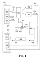
- Fig. 4 is a block diagram of an apparatus for controlling a yaw angle of a wind turbine with respect to the incoming wind direction by adjusting the pitch angle of rotor blades as a function of wind direction according to a second embodiment.
- the adjustment apparatus of Fig. 4 includes a second processing unit 406 which is used to provide the pitch angle control signal 508 for the pitch control unit 405. It is noted that components which have been described already with reference to Fig. 3 are not described again in order to avoid a redundant description.
- the wind turbine 100 includes a modified sensor device 200, wherein in addition to the wind direction sensor 201 and the yaw angle sensor 202 a yaw momentum sensor 203 is provided.
- the yaw momentum sensor 203 outputs a yaw momentum signal 506 which is supplied to a signal adding unit 404.
- the first processing unit 401 calculates a set signal 505 as a function of the wind direction signal 501 and the yaw angle signal 502 input into the first processing unit 401.
- This set signal 505 is dependent on a difference between the actual wind direction 105 ( Fig. 1 ) and the yaw angle signal 502 provided by the yaw angle sensor 202.
- the yaw angle signal 502 represents the actual yaw angle of the wind turbine 100.
- the set signal 505 corresponds to a set momentum which would be appropriate in the absence of a yaw momentum caused by the wind at the location of the wind turbine 100. If a yaw momentum is measured by the yaw momentum sensor 203 of the sensor device 200, this momentum may be subtracted from the momentum represented by the set signal 505.
- the different signal 507 difference momentum signal
- the second processing unit 406 which provides the pitch angle control signal 508 such that, via the pitch control unit 405, a pitch angle driver signal 509 can be provided in order to provide a pitch angle adjustment such that the machine nacelle 103 of the wind turbine 100 is rotated with respect to the wind direction 105.
- the step of calculating the set signal for the yaw angle modification is based on the determination of an angle difference between the measured wind direction and the measured yaw angle.
- the step of calculating the set signal for the yaw angle modification and the step of calculating the pitch angle of the rotor blades as a function of the set signal and the measured yaw momentum are performed by means of the same processing unit.
- the second processing unit 406 is adapted to calculate the pitch angle control signals 508 for the pitch adjustment as a function of the set signal 505 and the measured yaw momentum, i.e. the yaw momentum signal 506.
- the pitch control unit 405 is adapted to supply the pitch angle driver signal 509 to the pitch angle adjustment 301 of the actuator device 300 in order to control the pitch angle 108 of the rotor blades 101. It is noted that this embodiment is not restricted to the pitch angle control of a specific rotor blade, i.e. one or more of the plurality of rotor blades 101 may be controlled in order to provide a yaw momentum 107 which can change the yaw angle 106.
- the actuator device 300 further includes the yaw angle adjustment unit 302 which is adapted to adjust the yaw angle 106 in cooperation with the actual yaw momentum measured by the yaw momentum sensor 203.
- Fig. 5 is a flow diagram of a method for adjusting the yaw angle of a wind turbine, wherein the method is performed in an apparatus shown in Fig. 3 .
- the procedure is started.
- the wind direction is measured by the wind direction sensor 201 shown in Fig. 3 .
- the operation proceeds to a step S3, where the yaw angle, i.e. the actual yaw angle is measured by the yaw angle sensor 202 shown in the sensor device 200 of Fig. 3 .
- the pitch angle 108 is calculated by means of the processing unit 401 shown in Fig. 3 .
- the steps S2 and S3 are carried out in once in that the wind direction sensor 201 outputs the deviation between the wind direction and the actual orientation of the nacelle axis.
- the pitch angle 108 is such that a desired yaw momentum 107 is provided in order to rotate the machine nacelle 103 into an appropriate position with respect to the wind direction 105.
- a modified yaw angle is measured. It is noted that a yaw angle adjustment may be provided using either a yaw momentum generated by the yaw angle adjustment unit 302 in combination with a yaw momentum generated by an appropriate pitch angle adjustment or by a yaw momentum generated by an appropriate pitch angle adjustment alone.
- step S7 it is determined, whether the modified yaw angle is suited for the measured wind direction or not.
- step S7 it is determined whether the orientation of the wind turbine with respect to the wind direction 105 at the location of the wind turbine 100 is adapted for maximum energy conversion efficiency (conversion of wind energy to electrical energy, Fig. 1 ).
- step S7 If it is determined at step S7 that the modified yaw angle is not suited for the measured wind direction ("NO"), the operation proceeds to step S2 mentioned above. Afterwards the steps S2 to S6 are repeated and a further determination is performed at step S7.
- step S7 If it is determined at step S7 that the modified yaw angle is suited for the measured wind direction ("YES") the operation proceeds to a step S8 where the procedure is ended.
- Fig. 6 is a flow diagram of a method for adjusting the yaw angle of a turbine, wherein the method is performed using an apparatus which has been described above and which is shown in Fig. 4 .
- the step S3 is divided into two separate sub-steps S3a and S3b such that besides the yaw angle (step S3a), the yaw momentum is measured in a step S3b.
- step S1 the wind direction is measured in step S3 as before. Then the yaw angle and the yaw momentum are measured in steps S3a and S3b. Then the operation proceeds to step S4, where the pitch angle is calculated as a function of the wind direction, which has been determined in step S2, as a function of the yaw angle, which has been determined in step S3a, and as a function of the yaw momentum, which has been determined in the step S3b.
- step S5 the pitch angle of the rotor blades is adjusted in accordance with the measured parameters.
- step S6 a modified yaw angle is provided, and this yaw angle is measured at step S6.
- step S7 it is determined whether the modified yaw angle is suited for the measured wind direction or not. If the modified yaw angle is not suited for the measured wind direction ("NO"), the operation proceeds to step S2 described above. Then the steps S2, S3a, S3b, S4, S5 and S6 explained above are repeated.
- step S7 If it is determined at step S7, that the modified yaw angle is suited for the measured wind direction, i.e. the rotational position of the wind turbine about the central axis of the tubular tower 102 is such that maximum wind energy may be converted (“YES"), the operation proceeds to step S8 and is ended.
- the method for adjusting the yaw angle 106 from an actual yaw angle to a desired yaw angle comprises the step of determining a yaw mode as a function of the measured wind direction 105, a measured wind speed and the measured yaw angle 106.
- the yaw mode is at least one of (i) a no-yaw-adjustment-mode, wherein the yaw angle 106 is not adjusted, (ii) a delayed-yaw-adjustment-mode, wherein the yaw angle 106 is adjusted a predetermined time delay after the wind direction 105, the wind speed and the yaw angle 106 have been measured, (iii) a fixed-pitching-mode, wherein a pitch angle 108 of the at least one rotor blade is fixed and a yaw momentum 107 is generated by a wind resistance force of the at least one rotor blade, for changing the yaw angle 106 from the actual yaw angle to the desired yaw angle, and (iv) a normal yaw mode, wherein a pitch angle 108 of the at least one rotor blade is calculated as a function of the measured wind 105 direction and the measured yaw angle, and the pitch angle 106 of
- the normal yaw mode (iv) may be supported by driving at least one yaw motor and/or at least one yaw brake of the wind turbine in order to provide a high-speed-yaw-mode.
Landscapes
- Engineering & Computer Science (AREA)
- Life Sciences & Earth Sciences (AREA)
- Sustainable Development (AREA)
- Sustainable Energy (AREA)
- Chemical & Material Sciences (AREA)
- Combustion & Propulsion (AREA)
- Mechanical Engineering (AREA)
- General Engineering & Computer Science (AREA)
- Physics & Mathematics (AREA)
- Fluid Mechanics (AREA)
- Wind Motors (AREA)
Abstract
Description
- The present invention relates to wind turbines including a rotor having a plurality of rotor blades attached to a hub, and especially relates to a method and an apparatus for adjusting a yaw angle of a wind turbine with respect to the wind direction at the location of the wind turbine.
- Conventionally a wind turbine includes yaw brake control units and yaw motor control units in order to provide yaw brake driver signals and yaw motor driver signals which are used to adjust, in cooperation with a yaw angle adjustment unit, the yaw angle of the entire wind turbine. Furthermore wind turbines include yaw momentum sensors in order to measure a yaw momentum of the wind turbine. These kind of measurements usually are carried out in order to reduce the load on different components like main shaft and hub by adding interdependent or independent pitch offsets to each rotor blade. In order to reduce the load most effectively the yawing momentum is controlled to zero by adjusting the yaw angle of the wind turbine using the yaw angle adjustment unit.
- Wind turbines are of increasing importance as an environmentally safe and relatively inexpensive energy source. Thus an increased demand for an improved wind turbine performance has let to efforts concerning an optimum adjustment of the yaw angle with respect to the wind direction at the location of the wind turbine. As the wind direction at the location of the wind turbine may rapidly change, the yaw adjustment unit has to provide a reliable adjustment of the yaw angle even for a varying wind direction. Wind turbines include actuator devices such as yaw motors and yaw brakes in order to rotate a machine nacelle with respect to the wind direction at the location of the wind turbine. This kind of actuator devices are usually large electrical drives with gear boxes. These systems are complicated and expensive because they have to provide a torque required to orientate the wind turbine towards the incoming wind direction.
- According to a first aspect of the invention a method is provided for adjusting a yaw angle of a wind turbine from an actual yaw angle to a desired yaw angle, wherein the wind turbine includes a rotor having at least one rotor blade attached to a hub, the method including measuring a wind direction at the location of the wind turbine, measuring the yaw angle of the wind turbine and/or a wind direction relative to the nacelle orientation, calculating a pitch angle of the at least one rotor blade as a function of the measured wind direction and the measured yaw angle and/or a wind direction relative to the nacelle orientation, and adjusting the pitch angle of the at least one rotor blade according to the calculated pitch angle such that a yaw momentum is generated for changing the yaw angle from the actual yaw angle to the desired yaw angle.
- According to a second aspect of the present invention a method is provided for adjusting a yaw angle of a wind turbine from an actual yaw angle to a desired yaw angle, wherein the wind turbine includes a rotor having a plurality of rotor blades attached to a hub, the method including measuring a wind direction at the location of the wind turbine, measuring the yaw angle of the wind turbine and/or a wind direction relative to the nacelle orientation, calculating a set signal for a yaw angle modification as a function of the measured wind direction and the measured yaw angle and/or a wind direction relative to the nacelle orientation, measuring a yaw momentum of the wind turbine, calculating a pitch angle of the rotor blades as a function of the set signal and the measured yaw momentum, and adjusting the pitch angle of the rotor blades according to the calculated pitch angle such that a yaw momentum is generated for changing the yaw angle from the actual yaw angle to the desired yaw angle.
- According to a third aspect of the present invention a wind turbine is provided including a rotor having a plurality of rotor blades attached to a hub, said wind turbine further including a sensor device adapted to measure a wind direction at the location of the wind turbine, a first processing unit for calculating a set signal for a yaw angle modification from an actual yaw angle to a desired yaw angle as a function of the measured wind direction and the actual yaw angle and/or a wind direction relative to the nacelle orientation, and an actuator device adapted to adjust a pitch angle of at least one of the plurality of rotor blades as a function of the set signal such that a yaw momentum is generated for changing the yaw angle from the actual yaw angle to the desired yaw angle.
- Various aspects, advantages and features of the present invention are apparent from the dependent claims, the description and the accompanying drawings, in which:
-
Fig. 1 shows a schematic side view of a wind turbine oriented with respect to an incoming wind direction at the location of the wind turbine; -
Fig. 2 is a schematic top view of a wind turbine indicating a yaw angle; -
Fig. 3 a block diagram of an apparatus for controlling a yaw angle of the wind turbine with respect to an incoming wind direction by means of an adjustment of the pitch angle of rotor blades; -
Fig. 4 a block diagram of an apparatus for controlling a yaw angle of a wind turbine with respect to the incoming wind direction by adjusting the pitch angle of rotor blades as a function of wind direction and yaw momentum; -
Fig. 5 is a flow chart of a method for the adjusting the yaw angle of a wind turbine as a function of an actual wind direction and an actual yaw angle, the method being performed by an apparatus shown inFig. 3 ; and -
Fig. 6 is a flow chart showing a method for adjusting the yaw angle as a function of the actual wind direction, the actual yaw angel and a yaw momentum measured by a yaw momentum sensor, the method being performed by an apparatus shown inFig. 4 . - Reference will now be made in detail to the various embodiments of the invention, one or more examples of which are illustrated in the figures. Each example is provided by way of explanation of the invention, and is not meant as a limitation of the invention. For example, features illustrated or described as part of one embodiment can be used on or in conjunction with other embodiments to yield yet a further embodiment. It is intended that the present invention includes such modifications and variations.
- In view of the above, a method and an apparatus for adjusting the yaw angle of a wind turbine are provided. At the location of the wind turbine the wind direction is measured by means of a wind direction sensor provided at the wind turbine, a yaw angle of the wind turbine is measured by means of a yaw angle sensor provided at the wind turbine, and a pitch angle control signal for controlling a pitch angle of at least one rotor blade at a function of the measured wind direction and the measured yaw angle is calculated by means of a processing unit such that a yaw momentum is generated for changing the measured yaw angle as a function of the measured wind direction and of the measured yaw angle.
- Using this pitch control signal a pitch angle of the rotor blades can be adjusted. Thus a defined yaw momentum offset may be used to support the yaw angle adjustment unit of an actuator device of the wind turbine in adjusting the yaw angle. In order to provide such kind of yaw momentum offsets, interdependent pitch offsets to each blade are added. Negative or positive yaw moments can be applied in order to support both yaw directions. It is thus an advantage that the actuator device including yaw brakes and yaw motors as well as gear boxes and gear rings can be designed with components which consume less power and therefore are less expensive.
- According to the gist idea of certain aspects of the invention the method includes the steps of (i) measuring an actual yaw momentum, (ii) controlling the yaw momentum to zero, and (iii) in case of a desired change in yaw position, controlling the yaw momentum to a different set point that is suited to support the yaw drives by means of an interdependent pitch offset.
-
Fig. 1 is a schematic view of awind turbine 100 having amachine nacelle 103, which is rotatably mounted on top of atubular tower 102. Thewind turbine 100 further includes a rotor having ahub 104 and threerotor blades 101. Thehub 104 is the central part of the rotor and therotor blades 101 extend outwardly from the hub. Although thewind turbine 100 illustrated inFig. 1 includes threerotor blades 101, any number ofrotor blades 101 may be provided. Thenacelle 103 which is located on top of thetubular tower 102 can be rotated about a central axis of thetubular tower 102. The orientation of themachine nacelle 103 with respect to the central axis of thetubular tower 102 is referred to as theyaw angle 106 which is further elucidated inFig. 2 below. Depending on the orientation of thenacelle 103 with respect to the incoming wind direction 105 ayaw momentum 107 is applied to the wind turbine, especially to the rotor and thenacelle 103. Theyaw momentum 107 drives themachine nacelle 103 in a direction such that the axis of the main shaft of the rotor may be oriented towards theincoming wind direction 105. It is noted that theyaw momentum 107 is referred to in a vector representation such that the momentum acts about the central axis of thetubular tower 102. -
Fig. 2 is a schematic top view of thewind turbine 100 indicating theyaw angle 106 which this case is exemplary measured from an axis of theincoming wind direction 105. If themachine nacelle 103 is rotated theyaw angle 106 may be changed. - A
pitch angle 108 of at least onerotor blade 101 is controlled according to the method disclosed. It is noted thatreference numeral 108 inFig. 1 is related to the rotation of arotor blade 101 about its longitudinal axis. Furthermore, as will be described herein below, apitching momentum 109 of the wind turbine may be compensated for by the adjustment of thepitch angle 108 of at least one of the plurality ofrotor blades 101. Arotation sensor 110 is mounted on the axis of the rotor in order to be able to adjust thepitch angle 108 with respect to a given rotational position of the rotor. -
Fig. 3 is a block diagram of an apparatus for adjusting the yaw angle of a wind turbine according to a first embodiment. As shown inFig. 3 , thewind turbine 100 includes asensor device 200 and anactuator device 300. Thesensor device 200 of thewind turbine 100 shown inFig. 3 includes awind direction sensor 201 and ayaw angle sensor 202 provided at thewind turbine 100. Thewind direction sensor 201 provides awind direction signal 501 wherein theyaw angle sensor 202 provides ayaw angle signal 502. Thewind direction signal 501 and theyaw angle signal 502 are supplied to afirst processing unit 401 which processes the input signals. - The
first processing unit 401 provides driver signals for a yawbrake control unit 402 and a yawmotor control unit 403. These control units are used for an adjustment of the yaw angle of the wind turbine. In order to provide an adjustment of the yaw angle, the yawbrake control unit 402 outputs a yawbrake driver signal 503 wherein the yaw motor control unit outputs a yawmotor driver signal 504. Bothsignals angle adjustment unit 302 provided in theactuator device 300 of thewind turbine 100. Theactuator device 300 is used for adjusting the yaw angle with respect to the incoming wind direction 105 (Fig. 1 ). - Furthermore the
first processing unit 401 comprises ayaw speed controller 401 a which is used to control the speed at which theyaw angle 106 is modified. In addition to that theyaw momentum 107 is controlled as a function of an actual yaw speed at which the yaw angle is modified, by using a yaw speed controller. - According an embodiment the step of calculating the pitch angle control signal for controlling the pitch angle of the at least one rotor blade in order to change the yaw angle is based on the predetermination of an angle difference between the measured wind direction and the measured yaw angle.
- According to another embodiment the adjustment of the pitch angle of the at least one rotor blade is dependent on the rotational position of the rotor blade.
- As yaw moments 107 (
Fig. 1 ) may be very large, the yawangle adjustment unit 302 of theactuator device 300 of conventional wind turbines is very expensive, because large torques have to be provided. The apparatus for adjusting the yaw angle of a wind turbine according to this embodiment has the advantage, that in addition to, or instead of, the yaw angle adjustment unit 302 a pitchangle adjustment unit 301 of theactuator device 300 of thewind turbine 100 is used to introduce ayaw momentum 107 by controlling thepitch angle 108 of at least one rotor blade 101 (seeFig. 1 ). It is noted thatreference numeral 108 inFig. 1 is related to the rotation of arotor blade 101 about the longitudinal axis of the rotor blade 101 (the axis of therotor blades 101 is not shown inFig.1 ). - Thus by adjusting the pitch angle of one or more rotor blades of the plurality of rotor blades it is possible to provide different flow resistances with respect to the incoming wind at different rotational positions. This results in a
momentum 107 which gives rise to the change of theyaw angle 106. - The yaw
angle adjustment unit 302 of theactuator device 300 is used to adjust theyaw angle 106 even in the absence of ayaw momentum 107 such that the axis of the rotor of thewind turbine 100 may be directed towards theincoming wind direction 105. If anadditional yaw momentum 107 is provided by an appropriate pitch angle adjustment, the yawangle adjustment unit 302 may be driven with less driving energy. - To this end, as shown in
Fig. 3 , thefirst processing unit 401 outputs a pitchangle control signal 508 which is supplied to apitch control unit 405. Thepitch control unit 405 provides a pitchangle driver signal 509 for the pitchangle adjustment unit 301. It is noted that the pitch angle adjustment may be different for eachrotor blade 101 and also may be different at different rotational positions of eachindividual rotor blade 101. The rotational positions of therotor blades 101 may be determined by using arotation sensor 110 mounted on the axis of the rotor. - According to yet another embodiment the adjustment of the pitch angle of the plurality of rotor blades is performed independently for each rotor blade. Furthermore it may be an advantage that the adjustment of the pitch angle of the at least one rotor blade is dependent on the rotational position of the rotor blade.
-
Fig. 4 is a block diagram of an apparatus for controlling a yaw angle of a wind turbine with respect to the incoming wind direction by adjusting the pitch angle of rotor blades as a function of wind direction according to a second embodiment. In addition to the apparatus shown inFig. 3 the adjustment apparatus ofFig. 4 includes asecond processing unit 406 which is used to provide the pitchangle control signal 508 for thepitch control unit 405. It is noted that components which have been described already with reference toFig. 3 are not described again in order to avoid a redundant description. - As shown in
Fig. 4 , thewind turbine 100 according to the second embodiment of this embodiment includes a modifiedsensor device 200, wherein in addition to thewind direction sensor 201 and the yaw angle sensor 202 ayaw momentum sensor 203 is provided. Theyaw momentum sensor 203 outputs ayaw momentum signal 506 which is supplied to asignal adding unit 404. In the apparatus shown inFig. 4 thefirst processing unit 401 calculates aset signal 505 as a function of thewind direction signal 501 and theyaw angle signal 502 input into thefirst processing unit 401. Thisset signal 505 is dependent on a difference between the actual wind direction 105 (Fig. 1 ) and theyaw angle signal 502 provided by theyaw angle sensor 202. - The
yaw angle signal 502 represents the actual yaw angle of thewind turbine 100. Theset signal 505 corresponds to a set momentum which would be appropriate in the absence of a yaw momentum caused by the wind at the location of thewind turbine 100. If a yaw momentum is measured by theyaw momentum sensor 203 of thesensor device 200, this momentum may be subtracted from the momentum represented by theset signal 505. Thus the different signal 507 (difference momentum signal) is supplied to thesecond processing unit 406 which provides the pitchangle control signal 508 such that, via thepitch control unit 405, a pitchangle driver signal 509 can be provided in order to provide a pitch angle adjustment such that themachine nacelle 103 of thewind turbine 100 is rotated with respect to thewind direction 105. - According to yet another embodiment the step of calculating the set signal for the yaw angle modification is based on the determination of an angle difference between the measured wind direction and the measured yaw angle. Typically the step of calculating the set signal for the yaw angle modification and the step of calculating the pitch angle of the rotor blades as a function of the set signal and the measured yaw momentum are performed by means of the same processing unit.
- Typically the
second processing unit 406 is adapted to calculate the pitch angle control signals 508 for the pitch adjustment as a function of theset signal 505 and the measured yaw momentum, i.e. theyaw momentum signal 506. - According to yet another embodiment the
pitch control unit 405 is adapted to supply the pitchangle driver signal 509 to thepitch angle adjustment 301 of theactuator device 300 in order to control thepitch angle 108 of therotor blades 101. It is noted that this embodiment is not restricted to the pitch angle control of a specific rotor blade, i.e. one or more of the plurality ofrotor blades 101 may be controlled in order to provide ayaw momentum 107 which can change theyaw angle 106. - According to yet another embodiment the
actuator device 300 further includes the yawangle adjustment unit 302 which is adapted to adjust theyaw angle 106 in cooperation with the actual yaw momentum measured by theyaw momentum sensor 203. -
Fig. 5 is a flow diagram of a method for adjusting the yaw angle of a wind turbine, wherein the method is performed in an apparatus shown inFig. 3 . At step S1 the procedure is started. At step S2 the wind direction is measured by thewind direction sensor 201 shown inFig. 3 . Then the operation proceeds to a step S3, where the yaw angle, i.e. the actual yaw angle is measured by theyaw angle sensor 202 shown in thesensor device 200 ofFig. 3 . From the measured yaw angle and the measured wind direction (steps S2 and S3), at step S4, thepitch angle 108 is calculated by means of theprocessing unit 401 shown inFig. 3 . In a typical embodiment, the steps S2 and S3 are carried out in once in that thewind direction sensor 201 outputs the deviation between the wind direction and the actual orientation of the nacelle axis. Thepitch angle 108 is such that a desiredyaw momentum 107 is provided in order to rotate themachine nacelle 103 into an appropriate position with respect to thewind direction 105. - Then the operation proceeds to a step S5 where the pitch angle of the rotor blades is adjusted in accordance with the pitch
angle control signal 508 provided by theprocessing unit 401. The modification of thepitch angle 108 of the rotor blades results in anadditional yaw momentum 107 such that theyaw angle 106 is modified in a desired manner. At step S6 a modified yaw angle is measured. It is noted that a yaw angle adjustment may be provided using either a yaw momentum generated by the yawangle adjustment unit 302 in combination with a yaw momentum generated by an appropriate pitch angle adjustment or by a yaw momentum generated by an appropriate pitch angle adjustment alone. - The operation proceeds to a step S7 where it is determined, whether the modified yaw angle is suited for the measured wind direction or not. In other words, at step S7 it is determined whether the orientation of the wind turbine with respect to the
wind direction 105 at the location of thewind turbine 100 is adapted for maximum energy conversion efficiency (conversion of wind energy to electrical energy,Fig. 1 ). - If it is determined at step S7 that the modified yaw angle is not suited for the measured wind direction ("NO"), the operation proceeds to step S2 mentioned above. Afterwards the steps S2 to S6 are repeated and a further determination is performed at step S7.
- If it is determined at step S7 that the modified yaw angle is suited for the measured wind direction ("YES") the operation proceeds to a step S8 where the procedure is ended.
-
Fig. 6 is a flow diagram of a method for adjusting the yaw angle of a turbine, wherein the method is performed using an apparatus which has been described above and which is shown inFig. 4 . As compared to the method depicted inFig. 5 the step S3 is divided into two separate sub-steps S3a and S3b such that besides the yaw angle (step S3a), the yaw momentum is measured in a step S3b. - Thus after the start of the procedure at step S1, the wind direction is measured in step S3 as before. Then the yaw angle and the yaw momentum are measured in steps S3a and S3b. Then the operation proceeds to step S4, where the pitch angle is calculated as a function of the wind direction, which has been determined in step S2, as a function of the yaw angle, which has been determined in step S3a, and as a function of the yaw momentum, which has been determined in the step S3b.
- Then the operation proceeds to step S5, where the pitch angle of the rotor blades is adjusted in accordance with the measured parameters. As a result, a modified yaw angle is provided, and this yaw angle is measured at step S6. In step S7 it is determined whether the modified yaw angle is suited for the measured wind direction or not. If the modified yaw angle is not suited for the measured wind direction ("NO"), the operation proceeds to step S2 described above. Then the steps S2, S3a, S3b, S4, S5 and S6 explained above are repeated.
- If it is determined at step S7, that the modified yaw angle is suited for the measured wind direction, i.e. the rotational position of the wind turbine about the central axis of the
tubular tower 102 is such that maximum wind energy may be converted ("YES"), the operation proceeds to step S8 and is ended. - In addition to the steps described above with reference to
Figs. 5 and6 , the method for adjusting theyaw angle 106 from an actual yaw angle to a desired yaw angle comprises the step of determining a yaw mode as a function of the measuredwind direction 105, a measured wind speed and the measuredyaw angle 106. - According to another embodiment the yaw mode is at least one of (i) a no-yaw-adjustment-mode, wherein the
yaw angle 106 is not adjusted, (ii) a delayed-yaw-adjustment-mode, wherein theyaw angle 106 is adjusted a predetermined time delay after thewind direction 105, the wind speed and theyaw angle 106 have been measured, (iii) a fixed-pitching-mode, wherein apitch angle 108 of the at least one rotor blade is fixed and ayaw momentum 107 is generated by a wind resistance force of the at least one rotor blade, for changing theyaw angle 106 from the actual yaw angle to the desired yaw angle, and (iv) a normal yaw mode, wherein apitch angle 108 of the at least one rotor blade is calculated as a function of the measuredwind 105 direction and the measured yaw angle, and thepitch angle 106 of the rotor blades is adjusted according to the calculated pitch angle such that ayaw momentum 107 is generated for changing the yaw angle from the actual yaw angle to the desired yaw angle. - The normal yaw mode (iv) may be supported by driving at least one yaw motor and/or at least one yaw brake of the wind turbine in order to provide a high-speed-yaw-mode.
- This written description uses examples to disclose the invention, including the preferred mode, and also to enable any person skilled in the art to make and use the invention. While the invention has been described in terms of various specific embodiments, those skilled in the art will recognize that the invention can be practiced with modification within the spirit and scope of the claims. Especially, mutually non-exclusive features of the embodiments described above may be combined with each other. The patentable scope of the invention is defined by the claims, and may include other examples that occur to those skilled in the art. Such other examples are intended to be within the scope of the claims if they have structural elements that do not differ from the literal language of the claims, or if they include equivalent structural elements with insubstantial differences from the literal languages of the claims.
- Various aspects and embodiments of the present invention are defined by the following numbered clauses
- 1. A method for adjusting a yaw angle of a wind turbine from an actual yaw angle to a desired yaw angle, the wind turbine comprising a rotor having at least one rotor blade attached to a hub, the method comprising:
- a) measuring a wind direction at the location of the wind turbine;
- b) measuring the yaw angle of the wind turbine and/or a wind direction relative to the nacelle orientation;
- c) calculating a pitch angle of the at least one rotor blade as a function of the measured wind direction and the measured yaw angle and/or a wind direction relative to the nacelle orientation; and
- d) adjusting the pitch angle of the rotor blades according to the calculated pitch angle such that a yaw momentum is generated for changing the yaw angle from the actual yaw angle to the desired yaw angle.
- 2. The method in accordance with clause 1, wherein the step of calculating the pitch angle of the at least one rotor blade is based on the determination of an angle difference between the measured wind direction and the measured yaw angle and/or a wind direction relative to the nacelle orientation.
- 3. The method in accordance with any preceding clause, wherein the adjustment of the pitch angle of the at least one rotor blade is dependent on the rotational position of the rotor blade.
- 4. The method in accordance with any preceding clause, wherein the wind turbine comprises a plurality of rotor blades and the pitch angle is independently adjusted for each rotor blade out of the plurality of rotor blades.
- 5. The method in accordance with any preceding clause, wherein the adjustment of the pitch angle of the at least one rotor blade is performed with respect to an incoming wind direction measured by a wind direction sensor.
- 6. The method in accordance with any preceding clause, wherein the adjustment of the yaw angle is supported by driving at least one yaw motor and at least one yaw brake of the wind turbine.
- 7. A method for adjusting a yaw angle of a wind turbine from an actual yaw angle to a desired yaw angle, the wind turbine comprising a rotor having a plurality of rotor blades attached to a hub, the method comprising:
- a) measuring a wind direction at the location of the wind turbine;
- b) measuring the yaw angle of the wind turbine;
- c) calculating a set signal for a yaw angle modification as a function of the measured wind direction and the measured yaw angle;
- d) measuring a yaw momentum of the wind turbine;
- e) calculating a pitch angle of the rotor blades as a function of the set signal and the measured yaw momentum; and
- f) adjusting the pitch angle of the rotor blades according to the calculated pitch angle such that a yaw momentum is generated for changing the yaw angle from the actual yaw angle to the desired yaw angle.
- 8. The method in accordance with any preceding clause, wherein the step of calculating the set signal for the yaw angle modification is based on the determination of an angle difference between the measured wind direction and the measured yaw angle and/or the relative wind direction at the nacelle.
- 9. The method in accordance with any preceding clause, wherein the step of calculating the set signal for the yaw angle modification and the step of calculating the pitch angle of the rotor blades as a function of the set signal and the measured yaw momentum is performed by means of one single processing unit.
- 10. The method in accordance with any preceding clause, wherein the adjustment of the pitch angle of the at least one rotor blade is dependent on the rotational position of the rotor blade.
- 11. The method in accordance with any preceding clause, wherein the adjustment of the pitch angle of the plurality of rotor blades is performed independently for each rotor blade.
- 12. The method in accordance with any preceding clause, wherein the adjustment of the pitch angle of the plurality of rotor blades is performed with respect to an incoming wind direction measured by a wind direction sensor.
- 13. The method in accordance with any preceding clause, wherein the adjustment of the yaw angle is supported by driving at least one yaw motor and at least one yaw brake of the wind turbine.
- 14. The method in accordance with any preceding clause, wherein a yaw momentum of the wind turbine is compensated by the adjustment of the pitch angle of at least one of the plurality of rotor blades.
- 15. A wind turbine comprising a rotor having a plurality of rotor blades attached to a hub, said wind turbine further comprising:
- a) a sensor device adapted to measure a wind direction at the location of the wind turbine;
- b) a first processing unit for calculating a set signal for a yaw angle modification from an actual yaw angle to a desired yaw angle as a function of the measured wind direction and the actual yaw angle and/or a wind direction relative to the nacelle orientation; and
- c) an actuator device adapted to adjust a pitch angle of at least one of the plurality of rotor blades as a function of the set signal such that a yaw momentum is generated for changing the yaw angle from the actual yaw angle to the desired yaw angle.
- 16. The wind turbine in accordance with clause 15, wherein the sensor device further comprises a yaw angle sensor for measuring the actual yaw angle.
- 17. The wind turbine in accordance with clause 15 or 16, wherein the sensor device further comprises a yaw momentum sensor for measuring an actual yaw momentum.
- 18. The wind turbine in accordance with any one of clauses 15 to 17, wherein a second processing unit is provided which is adapted to calculate a pitch angle control signal for a pitch adjustment as a function of the set signal and the measured yaw momentum.
- 19. The wind turbine in accordance with any one of clauses 15 to 18, wherein a pitch control unit is provided in order to supply a pitch angle driver signal as a function of the control signal for the actuator device in order to control the pitch angle of the rotor blades.
- 20. The wind turbine in accordance with any one of clauses 15 to 19, wherein the actuator device further comprises a yaw angle adjustment unit for adjusting the yaw angle in cooperation with the actual yaw momentum.
- 21. A method for adjusting a yaw angle of a wind turbine from an actual yaw angle to a desired yaw angle, the wind turbine comprising a rotor having at least one rotor blade attached to a hub, the method comprising:
- a) measuring a wind direction at the location of the wind turbine;
- b) measuring a wind speed at the location of the wind turbine;
- c) measuring the yaw angle of the wind turbine;
- d) determining a yaw mode as a function of the measured wind direction, the measured wind speed and the measured yaw angle.
- 22. The method in accordance with clause 21, wherein the yaw mode is at least one of
- (i) a no-yaw-adjustment-mode, wherein the yaw angle is not adjusted;
- (ii) a delayed-yaw-adjustment-mode, wherein the yaw angle is adjusted a predetermined time delay after the wind direction, the wind speed and the yaw angle have been measured;
- (iii) a fixed-pitching-mode, wherein a pitch angle of the at least one rotor blade is fixed and a yaw momentum is generated by a wind resistance force of the at least one rotor blade, for changing the yaw angle from the actual yaw angle to the desired yaw angle; and
- (iv) a normal yaw mode, wherein a pitch angle of the at least one rotor blade is calculated as a function of the measured wind direction and the measured yaw angle and the pitch angle of the rotor blades is adjusted according to the calculated pitch angle such that a yaw momentum is generated for changing the yaw angle from the actual yaw angle to the desired yaw angle.
- 23. The method in accordance with clause 21 or 22, wherein the normal yaw mode is supported by driving at least one yaw motor and/or at least one yaw brake of the wind turbine in order to provide a high-speed-yaw-mode.
- 24. The method in accordance with any one of clauses 21 to 23, wherein the yaw momentum is controlled as a function of an actual yaw speed at which the yaw angle is modified, by using a yaw speed controller.
- 25. A method for adjusting a yaw angle of a wind turbine from an actual yaw angle to a desired yaw angle, the method comprising:
- yawing a nacelle using a pitch of a rotor blade of a wind turbine as a function of a measured wind direction, a measured wind speed, and a measured yaw angle.
Claims (10)
- A method for adjusting a yaw angle (106) from an actual yaw angle to a desired yaw angle, of a wind turbine (100) comprising a rotor having a plurality of rotor blades (101) and a hub (104), the method comprising:a) measuring a wind direction (105) at the location of the wind turbine (100);b) measuring the yaw angle (106) of the wind turbine (100) and/or a wind direction relative to the nacelle orientation;c) calculating a pitch angle (108) of at least one rotor blade (101) as a function of the measured wind direction (105) and the measured yaw angle and/or a wind direction relative to the nacelle orientation; andd) adjusting the pitch angle (108) of the rotor blades (101) according to the calculated pitch angle (108) such that a yaw momentum (107) is generated for changing the yaw angle (106) from the actual yaw angle to the desired yaw angle.
- The method in accordance with claim 1, wherein the step of calculating the pitch angle (108) of at least one rotor blade (101) is based on the determination of an angle difference between the measured wind direction (105) and the measured yaw angle.
- The method in accordance with any preceding claim, wherein the adjustment of the pitch angle (108) of the at least one rotor blade (101) is performed in dependence of the rotational position of the rotor blade (101) and/or independently for each rotor blade (101).
- The method in accordance with any preceding claim, wherein the adjustment of the yaw angle (106) is supported by driving at least one yaw motor and at least one yaw brake of the wind turbine (100).
- The method in accordance with any preceding claim, wherein the method further comprises:a) calculating a set signal (505) for a yaw angle modification from the actual yaw angle to the desired yaw angle, as a function of the measured wind direction (105) and the measured yaw angle;b) measuring a yaw momentum (107) of the wind turbine (100);e) calculating the pitch angle (108) of the rotor blades (101) as a function of the set signal (505) and the measured yaw momentum (107).
- The method in accordance with claim 5, wherein the step of calculating the set signal (505) for the yaw angle modification is based on the determination of an angle difference between the measured wind direction (105) and the measured yaw angle and/or a wind direction relative to the nacelle orientation.
- The method in accordance with any preceding claim, wherein a yaw momentum (109) of the wind turbine (100) is compensated by the adjustment of the pitch angle (108) of at least one of the plurality of rotor blades (101).
- A wind turbine (100) comprising a rotor having a plurality of rotor blades (101) and a hub (104), said wind turbine (100) further comprising:a) a sensor device (200) adapted to measure a wind direction (105) at the location of the wind turbine (100);b) a first processing unit (401) for calculating a set signal (505) for a yaw angle modification from an actual yaw angle to a desired yaw angle as a function of the measured wind direction (105) and the actual yaw angle and/or a wind direction relative to the nacelle orientation; andc) an actuator device (300) adapted to adjust a pitch angle (108) of at least one of the plurality of rotor blades (101) as a function of the set signal (505) such that a yaw momentum (107) is generated for changing the yaw angle (106) from the actual yaw angle to the desired yaw angle.
- The wind turbine (100) in accordance with claim 8, wherein the sensor device (200) further comprises a yaw angle sensor (202) for measuring the actual yaw angle and/or a yaw momentum sensor (203) for measuring an actual yaw momentum (107).
- The wind turbine (100) in accordance with claim 8 or claim 9, wherein the actuator device (300) further comprises a yaw angle adjustment unit (302) for adjusting the yaw angle (106) in cooperation with the actual yaw momentum (107).
Applications Claiming Priority (1)
| Application Number | Priority Date | Filing Date | Title |
|---|---|---|---|
| US12/199,052 US8353667B2 (en) | 2008-08-27 | 2008-08-27 | Method and apparatus for adjusting a yaw angle of a wind turbine |
Publications (3)
| Publication Number | Publication Date |
|---|---|
| EP2159415A2 true EP2159415A2 (en) | 2010-03-03 |
| EP2159415A3 EP2159415A3 (en) | 2012-02-22 |
| EP2159415B1 EP2159415B1 (en) | 2016-10-12 |
Family
ID=41066610
Family Applications (1)
| Application Number | Title | Priority Date | Filing Date |
|---|---|---|---|
| EP09167788.0A Not-in-force EP2159415B1 (en) | 2008-08-27 | 2009-08-13 | Method and apparatus for controlling the yaw angle of a wind turbine |
Country Status (3)
| Country | Link |
|---|---|
| US (1) | US8353667B2 (en) |
| EP (1) | EP2159415B1 (en) |
| CN (1) | CN101660492B (en) |
Cited By (11)
| Publication number | Priority date | Publication date | Assignee | Title |
|---|---|---|---|---|
| WO2013004244A3 (en) * | 2011-07-04 | 2013-04-18 | Vestas Wind Systems A/S | A method of yawing a rotor of a wind turbine |
| WO2014067661A3 (en) * | 2012-10-31 | 2014-06-26 | 2-B Energy B.V. | Method for aligning a yaw moment of a wind power plant by a yaw moment of the rotor |
| EP2530304A4 (en) * | 2010-01-27 | 2014-07-16 | Mitsubishi Heavy Ind Ltd | WIND ENERGY GENERATING DEVICE AND METHOD FOR CONTROLLING LACET ROTATION FOR WIND POWER GENERATING DEVICE |
| CN104343628A (en) * | 2014-08-27 | 2015-02-11 | 东北大学 | Variable pitch control method for wind turbine generator with dead-time compensation device |
| EP2754890A3 (en) * | 2013-01-14 | 2018-03-21 | General Electric Company | Method and Apparatus for Controlling an Operational Parameter of a Wind Turbine |
| EP3343027A1 (en) * | 2016-12-30 | 2018-07-04 | Acciona Windpower, S.A. | Method of reducing loads acting on a wind turbine yaw system |
| DE102018009231A1 (en) * | 2018-11-26 | 2020-05-28 | Senvion Gmbh | Method and system for operating a wind turbine |
| DE102018009230A1 (en) * | 2018-11-26 | 2020-05-28 | Senvion Gmbh | Method and system for operating a wind turbine |
| DE102018009232A1 (en) * | 2018-11-26 | 2020-05-28 | Senvion Gmbh | Method and system for operating a wind turbine |
| EP3879093A1 (en) * | 2020-03-10 | 2021-09-15 | Siemens Gamesa Renewable Energy A/S | Wind turbine comprising variable swept area and method of controlling a wind turbine |
| EP4632220A1 (en) * | 2024-04-09 | 2025-10-15 | Nabtesco Corporation | Controller, processing circuit, method, and non-transitory computer-readable medium for controlling wind power generation device |
Families Citing this family (30)
| Publication number | Priority date | Publication date | Assignee | Title |
|---|---|---|---|---|
| EP2017468A1 (en) * | 2007-07-20 | 2009-01-21 | Siemens Aktiengesellschaft | Method for wind turbine yaw control |
| CN101329825B (en) * | 2008-07-25 | 2010-09-01 | 许培元 | Windproof billboard and control method thereof |
| DE102009007935B4 (en) * | 2009-02-06 | 2011-06-30 | Lewandowski, Angela, 30159 | Device and method for the artificial extension of nails |
| SG182551A1 (en) * | 2010-01-19 | 2012-08-30 | Wattenberg Ind Llc | Low-profile power-generating wind turbine |
| GB2479413A (en) * | 2010-04-09 | 2011-10-12 | Vestas Wind Sys As | Wind Turbine Independent Blade Control Outside The Rated Output |
| CN102444543B (en) * | 2010-09-30 | 2013-10-09 | 华锐风电科技(集团)股份有限公司 | Method and device for judging unnecessary windward condition, and method and system for tracking wind |
| US8178989B2 (en) * | 2010-12-15 | 2012-05-15 | General Electric Company | System and methods for adjusting a yaw angle of a wind turbine |
| CN203685475U (en) * | 2011-01-31 | 2014-07-02 | 通用电气公司 | Wind turbine control system and wind turbine system |
| EP2520794B1 (en) * | 2011-05-03 | 2019-09-18 | Siemens Gamesa Renewable Energy A/S | Monitoring apparatus for checking a wind turbine in a wind farm for a yaw misalignment |
| DK177292B1 (en) * | 2011-06-30 | 2012-10-08 | Envision Energy Denmark Aps | A wind turbine and an associated yaw control method |
| US9234506B2 (en) * | 2011-10-14 | 2016-01-12 | Vestas Wind Systems A/S | Estimation of wind properties using a light detection and ranging device |
| US9217415B2 (en) * | 2011-10-14 | 2015-12-22 | Vestas Wind Systems A/S | Estimation of wind properties using a light detection and ranging device |
| US8317471B2 (en) | 2011-11-29 | 2012-11-27 | General Electric Company | Method for preventing rotor overspeed of a wind turbine |
| WO2013182201A1 (en) * | 2012-06-08 | 2013-12-12 | Vestas Wind Systems A/S | Wind turbine control |
| US20150076822A1 (en) * | 2013-09-13 | 2015-03-19 | Justin Creaby | Damping an oscillatory movement of a nacelle of a wind turbine |
| CN103835879B (en) * | 2014-02-11 | 2017-04-12 | 南京南瑞继保电气有限公司 | Draught fan yaw start discriminating method based on inverse time limit |
| JP6247957B2 (en) * | 2014-02-26 | 2017-12-13 | 三菱重工業株式会社 | Yaw control system and yaw control method for wind turbine generator |
| US9372201B2 (en) * | 2014-03-31 | 2016-06-21 | Alstom Renewable Technologies | Yaw and pitch angles |
| US10100812B2 (en) | 2014-06-30 | 2018-10-16 | General Electric Company | Methods and systems to operate a wind turbine system |
| CN105275745A (en) * | 2014-07-07 | 2016-01-27 | 深圳市福田区青少年科技教育协会 | Wind-driven generator capable of automatically adapting to wind direction |
| CN104314754B (en) * | 2014-08-20 | 2017-04-05 | 国家电网公司 | A kind of Yaw control method and yaw control system |
| EP3212927B1 (en) | 2014-10-31 | 2021-02-24 | General Electric Company | System and method for controlling the operation of a wind turbine |
| EP3225838A1 (en) * | 2016-03-30 | 2017-10-04 | Siemens Aktiengesellschaft | Method and arrangement for performing a wind direction measurement |
| US11168662B2 (en) | 2016-04-13 | 2021-11-09 | Vestas Wind Systems A/S | Control method for a wind turbine |
| ES2794827T3 (en) | 2016-06-30 | 2020-11-19 | Vestas Wind Sys As | Control method for a wind turbine |
| CN108457798A (en) * | 2018-02-11 | 2018-08-28 | 内蒙古久和能源装备有限公司 | A kind of wind generating set yaw error control method and system |
| US10612521B2 (en) * | 2018-03-05 | 2020-04-07 | General Electric Company | Wind turbine shadow flicker management system |
| US11193469B2 (en) * | 2019-03-19 | 2021-12-07 | 2-B Energy B.V. | Method for operating a wind turbine, wind turbine, and control means for a wind turbine |
| CN115773208A (en) * | 2021-09-06 | 2023-03-10 | 北京长征高科技有限公司 | A safety protection method for preventing twisted cable failure of wind power generating set |
| EP4321751A1 (en) * | 2022-08-09 | 2024-02-14 | Wobben Properties GmbH | Method for detecting an incorrect orientation of a rotor blade of a wind turbine |
Family Cites Families (8)
| Publication number | Priority date | Publication date | Assignee | Title |
|---|---|---|---|---|
| US4966525A (en) * | 1988-02-01 | 1990-10-30 | Erik Nielsen | Yawing device and method of controlling it |
| DE29715248U1 (en) * | 1997-08-25 | 1998-12-24 | Institut für Solare Energieversorgungstechnik Verein an der Universität Gesamthochschule Kassel eV, 34119 Kassel | Wind turbine |
| US6441507B1 (en) * | 2000-03-22 | 2002-08-27 | The Wind Turbine Company | Rotor pitch control method and apparatus for parking wind turbine |
| DE10106208C2 (en) * | 2001-02-10 | 2002-12-19 | Aloys Wobben | Wind turbine |
| US7004724B2 (en) | 2003-02-03 | 2006-02-28 | General Electric Company | Method and apparatus for wind turbine rotor load control based on shaft radial displacement |
| US7118339B2 (en) * | 2004-06-30 | 2006-10-10 | General Electric Company | Methods and apparatus for reduction of asymmetric rotor loads in wind turbines |
| TWI279048B (en) | 2005-05-09 | 2007-04-11 | Delta Electronics Inc | Electronic device with replaceable plug |
| WO2006129509A1 (en) | 2005-05-31 | 2006-12-07 | Fuji Jukogyo Kabushiki Kaisha | Horizontal axis windmill |
-
2008
- 2008-08-27 US US12/199,052 patent/US8353667B2/en not_active Expired - Fee Related
-
2009
- 2009-08-13 EP EP09167788.0A patent/EP2159415B1/en not_active Not-in-force
- 2009-08-27 CN CN200910172862.1A patent/CN101660492B/en not_active Expired - Fee Related
Cited By (16)
| Publication number | Priority date | Publication date | Assignee | Title |
|---|---|---|---|---|
| EP2530304A4 (en) * | 2010-01-27 | 2014-07-16 | Mitsubishi Heavy Ind Ltd | WIND ENERGY GENERATING DEVICE AND METHOD FOR CONTROLLING LACET ROTATION FOR WIND POWER GENERATING DEVICE |
| US10202964B2 (en) | 2011-07-04 | 2019-02-12 | Vestas Wind Systems A/S | Method of yawing a rotor of a wind turbine |
| WO2013004244A3 (en) * | 2011-07-04 | 2013-04-18 | Vestas Wind Systems A/S | A method of yawing a rotor of a wind turbine |
| WO2014067661A3 (en) * | 2012-10-31 | 2014-06-26 | 2-B Energy B.V. | Method for aligning a yaw moment of a wind power plant by a yaw moment of the rotor |
| EP2754890A3 (en) * | 2013-01-14 | 2018-03-21 | General Electric Company | Method and Apparatus for Controlling an Operational Parameter of a Wind Turbine |
| CN104343628A (en) * | 2014-08-27 | 2015-02-11 | 东北大学 | Variable pitch control method for wind turbine generator with dead-time compensation device |
| US10794360B2 (en) | 2016-12-30 | 2020-10-06 | Acciona Windpower, S.A. | Method of reducing loads acting on a wind turbine yaw system |
| EP3343027A1 (en) * | 2016-12-30 | 2018-07-04 | Acciona Windpower, S.A. | Method of reducing loads acting on a wind turbine yaw system |
| EP3343025A1 (en) * | 2016-12-30 | 2018-07-04 | Acciona Windpower, S.A. | Method of reducing loads acting on a wind turbine yaw system |
| DE102018009231A1 (en) * | 2018-11-26 | 2020-05-28 | Senvion Gmbh | Method and system for operating a wind turbine |
| DE102018009232A1 (en) * | 2018-11-26 | 2020-05-28 | Senvion Gmbh | Method and system for operating a wind turbine |
| DE102018009230A1 (en) * | 2018-11-26 | 2020-05-28 | Senvion Gmbh | Method and system for operating a wind turbine |
| EP3879093A1 (en) * | 2020-03-10 | 2021-09-15 | Siemens Gamesa Renewable Energy A/S | Wind turbine comprising variable swept area and method of controlling a wind turbine |
| WO2021180411A1 (en) * | 2020-03-10 | 2021-09-16 | Siemens Gamesa Renewable Energy A/S | Wind turbine comprising variable swept area and method of controlling a wind turbine |
| US12297808B2 (en) | 2020-03-10 | 2025-05-13 | Siemens Gamesa Renewable Energy A/S | Wind turbine comprising reciprocating swept area and method of controlling a wind turbine |
| EP4632220A1 (en) * | 2024-04-09 | 2025-10-15 | Nabtesco Corporation | Controller, processing circuit, method, and non-transitory computer-readable medium for controlling wind power generation device |
Also Published As
| Publication number | Publication date |
|---|---|
| CN101660492A (en) | 2010-03-03 |
| US20100054939A1 (en) | 2010-03-04 |
| US8353667B2 (en) | 2013-01-15 |
| EP2159415B1 (en) | 2016-10-12 |
| CN101660492B (en) | 2014-04-23 |
| EP2159415A3 (en) | 2012-02-22 |
Similar Documents
| Publication | Publication Date | Title |
|---|---|---|
| EP2159415B1 (en) | Method and apparatus for controlling the yaw angle of a wind turbine | |
| EP2096300B1 (en) | Method of controlling the tip speed ratio of wind turbine blades | |
| US10612520B2 (en) | Rotational positioning system in a wind turbine | |
| EP2306007B1 (en) | Method and system for controlling a wind turbine | |
| EP2067988B1 (en) | Apparatus and method for reducing asymmetric rotor loads in wind turbine shutdown | |
| DK177188B1 (en) | Method and apparatus for controlling the tip speed of a blade of a wind turbine | |
| EP2128437B1 (en) | Method for increasing energy capture in a wind turbine | |
| DK1612414T3 (en) | A method and apparatus for reducing rotorvingeudbøjninger, loads and / or toprotationshastighed | |
| EP3067556B1 (en) | System and method for variable tip-speed-ratio control of a wind turbine | |
| EP2530304A1 (en) | Wind power generation device and yaw turning control method for wind power generation device | |
| US20100054941A1 (en) | Wind tracking system of a wind turbine | |
| EP2876300B1 (en) | Methods and systems to shut down a wind turbine | |
| CN102341595A (en) | Yaw system for windmill | |
| EP3619423B1 (en) | System and method for reducing wind turbine rotor blade loads | |
| JP2023008841A (en) | Azimuth sensors in wind turbines | |
| EP2957767B1 (en) | Methods and systems to operate a wind turbine | |
| US10781792B2 (en) | System and method for controlling a pitch angle of a wind turbine rotor blade | |
| US8038395B2 (en) | Pulsed torque control of wind turbine pitch systems | |
| KR20130107959A (en) | Method for controlling a generator of wind turbine generator | |
| KR101606141B1 (en) | Automatic pitch control apparatus for wind power generator | |
| EP2851559B1 (en) | Method and arrangement for controlling a rotor movement of a wind turbine rotor | |
| KR20250046196A (en) | Methods for estimating values of wind turbine operational parameters | |
| CN120487498A (en) | System and method for predicting optimal start-up of a yaw drive system of a wind turbine |
Legal Events
| Date | Code | Title | Description |
|---|---|---|---|
| PUAI | Public reference made under article 153(3) epc to a published international application that has entered the european phase |
Free format text: ORIGINAL CODE: 0009012 |
|
| AK | Designated contracting states |
Kind code of ref document: A2 Designated state(s): AT BE BG CH CY CZ DE DK EE ES FI FR GB GR HR HU IE IS IT LI LT LU LV MC MK MT NL NO PL PT RO SE SI SK SM TR |
|
| AX | Request for extension of the european patent |
Extension state: AL BA RS |
|
| PUAL | Search report despatched |
Free format text: ORIGINAL CODE: 0009013 |
|
| AK | Designated contracting states |
Kind code of ref document: A3 Designated state(s): AT BE BG CH CY CZ DE DK EE ES FI FR GB GR HR HU IE IS IT LI LT LU LV MC MK MT NL NO PL PT RO SE SI SK SM TR |
|
| AX | Request for extension of the european patent |
Extension state: AL BA RS |
|
| RIC1 | Information provided on ipc code assigned before grant |
Ipc: F03D 7/02 20060101AFI20120119BHEP Ipc: F03D 7/04 20060101ALI20120119BHEP |
|
| 17P | Request for examination filed |
Effective date: 20120822 |
|
| 17Q | First examination report despatched |
Effective date: 20150204 |
|
| GRAP | Despatch of communication of intention to grant a patent |
Free format text: ORIGINAL CODE: EPIDOSNIGR1 |
|
| INTG | Intention to grant announced |
Effective date: 20160425 |
|
| GRAS | Grant fee paid |
Free format text: ORIGINAL CODE: EPIDOSNIGR3 |
|
| GRAA | (expected) grant |
Free format text: ORIGINAL CODE: 0009210 |
|
| AK | Designated contracting states |
Kind code of ref document: B1 Designated state(s): AT BE BG CH CY CZ DE DK EE ES FI FR GB GR HR HU IE IS IT LI LT LU LV MC MK MT NL NO PL PT RO SE SI SK SM TR |
|
| REG | Reference to a national code |
Ref country code: GB Ref legal event code: FG4D |
|
| REG | Reference to a national code |
Ref country code: CH Ref legal event code: EP |
|
| REG | Reference to a national code |
Ref country code: AT Ref legal event code: REF Ref document number: 836764 Country of ref document: AT Kind code of ref document: T Effective date: 20161015 |
|
| REG | Reference to a national code |
Ref country code: IE Ref legal event code: FG4D |
|
| REG | Reference to a national code |
Ref country code: DE Ref legal event code: R096 Ref document number: 602009041654 Country of ref document: DE |
|
| REG | Reference to a national code |
Ref country code: LT Ref legal event code: MG4D |
|
| REG | Reference to a national code |
Ref country code: NL Ref legal event code: MP Effective date: 20161012 |
|
| PG25 | Lapsed in a contracting state [announced via postgrant information from national office to epo] |
Ref country code: LV Free format text: LAPSE BECAUSE OF FAILURE TO SUBMIT A TRANSLATION OF THE DESCRIPTION OR TO PAY THE FEE WITHIN THE PRESCRIBED TIME-LIMIT Effective date: 20161012 |
|
| REG | Reference to a national code |
Ref country code: AT Ref legal event code: MK05 Ref document number: 836764 Country of ref document: AT Kind code of ref document: T Effective date: 20161012 |
|
| PG25 | Lapsed in a contracting state [announced via postgrant information from national office to epo] |
Ref country code: GR Free format text: LAPSE BECAUSE OF FAILURE TO SUBMIT A TRANSLATION OF THE DESCRIPTION OR TO PAY THE FEE WITHIN THE PRESCRIBED TIME-LIMIT Effective date: 20170113 Ref country code: SE Free format text: LAPSE BECAUSE OF FAILURE TO SUBMIT A TRANSLATION OF THE DESCRIPTION OR TO PAY THE FEE WITHIN THE PRESCRIBED TIME-LIMIT Effective date: 20161012 Ref country code: NO Free format text: LAPSE BECAUSE OF FAILURE TO SUBMIT A TRANSLATION OF THE DESCRIPTION OR TO PAY THE FEE WITHIN THE PRESCRIBED TIME-LIMIT Effective date: 20170112 Ref country code: LT Free format text: LAPSE BECAUSE OF FAILURE TO SUBMIT A TRANSLATION OF THE DESCRIPTION OR TO PAY THE FEE WITHIN THE PRESCRIBED TIME-LIMIT Effective date: 20161012 |
|
| PG25 | Lapsed in a contracting state [announced via postgrant information from national office to epo] |
Ref country code: ES Free format text: LAPSE BECAUSE OF FAILURE TO SUBMIT A TRANSLATION OF THE DESCRIPTION OR TO PAY THE FEE WITHIN THE PRESCRIBED TIME-LIMIT Effective date: 20161012 Ref country code: FI Free format text: LAPSE BECAUSE OF FAILURE TO SUBMIT A TRANSLATION OF THE DESCRIPTION OR TO PAY THE FEE WITHIN THE PRESCRIBED TIME-LIMIT Effective date: 20161012 Ref country code: IS Free format text: LAPSE BECAUSE OF FAILURE TO SUBMIT A TRANSLATION OF THE DESCRIPTION OR TO PAY THE FEE WITHIN THE PRESCRIBED TIME-LIMIT Effective date: 20170212 Ref country code: HR Free format text: LAPSE BECAUSE OF FAILURE TO SUBMIT A TRANSLATION OF THE DESCRIPTION OR TO PAY THE FEE WITHIN THE PRESCRIBED TIME-LIMIT Effective date: 20161012 Ref country code: PT Free format text: LAPSE BECAUSE OF FAILURE TO SUBMIT A TRANSLATION OF THE DESCRIPTION OR TO PAY THE FEE WITHIN THE PRESCRIBED TIME-LIMIT Effective date: 20170213 Ref country code: BE Free format text: LAPSE BECAUSE OF FAILURE TO SUBMIT A TRANSLATION OF THE DESCRIPTION OR TO PAY THE FEE WITHIN THE PRESCRIBED TIME-LIMIT Effective date: 20161012 Ref country code: PL Free format text: LAPSE BECAUSE OF FAILURE TO SUBMIT A TRANSLATION OF THE DESCRIPTION OR TO PAY THE FEE WITHIN THE PRESCRIBED TIME-LIMIT Effective date: 20161012 Ref country code: AT Free format text: LAPSE BECAUSE OF FAILURE TO SUBMIT A TRANSLATION OF THE DESCRIPTION OR TO PAY THE FEE WITHIN THE PRESCRIBED TIME-LIMIT Effective date: 20161012 Ref country code: NL Free format text: LAPSE BECAUSE OF FAILURE TO SUBMIT A TRANSLATION OF THE DESCRIPTION OR TO PAY THE FEE WITHIN THE PRESCRIBED TIME-LIMIT Effective date: 20161012 |
|
| REG | Reference to a national code |
Ref country code: DE Ref legal event code: R097 Ref document number: 602009041654 Country of ref document: DE |
|
| PG25 | Lapsed in a contracting state [announced via postgrant information from national office to epo] |
Ref country code: SK Free format text: LAPSE BECAUSE OF FAILURE TO SUBMIT A TRANSLATION OF THE DESCRIPTION OR TO PAY THE FEE WITHIN THE PRESCRIBED TIME-LIMIT Effective date: 20161012 Ref country code: CZ Free format text: LAPSE BECAUSE OF FAILURE TO SUBMIT A TRANSLATION OF THE DESCRIPTION OR TO PAY THE FEE WITHIN THE PRESCRIBED TIME-LIMIT Effective date: 20161012 Ref country code: DK Free format text: LAPSE BECAUSE OF FAILURE TO SUBMIT A TRANSLATION OF THE DESCRIPTION OR TO PAY THE FEE WITHIN THE PRESCRIBED TIME-LIMIT Effective date: 20161012 Ref country code: RO Free format text: LAPSE BECAUSE OF FAILURE TO SUBMIT A TRANSLATION OF THE DESCRIPTION OR TO PAY THE FEE WITHIN THE PRESCRIBED TIME-LIMIT Effective date: 20161012 Ref country code: EE Free format text: LAPSE BECAUSE OF FAILURE TO SUBMIT A TRANSLATION OF THE DESCRIPTION OR TO PAY THE FEE WITHIN THE PRESCRIBED TIME-LIMIT Effective date: 20161012 |
|
| PLBE | No opposition filed within time limit |
Free format text: ORIGINAL CODE: 0009261 |
|
| STAA | Information on the status of an ep patent application or granted ep patent |
Free format text: STATUS: NO OPPOSITION FILED WITHIN TIME LIMIT |
|
| PG25 | Lapsed in a contracting state [announced via postgrant information from national office to epo] |
Ref country code: SM Free format text: LAPSE BECAUSE OF FAILURE TO SUBMIT A TRANSLATION OF THE DESCRIPTION OR TO PAY THE FEE WITHIN THE PRESCRIBED TIME-LIMIT Effective date: 20161012 Ref country code: BG Free format text: LAPSE BECAUSE OF FAILURE TO SUBMIT A TRANSLATION OF THE DESCRIPTION OR TO PAY THE FEE WITHIN THE PRESCRIBED TIME-LIMIT Effective date: 20170112 Ref country code: IT Free format text: LAPSE BECAUSE OF FAILURE TO SUBMIT A TRANSLATION OF THE DESCRIPTION OR TO PAY THE FEE WITHIN THE PRESCRIBED TIME-LIMIT Effective date: 20161012 |
|
| 26N | No opposition filed |
Effective date: 20170713 |
|
| PG25 | Lapsed in a contracting state [announced via postgrant information from national office to epo] |
Ref country code: SI Free format text: LAPSE BECAUSE OF FAILURE TO SUBMIT A TRANSLATION OF THE DESCRIPTION OR TO PAY THE FEE WITHIN THE PRESCRIBED TIME-LIMIT Effective date: 20161012 |
|
| REG | Reference to a national code |
Ref country code: DE Ref legal event code: R119 Ref document number: 602009041654 Country of ref document: DE |
|
| REG | Reference to a national code |
Ref country code: CH Ref legal event code: PL |
|
| PG25 | Lapsed in a contracting state [announced via postgrant information from national office to epo] |
Ref country code: MC Free format text: LAPSE BECAUSE OF FAILURE TO SUBMIT A TRANSLATION OF THE DESCRIPTION OR TO PAY THE FEE WITHIN THE PRESCRIBED TIME-LIMIT Effective date: 20161012 |
|
| GBPC | Gb: european patent ceased through non-payment of renewal fee |
Effective date: 20170813 |
|
| PG25 | Lapsed in a contracting state [announced via postgrant information from national office to epo] |
Ref country code: LI Free format text: LAPSE BECAUSE OF NON-PAYMENT OF DUE FEES Effective date: 20170831 Ref country code: CH Free format text: LAPSE BECAUSE OF NON-PAYMENT OF DUE FEES Effective date: 20170831 |
|
| REG | Reference to a national code |
Ref country code: FR Ref legal event code: ST Effective date: 20180430 |
|
| REG | Reference to a national code |
Ref country code: IE Ref legal event code: MM4A |
|
| PG25 | Lapsed in a contracting state [announced via postgrant information from national office to epo] |
Ref country code: LU Free format text: LAPSE BECAUSE OF NON-PAYMENT OF DUE FEES Effective date: 20170813 |
|
| PG25 | Lapsed in a contracting state [announced via postgrant information from national office to epo] |
Ref country code: IE Free format text: LAPSE BECAUSE OF NON-PAYMENT OF DUE FEES Effective date: 20170813 Ref country code: DE Free format text: LAPSE BECAUSE OF NON-PAYMENT OF DUE FEES Effective date: 20180301 Ref country code: GB Free format text: LAPSE BECAUSE OF NON-PAYMENT OF DUE FEES Effective date: 20170813 |
|
| PG25 | Lapsed in a contracting state [announced via postgrant information from national office to epo] |
Ref country code: FR Free format text: LAPSE BECAUSE OF NON-PAYMENT OF DUE FEES Effective date: 20170831 |
|
| PG25 | Lapsed in a contracting state [announced via postgrant information from national office to epo] |
Ref country code: MT Free format text: LAPSE BECAUSE OF NON-PAYMENT OF DUE FEES Effective date: 20170813 |
|
| PG25 | Lapsed in a contracting state [announced via postgrant information from national office to epo] |
Ref country code: HU Free format text: LAPSE BECAUSE OF FAILURE TO SUBMIT A TRANSLATION OF THE DESCRIPTION OR TO PAY THE FEE WITHIN THE PRESCRIBED TIME-LIMIT; INVALID AB INITIO Effective date: 20090813 |
|
| PG25 | Lapsed in a contracting state [announced via postgrant information from national office to epo] |
Ref country code: CY Free format text: LAPSE BECAUSE OF NON-PAYMENT OF DUE FEES Effective date: 20161012 |
|
| PG25 | Lapsed in a contracting state [announced via postgrant information from national office to epo] |
Ref country code: MK Free format text: LAPSE BECAUSE OF FAILURE TO SUBMIT A TRANSLATION OF THE DESCRIPTION OR TO PAY THE FEE WITHIN THE PRESCRIBED TIME-LIMIT Effective date: 20161012 |
|
| PG25 | Lapsed in a contracting state [announced via postgrant information from national office to epo] |
Ref country code: TR Free format text: LAPSE BECAUSE OF FAILURE TO SUBMIT A TRANSLATION OF THE DESCRIPTION OR TO PAY THE FEE WITHIN THE PRESCRIBED TIME-LIMIT Effective date: 20161012 |