EP2159383A2 - Gas turbine engine fan bleed heat exchanger system - Google Patents
Gas turbine engine fan bleed heat exchanger system Download PDFInfo
- Publication number
- EP2159383A2 EP2159383A2 EP09167468A EP09167468A EP2159383A2 EP 2159383 A2 EP2159383 A2 EP 2159383A2 EP 09167468 A EP09167468 A EP 09167468A EP 09167468 A EP09167468 A EP 09167468A EP 2159383 A2 EP2159383 A2 EP 2159383A2
- Authority
- EP
- European Patent Office
- Prior art keywords
- fan
- heat exchanger
- gas turbine
- turbine engine
- disposed
- Prior art date
- Legal status (The legal status is an assumption and is not a legal conclusion. Google has not performed a legal analysis and makes no representation as to the accuracy of the status listed.)
- Granted
Links
Images


Classifications
-
- F—MECHANICAL ENGINEERING; LIGHTING; HEATING; WEAPONS; BLASTING
- F01—MACHINES OR ENGINES IN GENERAL; ENGINE PLANTS IN GENERAL; STEAM ENGINES
- F01D—NON-POSITIVE DISPLACEMENT MACHINES OR ENGINES, e.g. STEAM TURBINES
- F01D25/00—Component parts, details, or accessories, not provided for in, or of interest apart from, other groups
- F01D25/18—Lubricating arrangements
-
- F—MECHANICAL ENGINEERING; LIGHTING; HEATING; WEAPONS; BLASTING
- F02—COMBUSTION ENGINES; HOT-GAS OR COMBUSTION-PRODUCT ENGINE PLANTS
- F02C—GAS-TURBINE PLANTS; AIR INTAKES FOR JET-PROPULSION PLANTS; CONTROLLING FUEL SUPPLY IN AIR-BREATHING JET-PROPULSION PLANTS
- F02C7/00—Features, components parts, details or accessories, not provided for in, or of interest apart form groups F02C1/00 - F02C6/00; Air intakes for jet-propulsion plants
- F02C7/12—Cooling of plants
- F02C7/14—Cooling of plants of fluids in the plant, e.g. lubricant or fuel
-
- F—MECHANICAL ENGINEERING; LIGHTING; HEATING; WEAPONS; BLASTING
- F01—MACHINES OR ENGINES IN GENERAL; ENGINE PLANTS IN GENERAL; STEAM ENGINES
- F01D—NON-POSITIVE DISPLACEMENT MACHINES OR ENGINES, e.g. STEAM TURBINES
- F01D25/00—Component parts, details, or accessories, not provided for in, or of interest apart from, other groups
- F01D25/08—Cooling; Heating; Heat-insulation
- F01D25/12—Cooling
- F01D25/125—Cooling of bearings
-
- F—MECHANICAL ENGINEERING; LIGHTING; HEATING; WEAPONS; BLASTING
- F02—COMBUSTION ENGINES; HOT-GAS OR COMBUSTION-PRODUCT ENGINE PLANTS
- F02C—GAS-TURBINE PLANTS; AIR INTAKES FOR JET-PROPULSION PLANTS; CONTROLLING FUEL SUPPLY IN AIR-BREATHING JET-PROPULSION PLANTS
- F02C7/00—Features, components parts, details or accessories, not provided for in, or of interest apart form groups F02C1/00 - F02C6/00; Air intakes for jet-propulsion plants
- F02C7/22—Fuel supply systems
- F02C7/224—Heating fuel before feeding to the burner
-
- F—MECHANICAL ENGINEERING; LIGHTING; HEATING; WEAPONS; BLASTING
- F02—COMBUSTION ENGINES; HOT-GAS OR COMBUSTION-PRODUCT ENGINE PLANTS
- F02K—JET-PROPULSION PLANTS
- F02K3/00—Plants including a gas turbine driving a compressor or a ducted fan
- F02K3/02—Plants including a gas turbine driving a compressor or a ducted fan in which part of the working fluid by-passes the turbine and combustion chamber
- F02K3/04—Plants including a gas turbine driving a compressor or a ducted fan in which part of the working fluid by-passes the turbine and combustion chamber the plant including ducted fans, i.e. fans with high volume, low pressure outputs, for augmenting the jet thrust, e.g. of double-flow type
- F02K3/06—Plants including a gas turbine driving a compressor or a ducted fan in which part of the working fluid by-passes the turbine and combustion chamber the plant including ducted fans, i.e. fans with high volume, low pressure outputs, for augmenting the jet thrust, e.g. of double-flow type with front fan
-
- F—MECHANICAL ENGINEERING; LIGHTING; HEATING; WEAPONS; BLASTING
- F05—INDEXING SCHEMES RELATING TO ENGINES OR PUMPS IN VARIOUS SUBCLASSES OF CLASSES F01-F04
- F05D—INDEXING SCHEME FOR ASPECTS RELATING TO NON-POSITIVE-DISPLACEMENT MACHINES OR ENGINES, GAS-TURBINES OR JET-PROPULSION PLANTS
- F05D2260/00—Function
- F05D2260/20—Heat transfer, e.g. cooling
- F05D2260/205—Cooling fluid recirculation, i.e. after cooling one or more components is the cooling fluid recovered and used elsewhere for other purposes
-
- Y—GENERAL TAGGING OF NEW TECHNOLOGICAL DEVELOPMENTS; GENERAL TAGGING OF CROSS-SECTIONAL TECHNOLOGIES SPANNING OVER SEVERAL SECTIONS OF THE IPC; TECHNICAL SUBJECTS COVERED BY FORMER USPC CROSS-REFERENCE ART COLLECTIONS [XRACs] AND DIGESTS
- Y02—TECHNOLOGIES OR APPLICATIONS FOR MITIGATION OR ADAPTATION AGAINST CLIMATE CHANGE
- Y02T—CLIMATE CHANGE MITIGATION TECHNOLOGIES RELATED TO TRANSPORTATION
- Y02T50/00—Aeronautics or air transport
- Y02T50/60—Efficient propulsion technologies, e.g. for aircraft
Definitions
- This invention relates generally to gas turbine engines and methods for oil cooling in such engines.
- Gas turbine engines are commonly provided with a circulating oil system for lubricating and cooling various engine components such as bearings, gearboxes, and the like.
- the oil absorbs a substantial amount of heat that must be rejected to the environment in order to maintain the oil at acceptable temperatures.
- the oil is circulated through an oil-to-fuel heat exchanger where heat from the oil is rejected to the fuel, which acts as a heat sink.
- the fuel is subsequently injected into the engine's combustor and burned.
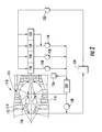
- FIG. 1 depicts an example of a prior art aircraft gas turbine engine 10 with a fuel tank recirculation system.
- the engine 10 has a fan 12, a high pressure compressor 14, a combustor 16, a high pressure turbine 18, and a low pressure turbine 20, all arranged in a serial, axial flow relationship.
- the engine 10 is operable to generate a core flow of exhaust gases as well as a bypass flow in a conventional manner.
- the engine 10 is a low-bypass turbofan in which a portion of the flow from the fan 12 is directed around the core in a bypass duct 22.
- the bypass flow and the core flow both exit into an afterburner duct 24 which has an afterburner flameholder 26 disposed at its upstream end.
- a fuel-to-oil heat exchanger 28 is coupled to the lubrication system 30 of the engine 10.
- a feed pump 32 pumps fuel from the tanks 34 of the aircraft (not shown) through the fuel-to-oil heat exchanger 28 where it absorbs heat from the oil. The fuel then passes downstream where it is metered into the combustor 16 and burned.
- the heat load required to be rejected from the oil is greater than the heat sink capacity of the fuel at the required fuel flow for the engine operating condition. For example, this can occur when the oil is at a high temperature and the fuel flow is low (e.g. flight idle).
- the fuel in the tanks 34 may become very hot and it may become necessary to use ground support equipment to cool the fuel.
- tank fuel temperature increases at an ever increasing rate as the tanks 34 become near empty. Furthermore, this raises the temperature of the fuel as subsequently supplied to the engine 10.
- the engine 10 may have limits on the acceptable input fuel temperature. For example, the fuel may be needed at a relatively low temperature for cooling a full authority digital engine control (FADEC) or other electronics.
- FADEC full authority digital engine control
- the present invention provides a method and apparatus for using fan bleed air to cool oil in a gas turbine engine.
- a heat exchanger system for a gas turbine engine includes: (a) a fan having at least two stages of rotating fan blades surrounded by a fan casing, the fan operable to produce a flow of pressurized air at a fan exit; (b) at least one heat exchanger having a first flowpath in fluid communication with the fan at a location upstream of the fan exit; and (c) a fluid system coupled to a second flowpath of the at least one heat exchanger.
- the first and second flowpaths are thermally coupled to each other.
- a gas turbine engine includes: (a) a fan having at least two stages of rotating fan blades surrounded by a fan casing, the fan operable to produce a flow of pressurized air at a fan exit; (b) a heat exchanger having a first flowpath in fluid communication with the fan upstream of the fan exit; (c) at least one heat source disposed in the engine remote from the heat exchanger; and; (d) a fluid circuit coupled between the at least one heat source and a second flowpath of the heat exchanger, and operable to circulate a working fluid therebetween.
- the first and second flowpaths are thermally coupled within the heat exchanger.
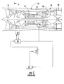
- Figure 2 depicts an exemplary gas turbine engine 110 incorporating a fan bleed heat transfer system constructed in accordance with an aspect of the present invention.
- the basic engine 110 is a low-bypass turbofan configuration substantially similar in construction to the engine 10 described above.
- the fan 112 discharges pressurized air to the downstream compressor at a fan exit 115.
- One or more bleed air heat exchangers 116 are mounted to the fan casing 114 in close proximity to the fan 112.
- the heat exchangers are of the air-to-liquid type and are as described in more detail below.
- Scavenge pumps 118 are provided which remove heated oil from sumps 120 and a gearbox 122 of the engine 110 and pump it to an oil tank 124, after removal of air in an air/oil separator 126. While the sumps 120 and gearbox 122 are commonly found in gas turbine engines, oil or another liquid could also be used to remove heat from any other heat source within the engine 110.
- the hot engine scavenge oil flows from the oil tank 124 to the bleed air heat exchangers 116 where heat is removed from the oil.
- a bypass valve 128 is provided to assure continuous oil flow in the oil system in the event oil congeals in the bleed air heat exchanger 116 (for example, due to exceptionally cold fan bleed air passing through the bleed air heat exchanger 116).
- the fan bleed air is used to cool the engine oil.
- the engine oil may be used directly as the liquid-side working fluid for the fan bleed heat exchangers 116.
- another fluid such as fuel or a water-glycol mixture, may be used as an intermediate medium to transfer heat from the engine oil to the bleed air heat exchanger 116.
- the oil may pass through a conventional oil-to-fuel heat exchanger 130 where, depending on operating conditions, heat is transferred from the oil to the fuel, or from the fuel to the oil.
- the oil is then returned to the sumps 120 and gearbox 122 by a supply pump 132.
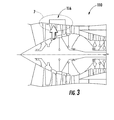
- FIG 3 is a side view of the engine 110 showing the location of the bleed air heat exchanger 116.
- the bleed air heat exchanger 116 is mounted to the exterior of the fan casing 114 and is positioned to receive airflow bled from the fan 112 upstream of the fan exit 115, as shown generally by the large arrow.
- a single bleed air heat exchanger 116 is shown, but it will be understood that a plurality of them could be positioned around the periphery of the fan casing 114.
- FIGS 4-6 illustrate the bleed air heat exchanger 116 in more detail. It is an air-to liquid configuration and has fore and aft plenums 134 and 136 including an inlet 138 and an outlet 140, respectively.
- the plenums 134 and 136 communicate with a series of parallel liquid channels 142, which may include fins 144 (see Figure 5 ) or other heat transfer enhancements.
- the liquid channels 142 are separated by air channels 146 which may also include fins 148 (see Figure 6 ) or other heat transfer enhancements.
- the liquid channels 142 constitute a first flowpath and the air channels 146 constitute a second flowpath.
- the two flowpaths are mutually thermally coupled, that is, they are arranged such that heat energy can flow from one flowpath to the other.
- Figure 7 illustrates the bleed air flow path.
- air discharged from the fan first stage blades 149 passes aft and radially outboard past the outer platforms 150 of the second stage vanes 152, through existing gaps between the periphery of the outer platforms 150 and the fan casing 114.
- a radial gap 154 between the outer platforms 150 and the fan casing 114 allows air flow in a circumferential direction. The air then bleeds through the fan casing 114 through one or more bleed apertures 156.
- the number, shape, size, and position of the bleed apertures 156 may be selected in a known manner to permit adequate mass air flow to the bleed air heat exchanger 116 with an acceptable pressure loss, and to throttle the bleed flow to prevent excessive loss from the fan air flow.
- a plenum 158 may be provided between the fan casing 114 and the bleed air heat exchanger 116 to permit fore-and-aft air flow. Depending on the specific engine and fan configuration it may be possible to bleed air from another stage of the fan 112.
- the air discharge pressure is quite small, and only the static pressure is available for bleed air cooling.
- the available heat exchanger air pressure drop is the blade tip discharge pressure less the pressure drop through the second stage vane outer platforms 150, the bleed apertures 156 and the bleed air heat exchanger 116, minus the fan cowl static pressure outside the bleed air heat exchanger 116 (which is essentially ambient pressure).
- the bleed air heat exchanger 116 uses a large ratio of air frontal face area to air flow depth (i.e. radial thickness).
- a secondary advantage of this configuration is that hot air from the bleed air heat exchanger 116 is directed radially outboard, away from temperature-sensitive components such as electrical cables.
- the total heat sink available in the bleed air and the fuel scheduled for combustion will be equal to or greater than the heat load required to keep the oil at an acceptable temperature. Therefore, no heat will be transferred to the aircraft tanks in the form of heated, recirculated fuel. This includes the most critical operating conditions where combustion fuel flow is low, for example, ground idle, cruise, and flight idle conditions. Furthermore, in some flight conditions, the bleed air heat exchanger 116 not only dissipates heat which would otherwise return to the tanks, it also cools the engine fuel at several flight conditions (negative fuel-oil heat exchanger heat transfer) thus providing lower fuel temperature to the engine fuel nozzles with less likelihood for nozzle fuel coking.
Landscapes
- Engineering & Computer Science (AREA)
- Chemical & Material Sciences (AREA)
- Combustion & Propulsion (AREA)
- Mechanical Engineering (AREA)
- General Engineering & Computer Science (AREA)
- Structures Of Non-Positive Displacement Pumps (AREA)
Abstract
Description
- This invention relates generally to gas turbine engines and methods for oil cooling in such engines.
- Gas turbine engines are commonly provided with a circulating oil system for lubricating and cooling various engine components such as bearings, gearboxes, and the like. In operation the oil absorbs a substantial amount of heat that must be rejected to the environment in order to maintain the oil at acceptable temperatures. Commonly, the oil is circulated through an oil-to-fuel heat exchanger where heat from the oil is rejected to the fuel, which acts as a heat sink. The fuel is subsequently injected into the engine's combustor and burned.
- In many operating conditions, aircraft gas turbine engines have more oil heat load than heat sink from the fuel which will be burnt in the engine. The typical solution to this is to either cool engine fuel or engine oil with engine fan air, or to pump fuel through the oil-to-fuel heat exchanger at a higher rate than required for combustion, with the excess fuel flow being recirculated from the engine back to the aircraft fuel tanks. Low-bypass military turbofan engines have too many fan stages (typically three) to make fan air cooling a viable solution, because the fan duct discharge air is too hot. Therefore, tank recirculation is used.
-
Figure 1 depicts an example of a prior art aircraftgas turbine engine 10 with a fuel tank recirculation system. Theengine 10 has afan 12, ahigh pressure compressor 14, a combustor 16, ahigh pressure turbine 18, and alow pressure turbine 20, all arranged in a serial, axial flow relationship. Theengine 10 is operable to generate a core flow of exhaust gases as well as a bypass flow in a conventional manner. In the illustrated example, theengine 10 is a low-bypass turbofan in which a portion of the flow from thefan 12 is directed around the core in abypass duct 22. The bypass flow and the core flow both exit into anafterburner duct 24 which has anafterburner flameholder 26 disposed at its upstream end. - A fuel-to-
oil heat exchanger 28 is coupled to thelubrication system 30 of theengine 10. Afeed pump 32 pumps fuel from thetanks 34 of the aircraft (not shown) through the fuel-to-oil heat exchanger 28 where it absorbs heat from the oil. The fuel then passes downstream where it is metered into the combustor 16 and burned. In many cases the heat load required to be rejected from the oil is greater than the heat sink capacity of the fuel at the required fuel flow for the engine operating condition. For example, this can occur when the oil is at a high temperature and the fuel flow is low (e.g. flight idle). - Accordingly, to get sufficient cooling, fuel is supplied to the fuel-to-
oil heat exchanger 28 at the required rate for cooling, then the excess above that needed for engine operation is routed back to thetanks 34. - During ground idle the fuel in the
tanks 34 may become very hot and it may become necessary to use ground support equipment to cool the fuel. During flight, tank fuel temperature increases at an ever increasing rate as thetanks 34 become near empty. Furthermore, this raises the temperature of the fuel as subsequently supplied to theengine 10. Theengine 10 may have limits on the acceptable input fuel temperature. For example, the fuel may be needed at a relatively low temperature for cooling a full authority digital engine control (FADEC) or other electronics. - These and other shortcomings of the prior art are addressed by the present invention, which provides a method and apparatus for using fan bleed air to cool oil in a gas turbine engine.
- According to one aspect of the invention, a heat exchanger system for a gas turbine engine includes: (a) a fan having at least two stages of rotating fan blades surrounded by a fan casing, the fan operable to produce a flow of pressurized air at a fan exit; (b) at least one heat exchanger having a first flowpath in fluid communication with the fan at a location upstream of the fan exit; and (c) a fluid system coupled to a second flowpath of the at least one heat exchanger. The first and second flowpaths are thermally coupled to each other.
- According to another aspect of the invention, a gas turbine engine includes: (a) a fan having at least two stages of rotating fan blades surrounded by a fan casing, the fan operable to produce a flow of pressurized air at a fan exit; (b) a heat exchanger having a first flowpath in fluid communication with the fan upstream of the fan exit; (c) at least one heat source disposed in the engine remote from the heat exchanger; and; (d) a fluid circuit coupled between the at least one heat source and a second flowpath of the heat exchanger, and operable to circulate a working fluid therebetween. The first and second flowpaths are thermally coupled within the heat exchanger.
- There follows a detailed description of embodiments of the invention by way of example only with reference to the accompanying drawings, in which:
-
Figure 1 is a schematic view of a gas turbine engine incorporating a prior art heat exchanger system; -
Figure 2 is a schematic view of a gas turbine engine incorporating a heat exchanger system constructed according to an aspect of the present invention; -
Figure 3 is cross-sectional view of a portion of the fan section of the engine shown inFigure 2 , having a heat exchanger mounted thereto; -
Figure 4 is a plan view of the heat exchanger ofFigure 3 ; -
Figure 5 is a view taken along lines 5-5 ofFigure 4 ; -
Figure 6 is a view taken along lines 6-6 ofFigure 4 ; -
Figure 7 is an enlarged view of a portion ofFigure 3 ; and -
Figure 8 is a view taken along lines 8-8 ofFigure 7 . - Referring to the drawings wherein identical reference numerals denote the same elements throughout the various views,
Figure 2 depicts an exemplarygas turbine engine 110 incorporating a fan bleed heat transfer system constructed in accordance with an aspect of the present invention. Thebasic engine 110 is a low-bypass turbofan configuration substantially similar in construction to theengine 10 described above. For illustrative clarity only the three-stage fan 112 and thefan casing 114 are shown in detail. Thefan 112 discharges pressurized air to the downstream compressor at afan exit 115. - One or more bleed
air heat exchangers 116 are mounted to thefan casing 114 in close proximity to thefan 112. The heat exchangers are of the air-to-liquid type and are as described in more detail below.Scavenge pumps 118 are provided which remove heated oil fromsumps 120 and agearbox 122 of theengine 110 and pump it to anoil tank 124, after removal of air in an air/oil separator 126. While thesumps 120 andgearbox 122 are commonly found in gas turbine engines, oil or another liquid could also be used to remove heat from any other heat source within theengine 110. - The hot engine scavenge oil flows from the
oil tank 124 to the bleedair heat exchangers 116 where heat is removed from the oil. Abypass valve 128 is provided to assure continuous oil flow in the oil system in the event oil congeals in the bleed air heat exchanger 116 (for example, due to exceptionally cold fan bleed air passing through the bleed air heat exchanger 116). - The fan bleed air is used to cool the engine oil. As shown in
Figure 2 , the engine oil may be used directly as the liquid-side working fluid for the fan bleedheat exchangers 116. Optionally another fluid, such as fuel or a water-glycol mixture, may be used as an intermediate medium to transfer heat from the engine oil to the bleedair heat exchanger 116. - After exiting the bleed
air heat exchangers 116, the oil may pass through a conventional oil-to-fuel heat exchanger 130 where, depending on operating conditions, heat is transferred from the oil to the fuel, or from the fuel to the oil. The oil is then returned to thesumps 120 andgearbox 122 by asupply pump 132. -
Figure 3 is a side view of theengine 110 showing the location of the bleedair heat exchanger 116. The bleedair heat exchanger 116 is mounted to the exterior of thefan casing 114 and is positioned to receive airflow bled from thefan 112 upstream of thefan exit 115, as shown generally by the large arrow. For illustrative purposes only a single bleedair heat exchanger 116 is shown, but it will be understood that a plurality of them could be positioned around the periphery of thefan casing 114. -
Figures 4-6 illustrate the bleedair heat exchanger 116 in more detail. It is an air-to liquid configuration and has fore andaft plenums inlet 138 and anoutlet 140, respectively. Theplenums liquid channels 142, which may include fins 144 (seeFigure 5 ) or other heat transfer enhancements. Theliquid channels 142 are separated byair channels 146 which may also include fins 148 (seeFigure 6 ) or other heat transfer enhancements. Within the bleedair heat exchanger 116, theliquid channels 142 constitute a first flowpath and theair channels 146 constitute a second flowpath. As with all heat exchangers, the two flowpaths are mutually thermally coupled, that is, they are arranged such that heat energy can flow from one flowpath to the other. -
Figure 7 illustrates the bleed air flow path. As shown by the solid arrows, air discharged from the fanfirst stage blades 149 passes aft and radially outboard past theouter platforms 150 of thesecond stage vanes 152, through existing gaps between the periphery of theouter platforms 150 and thefan casing 114. Aradial gap 154 between theouter platforms 150 and thefan casing 114 allows air flow in a circumferential direction. The air then bleeds through thefan casing 114 through one ormore bleed apertures 156. The number, shape, size, and position of thebleed apertures 156 may be selected in a known manner to permit adequate mass air flow to the bleedair heat exchanger 116 with an acceptable pressure loss, and to throttle the bleed flow to prevent excessive loss from the fan air flow. Aplenum 158 may be provided between thefan casing 114 and the bleedair heat exchanger 116 to permit fore-and-aft air flow. Depending on the specific engine and fan configuration it may be possible to bleed air from another stage of thefan 112. - While the air temperature at the tip of the fan
first stage blades 149 is relatively low and thus suitable for cooling, the air discharge pressure is quite small, and only the static pressure is available for bleed air cooling. The available heat exchanger air pressure drop is the blade tip discharge pressure less the pressure drop through the second stage vaneouter platforms 150, thebleed apertures 156 and the bleedair heat exchanger 116, minus the fan cowl static pressure outside the bleed air heat exchanger 116 (which is essentially ambient pressure). In order to obtain adequate air side heat transfer with this very low pressure drop, the bleedair heat exchanger 116 uses a large ratio of air frontal face area to air flow depth (i.e. radial thickness). A secondary advantage of this configuration is that hot air from the bleedair heat exchanger 116 is directed radially outboard, away from temperature-sensitive components such as electrical cables. - With proper selection of the various components described above the total heat sink available in the bleed air and the fuel scheduled for combustion will be equal to or greater than the heat load required to keep the oil at an acceptable temperature. Therefore, no heat will be transferred to the aircraft tanks in the form of heated, recirculated fuel. This includes the most critical operating conditions where combustion fuel flow is low, for example, ground idle, cruise, and flight idle conditions. Furthermore, in some flight conditions, the bleed
air heat exchanger 116 not only dissipates heat which would otherwise return to the tanks, it also cools the engine fuel at several flight conditions (negative fuel-oil heat exchanger heat transfer) thus providing lower fuel temperature to the engine fuel nozzles with less likelihood for nozzle fuel coking. - The foregoing has described a heat exchanger for a gas turbine engine and a method for its operation. While specific embodiments of the present invention have been described, it will be apparent to those skilled in the art that various modifications thereto can be made without departing from the spirit and scope of the invention. Accordingly, the foregoing description of the preferred embodiment of the invention and the best mode for practicing the invention are provided for the purpose of illustration only.
Claims (12)
- A heat exchanger system for a gas turbine engine comprising:(a) a fan (112) comprising at least two stages of rotating fan blades surrounded by a fan casing (114), the fan (112) operable to produce a flow of pressurized air at a fan exit;(b) at least one heat exchanger (116) having a first flowpath in fluid communication with the fan (112) at a location upstream of the fan exit; and(c) a fluid system coupled to a second flowpath of the at least one heat exchanger (116); wherein the first and second flowpaths are thermally coupled to each other.
- A gas turbine engine (110) comprising:(a) a fan (112) comprising at least two stages of rotating fan blades surrounded by a fan casing (114), the fan (112) operable to produce a flow of pressurized air at a fan exit;(b) a heat exchanger (116) having a first flowpath in fluid communication with the fan (112) upstream of the fan exit;(c) at least one heat source disposed in the engine remote from the heat exchanger (116); and;(d) a fluid circuit coupled between the heat source and a second flowpath of the heat exchanger (116), and operable to circulate a working fluid therebetween, wherein the first and second flowpaths are thermally coupled within the heat exchanger (116).
- The gas turbine engine (110) of claim 2 wherein the heat source is a bearing sump and the working fluid is lubricating oil.
- The gas turbine engine (110) of claim 3 further comprising at least one scavenge pump (118) disposed between the bearing sump and the heat exchanger (116).
- The gas turbine engine (110) of claim 4 further comprising at least one oil tank (124) disposed between the scavenge pump (118) and the heat exchanger (116).
- The gas turbine engine (110) of claim 5 further comprising a bypass valve (128) disposed between the at least one oil tank and the heat exchanger (116).
- The gas turbine engine (110) of claim 3 further comprising at least one supply pump (132) disposed between the heat exchanger (116) and located upstream of the at least one bearing sump.
- The invention of claims 1 or 2 wherein the fan casing (114) includes at least one bleed aperture (156) passing therethrough which communicates with the heat exchanger (116).
- The invention of claim 8 wherein the fan (112) further comprises an annular array of stationary vanes (152) each having a platform disposed at its outer end; and
wherein a radial gap (154) is defined between each of the platforms and the fan casing (114), the bleed apertures (156) being positioned within an axial extent of the radial gap. - The invention of claims 1 or 2 wherein the at least one heat exchanger (116) is mounted to an exterior of the fan casing (114).
- The invention of claim 10 wherein an outer surface of the fan casing (114) has an annular plenum (158) formed therein, the plenum (158) disposed between the fan casing (114) and the heat exchanger (116).
- The invention of claims 1 or 2 wherein the fan (112) comprises three stages of rotating fan blades, and the heat exchanger (116) communicates with the first stage of fan blades.
Applications Claiming Priority (2)
| Application Number | Priority Date | Filing Date | Title |
|---|---|---|---|
| US9155308P | 2008-08-25 | 2008-08-25 | |
| US12/240,359 US8266889B2 (en) | 2008-08-25 | 2008-09-29 | Gas turbine engine fan bleed heat exchanger system |
Publications (3)
| Publication Number | Publication Date |
|---|---|
| EP2159383A2 true EP2159383A2 (en) | 2010-03-03 |
| EP2159383A3 EP2159383A3 (en) | 2013-04-03 |
| EP2159383B1 EP2159383B1 (en) | 2016-04-13 |
Family
ID=40951572
Family Applications (1)
| Application Number | Title | Priority Date | Filing Date |
|---|---|---|---|
| EP09167468.9A Not-in-force EP2159383B1 (en) | 2008-08-25 | 2009-08-07 | Gas turbine engine fan bleed heat exchanger system |
Country Status (5)
| Country | Link |
|---|---|
| US (1) | US8266889B2 (en) |
| EP (1) | EP2159383B1 (en) |
| JP (1) | JP5325706B2 (en) |
| CA (1) | CA2675400C (en) |
| ES (1) | ES2575578T3 (en) |
Cited By (2)
| Publication number | Priority date | Publication date | Assignee | Title |
|---|---|---|---|---|
| BE1026232B1 (en) * | 2018-04-23 | 2019-11-25 | Safran Aero Boosters Sa | HYDRAULIC SYSTEM |
| EP3708808A1 (en) * | 2019-03-12 | 2020-09-16 | Rolls-Royce plc | Fuel manifold cooling |
Families Citing this family (52)
| Publication number | Priority date | Publication date | Assignee | Title |
|---|---|---|---|---|
| US9194294B2 (en) | 2012-05-07 | 2015-11-24 | United Technologies Corporation | Gas turbine engine oil tank |
| US8572943B1 (en) | 2012-05-31 | 2013-11-05 | United Technologies Corporation | Fundamental gear system architecture |
| US20150308351A1 (en) | 2012-05-31 | 2015-10-29 | United Technologies Corporation | Fundamental gear system architecture |
| US9765694B2 (en) | 2012-08-07 | 2017-09-19 | Unison Industries, Llc | Gas turbine engine heat exchangers and methods of assembling the same |
| US10247097B2 (en) | 2012-12-10 | 2019-04-02 | United Technologies Corporation | Gas turbine engine with plural accessory air paths |
| CA2920482A1 (en) * | 2013-08-16 | 2015-02-19 | General Electric Company | Flow vortex spoiler |
| CA2924679C (en) | 2013-09-22 | 2018-07-17 | Unison Industries, Llc | Dual seated by-pass valve for surface coolers |
| CA2854728C (en) * | 2013-09-24 | 2016-08-16 | United Technologies Corporation | Fundamental gear system architecture |
| US9677474B2 (en) | 2013-11-18 | 2017-06-13 | Unison Industries, Llc | Surface cooler support mechanism |
| US10760493B2 (en) | 2013-12-18 | 2020-09-01 | Raytheon Technologies Corporation | Heat exchanger flow control assembly |
| US10006369B2 (en) | 2014-06-30 | 2018-06-26 | General Electric Company | Method and system for radial tubular duct heat exchangers |
| US9777963B2 (en) | 2014-06-30 | 2017-10-03 | General Electric Company | Method and system for radial tubular heat exchangers |
| US10731560B2 (en) | 2015-02-12 | 2020-08-04 | Raytheon Technologies Corporation | Intercooled cooling air |
| US11808210B2 (en) | 2015-02-12 | 2023-11-07 | Rtx Corporation | Intercooled cooling air with heat exchanger packaging |
| US10371055B2 (en) | 2015-02-12 | 2019-08-06 | United Technologies Corporation | Intercooled cooling air using cooling compressor as starter |
| US9835380B2 (en) | 2015-03-13 | 2017-12-05 | General Electric Company | Tube in cross-flow conduit heat exchanger |
| US10830148B2 (en) | 2015-04-24 | 2020-11-10 | Raytheon Technologies Corporation | Intercooled cooling air with dual pass heat exchanger |
| US10221862B2 (en) | 2015-04-24 | 2019-03-05 | United Technologies Corporation | Intercooled cooling air tapped from plural locations |
| US10480419B2 (en) | 2015-04-24 | 2019-11-19 | United Technologies Corporation | Intercooled cooling air with plural heat exchangers |
| US10100739B2 (en) | 2015-05-18 | 2018-10-16 | United Technologies Corporation | Cooled cooling air system for a gas turbine engine |
| US9932905B2 (en) | 2015-06-22 | 2018-04-03 | United Technologies Corporation | Bypass duct heat exchanger with controlled fan |
| US10794288B2 (en) | 2015-07-07 | 2020-10-06 | Raytheon Technologies Corporation | Cooled cooling air system for a turbofan engine |
| CA2936633C (en) | 2015-08-12 | 2021-12-28 | Rolls-Royce North American Technologies, Inc. | Heat exchanger for a gas turbine engine propulsion system |
| US10443508B2 (en) | 2015-12-14 | 2019-10-15 | United Technologies Corporation | Intercooled cooling air with auxiliary compressor control |
| US10151247B2 (en) * | 2016-03-18 | 2018-12-11 | United Technologies Corporation | Heat exchanger suspension system with pipe-to-linkage spring rate ratio |
| US10378835B2 (en) | 2016-03-25 | 2019-08-13 | Unison Industries, Llc | Heat exchanger with non-orthogonal perforations |
| US10260422B2 (en) | 2016-05-06 | 2019-04-16 | United Technologies Corporation | Heat temperature gradient heat exchanger |
| US10451353B2 (en) * | 2016-08-05 | 2019-10-22 | Hamilton Sundstrand Corporation | Aircraft electronics thermal regulation systems |
| US10669940B2 (en) | 2016-09-19 | 2020-06-02 | Raytheon Technologies Corporation | Gas turbine engine with intercooled cooling air and turbine drive |
| US10550768B2 (en) | 2016-11-08 | 2020-02-04 | United Technologies Corporation | Intercooled cooled cooling integrated air cycle machine |
| US10794290B2 (en) | 2016-11-08 | 2020-10-06 | Raytheon Technologies Corporation | Intercooled cooled cooling integrated air cycle machine |
| US10961911B2 (en) | 2017-01-17 | 2021-03-30 | Raytheon Technologies Corporation | Injection cooled cooling air system for a gas turbine engine |
| US10995673B2 (en) | 2017-01-19 | 2021-05-04 | Raytheon Technologies Corporation | Gas turbine engine with intercooled cooling air and dual towershaft accessory gearbox |
| US10577964B2 (en) | 2017-03-31 | 2020-03-03 | United Technologies Corporation | Cooled cooling air for blade air seal through outer chamber |
| US10711640B2 (en) | 2017-04-11 | 2020-07-14 | Raytheon Technologies Corporation | Cooled cooling air to blade outer air seal passing through a static vane |
| EP3450722B1 (en) | 2017-08-31 | 2024-02-14 | General Electric Company | Air delivery system for a gas turbine engine |
| US10738703B2 (en) | 2018-03-22 | 2020-08-11 | Raytheon Technologies Corporation | Intercooled cooling air with combined features |
| US10808619B2 (en) | 2018-04-19 | 2020-10-20 | Raytheon Technologies Corporation | Intercooled cooling air with advanced cooling system |
| US10830145B2 (en) | 2018-04-19 | 2020-11-10 | Raytheon Technologies Corporation | Intercooled cooling air fleet management system |
| US10718233B2 (en) | 2018-06-19 | 2020-07-21 | Raytheon Technologies Corporation | Intercooled cooling air with low temperature bearing compartment air |
| US11255268B2 (en) | 2018-07-31 | 2022-02-22 | Raytheon Technologies Corporation | Intercooled cooling air with selective pressure dump |
| US11077949B2 (en) * | 2018-10-05 | 2021-08-03 | The Boeing Company | Dual turbine thermal management system (TMS) |
| US11300002B2 (en) | 2018-12-07 | 2022-04-12 | Pratt & Whitney Canada Corp. | Static take-off port |
| US11174816B2 (en) | 2019-02-25 | 2021-11-16 | Rolls-Royce Corporation | Bypass duct conformal heat exchanger array |
| US11286881B2 (en) | 2019-10-16 | 2022-03-29 | Rolls-Royce North American Technologies Inc. | Gas turbine engine with reversible heat exchanger |
| JP2022079952A (en) * | 2020-11-17 | 2022-05-27 | 本田技研工業株式会社 | Internal combustion engine for aircraft |
| GB2622214A (en) | 2022-09-06 | 2024-03-13 | Rolls Royce Plc | A thermal management system for an aircraft |
| GB2622209B (en) | 2022-09-06 | 2024-12-04 | Rolls Royce Plc | A thermal management system for an aircraft |
| GB2622215B (en) * | 2022-09-06 | 2024-12-04 | Rolls Royce Plc | A thermal management system for an aircraft |
| GB2622212B (en) | 2022-09-06 | 2024-11-20 | Rolls Royce Plc | A thermal management system for an aircraft |
| US12259194B2 (en) | 2023-07-10 | 2025-03-25 | General Electric Company | Thermal management system |
| US12286930B1 (en) | 2023-12-12 | 2025-04-29 | Rolls-Royce North American Technologies Inc. | Turbine engine fan case with bleed air for tip injection and heat exchanger cooling |
Family Cites Families (41)
| Publication number | Priority date | Publication date | Assignee | Title |
|---|---|---|---|---|
| US3842597A (en) * | 1973-03-16 | 1974-10-22 | Gen Electric | Gas turbine engine with means for reducing the formation and emission of nitrogen oxides |
| US4041697A (en) * | 1975-07-17 | 1977-08-16 | The United States Of America As Represented By The Administrator Of The National Aeronautics And Space Administration | Oil cooling system for a gas turbine engine |
| US4104873A (en) * | 1976-11-29 | 1978-08-08 | The United States Of America As Represented By The Administrator Of The United States National Aeronautics And Space Administration | Fuel delivery system including heat exchanger means |
| US4170873A (en) * | 1977-07-20 | 1979-10-16 | Avco Corporation | Lubrication system |
| US4254618A (en) * | 1977-08-18 | 1981-03-10 | General Electric Company | Cooling air cooler for a gas turbofan engine |
| US4645415A (en) * | 1983-12-23 | 1987-02-24 | United Technologies Corporation | Air cooler for providing buffer air to a bearing compartment |
| US4601202A (en) * | 1983-12-27 | 1986-07-22 | General Electric Company | Gas turbine engine component cooling system |
| GB2194592B (en) * | 1986-08-27 | 1990-07-04 | Rolls Royce Plc | Fluid outlet duct |
| US4782658A (en) * | 1987-05-07 | 1988-11-08 | Rolls-Royce Plc | Deicing of a geared gas turbine engine |
| US4914904A (en) * | 1988-11-09 | 1990-04-10 | Avco Corporation | Oil cooler for fan jet engines |
| US5125597A (en) * | 1990-06-01 | 1992-06-30 | General Electric Company | Gas turbine engine powered aircraft environmental control system and boundary layer bleed with energy recovery system |
| US5123242A (en) * | 1990-07-30 | 1992-06-23 | General Electric Company | Precooling heat exchange arrangement integral with mounting structure fairing of gas turbine engine |
| US5203163A (en) * | 1990-08-01 | 1993-04-20 | General Electric Company | Heat exchange arrangement in a gas turbine engine fan duct for cooling hot bleed air |
| US5137230A (en) * | 1991-06-04 | 1992-08-11 | General Electric Company | Aircraft gas turbine engine bleed air energy recovery apparatus |
| US5269135A (en) * | 1991-10-28 | 1993-12-14 | General Electric Company | Gas turbine engine fan cooled heat exchanger |
| US5305616A (en) * | 1992-03-23 | 1994-04-26 | General Electric Company | Gas turbine engine cooling system |
| US5357742A (en) * | 1993-03-12 | 1994-10-25 | General Electric Company | Turbojet cooling system |
| US5363641A (en) * | 1993-08-06 | 1994-11-15 | United Technologies Corporation | Integrated auxiliary power system |
| US5431533A (en) * | 1993-10-15 | 1995-07-11 | United Technologies Corporation | Active vaned passage casing treatment |
| US5452573A (en) * | 1994-01-31 | 1995-09-26 | United Technologies Corporation | High pressure air source for aircraft and engine requirements |
| US5607284A (en) * | 1994-12-29 | 1997-03-04 | United Technologies Corporation | Baffled passage casing treatment for compressor blades |
| FR2734320B1 (en) * | 1995-05-15 | 1997-07-18 | Aerospatiale | DEVICE FOR TAKING UP AND COOLING HOT AIR AT AN AIRCRAFT ENGINE |
| FR2734319B1 (en) * | 1995-05-15 | 1997-07-18 | Aerospatiale | DEVICE FOR TAKING UP AND COOLING HOT AIR AT AN AIRCRAFT ENGINE |
| US5586859A (en) * | 1995-05-31 | 1996-12-24 | United Technologies Corporation | Flow aligned plenum endwall treatment for compressor blades |
| US6438941B1 (en) * | 2001-04-26 | 2002-08-27 | General Electric Company | Bifurcated splitter for variable bleed flow |
| GB2389174B (en) * | 2002-05-01 | 2005-10-26 | Rolls Royce Plc | Cooling systems |
| US6883302B2 (en) * | 2002-12-20 | 2005-04-26 | General Electric Company | Methods and apparatus for generating gas turbine engine thrust with a pulse detonation thrust augmenter |
| US7631483B2 (en) * | 2003-09-22 | 2009-12-15 | General Electric Company | Method and system for reduction of jet engine noise |
| GB2413366B (en) * | 2004-04-24 | 2006-09-13 | Rolls Royce Plc | Engine. |
| US7140174B2 (en) * | 2004-09-30 | 2006-11-28 | General Electric Company | Methods and apparatus for assembling a gas turbine engine |
| FR2891313A1 (en) * | 2005-09-26 | 2007-03-30 | Airbus France Sas | DOUBLE FLOW TURBOMOTEUR HAVING A PRE-COOLER |
| US7614210B2 (en) * | 2006-02-13 | 2009-11-10 | General Electric Company | Double bypass turbofan |
| GB0607771D0 (en) * | 2006-04-20 | 2006-05-31 | Rolls Royce Plc | A heat exchanger arrangement |
| US7861512B2 (en) * | 2006-08-29 | 2011-01-04 | Pratt & Whitney Canada Corp. | Turbofan bypass duct air cooled fluid cooler installation |
| US7770381B2 (en) * | 2006-12-18 | 2010-08-10 | General Electric Company | Duct burning mixed flow turbofan and method of operation |
| US7748211B2 (en) * | 2006-12-19 | 2010-07-06 | United Technologies Corporation | Vapor cooling of detonation engines |
| US7966831B2 (en) * | 2007-08-28 | 2011-06-28 | General Electric Company | Apparatus and method for suppressing dynamic pressure instability in bleed duct |
| US7946806B2 (en) * | 2007-10-10 | 2011-05-24 | United Technologies Corporation | Gas turbine engine systems and related methods involving heat exchange |
| US8024935B2 (en) * | 2008-11-21 | 2011-09-27 | Honeywell International Inc. | Flush inlet scoop design for aircraft bleed air system |
| US8181443B2 (en) * | 2008-12-10 | 2012-05-22 | Pratt & Whitney Canada Corp. | Heat exchanger to cool turbine air cooling flow |
| US20100242492A1 (en) * | 2009-03-30 | 2010-09-30 | Honeywell International Inc. | Distributed engine control systems and gas turbine engines |
-
2008
- 2008-09-29 US US12/240,359 patent/US8266889B2/en active Active
-
2009
- 2009-08-07 EP EP09167468.9A patent/EP2159383B1/en not_active Not-in-force
- 2009-08-07 ES ES09167468.9T patent/ES2575578T3/en active Active
- 2009-08-13 CA CA2675400A patent/CA2675400C/en active Active
- 2009-08-18 JP JP2009188803A patent/JP5325706B2/en not_active Expired - Fee Related
Cited By (2)
| Publication number | Priority date | Publication date | Assignee | Title |
|---|---|---|---|---|
| BE1026232B1 (en) * | 2018-04-23 | 2019-11-25 | Safran Aero Boosters Sa | HYDRAULIC SYSTEM |
| EP3708808A1 (en) * | 2019-03-12 | 2020-09-16 | Rolls-Royce plc | Fuel manifold cooling |
Also Published As
| Publication number | Publication date |
|---|---|
| US20100043396A1 (en) | 2010-02-25 |
| ES2575578T3 (en) | 2016-06-29 |
| US8266889B2 (en) | 2012-09-18 |
| CA2675400C (en) | 2013-09-24 |
| EP2159383A3 (en) | 2013-04-03 |
| EP2159383B1 (en) | 2016-04-13 |
| JP2010048251A (en) | 2010-03-04 |
| JP5325706B2 (en) | 2013-10-23 |
| CA2675400A1 (en) | 2010-02-25 |
Similar Documents
| Publication | Publication Date | Title |
|---|---|---|
| CA2675400C (en) | Gas turbine engine fan bleed heat exchanger system | |
| US11506131B2 (en) | Thermal management system | |
| CN110753783B (en) | Oil cooling system for gas turbine engine | |
| US10196932B2 (en) | OGV heat exchangers networked in parallel and serial flow | |
| EP3241994B1 (en) | System and method for cooling components of a gas turbine engine | |
| US10989411B2 (en) | Heat exchanger for turbo machine | |
| US20080028763A1 (en) | Thermal management system with thrust recovery for a gas turbine engine fan nacelle assembly | |
| EP3121417B1 (en) | Integral oiltank heat exchanger | |
| EP3090163B1 (en) | Compressor rim thermal management | |
| CN106917684A (en) | Heat management system | |
| EP4269765A2 (en) | Hydrogen-exhaust gas heat exchanger of a turbofan engine | |
| EP3081780A1 (en) | Lubricant circulation system and method of circulating lubricant in a gas turbine engine | |
| US12359621B2 (en) | Thermal management system for a gas turbine engine | |
| US12071896B2 (en) | Air-to-air heat exchanger potential in gas turbine engines | |
| CN119801723A (en) | Thermal management systems for engines | |
| EP2971734B1 (en) | Geared architecture turbofan engine thermal management system and method | |
| US12259194B2 (en) | Thermal management system | |
| US11834995B2 (en) | Air-to-air heat exchanger potential in gas turbine engines | |
| US20250035382A1 (en) | Thermal management system | |
| GB2555379A (en) | Gas turbine engine heat exchanger | |
| CN119933858A (en) | Air-to-air heat exchanger potential in gas turbine engines |
Legal Events
| Date | Code | Title | Description |
|---|---|---|---|
| PUAI | Public reference made under article 153(3) epc to a published international application that has entered the european phase |
Free format text: ORIGINAL CODE: 0009012 |
|
| AK | Designated contracting states |
Kind code of ref document: A2 Designated state(s): AT BE BG CH CY CZ DE DK EE ES FI FR GB GR HR HU IE IS IT LI LT LU LV MC MK MT NL NO PL PT RO SE SI SK SM TR |
|
| PUAL | Search report despatched |
Free format text: ORIGINAL CODE: 0009013 |
|
| AK | Designated contracting states |
Kind code of ref document: A3 Designated state(s): AT BE BG CH CY CZ DE DK EE ES FI FR GB GR HR HU IE IS IT LI LT LU LV MC MK MT NL NO PL PT RO SE SI SK SM TR |
|
| RIC1 | Information provided on ipc code assigned before grant |
Ipc: F02K 3/06 20060101ALI20130227BHEP Ipc: F01D 25/12 20060101AFI20130227BHEP Ipc: F02C 7/224 20060101ALI20130227BHEP Ipc: F02C 7/14 20060101ALI20130227BHEP Ipc: F01D 25/18 20060101ALI20130227BHEP |
|
| 17P | Request for examination filed |
Effective date: 20131004 |
|
| RBV | Designated contracting states (corrected) |
Designated state(s): AT BE BG CH CY CZ DE DK EE ES FI FR GB GR HR HU IE IS IT LI LT LU LV MC MK MT NL NO PL PT RO SE SI SK SM TR |
|
| GRAP | Despatch of communication of intention to grant a patent |
Free format text: ORIGINAL CODE: EPIDOSNIGR1 |
|
| INTG | Intention to grant announced |
Effective date: 20151110 |
|
| GRAS | Grant fee paid |
Free format text: ORIGINAL CODE: EPIDOSNIGR3 |
|
| GRAA | (expected) grant |
Free format text: ORIGINAL CODE: 0009210 |
|
| AK | Designated contracting states |
Kind code of ref document: B1 Designated state(s): AT BE BG CH CY CZ DE DK EE ES FI FR GB GR HR HU IE IS IT LI LT LU LV MC MK MT NL NO PL PT RO SE SI SK SM TR |
|
| REG | Reference to a national code |
Ref country code: GB Ref legal event code: FG4D |
|
| REG | Reference to a national code |
Ref country code: AT Ref legal event code: REF Ref document number: 790402 Country of ref document: AT Kind code of ref document: T Effective date: 20160415 Ref country code: CH Ref legal event code: EP |
|
| REG | Reference to a national code |
Ref country code: IE Ref legal event code: FG4D |
|
| REG | Reference to a national code |
Ref country code: DE Ref legal event code: R096 Ref document number: 602009037681 Country of ref document: DE |
|
| REG | Reference to a national code |
Ref country code: ES Ref legal event code: FG2A Ref document number: 2575578 Country of ref document: ES Kind code of ref document: T3 Effective date: 20160629 |
|
| REG | Reference to a national code |
Ref country code: SE Ref legal event code: TRGR |
|
| REG | Reference to a national code |
Ref country code: LT Ref legal event code: MG4D |
|
| REG | Reference to a national code |
Ref country code: FR Ref legal event code: PLFP Year of fee payment: 8 |
|
| REG | Reference to a national code |
Ref country code: AT Ref legal event code: MK05 Ref document number: 790402 Country of ref document: AT Kind code of ref document: T Effective date: 20160413 |
|
| REG | Reference to a national code |
Ref country code: NL Ref legal event code: MP Effective date: 20160413 |
|
| PG25 | Lapsed in a contracting state [announced via postgrant information from national office to epo] |
Ref country code: NO Free format text: LAPSE BECAUSE OF FAILURE TO SUBMIT A TRANSLATION OF THE DESCRIPTION OR TO PAY THE FEE WITHIN THE PRESCRIBED TIME-LIMIT Effective date: 20160713 Ref country code: FI Free format text: LAPSE BECAUSE OF FAILURE TO SUBMIT A TRANSLATION OF THE DESCRIPTION OR TO PAY THE FEE WITHIN THE PRESCRIBED TIME-LIMIT Effective date: 20160413 Ref country code: NL Free format text: LAPSE BECAUSE OF FAILURE TO SUBMIT A TRANSLATION OF THE DESCRIPTION OR TO PAY THE FEE WITHIN THE PRESCRIBED TIME-LIMIT Effective date: 20160413 Ref country code: PL Free format text: LAPSE BECAUSE OF FAILURE TO SUBMIT A TRANSLATION OF THE DESCRIPTION OR TO PAY THE FEE WITHIN THE PRESCRIBED TIME-LIMIT Effective date: 20160413 Ref country code: LT Free format text: LAPSE BECAUSE OF FAILURE TO SUBMIT A TRANSLATION OF THE DESCRIPTION OR TO PAY THE FEE WITHIN THE PRESCRIBED TIME-LIMIT Effective date: 20160413 |
|
| PG25 | Lapsed in a contracting state [announced via postgrant information from national office to epo] |
Ref country code: GR Free format text: LAPSE BECAUSE OF FAILURE TO SUBMIT A TRANSLATION OF THE DESCRIPTION OR TO PAY THE FEE WITHIN THE PRESCRIBED TIME-LIMIT Effective date: 20160714 Ref country code: PT Free format text: LAPSE BECAUSE OF FAILURE TO SUBMIT A TRANSLATION OF THE DESCRIPTION OR TO PAY THE FEE WITHIN THE PRESCRIBED TIME-LIMIT Effective date: 20160816 Ref country code: LV Free format text: LAPSE BECAUSE OF FAILURE TO SUBMIT A TRANSLATION OF THE DESCRIPTION OR TO PAY THE FEE WITHIN THE PRESCRIBED TIME-LIMIT Effective date: 20160413 Ref country code: HR Free format text: LAPSE BECAUSE OF FAILURE TO SUBMIT A TRANSLATION OF THE DESCRIPTION OR TO PAY THE FEE WITHIN THE PRESCRIBED TIME-LIMIT Effective date: 20160413 Ref country code: AT Free format text: LAPSE BECAUSE OF FAILURE TO SUBMIT A TRANSLATION OF THE DESCRIPTION OR TO PAY THE FEE WITHIN THE PRESCRIBED TIME-LIMIT Effective date: 20160413 |
|
| PG25 | Lapsed in a contracting state [announced via postgrant information from national office to epo] |
Ref country code: BE Free format text: LAPSE BECAUSE OF FAILURE TO SUBMIT A TRANSLATION OF THE DESCRIPTION OR TO PAY THE FEE WITHIN THE PRESCRIBED TIME-LIMIT Effective date: 20160413 Ref country code: IT Free format text: LAPSE BECAUSE OF FAILURE TO SUBMIT A TRANSLATION OF THE DESCRIPTION OR TO PAY THE FEE WITHIN THE PRESCRIBED TIME-LIMIT Effective date: 20160413 |
|
| REG | Reference to a national code |
Ref country code: DE Ref legal event code: R097 Ref document number: 602009037681 Country of ref document: DE |
|
| PG25 | Lapsed in a contracting state [announced via postgrant information from national office to epo] |
Ref country code: DK Free format text: LAPSE BECAUSE OF FAILURE TO SUBMIT A TRANSLATION OF THE DESCRIPTION OR TO PAY THE FEE WITHIN THE PRESCRIBED TIME-LIMIT Effective date: 20160413 Ref country code: EE Free format text: LAPSE BECAUSE OF FAILURE TO SUBMIT A TRANSLATION OF THE DESCRIPTION OR TO PAY THE FEE WITHIN THE PRESCRIBED TIME-LIMIT Effective date: 20160413 Ref country code: SK Free format text: LAPSE BECAUSE OF FAILURE TO SUBMIT A TRANSLATION OF THE DESCRIPTION OR TO PAY THE FEE WITHIN THE PRESCRIBED TIME-LIMIT Effective date: 20160413 Ref country code: CZ Free format text: LAPSE BECAUSE OF FAILURE TO SUBMIT A TRANSLATION OF THE DESCRIPTION OR TO PAY THE FEE WITHIN THE PRESCRIBED TIME-LIMIT Effective date: 20160413 Ref country code: RO Free format text: LAPSE BECAUSE OF FAILURE TO SUBMIT A TRANSLATION OF THE DESCRIPTION OR TO PAY THE FEE WITHIN THE PRESCRIBED TIME-LIMIT Effective date: 20160413 |
|
| PLBE | No opposition filed within time limit |
Free format text: ORIGINAL CODE: 0009261 |
|
| STAA | Information on the status of an ep patent application or granted ep patent |
Free format text: STATUS: NO OPPOSITION FILED WITHIN TIME LIMIT |
|
| PG25 | Lapsed in a contracting state [announced via postgrant information from national office to epo] |
Ref country code: SM Free format text: LAPSE BECAUSE OF FAILURE TO SUBMIT A TRANSLATION OF THE DESCRIPTION OR TO PAY THE FEE WITHIN THE PRESCRIBED TIME-LIMIT Effective date: 20160413 |
|
| 26N | No opposition filed |
Effective date: 20170116 |
|
| PG25 | Lapsed in a contracting state [announced via postgrant information from national office to epo] |
Ref country code: MC Free format text: LAPSE BECAUSE OF FAILURE TO SUBMIT A TRANSLATION OF THE DESCRIPTION OR TO PAY THE FEE WITHIN THE PRESCRIBED TIME-LIMIT Effective date: 20160413 |
|
| REG | Reference to a national code |
Ref country code: CH Ref legal event code: PL |
|
| PG25 | Lapsed in a contracting state [announced via postgrant information from national office to epo] |
Ref country code: CH Free format text: LAPSE BECAUSE OF NON-PAYMENT OF DUE FEES Effective date: 20160831 Ref country code: LI Free format text: LAPSE BECAUSE OF NON-PAYMENT OF DUE FEES Effective date: 20160831 |
|
| PG25 | Lapsed in a contracting state [announced via postgrant information from national office to epo] |
Ref country code: SI Free format text: LAPSE BECAUSE OF FAILURE TO SUBMIT A TRANSLATION OF THE DESCRIPTION OR TO PAY THE FEE WITHIN THE PRESCRIBED TIME-LIMIT Effective date: 20160413 |
|
| REG | Reference to a national code |
Ref country code: IE Ref legal event code: MM4A |
|
| PG25 | Lapsed in a contracting state [announced via postgrant information from national office to epo] |
Ref country code: IE Free format text: LAPSE BECAUSE OF NON-PAYMENT OF DUE FEES Effective date: 20160807 |
|
| REG | Reference to a national code |
Ref country code: FR Ref legal event code: PLFP Year of fee payment: 9 |
|
| PG25 | Lapsed in a contracting state [announced via postgrant information from national office to epo] |
Ref country code: LU Free format text: LAPSE BECAUSE OF NON-PAYMENT OF DUE FEES Effective date: 20160807 |
|
| PGFP | Annual fee paid to national office [announced via postgrant information from national office to epo] |
Ref country code: FR Payment date: 20170825 Year of fee payment: 9 Ref country code: ES Payment date: 20170901 Year of fee payment: 9 Ref country code: GB Payment date: 20170829 Year of fee payment: 9 Ref country code: DE Payment date: 20170829 Year of fee payment: 9 |
|
| PGFP | Annual fee paid to national office [announced via postgrant information from national office to epo] |
Ref country code: SE Payment date: 20170829 Year of fee payment: 9 |
|
| PG25 | Lapsed in a contracting state [announced via postgrant information from national office to epo] |
Ref country code: HU Free format text: LAPSE BECAUSE OF FAILURE TO SUBMIT A TRANSLATION OF THE DESCRIPTION OR TO PAY THE FEE WITHIN THE PRESCRIBED TIME-LIMIT; INVALID AB INITIO Effective date: 20090807 Ref country code: CY Free format text: LAPSE BECAUSE OF FAILURE TO SUBMIT A TRANSLATION OF THE DESCRIPTION OR TO PAY THE FEE WITHIN THE PRESCRIBED TIME-LIMIT Effective date: 20160413 |
|
| PG25 | Lapsed in a contracting state [announced via postgrant information from national office to epo] |
Ref country code: IS Free format text: LAPSE BECAUSE OF FAILURE TO SUBMIT A TRANSLATION OF THE DESCRIPTION OR TO PAY THE FEE WITHIN THE PRESCRIBED TIME-LIMIT Effective date: 20160413 Ref country code: MT Free format text: LAPSE BECAUSE OF NON-PAYMENT OF DUE FEES Effective date: 20160831 Ref country code: MK Free format text: LAPSE BECAUSE OF FAILURE TO SUBMIT A TRANSLATION OF THE DESCRIPTION OR TO PAY THE FEE WITHIN THE PRESCRIBED TIME-LIMIT Effective date: 20160413 Ref country code: TR Free format text: LAPSE BECAUSE OF FAILURE TO SUBMIT A TRANSLATION OF THE DESCRIPTION OR TO PAY THE FEE WITHIN THE PRESCRIBED TIME-LIMIT Effective date: 20160413 |
|
| PG25 | Lapsed in a contracting state [announced via postgrant information from national office to epo] |
Ref country code: BG Free format text: LAPSE BECAUSE OF FAILURE TO SUBMIT A TRANSLATION OF THE DESCRIPTION OR TO PAY THE FEE WITHIN THE PRESCRIBED TIME-LIMIT Effective date: 20160413 |
|
| REG | Reference to a national code |
Ref country code: DE Ref legal event code: R119 Ref document number: 602009037681 Country of ref document: DE |
|
| REG | Reference to a national code |
Ref country code: SE Ref legal event code: EUG |
|
| GBPC | Gb: european patent ceased through non-payment of renewal fee |
Effective date: 20180807 |
|
| PG25 | Lapsed in a contracting state [announced via postgrant information from national office to epo] |
Ref country code: SE Free format text: LAPSE BECAUSE OF NON-PAYMENT OF DUE FEES Effective date: 20180808 |
|
| PG25 | Lapsed in a contracting state [announced via postgrant information from national office to epo] |
Ref country code: DE Free format text: LAPSE BECAUSE OF NON-PAYMENT OF DUE FEES Effective date: 20190301 |
|
| PG25 | Lapsed in a contracting state [announced via postgrant information from national office to epo] |
Ref country code: FR Free format text: LAPSE BECAUSE OF NON-PAYMENT OF DUE FEES Effective date: 20180831 |
|
| REG | Reference to a national code |
Ref country code: ES Ref legal event code: FD2A Effective date: 20190918 |
|
| PG25 | Lapsed in a contracting state [announced via postgrant information from national office to epo] |
Ref country code: GB Free format text: LAPSE BECAUSE OF NON-PAYMENT OF DUE FEES Effective date: 20180807 Ref country code: ES Free format text: LAPSE BECAUSE OF NON-PAYMENT OF DUE FEES Effective date: 20180808 |