EP2158996A1 - A method of joining articles - Google Patents
A method of joining articles Download PDFInfo
- Publication number
- EP2158996A1 EP2158996A1 EP09251805A EP09251805A EP2158996A1 EP 2158996 A1 EP2158996 A1 EP 2158996A1 EP 09251805 A EP09251805 A EP 09251805A EP 09251805 A EP09251805 A EP 09251805A EP 2158996 A1 EP2158996 A1 EP 2158996A1
- Authority
- EP
- European Patent Office
- Prior art keywords
- article
- skin
- joining
- flange
- adjustment
- Prior art date
- Legal status (The legal status is an assumption and is not a legal conclusion. Google has not performed a legal analysis and makes no representation as to the accuracy of the status listed.)
- Withdrawn
Links
Images


Classifications
-
- B—PERFORMING OPERATIONS; TRANSPORTING
- B23—MACHINE TOOLS; METAL-WORKING NOT OTHERWISE PROVIDED FOR
- B23K—SOLDERING OR UNSOLDERING; WELDING; CLADDING OR PLATING BY SOLDERING OR WELDING; CUTTING BY APPLYING HEAT LOCALLY, e.g. FLAME CUTTING; WORKING BY LASER BEAM
- B23K15/00—Electron-beam welding or cutting
- B23K15/0006—Electron-beam welding or cutting specially adapted for particular articles or work
-
- B—PERFORMING OPERATIONS; TRANSPORTING
- B23—MACHINE TOOLS; METAL-WORKING NOT OTHERWISE PROVIDED FOR
- B23K—SOLDERING OR UNSOLDERING; WELDING; CLADDING OR PLATING BY SOLDERING OR WELDING; CUTTING BY APPLYING HEAT LOCALLY, e.g. FLAME CUTTING; WORKING BY LASER BEAM
- B23K15/00—Electron-beam welding or cutting
- B23K15/0033—Preliminary treatment
-
- B—PERFORMING OPERATIONS; TRANSPORTING
- B23—MACHINE TOOLS; METAL-WORKING NOT OTHERWISE PROVIDED FOR
- B23K—SOLDERING OR UNSOLDERING; WELDING; CLADDING OR PLATING BY SOLDERING OR WELDING; CUTTING BY APPLYING HEAT LOCALLY, e.g. FLAME CUTTING; WORKING BY LASER BEAM
- B23K15/00—Electron-beam welding or cutting
- B23K15/04—Electron-beam welding or cutting for welding annular seams
-
- B—PERFORMING OPERATIONS; TRANSPORTING
- B23—MACHINE TOOLS; METAL-WORKING NOT OTHERWISE PROVIDED FOR
- B23K—SOLDERING OR UNSOLDERING; WELDING; CLADDING OR PLATING BY SOLDERING OR WELDING; CUTTING BY APPLYING HEAT LOCALLY, e.g. FLAME CUTTING; WORKING BY LASER BEAM
- B23K31/00—Processes relevant to this subclass, specially adapted for particular articles or purposes, but not covered by any single one of main groups B23K1/00 - B23K28/00
- B23K31/02—Processes relevant to this subclass, specially adapted for particular articles or purposes, but not covered by any single one of main groups B23K1/00 - B23K28/00 relating to soldering or welding
- B23K31/027—Making tubes by soldering or welding
-
- F—MECHANICAL ENGINEERING; LIGHTING; HEATING; WEAPONS; BLASTING
- F01—MACHINES OR ENGINES IN GENERAL; ENGINE PLANTS IN GENERAL; STEAM ENGINES
- F01D—NON-POSITIVE DISPLACEMENT MACHINES OR ENGINES, e.g. STEAM TURBINES
- F01D25/00—Component parts, details, or accessories, not provided for in, or of interest apart from, other groups
- F01D25/24—Casings; Casing parts, e.g. diaphragms, casing fastenings
- F01D25/243—Flange connections; Bolting arrangements
-
- B—PERFORMING OPERATIONS; TRANSPORTING
- B23—MACHINE TOOLS; METAL-WORKING NOT OTHERWISE PROVIDED FOR
- B23K—SOLDERING OR UNSOLDERING; WELDING; CLADDING OR PLATING BY SOLDERING OR WELDING; CUTTING BY APPLYING HEAT LOCALLY, e.g. FLAME CUTTING; WORKING BY LASER BEAM
- B23K2101/00—Articles made by soldering, welding or cutting
- B23K2101/001—Turbines
-
- B—PERFORMING OPERATIONS; TRANSPORTING
- B23—MACHINE TOOLS; METAL-WORKING NOT OTHERWISE PROVIDED FOR
- B23K—SOLDERING OR UNSOLDERING; WELDING; CLADDING OR PLATING BY SOLDERING OR WELDING; CUTTING BY APPLYING HEAT LOCALLY, e.g. FLAME CUTTING; WORKING BY LASER BEAM
- B23K2101/00—Articles made by soldering, welding or cutting
- B23K2101/04—Tubular or hollow articles
- B23K2101/12—Vessels
-
- F—MECHANICAL ENGINEERING; LIGHTING; HEATING; WEAPONS; BLASTING
- F05—INDEXING SCHEMES RELATING TO ENGINES OR PUMPS IN VARIOUS SUBCLASSES OF CLASSES F01-F04
- F05D—INDEXING SCHEME FOR ASPECTS RELATING TO NON-POSITIVE-DISPLACEMENT MACHINES OR ENGINES, GAS-TURBINES OR JET-PROPULSION PLANTS
- F05D2230/00—Manufacture
- F05D2230/20—Manufacture essentially without removing material
- F05D2230/23—Manufacture essentially without removing material by permanently joining parts together
- F05D2230/232—Manufacture essentially without removing material by permanently joining parts together by welding
- F05D2230/233—Electron beam welding
-
- F—MECHANICAL ENGINEERING; LIGHTING; HEATING; WEAPONS; BLASTING
- F05—INDEXING SCHEMES RELATING TO ENGINES OR PUMPS IN VARIOUS SUBCLASSES OF CLASSES F01-F04
- F05D—INDEXING SCHEME FOR ASPECTS RELATING TO NON-POSITIVE-DISPLACEMENT MACHINES OR ENGINES, GAS-TURBINES OR JET-PROPULSION PLANTS
- F05D2260/00—Function
- F05D2260/30—Retaining components in desired mutual position
-
- Y—GENERAL TAGGING OF NEW TECHNOLOGICAL DEVELOPMENTS; GENERAL TAGGING OF CROSS-SECTIONAL TECHNOLOGIES SPANNING OVER SEVERAL SECTIONS OF THE IPC; TECHNICAL SUBJECTS COVERED BY FORMER USPC CROSS-REFERENCE ART COLLECTIONS [XRACs] AND DIGESTS
- Y10—TECHNICAL SUBJECTS COVERED BY FORMER USPC
- Y10T—TECHNICAL SUBJECTS COVERED BY FORMER US CLASSIFICATION
- Y10T29/00—Metal working
- Y10T29/49—Method of mechanical manufacture
- Y10T29/4981—Utilizing transitory attached element or associated separate material
-
- Y—GENERAL TAGGING OF NEW TECHNOLOGICAL DEVELOPMENTS; GENERAL TAGGING OF CROSS-SECTIONAL TECHNOLOGIES SPANNING OVER SEVERAL SECTIONS OF THE IPC; TECHNICAL SUBJECTS COVERED BY FORMER USPC CROSS-REFERENCE ART COLLECTIONS [XRACs] AND DIGESTS
- Y10—TECHNICAL SUBJECTS COVERED BY FORMER USPC
- Y10T—TECHNICAL SUBJECTS COVERED BY FORMER US CLASSIFICATION
- Y10T29/00—Metal working
- Y10T29/49—Method of mechanical manufacture
- Y10T29/49826—Assembling or joining
- Y10T29/49908—Joining by deforming
- Y10T29/49925—Inward deformation of aperture or hollow body wall
-
- Y—GENERAL TAGGING OF NEW TECHNOLOGICAL DEVELOPMENTS; GENERAL TAGGING OF CROSS-SECTIONAL TECHNOLOGIES SPANNING OVER SEVERAL SECTIONS OF THE IPC; TECHNICAL SUBJECTS COVERED BY FORMER USPC CROSS-REFERENCE ART COLLECTIONS [XRACs] AND DIGESTS
- Y10—TECHNICAL SUBJECTS COVERED BY FORMER USPC
- Y10T—TECHNICAL SUBJECTS COVERED BY FORMER US CLASSIFICATION
- Y10T29/00—Metal working
- Y10T29/49—Method of mechanical manufacture
- Y10T29/49826—Assembling or joining
- Y10T29/49947—Assembling or joining by applying separate fastener
- Y10T29/49966—Assembling or joining by applying separate fastener with supplemental joining
- Y10T29/49968—Metal fusion joining
Definitions
- the step of forming the first article includes welding the sheet or sheets to secure the first article in its cylindrical or conical form.
- the method further comprises the step of defining the adjustment features in the first component.
- the adjustment features may be defined by mechanical, laser or water cutting of the first article.
- the attachment features may be defined along a weld join.
- the method further comprises the step of applying a removable adjustment tool to the first article, the adjustment tool being operable to change the length of the adjustment features.
- the step of joining the first article to the second article may comprise welding.
- the step of removing the scrap portion may comprise mechanical, laser or water cutting of the first article.
- the method further comprises the step of joining the first article to a third article along an edge formed when the scrap portion is removed.
- a casing for a turbine engine comprising a skin joined to a flange according to a method defined in any one of the preceding claims.
- Figure 1 depicts a simple cylindrical casing formed in accordance with the invention.
- the nozzle comprises a first flange 2, a second flange 4 and a side wall 6 connecting the two flanges.
- the first flange 2 extends about an axis 8 and in this first embodiment the side wall or skin 6 extends about this axis at a constant radius.
- the skin 6 is formed and welded to the first flange 2 before undergoing a machining step to form a second face to which the second flange 4 is secured.
- the flange 2 has a circumferential length of around 1 metre or more, with some being 2, 3 or 4 or more metres in length.
- flange flange
- skin flange
- flange flange
- flange skin and flange
- joining method typically electron beam welding though other appropriate joining methods may be used.
- the skin 6 is provided with adjustment features 10 to simplify the alignment of a first edge 12 with the first flange 2.
- this edge 12 is shown as being straight to align to the circular flange 2 it is possible to give it a profile to enable the edge, when the skin is formed into a cylinder, to be joined directly to the outside of another cylindrical component such as an engine casing for example.
- the skin 6 may be formed from a single sheet of metal as shown in Figure 2 .
- the sheet has a length that is slightly greater than the diameter of the flange 2 and is bent such that the ends 14 contact one another and are welded together to form a cylinder.
- a series of springs 10 are subsequently produced by machining the cylinder.
- the springs can be formed using any appropriate machining technique e.g. stamping, laser cutting, water-jet cutting or other similar process.
- the sprung region 6"' is, in this figure, shown to be midway round the cylinder from the weld join along edges 14 but this need not be the case and in some embodiments it may be preferable, possibly for stress reasons, to locate the sprung region further round the circumference.
- the skin portions 6, 6'' are originally manufactured separately and welded together along their two opposing edges to form the cylinder.
- the spring features are preferably formed along one of the weld lines.
- the finished cylinder is depicted in Figure 3 .
- the skins 6', 6" are provided with apertures 16 which permit connection of a tool that can adjust the length of the gap 18 either inwards or outwards.
- the surface 12 of the cylinder is presented to the first flange 2 and the circumference length adjusted till it is the correct size for the flange. Once they match the cylinder is welded to the flange.
- the width of gap 18 is typically constant along the length of the cylinder. Where the skin is intended to taper either towards or away from the axis 8 it is usual to require the adjustment of the width of the gap to be different along the length of the column.
- the taper or splay angle of the skin is primarily determined by the profile of the edge 12 presented to the flange 2. If, in its blank form, the edge is concave then generally the skin will splay; if the edge is convex then generally the skin will taper.
- the desired profile of edge 12 is calculated through modelling or measured from an empirical model.
- the springs 10 are curved ligaments that have different lengths the further from the edge 12 each ligament is. The increased lengths permit greater or lesser travel which can help to achieve the correct skin profile.
- the apertures 16 are arranged in pairs and the spacing of each pair can be controlled by the adjustment tool till the correct profile is met. Depending on the requirements, the pair spacings may be controlled individually or en masse.
- the springs retain the conical or cylindrical shape of the skin yet permit the required adjustment in circumferential length which would be impeded if the skin were uniform over the whole of its circumference.
- the springs two alternatives are shown, have a single connection point 20 to each panel portion 6', 6'' and a branched ligature extending between the connection points.
- the branched springs it is possible to reduce any axial twist of the cylinder or cone that is generated as the circumferential length of the skin is adjusted, or by the natural spring of the skin 6.
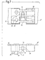
- Figure 7 depicts an exemplary tool for expanding or contracting the gap between the edges of the skin.
- the tool comprises a clamp with a captive nut.
- the tool comprises a first attachment feature attached to skin portion 6' and a second attachment feature attached to skin portion 6''. Both attachment features are secured to their respective skin by bolts 24.
- the bolts 24 are equipped with a lever 26 that allows the bolts to be rotated to lock the attachment features into place. For clarity, only one bolt 24 is shown in the views of the tool in Figure 7 .
- the attachment features are secured together by a threaded bolt 28 and two guide bars 22.
- the guide bars are arranged to slide within slots and serve to aid prevention of twisting of the skins.
- Movement of the two attachment features and hence the two skins relative to each other is achieved by a threaded bolt 28 attached to a nut such that rotation of the nut causes rotation of the threaded bolt and a corresponding translational movement of the attachment features.
- the invention utilises a portion of an article to manage the weld join alignment.
- the portion of the article having the adjustment features is removed from the finished article.
- the invention advantageously allows the article, which may be conical, to be adjusted to fit a second article and enables the joint to achieve what are often tight tolerances demanded in the aerospace industry.
- the invention provides a simple and reliable solution to a very difficult manufacturing problem by providing an adjustable fit for a skin to flange weld where both parts can have 3 dimensional curvatures.
- the method of the invention permits the accommodation of manufacturing variations to facilitate conformance and right-first-time production.
Landscapes
- Engineering & Computer Science (AREA)
- Mechanical Engineering (AREA)
- General Engineering & Computer Science (AREA)
- Laser Beam Processing (AREA)
Abstract
A method of joining a first article (6) to a second article (6) using adjustment features (10) located in an assigned scrap portion (6''') of the first article. The first article (6) can be a casing for a turbine engine the first article being the casing skin and the second article a flange (2,4). The adjustment features (10) are springs that can be stretched to increase the circumference of the skin. Following the correct sizing of the skin and joining to the flange the attachment features are removed along with the assigned scrap portion of the skin.

Description
- This invention relates to a method of joining a first article to a second article. It finds particular application where at least one of the articles is formed from a large sheet and the join has a complex join profile.
- It is an object of the present invention to provide an improved method of joining a first article to a second article.
- According to a first aspect of the invention there is provided a method of joining a first article to a second article, the first article having an assigned scrap portion and adjustment features located in the assigned scrap portion for adjusting dimensions of the first article;
the method having the steps of presenting the first article to the second article, adjusting the dimensions of the first article using the adjustment means, joining the first article to the second article and removing the scrap portion. - Preferably the method includes the step of forming the first article from a sheet or sheets of material curved into a cylindrical or conical form. The first article may also be provided by a machined forging or casting.
- Preferably the step of forming the first article includes welding the sheet or sheets to secure the first article in its cylindrical or conical form.
- Preferably the method further comprises the step of defining the adjustment features in the first component.
- The adjustment features may be defined by mechanical, laser or water cutting of the first article.
- The attachment features may be defined along a weld join.
- Preferably the method further comprises the step of applying a removable adjustment tool to the first article, the adjustment tool being operable to change the length of the adjustment features.
- The step of joining the first article to the second article may comprise welding.
- The step of removing the scrap portion may comprise mechanical, laser or water cutting of the first article.
- Preferably the method further comprises the step of joining the first article to a third article along an edge formed when the scrap portion is removed.
- According to a second aspect of the invention there is provided a casing for a turbine engine comprising a skin joined to a flange according to a method defined in any one of the preceding claims.
- Embodiments of the invention will now be described by way of example only, with reference to the accompanying drawings, in which:
-
Fig. 1 depicts a cylindrical casing having an inlet plane and an outlet plane arranged at a different angle to the inlet plane; -
Fig. 2 depicts a sheet metal blank that may be used to form the cylindrical casing ofFig. 1 ; -
Fig. 3 depicts a cylinder formed from the blank ofFig. 2 ; -
Fig. 4 shows a closer view of the adjustment features of the blank ofFig. 2 ; -
Fig. 5 and Fig. 6 show alternative adjustment features; -
Fig. 7 shows an exemplary tool used to adjust the adjustment features. -
Figure 1 depicts a simple cylindrical casing formed in accordance with the invention. The nozzle comprises afirst flange 2, asecond flange 4 and aside wall 6 connecting the two flanges. - The
first flange 2 extends about an axis 8 and in this first embodiment the side wall orskin 6 extends about this axis at a constant radius. This is a simpler embodiment to manufacture than some embodiments of the invention where the skin is conical i.e. the radius of the skin from the axis increases or decreases as the distance along the axis from the plane of thefirst flange 2 increases. - The
skin 6 is formed and welded to thefirst flange 2 before undergoing a machining step to form a second face to which thesecond flange 4 is secured. In some aircraft casings theflange 2 has a circumferential length of around 1 metre or more, with some being 2, 3 or 4 or more metres in length. - With the size and tight tolerances demanded of these components it is exceptionally difficult to manufacture. Each of the components: flange, skin and flange have a manufacturing tolerance as does the joining method used, which is typically electron beam welding though other appropriate joining methods may be used.
- To facilitate manufacture the
skin 6 is provided withadjustment features 10 to simplify the alignment of afirst edge 12 with thefirst flange 2. Although thisedge 12 is shown as being straight to align to thecircular flange 2 it is possible to give it a profile to enable the edge, when the skin is formed into a cylinder, to be joined directly to the outside of another cylindrical component such as an engine casing for example. - The
skin 6 may be formed from a single sheet of metal as shown inFigure 2 . The sheet has a length that is slightly greater than the diameter of theflange 2 and is bent such that theends 14 contact one another and are welded together to form a cylinder. In theregion 6"' a series ofsprings 10 are subsequently produced by machining the cylinder. The springs can be formed using any appropriate machining technique e.g. stamping, laser cutting, water-jet cutting or other similar process. - The
sprung region 6"' is, in this figure, shown to be midway round the cylinder from the weld join alongedges 14 but this need not be the case and in some embodiments it may be preferable, possibly for stress reasons, to locate the sprung region further round the circumference. - In an alternative manufacturing approach the
skin portions 6, 6'' are originally manufactured separately and welded together along their two opposing edges to form the cylinder. The spring features are preferably formed along one of the weld lines. The finished cylinder is depicted inFigure 3 . - As shown in
Figure 4 , theskins 6', 6" are provided withapertures 16 which permit connection of a tool that can adjust the length of thegap 18 either inwards or outwards. - The
surface 12 of the cylinder is presented to thefirst flange 2 and the circumference length adjusted till it is the correct size for the flange. Once they match the cylinder is welded to the flange. Where a cylindrical skin is desired the width ofgap 18 is typically constant along the length of the cylinder. Where the skin is intended to taper either towards or away from the axis 8 it is usual to require the adjustment of the width of the gap to be different along the length of the column. - The taper or splay angle of the skin is primarily determined by the profile of the
edge 12 presented to theflange 2. If, in its blank form, the edge is concave then generally the skin will splay; if the edge is convex then generally the skin will taper. The desired profile ofedge 12 is calculated through modelling or measured from an empirical model. - Different spring types and arrangements may be used as shown in
Figures 4 to 6 . InFigure 4 thesprings 10 are curved ligaments that have different lengths the further from theedge 12 each ligament is. The increased lengths permit greater or lesser travel which can help to achieve the correct skin profile. Theapertures 16 are arranged in pairs and the spacing of each pair can be controlled by the adjustment tool till the correct profile is met. Depending on the requirements, the pair spacings may be controlled individually or en masse. The springs retain the conical or cylindrical shape of the skin yet permit the required adjustment in circumferential length which would be impeded if the skin were uniform over the whole of its circumference. - In
Figure 5 the springs, two alternatives are shown, have asingle connection point 20 to each panel portion 6', 6'' and a branched ligature extending between the connection points. By using the branched springs it is possible to reduce any axial twist of the cylinder or cone that is generated as the circumferential length of the skin is adjusted, or by the natural spring of theskin 6. - In
Figure 6 , again the springs are curved ligaments but, when compared withFigure 4 , the curve direction alternates. The alternating curve direction also helps to reduce axial twist. It will be appreciated that any appropriate form of spring may be used. -
Figure 7 depicts an exemplary tool for expanding or contracting the gap between the edges of the skin. The tool comprises a clamp with a captive nut. - The tool comprises a first attachment feature attached to skin portion 6' and a second attachment feature attached to skin portion 6''. Both attachment features are secured to their respective skin by
bolts 24. Thebolts 24 are equipped with alever 26 that allows the bolts to be rotated to lock the attachment features into place. For clarity, only onebolt 24 is shown in the views of the tool inFigure 7 . - The attachment features are secured together by a threaded
bolt 28 and two guide bars 22. The guide bars are arranged to slide within slots and serve to aid prevention of twisting of the skins. - Movement of the two attachment features and hence the two skins relative to each other is achieved by a threaded
bolt 28 attached to a nut such that rotation of the nut causes rotation of the threaded bolt and a corresponding translational movement of the attachment features. - Once the circumferential length of the skin has been increased or decreased to match the size of the
first flange 2 the skin can be welded to it. If it is necessary to alter the taper or splay angle of the skin it is better to do this before the skin is welded to the flange, however it is possible to make fine adjustments following attachment. - The skin is trimmed to the correct angle and diameter ready for attaching to the
second flange 4. The trimming is preferably performed using a CO2 laser or other such machine, but mechanical cutting may also be used. The angle of cut is such that the springs are located in a scrap portion which once removed is recycled for further use. Beneficially, the removal means that any damage caused by the forming of the springs or the weld line along which they are formed is removed from the final component. This permits a wider selection of adjustment means to be used to change dimensions of the article. Depending on the finished article it is possible to adjust the length of the article by 30 or more millimetres. - The
second flange 4 is then welded to the skin using an electron beam welding procedure. - It will be appreciated that the invention utilises a portion of an article to manage the weld join alignment. The portion of the article having the adjustment features is removed from the finished article. The invention advantageously allows the article, which may be conical, to be adjusted to fit a second article and enables the joint to achieve what are often tight tolerances demanded in the aerospace industry.
- The invention provides a simple and reliable solution to a very difficult manufacturing problem by providing an adjustable fit for a skin to flange weld where both parts can have 3 dimensional curvatures. The method of the invention permits the accommodation of manufacturing variations to facilitate conformance and right-first-time production.
Claims (11)
- A method of joining a first article to a second article, characterised in that the first article has an assigned scrap portion and adjustment features located in the assigned scrap portion for adjusting dimensions of the first article;
the method having the steps of presenting the first article to the second article, adjusting the dimensions of the first article using the adjustment features, joining the first article to the second article and removing the scrap portion. - A method according to claim 1, characterised in that the method further comprises the step of forming the first article from a sheet or sheets of material curved into a cylindrical or conical form.
- A method according to claim 2, characterised in that the step of forming the first article includes welding the sheet or sheets to secure the first article in its cylindrical or conical form.
- A method according to any preceding claim, characterised in that the method further comprises the step of defining the adjustment features in the first component.
- A method according to claim 4, characterised in that the the adjustment features are defined by mechanical, laser or water cutting of the first article.
- A method according to claim 5, characterised in that the adjustment features are defined along a weld join.
- A method according to any preceding claim, further comprising the step of applying a removable adjustment tool to the first article, the adjustment tool being operable to change the length of the adjustment features.
- A method according to any preceding claim, characterised in that the step of joining the first article to the second article comprises welding.
- A method according to any preceding claim, characterised in that the step of removing the scrap portion comprises mechanical, laser or water cutting of the first article.
- A method according to any preceding claim, characterised in that the method further comprises the step of joining the first article to a third article along an edge formed when the scrap portion is removed.
- A casing for a turbine engine comprising a skin joined to a flange according to a method defined in any one of the preceding claims.
Applications Claiming Priority (1)
| Application Number | Priority Date | Filing Date | Title |
|---|---|---|---|
| GBGB0815879.2A GB0815879D0 (en) | 2008-09-02 | 2008-09-02 | A method of joining articles |
Publications (1)
| Publication Number | Publication Date |
|---|---|
| EP2158996A1 true EP2158996A1 (en) | 2010-03-03 |
Family
ID=39866049
Family Applications (1)
| Application Number | Title | Priority Date | Filing Date |
|---|---|---|---|
| EP09251805A Withdrawn EP2158996A1 (en) | 2008-09-02 | 2009-07-16 | A method of joining articles |
Country Status (3)
| Country | Link |
|---|---|
| US (1) | US8109431B2 (en) |
| EP (1) | EP2158996A1 (en) |
| GB (1) | GB0815879D0 (en) |
Cited By (1)
| Publication number | Priority date | Publication date | Assignee | Title |
|---|---|---|---|---|
| EP3871818A1 (en) * | 2020-02-25 | 2021-09-01 | Mitsubishi Heavy Industries Compressor Corporation | Manufacturing method of casing |
Citations (3)
| Publication number | Priority date | Publication date | Assignee | Title |
|---|---|---|---|---|
| JPS58133405A (en) * | 1982-02-03 | 1983-08-09 | Hitachi Ltd | Welded turbine casing |
| JPS58211507A (en) * | 1982-06-02 | 1983-12-09 | Hitachi Ltd | Turbine casing |
| US20070297899A1 (en) * | 2006-06-22 | 2007-12-27 | Steven Sebastian Burdgick | Methods and systems for assembling a turbine |
Family Cites Families (14)
| Publication number | Priority date | Publication date | Assignee | Title |
|---|---|---|---|---|
| US1860683A (en) * | 1929-06-27 | 1932-05-31 | Budd Edward G Mfg Co | Method of making metal stampings |
| US3002265A (en) * | 1957-02-14 | 1961-10-03 | Stalker Corp | Fabrication of blades for compressors and the like |
| US3298587A (en) * | 1963-05-14 | 1967-01-17 | Taylor Winfield Corp | Lap seam welding machine |
| FR1470088A (en) * | 1967-04-21 | 1967-02-17 | Torrington Mfg Co | Manufacturing process for bearing cages |
| US4500030A (en) * | 1982-09-13 | 1985-02-19 | Apx Group, Inc. | Flange weld technique |
| JPS6484540A (en) * | 1987-09-25 | 1989-03-29 | Sony Corp | Manufacture of color selection device |
| IT1256896B (en) * | 1992-07-24 | 1995-12-27 | Lara Consultants Srl | PROCEDURE AND RELATED EQUIPMENT FOR THE PRODUCTION OF STRUCTURAL MANUFACTURES OF SHEET METAL BY COMBINED PROCESSING OF CUTTING AND WELDING. |
| US5494209A (en) * | 1992-12-28 | 1996-02-27 | Olin Corporation | Method for the manufacture of an internally enhanced welded tubing |
| WO1998012437A1 (en) | 1996-09-20 | 1998-03-26 | Caterpillar Inc. | Apparatus and method for securing a first fabrication element to a second fabrication element during a welding operation |
| US5815904A (en) * | 1997-03-13 | 1998-10-06 | Intratherapeutics, Inc. | Method for making a stent |
| GB9815606D0 (en) | 1998-07-18 | 1998-09-16 | Rolls Royce Plc | A joint for sheet material and a method of joining sheet material |
| JP4041599B2 (en) | 1998-10-13 | 2008-01-30 | ポップリベット・ファスナー株式会社 | Weld bracket for holding parts |
| KR20020028233A (en) * | 2000-10-09 | 2002-04-17 | 이계안 | Assembly pannel-molding method |
| US6539631B1 (en) * | 2000-11-08 | 2003-04-01 | Vantage Dump Trailers, Inc. | Tapered trailer with horizontal seams and support rails |
-
2008
- 2008-09-02 GB GBGB0815879.2A patent/GB0815879D0/en not_active Ceased
-
2009
- 2009-07-15 US US12/458,544 patent/US8109431B2/en not_active Expired - Fee Related
- 2009-07-16 EP EP09251805A patent/EP2158996A1/en not_active Withdrawn
Patent Citations (3)
| Publication number | Priority date | Publication date | Assignee | Title |
|---|---|---|---|---|
| JPS58133405A (en) * | 1982-02-03 | 1983-08-09 | Hitachi Ltd | Welded turbine casing |
| JPS58211507A (en) * | 1982-06-02 | 1983-12-09 | Hitachi Ltd | Turbine casing |
| US20070297899A1 (en) * | 2006-06-22 | 2007-12-27 | Steven Sebastian Burdgick | Methods and systems for assembling a turbine |
Cited By (2)
| Publication number | Priority date | Publication date | Assignee | Title |
|---|---|---|---|---|
| EP3871818A1 (en) * | 2020-02-25 | 2021-09-01 | Mitsubishi Heavy Industries Compressor Corporation | Manufacturing method of casing |
| US11484934B2 (en) | 2020-02-25 | 2022-11-01 | Mitsubishi Heavy Industries Compressor Corporation | Manufacturing method of casing |
Also Published As
| Publication number | Publication date |
|---|---|
| US8109431B2 (en) | 2012-02-07 |
| GB0815879D0 (en) | 2008-10-08 |
| US20100050410A1 (en) | 2010-03-04 |
Similar Documents
| Publication | Publication Date | Title |
|---|---|---|
| AU2010356458B2 (en) | Elbow formed by cutting and method for manufacturing same | |
| EP3558558B1 (en) | Method for producing sheet-metal components | |
| EP2106877A1 (en) | Method for the fabrication of integrally bladed rotors | |
| US20150108195A1 (en) | Method and Device for the Fracture Separation of a Workpiece | |
| DE102016222336A1 (en) | Rolling bearing cage and method for its production | |
| EP2777869A1 (en) | Method for manufacturing a final component | |
| EP2177298A1 (en) | Manufacturing procedure for closed discs | |
| US1926353A (en) | Method of making axle casings | |
| US8109431B2 (en) | Method of joining articles using adjustment features | |
| US11759895B2 (en) | Method for producing a metal reinforcement for a turbomachine blade | |
| DE102011121904B4 (en) | Process for shearing sheet metal with subsequent forming and a cutting tool intended for this purpose | |
| US20230064805A1 (en) | Method for producing a workpiece, in particular a turbine blade, using a milling tool | |
| CN103442841B (en) | Method of producing a steam turbine deflector | |
| DE102011085104B3 (en) | Connecting first shaft portion with second shaft portion of shaft of runner of turbomachine, by fixing first shaft portion and second shaft portion, and welding the first and second shaft portions by an electron beam welding method | |
| US11124032B2 (en) | Method for producing motor vehicle controls and the resulting motor vehicle control | |
| US20180290200A1 (en) | Bending Forge Rolling | |
| US9919457B2 (en) | Method for producing preforms | |
| CN118989575A (en) | Multi-plate butt welding process for annular piece with high standard form and position tolerance | |
| US2328348A (en) | Manufacture of propeller blades | |
| EP1837098A1 (en) | Manufacturing of a bent axle body with stubs | |
| WO2011089190A1 (en) | Method and device for generating finger structures | |
| WO2018024718A1 (en) | Combined friction-welding and shearing off of the weld bead | |
| US2266050A (en) | Manufacture of propoeller blades | |
| CN105579160A (en) | Method for producing connection element, and connection element | |
| US20190262883A1 (en) | Stamping and welding method and apparatus for forming a hollow or tubular member with high tolerances |
Legal Events
| Date | Code | Title | Description |
|---|---|---|---|
| PUAI | Public reference made under article 153(3) epc to a published international application that has entered the european phase |
Free format text: ORIGINAL CODE: 0009012 |
|
| AK | Designated contracting states |
Kind code of ref document: A1 Designated state(s): AT BE BG CH CY CZ DE DK EE ES FI FR GB GR HR HU IE IS IT LI LT LU LV MC MK MT NL NO PL PT RO SE SI SK SM TR |
|
| AX | Request for extension of the european patent |
Extension state: AL BA RS |
|
| 17P | Request for examination filed |
Effective date: 20100421 |
|
| STAA | Information on the status of an ep patent application or granted ep patent |
Free format text: STATUS: THE APPLICATION HAS BEEN WITHDRAWN |
|
| RAP1 | Party data changed (applicant data changed or rights of an application transferred) |
Owner name: ROLLS-ROYCE PLC |
|
| 18W | Application withdrawn |
Effective date: 20150707 |