EP2158973A2 - Painting apparatus - Google Patents
Painting apparatus Download PDFInfo
- Publication number
- EP2158973A2 EP2158973A2 EP08167360A EP08167360A EP2158973A2 EP 2158973 A2 EP2158973 A2 EP 2158973A2 EP 08167360 A EP08167360 A EP 08167360A EP 08167360 A EP08167360 A EP 08167360A EP 2158973 A2 EP2158973 A2 EP 2158973A2
- Authority
- EP
- European Patent Office
- Prior art keywords
- painting roller
- painted
- side wall
- painting
- liquid solution
- Prior art date
- Legal status (The legal status is an assumption and is not a legal conclusion. Google has not performed a legal analysis and makes no representation as to the accuracy of the status listed.)
- Withdrawn
Links
Images




Classifications
-
- B—PERFORMING OPERATIONS; TRANSPORTING
- B05—SPRAYING OR ATOMISING IN GENERAL; APPLYING FLUENT MATERIALS TO SURFACES, IN GENERAL
- B05C—APPARATUS FOR APPLYING FLUENT MATERIALS TO SURFACES, IN GENERAL
- B05C1/00—Apparatus in which liquid or other fluent material is applied to the surface of the work by contact with a member carrying the liquid or other fluent material, e.g. a porous member loaded with a liquid to be applied as a coating
- B05C1/003—Apparatus in which liquid or other fluent material is applied to the surface of the work by contact with a member carrying the liquid or other fluent material, e.g. a porous member loaded with a liquid to be applied as a coating incorporating means for heating or cooling the liquid or other fluent material
-
- B—PERFORMING OPERATIONS; TRANSPORTING
- B05—SPRAYING OR ATOMISING IN GENERAL; APPLYING FLUENT MATERIALS TO SURFACES, IN GENERAL
- B05C—APPARATUS FOR APPLYING FLUENT MATERIALS TO SURFACES, IN GENERAL
- B05C1/00—Apparatus in which liquid or other fluent material is applied to the surface of the work by contact with a member carrying the liquid or other fluent material, e.g. a porous member loaded with a liquid to be applied as a coating
- B05C1/04—Apparatus in which liquid or other fluent material is applied to the surface of the work by contact with a member carrying the liquid or other fluent material, e.g. a porous member loaded with a liquid to be applied as a coating for applying liquid or other fluent material to work of indefinite length
- B05C1/08—Apparatus in which liquid or other fluent material is applied to the surface of the work by contact with a member carrying the liquid or other fluent material, e.g. a porous member loaded with a liquid to be applied as a coating for applying liquid or other fluent material to work of indefinite length using a roller or other rotating member which contacts the work along a generating line
- B05C1/0808—Details thereof, e.g. surface characteristics
-
- B—PERFORMING OPERATIONS; TRANSPORTING
- B05—SPRAYING OR ATOMISING IN GENERAL; APPLYING FLUENT MATERIALS TO SURFACES, IN GENERAL
- B05C—APPARATUS FOR APPLYING FLUENT MATERIALS TO SURFACES, IN GENERAL
- B05C1/00—Apparatus in which liquid or other fluent material is applied to the surface of the work by contact with a member carrying the liquid or other fluent material, e.g. a porous member loaded with a liquid to be applied as a coating
- B05C1/04—Apparatus in which liquid or other fluent material is applied to the surface of the work by contact with a member carrying the liquid or other fluent material, e.g. a porous member loaded with a liquid to be applied as a coating for applying liquid or other fluent material to work of indefinite length
- B05C1/08—Apparatus in which liquid or other fluent material is applied to the surface of the work by contact with a member carrying the liquid or other fluent material, e.g. a porous member loaded with a liquid to be applied as a coating for applying liquid or other fluent material to work of indefinite length using a roller or other rotating member which contacts the work along a generating line
- B05C1/0813—Apparatus in which liquid or other fluent material is applied to the surface of the work by contact with a member carrying the liquid or other fluent material, e.g. a porous member loaded with a liquid to be applied as a coating for applying liquid or other fluent material to work of indefinite length using a roller or other rotating member which contacts the work along a generating line characterised by means for supplying liquid or other fluent material to the roller
Definitions
- the present invention relates to a painting apparatus that is associable with a machine for machining elements made of wood or similar material, for example an edgebanding or squaring-edgebanding machine.
- the invention refers to an apparatus arranged for distributing a layer of liquid, for example paint or dye, on defined portions of elements being machined.
- Machines are known that provide edgebanding operations on panels, tables, flat elements made of wood or similar material, such operations consisting of applying and fixing, typically through gluing, ribbon, strips and lists to the edges of the aforesaid elements or panels.
- Such machines may comprise painting apparatuses arranged for applying a thin layer or veil of paint along longitudinal portions of said edges, in order to cover and hide possible imperfections and joint and fixing defects that could prejudice the aesthetic appearance of the panels.
- imperfections include, for example, crack, slits, accumulations of glue, etc, at joining corners of rolled lists or edges on the panels.
- Known painting apparatuses generally comprise a painting roller, in the form of a cylindrical steel disc, that in use is made to abut on longitudinal portions of the panels so as to apply the paint thereupon.
- the painting roller is rotatably mounted around an axis that is tilted with respect to the edge of the panel, so as to abut with an external cylindrical side surface thereof on a longitudinal portion or joining corner of said panel.
- the panel is moved linearly by conveying means of the edgebanding machine, at a defined advancing speed, whilst the painting roller is rotated by a respective motor.
- the rotation speed at which the painting roller is rotated is such that a peripheral speed thereof, at the cylindrical external surface, is substantially the same as the linear advancing speed of the panel.
- the paint is supplied to the painting roller by an applying element made of flexible and impregnable material, typically a felt brush that is partially inserted into a paint reservoir and is then appropriately soaked in said paint.
- an applying element made of flexible and impregnable material, typically a felt brush that is partially inserted into a paint reservoir and is then appropriately soaked in said paint.
- Known painting apparatuses further comprise a first feeler pin or vertical copier and a second feeler pin or lateral copier, which enable the painting roller to be positioned correctly in relation to the panel.
- the painting roller and the feeler pins are in fact fixed to a supporting structure that is movable along two orthogonal directions, vertical and horizontal, by two linear actuators, typically two pneumatic cylinders.
- the position of the painting roller is in fact adjustable with respect to the feeler pins.
- the feeler pins generally comprise an idling roller that is able to roll on the moving panel or on a fixed sliding block.
- a drawback of such known painting apparatuses is the complexity of the structure thereof that comprises, in addition to the painting roller, two movable feeler pins, driven by two respective pneumatic cylinders and by a corresponding pneumatic system that is able to drive and maintain in the correct position the aforesaid feeler pins.
- the aforesaid apparatuses require precise and complex adjustment of the position of the painting roller with respect to the feeler pins, in order to ensure that the painting roller correctly contacts the panel for applying the paint, preventing excessively high abutting pressure from being exerted that could damage the surface of the panel. Further, possible clearances or movements of said painting roller during operation cannot be detected and/or corrected automatically, but only afterwards, after defects in the application of the paint to the panels have been detected.
- Another drawback of such known painting apparatuses consists of the fact that the distribution of the paint on the cylindrical external surface of the painting roller, in certain conditions, may become irregular and be insufficient or excessive, determining undesired accumulations of paint on the cylindrical side surface and/or leaks and dripping of said paint onto the panels. In this case it is necessary to interrupt the operation of the machine and to clean the painting roller and the panels.
- a further drawback of such apparatuses consists of the limited maximum speed (20 m/min) with which a panel being machined in the machine can be advanced. For speed values above this maximum speed the painting roller starts to vibrate, jump on the joining corner of the panel, thus determining on one hand uneven distribution of the paint and on the other the formation of recesses that are more or less pronounced on the corner.
- the applying element which is mounted so as to abut tangentially on the external surface of the painting roller with an end portion.
- the applying element is arranged, in particular, in a direction that is concordant to the rotating direction of the painting roller.
- a second end portion of the applying element is inserted inside the reservoir to absorb the paint, which is maintained in a liquid state by suitable circulation.
- the reservoir has two passages, respectively for the inlet and outlet of the paint.
- An object of the present invention is to improve known painting apparatuses, which are associable with machines for machining elements made of wood or similar materials, in particular edgebanding or square edgebanding machines.
- Another object is to obtain a painting apparatus having a simple and compact structure, so as to enable precise and reliable operation and a reduction in construction and management costs.
- a further object is to make an apparatus that is able to apply a paint in an uniform and homogenous manner to specific portions of an element to be machined, also at high advancing speeds of the element to be machined.
- Still another object is to obtain an apparatus that is free from accumulations and/or gripping of paint on elements to be machined, in any operating condition.
- an apparatus comprising at least a painting roller rotating around a rotation axis and provided with a side wall suitable for contacting a portion to be painted of an element for applying to said portion to be painted a liquid solution, in particular paint, characterized in that said side wall comprises at least a portion having a conical shape, arranged for contacting said portion to be painted.
- the conical portion of the side wall has a conical angle comprised between 10° and 45°, for example 20°.
- the painting roller is moved by linear actuating means along a first direction, between an operating position, in which said side wall is in contact with the portion to be painted, and an excluding position, in which said painting roller is disengaged and spaced apart from the portion to be painted.
- the first direction is parallel to a resting plane of said element and substantially perpendicular to said portion to be painted and to a moving direction of said element.
- the painting roller is further movable along a second direction, orthogonal to the first direction and to the resting plane.
- Elastic means and driving means act on the painting roller so that the painting roller exerts on said portion to be painted a defined contact force respectively along said first direction and along said second direction, in the operating position.
- the painting roller is further tiltable around a tilt axis orthogonal to said first direction and to said second direction to enable the side wall to abut on the portion to be painted at different angles.
- the high conical radial dimension of the side wall further limits the angle of impact of the painting roller on the element, this angle being substantially defined by the conicity of said side wall.
- the correct abutment of the side wall of the painting roller on the portion to be painted enables the paint to be applied in a uniform and homogeneous manner to the portions to be painted of the element.
- an apparatus comprising a painting roller rotating around a rotation axis and provided with a side wall suitable for abutting on an element to be painted for applying thereupon a liquid solution, in particular paint, characterised in that said side wall comprises at least a groove suitable for containing and/or retaining a quantity of said liquid solution.
- the side wall comprises in particular a plurality of annular peripheral grooves that are parallel to, and spaced apart from, one another, contained on respective planes perpendicular to the rotation axis of said painting roller.
- Each groove has a depth of a few millimetres and has a substantially concave bottom wall.
- the grooves in fact enable the paint to be retained during operation, preventing undesired accumulations thereof on the side wall, typically at low rotation speeds of the painting roller and at low advancing speeds of the element, such accumulations determining, for example, leaks and dripping of paint.
- the grooves further act as a paint reservoir, which paint can thus be applied in a regular, constant and uniform manner even at high advancing speeds of the element that are significantly greater than those that are reachable with known apparatuses.
- an apparatus comprising a rotating painting roller for applying a liquid solution, in particular a paint, to an element to be painted, an applying element arranged for contacting said painting roller and transferring thereupon said liquid solution, reservoir means containing said liquid solution, provided with an inlet and an outlet for circulating said liquid solution and arranged for housing a portion of said applying element, characterised in that said reservoir means comprises a first chamber, bearing said inlet and said outlet, and a second chamber, connected to said first chamber and arranged for housing said portion of said applying element, said chambers being separated at least partially by a baffle.
- an apparatus comprising at least a rotating painting roller arranged for applying a liquid solution, in particular a paint, on an element to be painted, and at least an applying element provided with a first end, for contacting said painting roller and transferring thereupon said liquid solution, and a second end, opposite said first end, for drawing said liquid solution from reservoir means, characterised in that said applying element is arranged so that said painting roller, by rotating, successively contacts a first portion of said first end further from said second end and then a second portion of said first end nearer said second end.
- the applying element comprises an elongated element made of flexible and impregnable material, for example felt.
- the second end of the applying element is inserted into the reservoir means to absorb the paint that spreads, owing to the features of the material, as far as the first end, which tangentially contacts the side wall of the painting roller.
- the second portion of the first end being nearer the second end, and thus the reservoir means, is more impregnated with paint.
- the applying element is able to release a greater quantity of paint onto the side wall. This enables rotation speeds of the painting roller and advancing speeds of the element to be reached that are higher than those of known apparatuses. At the same time, it is possible to obtain a regular and uniform application of the paint to the element without the risk of excessively depriving the first end of the applying element.
- a painting apparatus 1 associated with an operating machine 90, for example an edgebanding machine or squaring-edgebanding machine, and comprising a rotating painting roller 2 and a further rotating painting roller 102, arranged for abutting respectively on a portion to be painted 50a and a further portion to be painted 50b of an element 50, typically a panel made of wood or similar material, for applying to said portions 50a, 50b a layer or veil of liquid solution, in particular paint or dye.
- an operating machine 90 for example an edgebanding machine or squaring-edgebanding machine
- a rotating painting roller 2 and a further rotating painting roller 102 arranged for abutting respectively on a portion to be painted 50a and a further portion to be painted 50b of an element 50, typically a panel made of wood or similar material, for applying to said portions 50a, 50b a layer or veil of liquid solution, in particular paint or dye.
- the painting roller 2 is a conical disc provided with an operating side wall 3 having a substantially conical shape, arranged for abutting on said portion to be painted 50a.
- the conicity of the side wall 3, i.e. the corresponding angle at the top of the ideal cone, is comprised between 10° and 45°, for example 20°.
- the painting roller 2 may comprise a disc the side wall of which is formed by a first cylindrical portion and a second conical operating portion, having the aforesaid conicity.
- the painting roller 2 is made of light metal alloy, in particular of aluminium alloy.
- the portion to be painted 50a of the element 50 consists, for example, of a longitudinal joining corner formed by a first face 50d, for example lower face, of greater extent and a side edge 50c of the element 50.
- a list or ribbon has been glued and fixed.
- the painting roller 2 is rotated around a rotation axis R by a rotating motor 15.
- the rotation axis R is tiltable on a plane that is substantially orthogonal to a resting plane P of said element 50 and orthogonal to said longitudinal joining corner 50a. In the figures the rotation axis R is horizontal, substantially parallel to said resting plane P.
- the painting roller 2 rolls on the portion 50a of the element 50 that is driven linearly by conveying means 92 of the machine 90 at a defined advancing speed, in a moving direction M, on the resting plane P.
- the apparatus 1 comprises supporting means 10, fixed to a supporting plane 91 of the machine 90, and arranged for slidably supporting the painting roller 2 and the motor 15, so that the painting roller 2 and the motor 15 are linearly movable along a first direction X that is substantially parallel to said resting plane P and transverse, in particular substantially orthogonal, to the portion to be painted 50a and to the moving direction M of the element 50.
- the supporting means 10 in fact comprises a first carriage 11 slidable along the first direction X and supporting the painting roller 2 and the motor 15.
- Linear actuating means 16 comprising, for example, a pneumatic cylinder, is provided for driving said first carriage 11 along the first direction X, between a first copying operating position A, in which said painting roller 2 abuts on, i.e. "copies" the portion to be painted 50a of the element 50, and a non-operating or excluding position B, in which said painting roller 2 is disengaged and spaced apart from said element 50 ( Figure 3 ).
- Elastic means 31 is provided for exerting on the first carriage 11 a force of defined intensity directed along the first direction X towards the element 50, so as to maintain the side wall 3 of the painting roller 2 in contact with the portion 50a during operation, without, however, damaging the surface of the element 50.
- the linear actuating means 16 can be controlled so as to exert a force of defined intensity on the painting roller 2 in the operating position A.
- this control of force can be achieved by a pressure regulator, of known and non-illustrated type, located upstream of valve means, which is also of known and non-illustrated type, arranged for controlling the aforesaid cylinder.
- the supporting means 10 is further arranged for moving the painting roller 2 along a second direction Y that is substantially orthogonal to said first direction X and to said moving direction M. In this manner, it is possible to adjust the position of the painting roller 2 on the basis of the dimensions and/or the position of the element 50.
- the supporting means 10 comprises a second carriage 12, that slidably supports the first carriage 11 and the linear actuating means 16.
- the second carriage 12 comprises linear sliding guides, that are of known type and are not illustrated in the figures, along which the first carriage 11 can slide.
- the cylinder 16 is fixed to the second carriage 12.
- the first carriage 11 is further configured so as to enable the rotation axis R to be tilted, i.e. the painting roller 2 and the motor 15 to be partially rotated around a tilt axis Z that is substantially orthogonal to the first direction X and to the second direction Y.
- the carriage 11 comprises a first plate 11a that supports the motor 15 and the painting roller 2 and is removably connected to a second plate 11b, that is slidably connected to the second carriage 12.
- connection between the two plates 11a, 11b is such as to enable the first plate 11a to rotate with respect to the second plate 11b around the tilt axis Z, which, in particular, substantially coincides with the longitudinal joining corner 50a of said element 50.
- Threaded means 37 provided with a respective knob, selectively locks or permits the relative rotation of the first plate 11a on the second plate 11b. In this manner, by simply rotating the painting roller 2 around the tilt axis Z it is possible to modify the angle of impact of the side wall 3 on the portion to be painted 50a.
- the second carriage 12 supports, via a pair of elongated supports 13, for example cylindrical bars, a first fixed supporting member 32, to which is connected the free end of the stem 18 of the cylinder 16.
- a second movable supporting member 33 to which the body of the pneumatic cylinder 16 is fixed, is connected to the first carriage 11 by a prismatic rod 34, slidably supported by the first supporting member 31.
- the second supporting member 33 driven by the cylinder 16, is linearly movable along the first direction X towards or away from said first supporting member 32 so as to position the painting roller 2 respectively in said operating position A or in said non-operating position B.
- Adjusting means 35 enables a minimum distance to be set along said first direction X between said first supporting member 32 and said second supporting member 33.
- the adjusting means 35 enables the operating position A of the painting roller to be adjusted with precision with respect to the element 50.
- the adjusting means 35 comprises, for example, a threaded bar 36 engaged in the second supporting member 33 and arranged for abutting on, at an end, the first supporting member 32, the opposite end being provided with a.
- a threaded bar 36 engaged in the second supporting member 33 and arranged for abutting on, at an end, the first supporting member 32, the opposite end being provided with a.
- the second carriage 12 is in turn slidably supported by a supporting frame 14 of the supporting means 10.
- the supporting frame 14 comprises further guides 19, for example a pair of cylindrical rods, along which the second carriage 12 can slide.
- Moving means of known type and not illustrated, enables the second carriage 12 to be moved along the second direction Y.
- Driving means 38 is also provided for exerting on the second carriage 12 a force of defined intensity along the second direction Y, so as to maintain the side wall 3 of the painting roller 2 in contact with the portion 50a during operation, to perform the copying function of said painting roller 2.
- This driving means 38 comprises, for example, respective elastic means fixed to said supporting frame 14, or alternatively further pneumatic linear actuators.
- the supporting frame 14 of the supporting means 10 is fixed to the supporting plane 91 of the machine 90.
- the further painting roller 102 is identical to the painting roller 2 and is arranged spaced apart at least along the second direction Y, so as to operate at the same time with a respective operating side wall 103 on the further portion to be painted 50b of the element 50.
- the further portion to be painted 50b consists, for example, in a further longitudinal joining corner opposite the longitudinal joining corner and formed by a second face 50e, for example upper face, parallel and opposite the first face 50d, and by the side edge 50c of the element 50.
- the further painting roller 102 is substantially superimposed on the painting roller 2.
- the two painting rollers 2, 102 can be positioned mutually staggered, spaced apart along the advancing direction M of the element 50. This arrangement of the painting rollers 2, 102 enables the painting rollers 2, 102 to be more tilted than respective axes of tilt Z, Z'.
- the further painting roller 102 is rotated around a respective axis R' by a further motor 115.
- the supporting means 10 of the apparatus 1 comprises a further first carriage 111 slidable along the first direction X and arranged for supporting the further painting roller 102 and the further motor 115.
- Further linear actuating means 116 comprising, for example, a respective pneumatic cylinder, is provided for driving the further first carriage 111 along the first direction X, between the copying operating position A, and the excluding position B.
- Further elastic means 131 is provided for exerting on the further first carriage 111 a force of defined intensity along the first direction X, so as to maintain the further side wall 103 of the further painting roller 102 in contact with the further portion 50b during operation.
- the further linear actuating means 116 can be controlled so as to exert a force of defined intensity on the further painting roller 102 in the operating position A.
- the further first carriage 111 is substantially identical to the first carriage 11 and is mounted, upturned with respect to the first carriage 11, on a further second carriage 112, that is identical to the second carriage 12.
- the further second carriage 112 is mounted slidable on the further guides 19 of the supporting frame 14 so as to be drivable along the second direction Y by further moving means, that is of known type and is not illustrated.
- Further driving means 138 is provided to exert a force of defined intensity on said further second carriage 112 along the second direction Y, so as to maintain the side wall 103 of the further painting roller 102 in contact with the further portion 50b during operation.
- the further first carriage 111 is configured so as to enable the further painting roller 102 and the further motor 115 to rotate around a further tilt axis Z' that is substantially orthogonal to the first direction X and to the second direction Y.
- the further first carriage 111 in fact comprises a further first plate 111a that supports the further motor 115 and the further painting roller 102 and is removably connected to a further second plate 111b.
- the further second plate 111b is slidably fixed to the further second carriage 112.
- connection between the two further plates 111a, 111b is such as to enable the further first plate 111a to rotate with respect to the further second plate 111b around the further tilt axis Z' that substantially coincides with the further longitudinal corner 50b of said element 50.
- Further threaded means 137 selectively locks or permits the relative rotation of the further plates 111a, 111b.
- the further second carriage 112 supports by a pair of respective elongated supports 113, a further first fixed supporting member 132 to which is connected the free end of a respective stem 118 of the further cylinder 116.
- a further second movable supporting member 133 to which the body of the further cylinder 116 is fixed, is connected to the further first carriage 111 by a further prismatic rod 134, slidably supported by the further first supporting member 132.
- Further adjusting means 135 enables a minimum distance to be set along said first direction X between said further first supporting member 132 and said further second supporting member 133, so as to define the operating position A of the further painting roller 102 with respect to the element 50.
- each painting roller 2, 102 is provided with one or more grooves or annular scores 4, 104.
- the grooves 4, for example two are parallel to opposite front faces 5, 6 of said painting roller 2. Said grooves 4 are spaced apart from one another and from said front faces 5, 6.
- Each groove 4 has a depth, for example, of a few millimetres and has a substantially concave bottom wall 4a.
- the grooves 4, 104 of the painting rollers 2, 102 have dimensions such as to retain the paint during operation, ensuring correct application of the paint to the element 50.
- the grooves 4, 104 avoid undesired accumulations of paint on the side wall 3, typically at low rotation speeds of painting roller 2 and low advancing speeds of the element 50, such accumulations causing, for example, leaks and dripping of paint onto said element 50.
- the grooves 4, 104 further act as a paint reservoir, which paint can thus be applied in a regular, constant and uniform manner even at high advancing speeds of the element 50 (up to 75 m/min), significantly greater than those that are reachable with known apparatuses.
- the number of grooves 4, 104 and the dimensions thereof can be determined in function of the advancing speed of the element 50.
- the painting apparatus 1 comprises applying elements 7, 107 suitable for distributing paint on the side walls 3, 103 of the painting rollers 2, 102.
- the applying elements 7, 107 comprise respective elongated elements of flexible and impregnable material, for example felt, which are partially inserted into respective reservoir means 20, 120 so as to be impregnated with, and to absorb, paint contained therein.
- an applying element 7 is partially inserted into a reservoir 20 and arranged for yielding paint to the painting roller 2
- a further applying element 107 is inserted into a further reservoir 120 and arranged for yielding paint to the further painting roller 102.
- the applying elements 7, 107 and the reservoirs 20, 120 are substantially identical, for these reasons the element 7 and the respective reservoir 20 will be disclosed below, with particular reference to Figure 7 .
- a first end 71 of the applying element 7 is placed abutting on the side wall 3 of the painting roller 2, whilst a second end 72 is inserted into the reservoir 20.
- the paint absorbed by the second end 72 is spread owing to the properties of the material up to the first end 71.
- the reservoir 20 is arranged near the painting roller 2, for example is connected to the first carriage 11 of the supporting means 10 by a bracket or is directly fixed to the supporting plane 91 of the machine 90.
- the reservoir 20 is connected to an external supply circuit of the paint that circulates the paint at a set speed and pressure to maintain the paint in a correct fluid state and to prevent the deposit and/or drying of the paint.
- the reservoir 20 is provided with an inlet 24 and with an outlet 25 to enable the paint to circulate.
- the inlet 24 and the outlet 25 are connected, by respective pipes, to the supply circuit of the paint, which is of known type and is not illustrated in the figures.
- the reservoir 20 comprises a box element internally subdivided by means of a baffle 23 into a first chamber 21 and into a second chamber 22.
- the first chamber 21, provided with the inlet opening 24 and with the outlet opening 25 contains the paint that is circulated.
- the first chamber 21 is in communication with the second chamber 22 by a passage in the baffle 23, or through one or more holes obtained on the baffle.
- the second chamber 22 is arranged for housing the second end 72 of the applying element 7, inserted therein by a respective opening 26 made on an upper wall 27 of the reservoir means, opposite the passage.
- the reservoir 20 of the invention subdivided into two chambers 21, 22 that are separate and flowingly connected, enables the second end 72 of the applying element 7 to be spaced apart from the inlet 24 and from the outlet 25. In this manner, it is no longer necessary to cut and shape the second end 72, as occurs in known painting apparatuses.
- Each applying element 7, 107 is mounted on the painting apparatus 1 so as to abut substantially tangentially on the side wall 3, 103 of the respective painting roller 2, 102 via the entire first end 71, 171. Further, each applying element 7, 107 is positioned in such a manner that the painting roller 2, 102, by rotating, initially contacts a first portion 71a, 171a of the first end 71, 171 that is more external and further from the second end 72, 172 and subsequently a second portion 71b, 171b of the first end 71, 171 that is more internal and nearer said second end 72, 172, said second portion 71b, 171b being more impregnated with paint, due to the relative nearness to the reservoir 20, 120.
- each applying element 7, 107 is able to release on the respective side wall 3, 103 a greater quantity of paint. This enables rotation speeds of the painting rollers 2, 102 and, therefore, advancing speeds of the element 50 to be reached that are much higher, nevertheless ensuring a regular and uniform application of the paint without the risk of excessively depriving the first ends 71, 171 of the applying elements 7, 107.
- the operation of the painting apparatus 1 of the invention provides, in an initial step, linearly moving the painting rollers 2, 102 along the first direction X, from the excluding position B to the copying operating position A, in which the operating walls 3, 103 of the painting rollers 2, 102 abut on the portions to be painted 50a, 50b of the element 50.
- This movement is performed automatically by driving the linear actuating means 16, 116 that moves the first carriages 11, 111.
- the painting rollers 2, 102 are then rotated around the respective rotation axes R, R' by the motors 15, 115, whilst the element 50 is driven linearly by the conveying means 92 of the machine 90 at a defined advancing speed in the moving direction M.
- the painting rollers 2, 102 are rotated at a speed that is such that the peripheral speed of the respective operating walls 3, 103 is less than the advancing speed of the element by a preset value, for example less than 5-20%. In this manner, the element 50 tends to drag the painting rollers 2, 102, which roll thereupon, thus ensuring better distribution of the paint.
- the painting rollers 2, 102 and the element 50 can already be moved before the mutual contact.
- only the painting roller 2, or only the further painting roller 102 can be driven to apply paint only to the portion to be painted 50a or only to the further portion to be painted 50b.
- the dimensions of the painting rollers 2, 102, which act on the element 50 without the need for feeler pins, can be significantly increased with respect to those of the commonly used painting rollers. These dimensions comprise the basic diameters of the front walls and the thickness or height of the roller.
- each painting roller 2, 102 at the moment of contact with the element 50 that is movable at a set advancing speed does not slide, vibrate or jump, but substantially immediately adapts to the linear motion of the element 50 rolling thereupon.
- This dynamic behaviour in fact enables the advancing speed of the element 50 to be increased conspicuously, at the same time maintaining regular and uniform contact between each side wall 3, 103 and the respective portion to be painted 50a, 50b.
- each painting roller 2, 102 also enables excellent contact with portions 50a, 50b of elements 50 having different thicknesses, without the need to adjust the position of the painting roller along the second direction Y.
Landscapes
- Coating Apparatus (AREA)
- Processes Of Treating Macromolecular Substances (AREA)
- Push-Button Switches (AREA)
- Manufacturing Of Electric Cables (AREA)
Abstract
Description
- The present invention relates to a painting apparatus that is associable with a machine for machining elements made of wood or similar material, for example an edgebanding or squaring-edgebanding machine. In particular, the invention refers to an apparatus arranged for distributing a layer of liquid, for example paint or dye, on defined portions of elements being machined.
- Machines are known that provide edgebanding operations on panels, tables, flat elements made of wood or similar material, such operations consisting of applying and fixing, typically through gluing, ribbon, strips and lists to the edges of the aforesaid elements or panels.
- Such machines may comprise painting apparatuses arranged for applying a thin layer or veil of paint along longitudinal portions of said edges, in order to cover and hide possible imperfections and joint and fixing defects that could prejudice the aesthetic appearance of the panels. Such imperfections include, for example, crack, slits, accumulations of glue, etc, at joining corners of rolled lists or edges on the panels.
- Known painting apparatuses generally comprise a painting roller, in the form of a cylindrical steel disc, that in use is made to abut on longitudinal portions of the panels so as to apply the paint thereupon. In particular, the painting roller is rotatably mounted around an axis that is tilted with respect to the edge of the panel, so as to abut with an external cylindrical side surface thereof on a longitudinal portion or joining corner of said panel. The panel is moved linearly by conveying means of the edgebanding machine, at a defined advancing speed, whilst the painting roller is rotated by a respective motor. The rotation speed at which the painting roller is rotated is such that a peripheral speed thereof, at the cylindrical external surface, is substantially the same as the linear advancing speed of the panel.
- The paint is supplied to the painting roller by an applying element made of flexible and impregnable material, typically a felt brush that is partially inserted into a paint reservoir and is then appropriately soaked in said paint.
- Known painting apparatuses further comprise a first feeler pin or vertical copier and a second feeler pin or lateral copier, which enable the painting roller to be positioned correctly in relation to the panel. The painting roller and the feeler pins are in fact fixed to a supporting structure that is movable along two orthogonal directions, vertical and horizontal, by two linear actuators, typically two pneumatic cylinders. The position of the painting roller is in fact adjustable with respect to the feeler pins.
- By driving the pneumatic cylinders, it is possible to arrange the apparatus in an operating or copying position in which the vertical feeler pin abuts on an upper face of the panel and the lateral feeler pin abuts on the edge of this panel. Consequently, the cylindrical side surface of the painting roller is placed in contact with the corner so as to yield the paint to the corner. By driving the pneumatic cylinders in the opposite direction, it is possible to place the apparatus in a non-operating or excluding position, in which the painting roller and the feeler pins are spaced apart from the panel.
- The feeler pins generally comprise an idling roller that is able to roll on the moving panel or on a fixed sliding block. A drawback of such known painting apparatuses is the complexity of the structure thereof that comprises, in addition to the painting roller, two movable feeler pins, driven by two respective pneumatic cylinders and by a corresponding pneumatic system that is able to drive and maintain in the correct position the aforesaid feeler pins.
- In addition to this, the aforesaid apparatuses require precise and complex adjustment of the position of the painting roller with respect to the feeler pins, in order to ensure that the painting roller correctly contacts the panel for applying the paint, preventing excessively high abutting pressure from being exerted that could damage the surface of the panel. Further, possible clearances or movements of said painting roller during operation cannot be detected and/or corrected automatically, but only afterwards, after defects in the application of the paint to the panels have been detected.
- Another drawback of such known painting apparatuses consists of the fact that the distribution of the paint on the cylindrical external surface of the painting roller, in certain conditions, may become irregular and be insufficient or excessive, determining undesired accumulations of paint on the cylindrical side surface and/or leaks and dripping of said paint onto the panels. In this case it is necessary to interrupt the operation of the machine and to clean the painting roller and the panels.
- A further drawback of such apparatuses consists of the limited maximum speed (20 m/min) with which a panel being machined in the machine can be advanced. For speed values above this maximum speed the painting roller starts to vibrate, jump on the joining corner of the panel, thus determining on one hand uneven distribution of the paint and on the other the formation of recesses that are more or less pronounced on the corner.
- High rotation speeds of the painting roller do not moreover enable the applying element to distribute in a suitable and uniform manner the paint on the external cylindrical surface of the aforesaid roller. Consequently, the paint is applied by the roller to the panel in a deformed and irregular manner.
- This is also due to the arrangement of the applying element, which is mounted so as to abut tangentially on the external surface of the painting roller with an end portion. The applying element is arranged, in particular, in a direction that is concordant to the rotating direction of the painting roller. As a result of this mounting, at high speeds the end portion of the applying element progressively loses paint due to the reduced diffusion speed of said paint in the impregnable material.
- A second end portion of the applying element is inserted inside the reservoir to absorb the paint, which is maintained in a liquid state by suitable circulation. For this purpose, the reservoir has two passages, respectively for the inlet and outlet of the paint.
- In order to prevent, during operation, the second end portion from possibly blocking one or both passages, it is nevertheless necessary to cut and shape in a suitable manner said second end portion, thus causing an increase in the cost of the applying element.
- An object of the present invention is to improve known painting apparatuses, which are associable with machines for machining elements made of wood or similar materials, in particular edgebanding or square edgebanding machines.
- Another object is to obtain a painting apparatus having a simple and compact structure, so as to enable precise and reliable operation and a reduction in construction and management costs.
- A further object is to make an apparatus that is able to apply a paint in an uniform and homogenous manner to specific portions of an element to be machined, also at high advancing speeds of the element to be machined.
- Still another object is to obtain an apparatus that is free from accumulations and/or gripping of paint on elements to be machined, in any operating condition.
- In a first aspect of the invention there is provided an apparatus comprising at least a painting roller rotating around a rotation axis and provided with a side wall suitable for contacting a portion to be painted of an element for applying to said portion to be painted a liquid solution, in particular paint, characterized in that said side wall comprises at least a portion having a conical shape, arranged for contacting said portion to be painted.
- The conical portion of the side wall has a conical angle comprised between 10° and 45°, for example 20°.
- The painting roller is moved by linear actuating means along a first direction, between an operating position, in which said side wall is in contact with the portion to be painted, and an excluding position, in which said painting roller is disengaged and spaced apart from the portion to be painted. The first direction is parallel to a resting plane of said element and substantially perpendicular to said portion to be painted and to a moving direction of said element.
- The painting roller is further movable along a second direction, orthogonal to the first direction and to the resting plane. Elastic means and driving means act on the painting roller so that the painting roller exerts on said portion to be painted a defined contact force respectively along said first direction and along said second direction, in the operating position.
- The painting roller is further tiltable around a tilt axis orthogonal to said first direction and to said second direction to enable the side wall to abut on the portion to be painted at different angles.
- Owing to this aspect of the invention it is possible to obtain a painting apparatus having a simple and compact structure, as the conical conformation of the side wall of the painting roller allows portions of the element to be painted to be abutted in a correct and effective manner by a simple linear movement along the first direction, copying and correct abutting on the aforesaid element being achieved by the elastic means and by the driving means. It is not thus necessary to use feeler pins or copying elements for positioning the painting roller in the moving directions thereof. With this simplified structure of the painting apparatus, it is thus possible to have precise and reliable operation and at the same time reduce construction and management costs.
- The high conical radial dimension of the side wall further limits the angle of impact of the painting roller on the element, this angle being substantially defined by the conicity of said side wall.
- The correct abutment of the side wall of the painting roller on the portion to be painted enables the paint to be applied in a uniform and homogeneous manner to the portions to be painted of the element.
- In a second aspect of the invention there is provided an apparatus comprising a painting roller rotating around a rotation axis and provided with a side wall suitable for abutting on an element to be painted for applying thereupon a liquid solution, in particular paint, characterised in that said side wall comprises at least a groove suitable for containing and/or retaining a quantity of said liquid solution.
- The side wall comprises in particular a plurality of annular peripheral grooves that are parallel to, and spaced apart from, one another, contained on respective planes perpendicular to the rotation axis of said painting roller.
- Each groove has a depth of a few millimetres and has a substantially concave bottom wall.
- Owing to this aspect of the invention it is possible to make a painting apparatus that is able to apply in a uniform and homogenous manner a paint to specific portions of an element to be machined, over a very wide advancing speed range of the element to be machined.
- The grooves in fact enable the paint to be retained during operation, preventing undesired accumulations thereof on the side wall, typically at low rotation speeds of the painting roller and at low advancing speeds of the element, such accumulations determining, for example, leaks and dripping of paint.
- The grooves further act as a paint reservoir, which paint can thus be applied in a regular, constant and uniform manner even at high advancing speeds of the element that are significantly greater than those that are reachable with known apparatuses.
- In a third aspect of the invention there is provided an apparatus comprising a rotating painting roller for applying a liquid solution, in particular a paint, to an element to be painted, an applying element arranged for contacting said painting roller and transferring thereupon said liquid solution, reservoir means containing said liquid solution, provided with an inlet and an outlet for circulating said liquid solution and arranged for housing a portion of said applying element, characterised in that said reservoir means comprises a first chamber, bearing said inlet and said outlet, and a second chamber, connected to said first chamber and arranged for housing said portion of said applying element, said chambers being separated at least partially by a baffle.
- Owing to this aspect of the invention, it is possible to obtain a painting apparatus that enables an applying element to be used to be inserted partially into the reservoir means to draw the paint, without having to cut and shape an end of the applying element, as occurs in known painting apparatuses. The presence in the reservoir means of the two chambers, flowingly connected but separated by the baffle, in fact allows to prevent that said end of the applying element blocks in use the inlet and/or the outlet for the paint.
- In a fourth aspect of the invention there is provided an apparatus comprising at least a rotating painting roller arranged for applying a liquid solution, in particular a paint, on an element to be painted, and at least an applying element provided with a first end, for contacting said painting roller and transferring thereupon said liquid solution, and a second end, opposite said first end, for drawing said liquid solution from reservoir means, characterised in that said applying element is arranged so that said painting roller, by rotating, successively contacts a first portion of said first end further from said second end and then a second portion of said first end nearer said second end.
- The applying element comprises an elongated element made of flexible and impregnable material, for example felt. The second end of the applying element is inserted into the reservoir means to absorb the paint that spreads, owing to the features of the material, as far as the first end, which tangentially contacts the side wall of the painting roller.
- The second portion of the first end being nearer the second end, and thus the reservoir means, is more impregnated with paint.
- Owing to this aspect of the invention the applying element is able to release a greater quantity of paint onto the side wall. This enables rotation speeds of the painting roller and advancing speeds of the element to be reached that are higher than those of known apparatuses. At the same time, it is possible to obtain a regular and uniform application of the paint to the element without the risk of excessively depriving the first end of the applying element.
- The invention can be better understood and implemented with reference to the attached drawings, which illustrate an embodiment thereof by way of non-limiting example, in which:
-
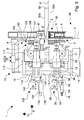
Figure 1 is a perspective view of the painting apparatus according to the invention associated with an element to be machined, in an operating condition; -
Figure 2 is a further perspective view of the apparatus inFigure 1 ; -
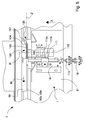
Figure 3 is a side view of the painting apparatus inFigure 1 associated with a partially illustrated operating machine; -
Figure 3A is a partially enlarged view of the apparatus inFigure 3 , showing grooves of a side wall of a painting roller; -
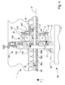
Figure 4 is a front view of the apparatus inFigure 3 ; -
Figure 5 is a top plan view of the apparatus inFigure 3 ; -
Figure 6 is a rear view of the apparatus inFigure 3 ; -
Figure 7 is a section of reservoir means and of paint-applying means of the apparatus inFigure 1 . - With reference to
Figures 1 to 6 , there is schematically illustrated apainting apparatus 1 associated with an operatingmachine 90, for example an edgebanding machine or squaring-edgebanding machine, and comprising arotating painting roller 2 and a furtherrotating painting roller 102, arranged for abutting respectively on a portion to be painted 50a and a further portion to be painted 50b of anelement 50, typically a panel made of wood or similar material, for applying to saidportions - The
painting roller 2 is a conical disc provided with an operatingside wall 3 having a substantially conical shape, arranged for abutting on said portion to be painted 50a. The conicity of theside wall 3, i.e. the corresponding angle at the top of the ideal cone, is comprised between 10° and 45°, for example 20°. - Alternatively, the
painting roller 2 may comprise a disc the side wall of which is formed by a first cylindrical portion and a second conical operating portion, having the aforesaid conicity. - The
painting roller 2 is made of light metal alloy, in particular of aluminium alloy. - The portion to be painted 50a of the
element 50 consists, for example, of a longitudinal joining corner formed by afirst face 50d, for example lower face, of greater extent and aside edge 50c of theelement 50. On saidside edge 50c, in a preceding machining step, a list or ribbon has been glued and fixed. - The
painting roller 2 is rotated around a rotation axis R by arotating motor 15. The rotation axis R is tiltable on a plane that is substantially orthogonal to a resting plane P of saidelement 50 and orthogonal to said longitudinal joiningcorner 50a. In the figures the rotation axis R is horizontal, substantially parallel to said resting plane P. - In operation, as explained in greater detail further on in the description, the
painting roller 2 rolls on theportion 50a of theelement 50 that is driven linearly by conveyingmeans 92 of themachine 90 at a defined advancing speed, in a moving direction M, on the resting plane P. - The
apparatus 1 comprises supportingmeans 10, fixed to a supportingplane 91 of themachine 90, and arranged for slidably supporting thepainting roller 2 and themotor 15, so that thepainting roller 2 and themotor 15 are linearly movable along a first direction X that is substantially parallel to said resting plane P and transverse, in particular substantially orthogonal, to the portion to be painted 50a and to the moving direction M of theelement 50. - The supporting means 10 in fact comprises a
first carriage 11 slidable along the first direction X and supporting thepainting roller 2 and themotor 15. - Linear actuating means 16, comprising, for example, a pneumatic cylinder, is provided for driving said
first carriage 11 along the first direction X, between a first copying operating position A, in which saidpainting roller 2 abuts on, i.e. "copies" the portion to be painted 50a of theelement 50, and a non-operating or excluding position B, in which saidpainting roller 2 is disengaged and spaced apart from said element 50 (Figure 3 ). - Elastic means 31 is provided for exerting on the
first carriage 11 a force of defined intensity directed along the first direction X towards theelement 50, so as to maintain theside wall 3 of thepainting roller 2 in contact with theportion 50a during operation, without, however, damaging the surface of theelement 50. - Alternatively, the linear actuating means 16 can be controlled so as to exert a force of defined intensity on the
painting roller 2 in the operating position A. In the case of a pneumatic cylinder, this control of force can be achieved by a pressure regulator, of known and non-illustrated type, located upstream of valve means, which is also of known and non-illustrated type, arranged for controlling the aforesaid cylinder. - The supporting means 10 is further arranged for moving the
painting roller 2 along a second direction Y that is substantially orthogonal to said first direction X and to said moving direction M. In this manner, it is possible to adjust the position of thepainting roller 2 on the basis of the dimensions and/or the position of theelement 50. - For this purpose, the supporting
means 10 comprises asecond carriage 12, that slidably supports thefirst carriage 11 and the linear actuating means 16. In particular, thesecond carriage 12 comprises linear sliding guides, that are of known type and are not illustrated in the figures, along which thefirst carriage 11 can slide. Thecylinder 16 is fixed to thesecond carriage 12. - The
first carriage 11 is further configured so as to enable the rotation axis R to be tilted, i.e. thepainting roller 2 and themotor 15 to be partially rotated around a tilt axis Z that is substantially orthogonal to the first direction X and to the second direction Y. For this purpose, thecarriage 11, comprises afirst plate 11a that supports themotor 15 and thepainting roller 2 and is removably connected to asecond plate 11b, that is slidably connected to thesecond carriage 12. - The connection between the two
plates first plate 11a to rotate with respect to thesecond plate 11b around the tilt axis Z, which, in particular, substantially coincides with the longitudinal joiningcorner 50a of saidelement 50. Threaded means 37, provided with a respective knob, selectively locks or permits the relative rotation of thefirst plate 11a on thesecond plate 11b. In this manner, by simply rotating thepainting roller 2 around the tilt axis Z it is possible to modify the angle of impact of theside wall 3 on the portion to be painted 50a. - The
second carriage 12 supports, via a pair ofelongated supports 13, for example cylindrical bars, a first fixed supportingmember 32, to which is connected the free end of thestem 18 of thecylinder 16. - A second movable supporting
member 33, to which the body of thepneumatic cylinder 16 is fixed, is connected to thefirst carriage 11 by aprismatic rod 34, slidably supported by the first supportingmember 31. In this manner, the second supportingmember 33, driven by thecylinder 16, is linearly movable along the first direction X towards or away from said first supportingmember 32 so as to position thepainting roller 2 respectively in said operating position A or in said non-operating position B. - Adjusting means 35 enables a minimum distance to be set along said first direction X between said first supporting
member 32 and said second supportingmember 33. In other words, the adjusting means 35 enables the operating position A of the painting roller to be adjusted with precision with respect to theelement 50. - The adjusting means 35 comprises, for example, a threaded
bar 36 engaged in the second supportingmember 33 and arranged for abutting on, at an end, the first supportingmember 32, the opposite end being provided with a. By acting on theknob 39 it is possible to rotate the threadedbar 36 to vary the length of a portion of the threadedbar 36, interposed between said second supportingmember 32 and said supportingmember 33. - The
second carriage 12 is in turn slidably supported by a supportingframe 14 of the supportingmeans 10. In particular, the supportingframe 14 comprises further guides 19, for example a pair of cylindrical rods, along which thesecond carriage 12 can slide. Moving means, of known type and not illustrated, enables thesecond carriage 12 to be moved along the second direction Y. - Driving means 38 is also provided for exerting on the second carriage 12 a force of defined intensity along the second direction Y, so as to maintain the
side wall 3 of thepainting roller 2 in contact with theportion 50a during operation, to perform the copying function of saidpainting roller 2. This driving means 38 comprises, for example, respective elastic means fixed to said supportingframe 14, or alternatively further pneumatic linear actuators. - The supporting
frame 14 of the supportingmeans 10 is fixed to the supportingplane 91 of themachine 90. - It is opportune to observe that by virtue of the conical conformation of the
side wall 3 of thepainting roller 2, the approaching of thepainting roller 2 to the portion to be painted 50a can be performed directly along the first direction X, without the help of feeler pins or copying elements, using only thelinear actuator 16, the elastic means 31 and the driving means 38 being arranged to exert on thepainting roller 2, and thus on the portion to be painted 50a, forces of predefined intensity, respectively along the first direction X and along the second direction Y. - The
further painting roller 102 is identical to thepainting roller 2 and is arranged spaced apart at least along the second direction Y, so as to operate at the same time with a respectiveoperating side wall 103 on the further portion to be painted 50b of theelement 50. The further portion to be painted 50b consists, for example, in a further longitudinal joining corner opposite the longitudinal joining corner and formed by asecond face 50e, for example upper face, parallel and opposite thefirst face 50d, and by theside edge 50c of theelement 50. In particular, thefurther painting roller 102 is substantially superimposed on thepainting roller 2. - Alternatively, the two
painting rollers element 50. This arrangement of thepainting rollers painting rollers - The
further painting roller 102 is rotated around a respective axis R' by afurther motor 115. - The supporting means 10 of the
apparatus 1 comprises a furtherfirst carriage 111 slidable along the first direction X and arranged for supporting thefurther painting roller 102 and thefurther motor 115. Further linear actuating means 116, comprising, for example, a respective pneumatic cylinder, is provided for driving the furtherfirst carriage 111 along the first direction X, between the copying operating position A, and the excluding position B. - Further
elastic means 131 is provided for exerting on the furtherfirst carriage 111 a force of defined intensity along the first direction X, so as to maintain thefurther side wall 103 of thefurther painting roller 102 in contact with thefurther portion 50b during operation. - Alternatively, the further linear actuating means 116 can be controlled so as to exert a force of defined intensity on the
further painting roller 102 in the operating position A. - The further
first carriage 111 is substantially identical to thefirst carriage 11 and is mounted, upturned with respect to thefirst carriage 11, on a furthersecond carriage 112, that is identical to thesecond carriage 12. The furthersecond carriage 112 is mounted slidable on the further guides 19 of the supportingframe 14 so as to be drivable along the second direction Y by further moving means, that is of known type and is not illustrated. Further driving means 138 is provided to exert a force of defined intensity on said furthersecond carriage 112 along the second direction Y, so as to maintain theside wall 103 of thefurther painting roller 102 in contact with thefurther portion 50b during operation. - Similarly to the
first carriage 11, the furtherfirst carriage 111 is configured so as to enable thefurther painting roller 102 and thefurther motor 115 to rotate around a further tilt axis Z' that is substantially orthogonal to the first direction X and to the second direction Y. The furtherfirst carriage 111, in fact comprises a furtherfirst plate 111a that supports thefurther motor 115 and thefurther painting roller 102 and is removably connected to a furthersecond plate 111b. The furthersecond plate 111b is slidably fixed to the furthersecond carriage 112. - The connection between the two
further plates first plate 111a to rotate with respect to the furthersecond plate 111b around the further tilt axis Z' that substantially coincides with the furtherlongitudinal corner 50b of saidelement 50. Further threaded means 137 selectively locks or permits the relative rotation of thefurther plates - The further
second carriage 112 supports by a pair of respectiveelongated supports 113, a further first fixed supportingmember 132 to which is connected the free end of arespective stem 118 of thefurther cylinder 116. A further second movable supportingmember 133, to which the body of thefurther cylinder 116 is fixed, is connected to the furtherfirst carriage 111 by a furtherprismatic rod 134, slidably supported by the further first supportingmember 132. - Further adjusting means 135 enables a minimum distance to be set along said first direction X between said further first supporting
member 132 and said further second supportingmember 133, so as to define the operating position A of thefurther painting roller 102 with respect to theelement 50. - The
side wall painting roller annular scores Figure 3a , which illustrates a detail of thepainting roller 2, thegrooves 4, for example two, are parallel to opposite front faces 5, 6 of saidpainting roller 2. Saidgrooves 4 are spaced apart from one another and from said front faces 5, 6. Eachgroove 4 has a depth, for example, of a few millimetres and has a substantially concavebottom wall 4a. - The
grooves painting rollers element 50. In particular, thegrooves side wall 3, typically at low rotation speeds ofpainting roller 2 and low advancing speeds of theelement 50, such accumulations causing, for example, leaks and dripping of paint onto saidelement 50. - The
grooves - The number of
grooves element 50. - The
painting apparatus 1 comprises applyingelements side walls painting rollers - The applying
elements - In particular, an applying
element 7 is partially inserted into areservoir 20 and arranged for yielding paint to thepainting roller 2, and a further applyingelement 107 is inserted into afurther reservoir 120 and arranged for yielding paint to thefurther painting roller 102. The applyingelements reservoirs element 7 and therespective reservoir 20 will be disclosed below, with particular reference toFigure 7 . - A
first end 71 of the applyingelement 7 is placed abutting on theside wall 3 of thepainting roller 2, whilst asecond end 72 is inserted into thereservoir 20. The paint absorbed by thesecond end 72 is spread owing to the properties of the material up to thefirst end 71. - The
reservoir 20 is arranged near thepainting roller 2, for example is connected to thefirst carriage 11 of the supportingmeans 10 by a bracket or is directly fixed to the supportingplane 91 of themachine 90. - The
reservoir 20 is connected to an external supply circuit of the paint that circulates the paint at a set speed and pressure to maintain the paint in a correct fluid state and to prevent the deposit and/or drying of the paint. For this purpose thereservoir 20 is provided with aninlet 24 and with anoutlet 25 to enable the paint to circulate. Theinlet 24 and theoutlet 25 are connected, by respective pipes, to the supply circuit of the paint, which is of known type and is not illustrated in the figures. - The
reservoir 20 comprises a box element internally subdivided by means of abaffle 23 into afirst chamber 21 and into asecond chamber 22. Thefirst chamber 21, provided with theinlet opening 24 and with the outlet opening 25 contains the paint that is circulated. Thefirst chamber 21 is in communication with thesecond chamber 22 by a passage in thebaffle 23, or through one or more holes obtained on the baffle. Thesecond chamber 22 is arranged for housing thesecond end 72 of the applyingelement 7, inserted therein by arespective opening 26 made on anupper wall 27 of the reservoir means, opposite the passage. - It is opportune to observe that the
reservoir 20 of the invention, subdivided into twochambers second end 72 of the applyingelement 7 to be spaced apart from theinlet 24 and from theoutlet 25. In this manner, it is no longer necessary to cut and shape thesecond end 72, as occurs in known painting apparatuses. - Each applying
element painting apparatus 1 so as to abut substantially tangentially on theside wall respective painting roller first end element painting roller first portion first end second end second portion first end second end second portion reservoir element respective side wall 3, 103 a greater quantity of paint. This enables rotation speeds of thepainting rollers element 50 to be reached that are much higher, nevertheless ensuring a regular and uniform application of the paint without the risk of excessively depriving the first ends 71, 171 of the applyingelements - The operation of the
painting apparatus 1 of the invention provides, in an initial step, linearly moving thepainting rollers operating walls painting rollers element 50. This movement is performed automatically by driving the linear actuating means 16, 116 that moves thefirst carriages - Correctly abutting or copying the
painting rollers element 50 along the first direction X and along the second direction Y is ensured respectively by the elastic means 31, 131 and by the driving means 38, 138. - The
painting rollers motors element 50 is driven linearly by the conveying means 92 of themachine 90 at a defined advancing speed in the moving direction M. - The
painting rollers respective operating walls element 50 tends to drag thepainting rollers - Alternatively, the
painting rollers element 50 can already be moved before the mutual contact. - It is also provided that only the
painting roller 2, or only thefurther painting roller 102, can be driven to apply paint only to the portion to be painted 50a or only to the further portion to be painted 50b. - The dimensions of the
painting rollers element 50 without the need for feeler pins, can be significantly increased with respect to those of the commonly used painting rollers. These dimensions comprise the basic diameters of the front walls and the thickness or height of the roller. - Increasing the dimensions does not affect excessively the weight of the
painting rollers painting rollers - Increasing the dimensions, on the contrary, enables the angle of impact to be reduced, thus ensuring precopying of the panel.
- By virtue of the greater dimensions (in particular the greater diameter), of the reduced moment of inertia, and of the smaller angle of impact, each
painting roller element 50 that is movable at a set advancing speed, does not slide, vibrate or jump, but substantially immediately adapts to the linear motion of theelement 50 rolling thereupon. - This dynamic behaviour in fact enables the advancing speed of the
element 50 to be increased conspicuously, at the same time maintaining regular and uniform contact between eachside wall - The great thickness of each
painting roller portions elements 50 having different thicknesses, without the need to adjust the position of the painting roller along the second direction Y.
Claims (62)
- Apparatus comprising at least a painting roller (2, 102) rotating around a rotation axis (R, R') and provided with a side wall (3, 103) suitable for contacting a portion to be painted (50a, 50b) of an element (50) for applying to said portion to be painted (50a, 50b) a liquid solution, in particular a paint, characterised in that said side wall (3, 103) comprises at least a portion having a conical shape, arranged for contacting said portion to be painted (50a).
- Apparatus according to claim 1, wherein said at least a conical portion of said side wall (3, 103) has a conical angle comprised between 10° and 45°, in particular 20°.
- Apparatus according to claim 1 or 2, wherein said painting roller (2, 102) is movable along a first direction (X), between an operating position (A), in which said side wall (3, 103) is in contact with said portion to be painted (50a, 50b), and an excluding position (B), in which said painting roller (2, 102) is disengaged and spaced apart from said portion to be painted (50a, 50b).
- Apparatus according to claim 3, comprising elastic means (31, 131) acting on said painting roller (2, 102) so that said painting roller (2, 102) exerts on said portion to be painted (50a, 50b) a defined contact force along said first direction (X), in said operating position (A).
- Apparatus according to claim 3 or 4, wherein said first direction (X) is substantially parallel to a resting plane (P) of said element (50) and transverse, in particular substantially perpendicular, to said portion to be painted (50a).
- Apparatus according to claim 5, wherein said painting roller (2, 102) is movable along a second direction (Y) substantially orthogonal to said first direction (X) and to said resting plane (P).
- Apparatus according to claim 6, comprising driving means (38, 138) acting on said painting roller (2, 102) so that said painting roller (2, 102) exerts on said portion to be painted (50a, 50b) a defined contact force along said second direction (Y), in said operating position (A).
- Apparatus according to claim 6 or 7, wherein said painting roller (2, 102) is further rotatable around a tilt axis (Z, Z'), said tilt axis (Z, Z') being substantially orthogonal to said first direction (X) and to said second direction (Y).
- Apparatus according to claim 8, wherein said tilt axis (Z, Z') substantially coincides with a longitudinal corner of said portion to be painted (50a, 50b).
- Apparatus according to any preceding claim, wherein said painting roller (2, 102) is rotated around said rotation axis (R, R') by motor means (15, 115) at a speed that is such that a peripheral speed of said side wall (3, 103) is less than a moving speed of said element (50) along a moving direction (M) by a defined value.
- Apparatus according to any preceding claim, wherein said side wall (3, 103) is provided with at least a peripheral groove (4, 104) suitable for receiving and retaining said liquid solution.
- Apparatus comprising a painting roller (2, 102) rotating around a rotation axis (R, R') and provided with a side wall (3, 103) suitable for abutting on an element (50) to be painted for applying thereupon a liquid solution, in particular paint, characterised in that said side wall (3, 103) comprises at least a groove (4, 104) suitable for containing and/or retaining a quantity of said liquid solution.
- Apparatus according to claim 11 or 12, wherein said at least a groove (4, 104) is annular.
- Apparatus according to any one of claims 11 to 13, wherein said at least a groove (4, 104) is contained on a plane substantially perpendicular to said rotation axis (R).
- Apparatus according to any one of claims 11 to 14, wherein said at least a groove (4) comprises a substantially concave bottom wall (4a).
- Apparatus according to any one of claims 11 to 15, wherein said side wall (3, 103) comprises a plurality of grooves (4, 104) that are parallel to and spaced apart from one another.
- Apparatus according to any preceding claim, comprising a painting roller (2), provided with a side wall (3), and a further painting roller (102), provided with a further side wall (103), said painting roller (2) and said further painting roller (102) being arranged mutually spaced apart so as to abut with the respective side walls (3, 103) on corresponding portions to be painted (50a, 50b) of an edge (50c) of said element (50).
- Apparatus comprising at least a rotating painting roller (2, 102) for applying a liquid solution, in particular a paint, to an element (50) to be painted, an applying element (7, 107) arranged for contacting said painting roller (2, 102) and transferring thereupon said liquid solution, reservoir means (20, 120) containing said liquid solution, provided with an inlet (24) and an outlet (25) to enable said liquid solution to circulate and arranged for housing a portion of said applying element (7, 107), characterised in that said reservoir means (20) comprises a first chamber (21), bearing said inlet (24) and said outlet (25), and a second chamber (22), connected to said first chamber (21) and arranged for housing said portion of said applying element (7, 107), said chambers (21, 22) being separated at least partially by a baffle (23).
- Apparatus according to claim 18, wherein said applying element (7, 107) comprises a first end (71, 171), for contacting said painting roller (2, 102) and transferring thereupon said liquid solution, and a second end (72, 172), opposite said first end (71, 171) and inserted into said second chamber (22) to draw said liquid solution, said applying element (7, 107) being arranged so that said painting roller (2, 102), by rotating, contacts successively a first portion (71a, 171a) of said first end (71, 171) further from said second end (72, 172) and thus a second portion (71b, 171b) of said first end (71, 171) nearer said second end (72, 172).
- Apparatus according to claim 19, wherein said second chamber (22) is shaped and dimensioned substantially complementary to said second end (72, 172).
- Apparatus according to claim 19 or 20, wherein said reservoir means (20) comprises an opening (26) for inserting said second end (72, 172) in said second chamber (22).
- Apparatus according to any one of claims 18 to 21, wherein said applying element (7, 107) comprises an elongated element made of flexible and impregnable material, in particular felt.
- Apparatus according to any one of claims 19 to 22, as claim 22 is appended to any one of claims 19 to 21, wherein said first end (71, 171) is positioned so as to contact said side wall (3, 103) in a substantially tangential manner.
- Apparatus according to any one of claims 18 to 23, wherein said painting roller (2, 102) comprises a side wall (3, 103) provided with at least a portion having a conical shape, arranged for abutting on a portion to be painted (50a, 50b) of said element (50).
- Apparatus according to claim 24, wherein said at least a conical portion of said side wall (3, 103) has a conical angle comprised between 10° and 45°, in particular 20°.
- Apparatus according to claim 24 or 25, wherein said painting roller (2, 102) is movable along a first direction (X), between an operating position (A), in which said side wall (3, 103) is in contact with said portion to be painted (50a, 50b), and an excluding position (B), in which said painting roller (2, 102) is disengaged and spaced apart from said portion to be painted (50a, 50b).
- Apparatus according to claim 26, comprising actuating means (16, 116) arranged for driving said painting roller (2, 102) along said first direction (X) at least between said operating position (A) and said excluding position (B).
- Apparatus according to claim 26 or 27, comprising elastic means (31, 131) acting on said painting roller (2, 102) so that said painting roller (2, 102) exerts on said portion to be painted (50a, 50b) a defined contact force along said first direction (X), in said operating position (A).
- Apparatus according to any one of claims 26 to 28, wherein said first direction (X) is substantially parallel to a resting plane (P) of said element (50) and transverse, in particular substantially perpendicular, to said portion to be painted (50a, 50b).
- Apparatus according to claim 29, wherein said painting roller (2, 102) is movable along a second direction (Y) substantially orthogonal to said first direction (X) and to said resting plane (P).
- Apparatus according to claim 30, comprising driving means (38, 138) acting on said painting roller (2, 102) so that said painting roller (2, 102) exerts on said portion to be painted (50a, 50b) a defined contact force along said second direction (Y), in said operating position (A).
- Apparatus according to claim 30 or 31, wherein said painting roller (2, 102) is further rotatable around a tilt axis (Z, Z'), said tilt axis (Z, Z') being substantially orthogonal to said first direction (X) and to said second direction (Y).
- Apparatus according to any one of claims 24 to 32, wherein said painting roller (2, 102) is rotated around a rotation axis (R, R') by motor means (15, 115) at a speed that is such that a peripheral speed of said side wall (3, 103) is less than a moving speed of said element (50) along a moving direction (M) by a defined value.
- Apparatus according to claim 33, wherein said painting roller (2, 102) comprises a disc made of light metal alloy, in particular aluminium alloy, for reducing a moment of inertia of said painting roller (2, 102) with respect to said rotation axis (R, R').
- Apparatus according to any one of claims 24 to 34, wherein said side wall (3, 103) is provided with at least a peripheral groove (4, 104) suitable for receiving and/or retaining said liquid solution.
- Apparatus according to claim 35, wherein said at least a groove (4, 104) is annular.
- Apparatus according to claim 35 or 36, as claim 35 is appended to claim 33 or 34, wherein said at least a groove (4, 104) is contained on a plane substantially perpendicular to said rotation axis (R, R').
- Apparatus according to any one of claims 35 to 37, wherein said at least a groove (4) comprises a substantially concave bottom wall (4a).
- Apparatus according to any one of claims 35 to 38, wherein said side wall (3, 103) comprises a plurality of grooves (4, 104) that are parallel to and spaced apart from one another.
- Apparatus comprising at least a rotating painting roller (2, 102) arranged for applying a liquid solution, in particular a paint, on an element (50) to be painted, and at least an applying element (7, 107) provided with a first end (71, 171), for contacting said painting roller (2, 102) and transferring thereupon said liquid solution, and a second end (72, 172), opposite said first end (71, 171), for withdrawing said liquid solution from reservoir means (20, 120), characterised in that said applying element (7, 107) is arranged so that said painting roller (2, 102), by rotating, successively contacts a first portion (71a, 171a) of said first end (71, 171) further from said second end (72, 172) and then a second portion (71b, 171b) of said first end (71, 171) nearer said second end (72, 172).
- Apparatus according to claim 40, wherein said applying element (7, 107) comprises an elongated element made of flexible and impregnable material, in particular felt.
- Apparatus according to claim 40 or 41, wherein said first end (71, 171) is positioned so as to contact said side wall (3, 103) in a substantially tangential manner.
- Apparatus according to claim 41 or 42, as claim 42 is appended to claim 41, wherein said second end (72, 172) is inserted into said reservoir means (20, 120) for absorbing said liquid solution.
- Apparatus according to claim 43, wherein said second portion (71b, 171b), nearer said second end (72, 172), is more impregnated with said liquid solution than is said first portion (71a, 171a).
- Apparatus according to any one of claims 40 to 44, wherein said reservoir means (20) comprises a first chamber (21), bearing an inlet (24) and an outlet (25) for the circulation of said liquid solution, and a second chamber (22), connected to said first chamber (21) and arranged for housing said second end (72, 172) of said applying element (7, 107), said chambers (21, 22) being separated at least partially by a baffle (23).
- Apparatus according to claim 45, wherein said second chamber (22) is shaped and dimensioned substantially complementary to said second end (72, 172) of said applying element (7, 107).
- Apparatus according to any one of claims 40 to 46, wherein said painting roller (2, 102) comprises a side wall (3, 103) provided with at least a portion having a conical shape, arranged for contacting a portion to be painted (50a, 50b) of said element (50).
- Apparatus according to claim 47, wherein said at least a conical portion of said side wall (3) has a conical angle comprised between 10° and 45°, in particular 20°.
- Apparatus according to claim 47 or 48, wherein said painting roller (2, 102) is movable along a first direction (X), between an operating position (A), in which said side wall (3, 103) is in contact with said portion to be painted (50a, 50b), and an excluding position (B), in which said painting roller (2, 102) is disengaged and spaced apart from said portion to be painted (50a, 50b).
- Apparatus according to claim 49, comprising actuating means (16, 116) arranged for driving said painting roller (2, 102) along said first direction (X) at least between said operating position (A) and said excluding position (B).
- Apparatus according to claim 49 or 50, comprising elastic means (31, 131) acting on said painting roller (2, 102) so that said painting roller (2, 102) exerts on said portion to be painted (50a, 50b) a defined contact force along said first direction (X), in said operating position (A).
- Apparatus according to any one of claims 49 to 51, wherein said first direction (X) is substantially parallel to a resting plane (P) of said element (50) and transverse, in particular substantially perpendicular, to said portion to be painted (50a, 50b).
- Apparatus according to claim 52, wherein said painting roller (2, 102) is movable along a second direction (Y) substantially orthogonal to said first direction (X) and to said resting plane (P).
- Apparatus according to claim 53, comprising driving means (38, 138) acting on said painting roller (2, 102) so that said painting roller (2, 102) exerts on said portion to be painted (50a, 50b) a defined contact force along said second direction (Y), in said operating position (A).
- Apparatus according to claim 53 or 54, wherein said painting roller (2, 102) is further rotatable around a tilt axis (Z, Z'), said tilt axis (Z, Z') being substantially orthogonal to said first direction (X) and to said second direction (Y).
- Apparatus according to any one of claims 47 to 55, wherein said painting roller (2, 102) is rotated around a rotation axis (R, R') by motor means (15, 115) at a speed that is such that a peripheral speed of said side wall (3, 103) is less than a moving speed of said element (50) along a moving direction (M) by a defined value.
- Apparatus according to claim 56, wherein said painting roller (2, 102) comprises a disc made of light metal alloy, in particular aluminium alloy, for reducing a moment of inertia of said painting roller (2, 102) with respect to said rotation axis (R, R').
- Apparatus according to any one of claims 47 to 57, wherein said side wall (3, 103) is provided with at least a peripheral groove (4, 104) suitable for receiving and/or retaining said liquid solution.
- Apparatus according to claim 58, wherein said at least a groove (4, 104) is annular.
- Apparatus according to claim 58 or 59, as claim 58 is appended to claim 56 or 57, wherein said at least a groove (4, 104) is contained on a plane substantially perpendicular to said rotation axis (R, R').
- Apparatus according to any one of claims 58 to 60, wherein said at least a groove (4) comprises a substantially concave bottom wall (4a).
- Apparatus according to any one of claims 58 to 61, wherein said side wall (3, 103) comprises a plurality of grooves (4, 104) that are parallel to and spaced apart from one another.
Applications Claiming Priority (1)
| Application Number | Priority Date | Filing Date | Title |
|---|---|---|---|
| ITMO20070328 ITMO20070328A1 (en) | 2007-10-30 | 2007-10-30 | TINTING EQUIPMENT |
Publications (2)
| Publication Number | Publication Date |
|---|---|
| EP2158973A2 true EP2158973A2 (en) | 2010-03-03 |
| EP2158973A3 EP2158973A3 (en) | 2010-09-15 |
Family
ID=40313935
Family Applications (1)
| Application Number | Title | Priority Date | Filing Date |
|---|---|---|---|
| EP08167360A Withdrawn EP2158973A3 (en) | 2007-10-30 | 2008-10-23 | Painting apparatus |
Country Status (2)
| Country | Link |
|---|---|
| EP (1) | EP2158973A3 (en) |
| IT (1) | ITMO20070328A1 (en) |
Citations (1)
| Publication number | Priority date | Publication date | Assignee | Title |
|---|---|---|---|---|
| US20020185063A1 (en) | 2001-06-12 | 2002-12-12 | Roan Kuang-Wen | Sealing roller glue tank |
Family Cites Families (13)
| Publication number | Priority date | Publication date | Assignee | Title |
|---|---|---|---|---|
| US3103689A (en) * | 1960-08-01 | 1963-09-17 | Borisof Bernard | Roller applicators |
| US3185130A (en) * | 1962-02-12 | 1965-05-25 | M & T Chemicals Inc | Multiple roller coating apparatus |
| US3331093A (en) * | 1964-11-12 | 1967-07-18 | Theresa E Mayden | Pressurized paint supply assembly with extension applicator |
| US3524781A (en) * | 1966-03-02 | 1970-08-18 | American Can Co | Application of thin line adhesive to a sheet using a grooved roll as applicator |
| ES346996A1 (en) * | 1966-11-11 | 1969-04-16 | Becker Alfred | A method for the protection of nude places of metal sheet otherwise coated. (Machine-translation by Google Translate, not legally binding) |
| US3702739A (en) * | 1971-03-11 | 1972-11-14 | James M Rentfrow | Paint roller |
| JPS59189960A (en) * | 1983-04-11 | 1984-10-27 | Yokohama Rubber Co Ltd:The | Applicator for adhesive agent |
| WO1998042187A1 (en) * | 1997-03-24 | 1998-10-01 | Green Management Limited | Apparatus for the selective application of liquid media |
| DE29716055U1 (en) * | 1997-09-06 | 1997-10-23 | Franke, Michel, 10559 Berlin | Joint roller |
| DE19754684A1 (en) * | 1997-12-10 | 1999-06-17 | Pagendarm Technologie Gmbh | Device for application of fluid or paste medium, especially adhesive |
| JP4756732B2 (en) * | 2000-11-15 | 2011-08-24 | 名阪真空工業株式会社 | Manufacturing method of plate-like coated product and coating apparatus suitable for it |
| SE527570C2 (en) * | 2004-10-05 | 2006-04-11 | Vaelinge Innovation Ab | Device and method for surface treatment of sheet-shaped material and floor board |
| DE202005006368U1 (en) * | 2005-04-20 | 2005-06-30 | Nordson Corporation, Westlake | Applicator for applying fluid to contour of substrate, e.g. for floor covering panel manufacture, has transfer wheel with axially-tapered fluid-conveying surface |
-
2007
- 2007-10-30 IT ITMO20070328 patent/ITMO20070328A1/en unknown
-
2008
- 2008-10-23 EP EP08167360A patent/EP2158973A3/en not_active Withdrawn
Patent Citations (1)
| Publication number | Priority date | Publication date | Assignee | Title |
|---|---|---|---|---|
| US20020185063A1 (en) | 2001-06-12 | 2002-12-12 | Roan Kuang-Wen | Sealing roller glue tank |
Also Published As
| Publication number | Publication date |
|---|---|
| ITMO20070328A1 (en) | 2009-04-30 |
| EP2158973A3 (en) | 2010-09-15 |
Similar Documents
| Publication | Publication Date | Title |
|---|---|---|
| US4705438A (en) | Machining center having an inclinable vacuum-holding worktable | |
| KR101050151B1 (en) | Coating method and device on sheet surface | |
| US6832879B2 (en) | Machine tool for at least partial contour-dependent cutting or milling | |
| EP0916448B1 (en) | Method and apparatus for polishing both sides of optical lenses | |
| EP1314513B1 (en) | Apparatus for trimming of glass plates | |
| DE69501670T2 (en) | Machine for treating ski soles, in particular by grinding | |
| CN105855110A (en) | Automatic spraying and coating equipment for foam boards | |
| CN216368695U (en) | Paperboard gluing device | |
| CN213194317U (en) | Protective film glue volume adjustable glue coating mechanism | |
| CN219880446U (en) | Glue spreader for processing automobile parts | |
| CN104722451B (en) | A kind of bridge veneer device for painting | |
| KR100911635B1 (en) | Polarizing film producing device | |
| CN216727805U (en) | Automatic spraying equipment for furniture boards | |
| CN206230359U (en) | Tilting sheet material burnishing device | |
| ITMO20070328A1 (en) | TINTING EQUIPMENT | |
| JP3817040B2 (en) | Knife application system | |
| CN210024668U (en) | Slicer cutter cutting edge grinding device | |
| CN217991875U (en) | Quick locking cutter burnishing device | |
| DE102010047557B4 (en) | Machine tool with automatic clamping device for the chain of a tool magazine | |
| JPH09216205A (en) | Putty agent applying device of putty repair machine for plate material | |
| DE4304478A1 (en) | Application device | |
| CN223417503U (en) | A spraying jig for roller surface processing | |
| CN219723554U (en) | Automatic rubber coating structure of iron axle global | |
| CN218928912U (en) | Screen printer | |
| CN115608555B (en) | MiniLED circuit board coating device |
Legal Events
| Date | Code | Title | Description |
|---|---|---|---|
| PUAI | Public reference made under article 153(3) epc to a published international application that has entered the european phase |
Free format text: ORIGINAL CODE: 0009012 |
|
| AK | Designated contracting states |
Kind code of ref document: A2 Designated state(s): AT BE BG CH CY CZ DE DK EE ES FI FR GB GR HR HU IE IS IT LI LT LU LV MC MT NL NO PL PT RO SE SI SK TR |
|
| AX | Request for extension of the european patent |
Extension state: AL BA MK RS |
|
| PUAL | Search report despatched |
Free format text: ORIGINAL CODE: 0009013 |
|
| AK | Designated contracting states |
Kind code of ref document: A3 Designated state(s): AT BE BG CH CY CZ DE DK EE ES FI FR GB GR HR HU IE IS IT LI LT LU LV MC MT NL NO PL PT RO SE SI SK TR |
|
| AX | Request for extension of the european patent |
Extension state: AL BA MK RS |
|
| 17P | Request for examination filed |
Effective date: 20110315 |
|
| AKX | Designation fees paid |
Designated state(s): AT DE ES FR GB |
|
| GRAP | Despatch of communication of intention to grant a patent |
Free format text: ORIGINAL CODE: EPIDOSNIGR1 |
|
| STAA | Information on the status of an ep patent application or granted ep patent |
Free format text: STATUS: THE APPLICATION IS DEEMED TO BE WITHDRAWN |
|
| 18D | Application deemed to be withdrawn |
Effective date: 20121103 |