EP2157740A1 - Radio local area network (lan) system - Google Patents
Radio local area network (lan) system Download PDFInfo
- Publication number
- EP2157740A1 EP2157740A1 EP08740594A EP08740594A EP2157740A1 EP 2157740 A1 EP2157740 A1 EP 2157740A1 EP 08740594 A EP08740594 A EP 08740594A EP 08740594 A EP08740594 A EP 08740594A EP 2157740 A1 EP2157740 A1 EP 2157740A1
- Authority
- EP
- European Patent Office
- Prior art keywords
- slaves
- master
- received
- slave
- signal
- Prior art date
- Legal status (The legal status is an assumption and is not a legal conclusion. Google has not performed a legal analysis and makes no representation as to the accuracy of the status listed.)
- Withdrawn
Links
Images




Classifications
-
- H—ELECTRICITY
- H04—ELECTRIC COMMUNICATION TECHNIQUE
- H04W—WIRELESS COMMUNICATION NETWORKS
- H04W40/00—Communication routing or communication path finding
- H04W40/34—Modification of an existing route
-
- H—ELECTRICITY
- H04—ELECTRIC COMMUNICATION TECHNIQUE
- H04W—WIRELESS COMMUNICATION NETWORKS
- H04W56/00—Synchronisation arrangements
- H04W56/001—Synchronization between nodes
-
- H—ELECTRICITY
- H04—ELECTRIC COMMUNICATION TECHNIQUE
- H04L—TRANSMISSION OF DIGITAL INFORMATION, e.g. TELEGRAPHIC COMMUNICATION
- H04L12/00—Data switching networks
- H04L12/28—Data switching networks characterised by path configuration, e.g. LAN [Local Area Networks] or WAN [Wide Area Networks]
-
- H—ELECTRICITY
- H04—ELECTRIC COMMUNICATION TECHNIQUE
- H04W—WIRELESS COMMUNICATION NETWORKS
- H04W40/00—Communication routing or communication path finding
- H04W40/02—Communication route or path selection, e.g. power-based or shortest path routing
-
- H—ELECTRICITY
- H04—ELECTRIC COMMUNICATION TECHNIQUE
- H04W—WIRELESS COMMUNICATION NETWORKS
- H04W84/00—Network topologies
- H04W84/18—Self-organising networks, e.g. ad-hoc networks or sensor networks
- H04W84/20—Leader-follower arrangements
-
- H—ELECTRICITY
- H04—ELECTRIC COMMUNICATION TECHNIQUE
- H04W—WIRELESS COMMUNICATION NETWORKS
- H04W24/00—Supervisory, monitoring or testing arrangements
- H04W24/04—Arrangements for maintaining operational condition
Definitions
- the present invention generally relates to a wireless local area network (LAN) system. More specifically, the present invention relates to a LAN system in a relatively small space such as a home or office.
- LAN wireless local area network
- IEEE 802.11a/g/b-based wireless LANs have become common for home use. Higher speed wireless standards are also under development.
- wireless LANs As home network infrastructure by the distribution of AV streams using a high-speed wireless LAN, a home security sensor (glass breakage detection) using the easiness of wireless installation, and the like.
- wireless LANs are susceptible to blocking objects, noise caused by electromagnetic waves, and the like.
- millimeter waves, UWB, etc. for high-speed wireless LANs are susceptible to obstacles and the like.
- UWB ultra-wide band
- wireless LANs are premised on an ad-hoc connection (which is not continuous communication but a dynamic network connection).
- wireless disconnection is not recognized as an abnormal condition.
- the IEEE 802.15.3 standard and the like do not even consider a mechanism for treating wireless disconnection as an abnormal condition.
- there is no mechanism for notifying communication disconnection in a wireless network layer Particularly, in the case of a network where a wired portion is tunneled (an IP packet or Ethernet frame is encapsulated), a device on the Ethernet side considers wireless disconnection as an unexplained communication failure.
- Japanese Unexamined Patent Publication (Kokai) No. 2004-282758 discloses a method in which, in a wireless network which is controlled by a single controller, when the controller breaks down (or stops) the controller is switched to an alternative controller and network control is performed using the alternative controller, whereby the wireless network is maintained.
- this method is not to circumvent a situation where wireless communication becomes impossible under the influence of a blocking object, noise caused by an electromagnetic wave, or the like.
- Patent Document 1 Japanese Unexamined Patent Publication (Kokai) No. 2004-282758
- wireless communication becomes impossible involves not only the case where communication cannot be performed at all but also the case in which communication cannot be performed stably (e.g., the case in which communication frequently or intermittently is lost).
- a wireless LAN system comprising: a relay which can communicate with an external system; a master which can communicate with the relay; and a plurality of slaves which can wirelessly communicate with the master, the plurality of slaves including a first group and a second group, the first group comprising an alternative slave having a function of transmitting, when a portion of the slaves cannot receive a synchronization signal from the master, an information signal received from the master to the portion of slaves, and the second group including non-alternative slaves not having the function of transmitting the information signal to the portion of slaves.
- a wireless communication method between a master and a plurality of slaves which are included in a wireless LAN system, comprising the steps of: transmitting a first synchronization signal to the plurality of slaves from the master; transmitting a first received signal to the master from a slave having received the first synchronization signal; sending a second synchronization signal from a specific slave among the plurality of slaves to other slaves; transmitting a second received signal to the specific slave from slaves having received the second synchronization signals; transmitting an information signal to the specific slave from the master; and transmitting the information signal from the specific slave to a slave not having sent a first received signal among the slaves having received the second synchronization signals.
- an alternative communication route between the master and the portion of slaves can be automatically secured.
- a specific slave among slaves automatically substitutes for (relays) the master, whereby the communication between the master and the portion of slaves can be maintained.
- the communication route can automatically revert to the one used before occurrence of the failure.
- a communication (service) between a master and slaves can be maintained.
- PICONET refers to a wireless communication subnet defined by IEEE 802.15.3.
- a and B the following contents (A and B) are disclosed.
- a ChildPICONET which appears below refers to the minimum unit of a network defined by IEEE 802.15.3.
- IP#1 to IP#4 represent LAN devices (PCs, various household electrical appliances, or the like) assigned to the respective DEVs.
- IP#n also represents an Ethernet MAC address or an IP address of an IP packet, which corresponds to each device. The meaning of IP#n is also the same in other drawings.
- IEEE 802.15.3 defines that devices in a PICONET can mutually communicate. In communication that provides an Internet connection to a home, communication between DEVs also uses a route of DEV->PNC->DEV for the following reasons:
- Fig. 2 shows a system configuration in the present invention for securing another route during failure (wireless disconnection).
- PNC 100 There is one PNC 100.
- DEVs are of two types: DEV-A and DEV-B.
- DEV-As 110 have the function of becoming a PNC of a child PICONET.
- DEVs-B 120 do not have the function of becoming a PNC.
- the PNC periodically sends a beacon (synchronization signal) to inform each DEV of its presence. Sending of a beacon is performed based on IEEE 802.15.3.
- DEVs-A periodically transmit a "static connection info" packet.
- the PNC has (a) switching table and (b) connection table shown in Fig. 6 , in order to manage a connection relationship with each DEV.
- #1 and #2 are entered as DEVs (DEVs-A) of type A.
- the term "static" in (b) connection table refers to a static connection. (#2) and (#1) shown next to the terms “static” respectively indicate that the DEV-A (#1) can see (communicate with) the DEV-A (#2) and vice versa. If the PNC does not receive a "static connection info" packet for a certain period of time, the PNC determines that the DEVs-A cannot be seen.
- a DEV-B that requires a static connection periodically multicasts a "static connection info" packet.
- the "static connection info" packet is the same as the one used to verify the presence of a DEV-A.
- Fig. 7 shows a table for the case in which a DEV-B (#5) in Fig. 2 is registered as IP#5.
- (b) connection table in Fig. 7 shows that the DEV-B with #5 is static and can be connected to the DEVs-A with #1 and #2.
- a DEV-B that does not require a static connection i.e., a DEV-B using an ad-hoc connection, does not multicast a "static connection info" packet.
- This DEV-B operates as defined in IEEE 802.15.3.
- Fig. 8 shows a table for the case in which a DEV-B (#4) in Fig. 2 is registered as IP#4.
- connection table in Fig. 8 information that the DEV-B with #4 is ad hoc is entered. As such, by using a connection table, even when both static and ad-hoc devices are present, the devices can be appropriately managed.
- a selection of another route is performed in the manner shown below using switching tables managed by PMC/DEV-A.
- connection table For a method for recognizing, in a wireless layer, occurrence of failure in a wireless portion and alerting notified failure, first, whether a connection request by each DEV is static or ad hoc is managed using a connection table. When a situation different from a normal one occurs, the PNC or a DEV provides a notification. The notification is performed by an email, sound, phone call, or the like. Information that a notification is being provided is entered in and managed by the connection table.
- a PNC of the present invention operates as a PC based dedicated device, for example, by SW which operates thereon.
- a DEV-A of the present invention is installed in a room, for example, so as to be seen from a plurality of DEVs-B and the PNC (in a wirelessly communicable manner).
- a DEV-A is provided as a box-type device having an Eth/millimeter-wave interface, for example.
- Such a device can incorporate embedded software (SW) for implementing a method of the present invention.
- SW embedded software
- the device is operated based on some kind of embedded OS and functions as a driver for operating hardware (HW) of the Eth/millimeter-wave interface included in the device.
- a DEV-B of the present invention is a terminal personal computer (PC), for example, the DEV-B is operated by software which is supplied with a millimeter-wave wireless LAN card.
- the DEV-B is an external device (when the DEV-B is a LAN-compatible security device or household electrical appliance which cannot expand a card as in a PC)
- the DEV-B is operated by embedded SW which operates in a box-type device, as with the DEV-A.
Landscapes
- Engineering & Computer Science (AREA)
- Computer Networks & Wireless Communication (AREA)
- Signal Processing (AREA)
- Mobile Radio Communication Systems (AREA)
- Small-Scale Networks (AREA)
Abstract
Description
- The present invention generally relates to a wireless local area network (LAN) system. More specifically, the present invention relates to a LAN system in a relatively small space such as a home or office.
- In recent years, IEEE 802.11a/g/b-based wireless LANs have become common for home use. Higher speed wireless standards are also under development. In the industry, there are trends to place wireless LANs as home network infrastructure by the distribution of AV streams using a high-speed wireless LAN, a home security sensor (glass breakage detection) using the easiness of wireless installation, and the like.
- Meanwhile, due to characteristics of radio waves, wireless LANs are susceptible to blocking objects, noise caused by electromagnetic waves, and the like. Particularly, millimeter waves, UWB, etc., for high-speed wireless LANs are susceptible to obstacles and the like. In order to spread high-speed wireless LANs as home network infrastructure, there is a need to take measures against such interference.
- However, wireless LANs are premised on an ad-hoc connection (which is not continuous communication but a dynamic network connection). Thus, wireless disconnection is not recognized as an abnormal condition. The IEEE 802.15.3 standard and the like do not even consider a mechanism for treating wireless disconnection as an abnormal condition. Also, there is no mechanism for notifying communication disconnection in a wireless network layer. Particularly, in the case of a network where a wired portion is tunneled (an IP packet or Ethernet frame is encapsulated), a device on the Ethernet side considers wireless disconnection as an unexplained communication failure.
- The development of the high-speed wireless LAN is still at an experimental stage towards the practical use. In current measures, circumventing measures from the viewpoint of devising strategies for prevention of radio interference, such as "sending radio waves from a location with a clear view using a waveguide" or "appropriately adjusting an output" is mainstream.
- As a conventional technique, Japanese Unexamined Patent Publication (Kokai) No.
2004-282758
[Patent Document 1]
Japanese Unexamined Patent Publication (Kokai) No. 2004-282758 - It is an object of the present invention to automatically maintain a communication (service) when radio interference occurs in a wireless LAN system.
- It is another object of the present invention to circumvent a situation where wireless communication becomes impossible in a wireless LAN system under the influence of a blocking object, noise caused by an electromagnetic wave, or the like. Note that the expression "wireless communication becomes impossible" as used herein involves not only the case where communication cannot be performed at all but also the case in which communication cannot be performed stably (e.g., the case in which communication frequently or intermittently is lost).
- According to one aspect of the present invention, there is provided a wireless LAN system comprising: a relay which can communicate with an external system; a master which can communicate with the relay; and a plurality of slaves which can wirelessly communicate with the master, the plurality of slaves including a first group and a second group, the first group comprising an alternative slave having a function of transmitting, when a portion of the slaves cannot receive a synchronization signal from the master, an information signal received from the master to the portion of slaves, and the second group including non-alternative slaves not having the function of transmitting the information signal to the portion of slaves.
- According to another aspect of the present invention, there is provided a wireless communication method between a master and a plurality of slaves which are included in a wireless LAN system, comprising the steps of: transmitting a first synchronization signal to the plurality of slaves from the master; transmitting a first received signal to the master from a slave having received the first synchronization signal; sending a second synchronization signal from a specific slave among the plurality of slaves to other slaves; transmitting a second received signal to the specific slave from slaves having received the second synchronization signals; transmitting an information signal to the specific slave from the master; and transmitting the information signal from the specific slave to a slave not having sent a first received signal among the slaves having received the second synchronization signals.
- According to the present invention, even when communication becomes impossible between a master and a portion of slaves in a wireless LAN system due to wireless communication failure caused by an obstacle, noise, or the like, an alternative communication route between the master and the portion of slaves can be automatically secured.
- According to the present invention, when communication becomes impossible between a master and a portion of slaves in a wireless LAN system due to wireless communication failure caused by an obstacle, noise, or the like, a specific slave among slaves automatically substitutes for (relays) the master, whereby the communication between the master and the portion of slaves can be maintained.
- According to the present invention, when wireless communication failure caused by an obstacle, noise, or the like in a wireless LAN system is removed, the communication route can automatically revert to the one used before occurrence of the failure.
- According to the present invention, regardless of occurrence of wireless communication failure caused by an obstacle, noise, or the like in a wireless LAN system, a communication (service) between a master and slaves can be maintained.
- The present invention will be described below with reference to the drawings. The following description is premised on the use of PICONET based on the IEEE 802.15.3 standard. However, the present invention is not limited to this premise and other standards, methods, or the like, can of course be used.
- In one embodiment of the present invention, a system for transmitting and receiving LAN packets in an IEEE 802.15.3 PICONET is assumed. PICONET refers to a wireless communication subnet defined by IEEE 802.15.3. In the present embodiment, the following contents (A and B) are disclosed. Note that a ChildPICONET which appears below refers to the minimum unit of a network defined by IEEE 802.15.3.
-
- A. System for dynamically securing another route using a ChildPICONET, when a failure (wireless disconnection) occurs
- (a-1) System configuration for securing another route during failure (wireless disconnection)
- (a-2) Method for detecting occurrence of failure (wireless disconnection), by each device in the system
- (a-3) Method for selecting another route
- (a-4) Method for detecting recovery from failure and reverting to the original route
- B. Method for recognizing, in a wireless layer, occurrence of failure in a wireless portion between specific devices and alerting notified failure
-
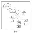
Fig. 1 shows a basic configuration of a LAN packet communication system using a PICONET, according to the present invention. In this configuration, a PNC (PICONET coordinator) 10 for controlling a PICONET is wirelessly connected to a plurality of DEVs (DEVices) 20 and a LAN packet is tunneled (or protocol-converted). The PNC 10 is connected to an external system via a relay (not shown). In optical communication (FTTH), a relay includes a converter for converting light into an electrical signal (millimeter wave or the like). Aline 30 between thePNC 10 and eachDEV 20 means the presence of a wireless communication route. The meaning of thelines 30 is also the same in other drawings.IP# 1 toIP# 4 represent LAN devices (PCs, various household electrical appliances, or the like) assigned to the respective DEVs. At the same time, IP#n also represents an Ethernet MAC address or an IP address of an IP packet, which corresponds to each device. The meaning of IP#n is also the same in other drawings. - IEEE 802.15.3 defines that devices in a PICONET can mutually communicate. In communication that provides an Internet connection to a home, communication between DEVs also uses a route of DEV->PNC->DEV for the following reasons:
- (a) a PNC is only one gateway to the Internet; and
- (b) the DEVs are not always installed in communicable areas.
Although the connection to the PICONET is ad hoc, a route of a LAN packet is configured by a combination of DEVs and the PNC. In order to expand a wireless coverage, IEEE 802.15.3 also defines that a child PICONET can be used. -
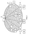
Fig. 2 shows a system configuration in the present invention for securing another route during failure (wireless disconnection). There is onePNC 100. DEVs are of two types: DEV-A and DEV-B. DEV-As 110 have the function of becoming a PNC of a child PICONET. DEVs-B 120 do not have the function of becoming a PNC. - Referring to
Figs. 3 to 5 , a process flow performed during failure (wireless disconnection) is shown below. - (1) In
Fig. 3 , in one PICONET which is normally managed by aPNC 100, thePNC 100, DEVs-A, and DEVs-B perform wireless communication. Specifically, LAN packet communication is performed with LAN devices (IP#n). InFig. 3 , for example, thePNC 100 communicates withIP# 3 of a DEV-B 122. - (2) In
Fig. 4 , when anobstacle 200 or the like is placed, some DEVs-B become unable to communicate with thePNC 100. InFig. 4 , two DEVs-B, i.e., a DEV-B 122 (IP#3) and a DEV-B 124 (IP#4), cannot communicate with thePNC 100. - (3) In
Fig. 5 , a DEV-A 112 which has detected a failure (wireless disconnection) operates as an alternative PNC and creates a child PICONET. InFig. 5 , the DEV-B122 (IP#3) and the DEV-B124 (IP#4) which have become unable to communicate with thePNC 100 switch their connections to the DEV-A 112 (PNC). LAN packets are transmitted through an alternative route of PNC 100-DEV-A 112-DEV-B 122/124. - (4) When the failure is removed, the route reverts to the original one shown in
Fig. 3 . - The operation of the system in the present invention exemplified in
Figs. 2 to 5 has the following two features. - (1) In a conventional method for selecting an alternative route for a network failure, complex routing information exchange based on a routing protocol is performed. In the present invention, however, only by multicasting by a device a packet for notifying other devices of its presence, switching to an alternative route is performed. The method of the present invention is different from a conventional one in which the load of routing information exchange is heavy and a route request is made during failure, and thus, fast switching to an alternative route is performed.
- (2) In the present invention, handling devices that require a static connection in distinction from devices (ad hoc) that do not require a static connection can prevent an increase in system load caused by activation of an unnecessary alternative route.
- The PNC periodically sends a beacon (synchronization signal) to inform each DEV of its presence. Sending of a beacon is performed based on IEEE 802.15.3. DEVs-A periodically transmit a "static connection info" packet. The PNC has (a) switching table and (b) connection table shown in
Fig. 6 , in order to manage a connection relationship with each DEV. In (b) connection table inFig. 6 , #1 and #2 are entered as DEVs (DEVs-A) of type A. The term "static" in (b) connection table refers to a static connection. (#2) and (#1) shown next to the terms "static" respectively indicate that the DEV-A (#1) can see (communicate with) the DEV-A (#2) and vice versa. If the PNC does not receive a "static connection info" packet for a certain period of time, the PNC determines that the DEVs-A cannot be seen. - Among DEVs of type B, a DEV-B that requires a static connection periodically multicasts a "static connection info" packet. The "static connection info" packet is the same as the one used to verify the presence of a DEV-A.
Fig. 7 shows a table for the case in which a DEV-B (#5) inFig. 2 is registered asIP# 5. (b) connection table inFig. 7 shows that the DEV-B with #5 is static and can be connected to the DEVs-A with #1 and #2. - A DEV-B that does not require a static connection, i.e., a DEV-B using an ad-hoc connection, does not multicast a "static connection info" packet. This DEV-B operates as defined in IEEE 802.15.3.
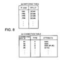
Fig. 8 shows a table for the case in which a DEV-B (#4) inFig. 2 is registered asIP# 4. In (b) connection table inFig. 8 , information that the DEV-B with #4 is ad hoc is entered. As such, by using a connection table, even when both static and ad-hoc devices are present, the devices can be appropriately managed. - A selection of another route is performed in the manner shown below using switching tables managed by PMC/DEV-A.
- (1) In
Fig. 9 , in a normal state, based on (b) switching table of thePNC 100, a LAN packet is encapsulated by a protocol of a wireless portion to perform tunneling.Fig. 9 shows a state in which, after #4 inFig. 8 is recognized, DEVs-B with #3 and #6 are further connected. - (2) In
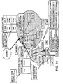
Figs. 10 and11 , it is assumed that connections between the DEVs-B (#3 and #4) and thePNC 100 are disconnected, for example.- 2-1) The DEV-
B 124 with #4 that does not require a static connection closes its connection as defined in IEEE 802.15.3. - 2-2) The DEV-
B 122 with #3 that requires a static connection is connected to the DEV-A 112 which is an alternative PICONET (child PICONET managed by #1). - 2-3) The DEV-A (#1) 112
registers IP# 3 in (a) switching table included in #1. - 2-4) The DEV-A (#1) 112 notifies the PNC (#0) 100 that #3 is connected to the DEV-A (#1) 112 as an alterative path (a process of this notification by #0 is asynchronous).
- 2-5) The
PNC 100 having detected the disconnection from #3 and #4 deletes information on #3 and #4 from (b) switching table (Fig. 10 ). - 2-6) When a LAN packet destined for #3 arrives, the
PNC 100 broadcasts the LAN packet throughout the PICONET. - 2-7) The DEV-A (#1) receives the LAN packet and transmits the LAN packet to #3 registered in the switching table of #1.
- 2-8) The DEV-B (#3) send/receives the LAN packet through an alternative route of #0<->#1<->#3.
- 2-1) The DEV-
- (3) When a process by #1 in the above 2-4) ends, information indicating that data to #3 is transmitted via #1 (DEV#1) is registered in (b) switching table (
Fig. 11 ) of the PNC (#0) 100. After this, when a LAN packet destined for #3 arrives, thePNC 100 unicasts the LAN packet to the DEV-A (#1). - In
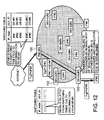
Fig. 12 , the DEV-B (#3) 122 using the alternative route monitors resumption of a beacon from thePNC 100. When a beacon is resumed by removal of the obstacle, for example, the connection of the DEV-B (#3) 122 to thePNC 100 reverts. The contents of the switching tables of thePNC 100 and the DEV-A (#1) 112 are reset to normal and transmission and reception of a LAN packet using the original route are performed. - For a method for recognizing, in a wireless layer, occurrence of failure in a wireless portion and alerting notified failure, first, whether a connection request by each DEV is static or ad hoc is managed using a connection table. When a situation different from a normal one occurs, the PNC or a DEV provides a notification. The notification is performed by an email, sound, phone call, or the like. Information that a notification is being provided is entered in and managed by the connection table.
- A PNC of the present invention operates as a PC based dedicated device, for example, by SW which operates thereon. A DEV-A of the present invention is installed in a room, for example, so as to be seen from a plurality of DEVs-B and the PNC (in a wirelessly communicable manner).
A DEV-A is provided as a box-type device having an Eth/millimeter-wave interface, for example. Such a device can incorporate embedded software (SW) for implementing a method of the present invention. The device is operated based on some kind of embedded OS and functions as a driver for operating hardware (HW) of the Eth/millimeter-wave interface included in the device. - When a DEV-B of the present invention is a terminal personal computer (PC), for example, the DEV-B is operated by software which is supplied with a millimeter-wave wireless LAN card. Alternatively, when the DEV-B is an external device (when the DEV-B is a LAN-compatible security device or household electrical appliance which cannot expand a card as in a PC), the DEV-B is operated by embedded SW which operates in a box-type device, as with the DEV-A.
- The present invention has been described with reference to the drawings. However, the present invention is not limited to the above-described embodiment. It will be obvious to those skilled in the art that modifications may be made to the embodiment without departing from the spirit and scope of the present invention.
-
-
Fig. 1 is a diagram showing a basic configuration of a LAN packet communication system using a normal PICONET, according to the present invention; -
Fig. 2 is a diagram showing a system configuration in the present invention; -
Fig. 3 is a diagram showing a system configuration (before occurrence of failure) in the present invention; -
Fig. 4 is a diagram showing a system configuration (immediately after occurrence of failure) in the present invention; -
Fig. 5 is a diagram showing a system configuration (a state showing securing of an alternative route after occurrence of failure) in the present invention; -
Fig. 6 is a diagram showing a switching table and a connection table which are included in a PNC; -
Fig. 7 is a diagram showing a table for the case in which a DEV-B (#5) inFig. 2 is registered asIP# 5; -
Fig. 8 is a diagram showing a table for the case in which a DEV-B (#4) inFig. 2 is registered asIP# 4; -
Fig. 9 is a diagram showing a state in which, after #4 inFig. 8 is recognized, DEVs-B with #3 and #6 are further connected; -
Fig. 10 is a diagram showing a state in which connections between the DEVs-B (#3 and #4) and the PNC are disconnected; -
Fig. 11 is a diagram showing a state in which a connection between the DEV-B (#3) and the PNC is secured by an alternative route via a DEV-A (#1); and -
Fig. 12 is a diagram showing a state in which the interference is removed and the original connection between the DEV-B (#3) and the PNC is recovered. -
- 10 and 100:
- PNC
- 20:
- DEV
- 30:
- WIRELESS ROUTE
- 110, 112, and 114:
- DEV-A (ALTERNATIVE PNC)
- 120, 122, and 124:
- DEV-B
- 200:
- OBSTACLE
Claims (10)
- A wireless local area network (LAN) system comprising:a relay which can communicate with an external system;a master which can communicate with the relay; anda plurality of slaves which can wirelessly communicate with the master, the plurality of slaves including a first group and a second group, the first group comprising alternative slaves having a function of transmitting, when a portion of the slaves cannot receive a synchronization signal from the master, an information signal received from the master to the portion of slaves, and the second group including non-alternative slaves not having the function of transmitting the information signal to the portion of slaves.
- The wireless LAN system according to claim 1, wherein the second group includes ad-hoc slaves.
- The wireless LAN system according to claim 1, wherein the slave of the first group can send a synchronization signal and transmit the information signal received from the master to the non-alternative slaves that can receive the synchronization signal.
- The wireless LAN system according to claim 1, wherein the relay communicates with the external system through light and communicates with the master and the slaves through millimeter waves.
- The wireless LAN system according to any one of claims 1 to 4, wherein the master has a first table and the first table includes a list of communicable slaves.
- The wireless LAN system according to claim 5, wherein the slave of the first group has a second table and the second table includes a list of communicable slaves of the second group.
- The wireless LAN system according to claim 1, wherein because of presence of an obstacle between the master and the portion of slaves, the portion of slaves cannot receive a synchronization signal from the master.
- A wireless communication method between a master and a plurality of slaves which are included in a wireless local area network (LAN) system, comprising the steps of:transmitting a first synchronization signal to the plurality of slaves from the master;transmitting a first received signal to the master from a slave having received the first synchronization signal;sending a second synchronization signal from a specific slave among the plurality of slaves to other slaves;transmitting a second received signal to the specific slave from slaves having received the second synchronization signals;transmitting an information signal to the specific slave from the master; andtransmitting the information signal from the specific slave to a slave not having sent a first received signal among the slaves having received the second synchronization signals.
- A wireless communication method for performing wireless communication between a master and a plurality of slaves which are included in a wireless local area network (LAN) system, the master performing the steps of:transmitting a first synchronization signal to the plurality of slaves;receiving a first received signal from a slave having received the first synchronization signal;detecting a slave not having sent a first received signal;transmitting an instruction signal to a specific slave among the plurality of slaves to urge the specific slave to send a second synchronization signal;receiving from the specific slave a second received signal indicating that the slave that had not sent the first received signal has received the second synchronization signal; andtransmitting to the specific slave an information signal for the slave having received the second synchronization signal and not having sent the first received signal.
- A wireless communication method for performing wireless communication between a master and a plurality of slaves which are included in a wireless local area network (LAN) system, a portion of slaves among the plurality of slaves performing the steps of:sending a first synchronization signal;receiving a first received signal from a slave having received the first synchronization signal;transmitting to the master a signal indicating that the slave has received the first synchronization signal; andreceiving from the master an information signal for the slave having received the first synchronization signal.
Applications Claiming Priority (2)
| Application Number | Priority Date | Filing Date | Title |
|---|---|---|---|
| JP2007123906 | 2007-05-08 | ||
| PCT/JP2008/057532 WO2008139830A1 (en) | 2007-05-08 | 2008-04-17 | Radio local area network (lan) system |
Publications (2)
| Publication Number | Publication Date |
|---|---|
| EP2157740A1 true EP2157740A1 (en) | 2010-02-24 |
| EP2157740A4 EP2157740A4 (en) | 2014-01-22 |
Family
ID=40002049
Family Applications (1)
| Application Number | Title | Priority Date | Filing Date |
|---|---|---|---|
| EP08740594.0A Withdrawn EP2157740A4 (en) | 2007-05-08 | 2008-04-17 | Radio local area network (lan) system |
Country Status (8)
| Country | Link |
|---|---|
| US (2) | US8488496B2 (en) |
| EP (1) | EP2157740A4 (en) |
| JP (1) | JP5039928B2 (en) |
| KR (1) | KR101038897B1 (en) |
| CN (1) | CN101682930B (en) |
| BR (1) | BRPI0810275B1 (en) |
| TW (1) | TWI444008B (en) |
| WO (1) | WO2008139830A1 (en) |
Cited By (2)
| Publication number | Priority date | Publication date | Assignee | Title |
|---|---|---|---|---|
| WO2010065176A1 (en) | 2008-12-01 | 2010-06-10 | Motorola, Inc. | Method and apparatus for establishing a call in a digital radio communication system |
| CN108990107A (en) * | 2017-06-02 | 2018-12-11 | 华为技术有限公司 | Data transmission method and equipment |
Families Citing this family (11)
| Publication number | Priority date | Publication date | Assignee | Title |
|---|---|---|---|---|
| KR101563195B1 (en) | 2009-08-18 | 2015-10-27 | 삼성전자주식회사 | Host device and slave device controlling method |
| US8472437B2 (en) * | 2010-02-15 | 2013-06-25 | Texas Instruments Incorporated | Wireless chip-to-chip switching |
| CN103201965A (en) * | 2010-10-27 | 2013-07-10 | 松下电器产业株式会社 | Wireless communication device and wireless communication method |
| EP3050332B1 (en) | 2013-09-27 | 2019-02-06 | Koninklijke KPN N.V. | Public safety system |
| JP6390126B2 (en) * | 2014-03-14 | 2018-09-19 | 株式会社リコー | Information processing system, information processing apparatus, information processing method, and program |
| KR101590272B1 (en) * | 2014-12-31 | 2016-01-29 | 엘에스산전 주식회사 | Message processing unit of PLC System |
| US10015744B2 (en) * | 2015-01-05 | 2018-07-03 | Qualcomm Incorporated | Low power operations in a wireless tunneling transceiver |
| JP6520766B2 (en) | 2016-03-09 | 2019-05-29 | オムロン株式会社 | Wireless communication apparatus, wireless information collection system, and wireless communication method |
| CN109831815B (en) * | 2018-12-14 | 2021-10-08 | 中磊电子股份有限公司 | Data transmission coordination system and method thereof |
| JP7287325B2 (en) * | 2020-03-26 | 2023-06-06 | 横河電機株式会社 | CONTROL SYSTEMS, CONTROLLERS AND METHODS OF ACCESSING FIELD DEVICES |
| CN116419320A (en) * | 2021-12-29 | 2023-07-11 | 中国联合网络通信集团有限公司 | Communication method, device and storage medium |
Family Cites Families (19)
| Publication number | Priority date | Publication date | Assignee | Title |
|---|---|---|---|---|
| US7023833B1 (en) * | 1999-09-10 | 2006-04-04 | Pulse-Link, Inc. | Baseband wireless network for isochronous communication |
| US20020044549A1 (en) * | 2000-06-12 | 2002-04-18 | Per Johansson | Efficient scatternet forming |
| US6934554B2 (en) * | 2001-02-21 | 2005-08-23 | Nippon Telegraph And Telephone Corporation | Radio communication system |
| JP3858746B2 (en) * | 2001-05-08 | 2006-12-20 | ソニー株式会社 | Wireless communication system, wireless communication control device, wireless communication control method, and computer program |
| US20030179722A1 (en) * | 2001-05-14 | 2003-09-25 | Sunao Takatori | Master communication apparatus used in radio lan system, and control method and control program of master communication apparatus |
| CN1711720A (en) * | 2002-10-17 | 2005-12-21 | 松下电器产业株式会社 | Wireless communication system |
| JP4618989B2 (en) | 2003-02-18 | 2011-01-26 | 三菱電機株式会社 | Magnetic memory semiconductor device |
| KR100518795B1 (en) | 2003-03-13 | 2005-10-05 | 삼성전자주식회사 | Re-synchronization method for ad-hoc network environment |
| US7668124B2 (en) * | 2003-05-21 | 2010-02-23 | Broadcom Corporation | Position based WPAN (Wireless Personal Area Network) management |
| ES2294539T3 (en) * | 2003-08-06 | 2008-04-01 | Matsushita Electric Industrial Co., Ltd | MAIN STATION OF COMMUNICATION SYSTEM, AND ACCESS CONTROL METHOD. |
| JPWO2005034434A1 (en) | 2003-10-03 | 2007-11-22 | シャープ株式会社 | COMMUNICATION DEVICE, OPERATION MODE STARTING METHOD FOR THE DEVICE, COMMUNICATION METHOD, COMMUNICATION SYSTEM, PROGRAM, AND RECORDING MEDIUM CONTAINING THE PROGRAM |
| KR100547849B1 (en) * | 2003-12-05 | 2006-01-31 | 삼성전자주식회사 | Frame Structure for Selecting Bridge Device in WPAN and Method for Selecting Bridge Device in WPAN |
| US7460503B2 (en) * | 2004-02-03 | 2008-12-02 | Sharp Laboratories Of America, Inc. | Method for beacon rebroadcast in centrally controlled wireless systems |
| JP4214960B2 (en) * | 2004-06-24 | 2009-01-28 | 株式会社日立製作所 | Wireless communication network system |
| KR100582727B1 (en) * | 2004-12-08 | 2006-05-22 | 삼성전자주식회사 | Wireless LAN transmission power control system and method |
| JP2006287477A (en) | 2005-03-31 | 2006-10-19 | Advanced Telecommunication Research Institute International | Wireless device |
| JP4662353B2 (en) * | 2005-08-12 | 2011-03-30 | キヤノン株式会社 | Communication system, communication apparatus, communication control device, control program, and control method |
| KR100725418B1 (en) * | 2006-01-05 | 2007-06-07 | 삼성전자주식회사 | How to Find a Wireless Communication Device and Wireless Communication Device |
| US8457553B2 (en) * | 2007-03-22 | 2013-06-04 | Qualcomm Incorporated | Removal of ambiguities in forming new piconet controller (PNC) when the current PNC controller is suddenly unavailable |
-
2008
- 2008-04-17 CN CN2008800146684A patent/CN101682930B/en not_active Expired - Fee Related
- 2008-04-17 KR KR1020097018354A patent/KR101038897B1/en not_active Expired - Fee Related
- 2008-04-17 JP JP2009514050A patent/JP5039928B2/en not_active Expired - Fee Related
- 2008-04-17 US US12/599,104 patent/US8488496B2/en not_active Expired - Fee Related
- 2008-04-17 BR BRPI0810275-9A patent/BRPI0810275B1/en active IP Right Grant
- 2008-04-17 WO PCT/JP2008/057532 patent/WO2008139830A1/en not_active Ceased
- 2008-04-17 EP EP08740594.0A patent/EP2157740A4/en not_active Withdrawn
- 2008-05-02 TW TW097116338A patent/TWI444008B/en not_active IP Right Cessation
-
2013
- 2013-03-11 US US13/794,087 patent/US8873434B2/en not_active Expired - Fee Related
Cited By (4)
| Publication number | Priority date | Publication date | Assignee | Title |
|---|---|---|---|---|
| WO2010065176A1 (en) | 2008-12-01 | 2010-06-10 | Motorola, Inc. | Method and apparatus for establishing a call in a digital radio communication system |
| EP2371177A4 (en) * | 2008-12-01 | 2012-12-12 | Motorola Solutions Inc | METHOD AND APPARATUS FOR ESTABLISHING COMMUNICATION IN A DIGITAL RADIOCOMMUNICATION SYSTEM |
| CN108990107A (en) * | 2017-06-02 | 2018-12-11 | 华为技术有限公司 | Data transmission method and equipment |
| CN108990107B (en) * | 2017-06-02 | 2021-06-22 | 华为技术有限公司 | Data transmission method and equipment |
Also Published As
| Publication number | Publication date |
|---|---|
| BRPI0810275B1 (en) | 2020-03-31 |
| US8488496B2 (en) | 2013-07-16 |
| BRPI0810275A2 (en) | 2017-06-06 |
| WO2008139830A1 (en) | 2008-11-20 |
| US20130195094A1 (en) | 2013-08-01 |
| CN101682930A (en) | 2010-03-24 |
| US20100214999A1 (en) | 2010-08-26 |
| JPWO2008139830A1 (en) | 2010-07-29 |
| EP2157740A4 (en) | 2014-01-22 |
| US8873434B2 (en) | 2014-10-28 |
| CN101682930B (en) | 2012-11-14 |
| JP5039928B2 (en) | 2012-10-03 |
| TWI444008B (en) | 2014-07-01 |
| KR101038897B1 (en) | 2011-06-07 |
| TW200910835A (en) | 2009-03-01 |
| KR20090114434A (en) | 2009-11-03 |
Similar Documents
| Publication | Publication Date | Title |
|---|---|---|
| US8488496B2 (en) | Wireless local area network (LAN) system | |
| EP2312903B1 (en) | Method and apparatus for peer-to-peer connection using wireless local area network (LAN) in mobile communication terminal | |
| JP3461493B2 (en) | Network system and relay station device | |
| JP3104514B2 (en) | Delivery procedure for mobile wireless station | |
| JP3382806B2 (en) | Slave station | |
| US10555371B2 (en) | Devices and methods for multi bearer network communication | |
| US20130148556A1 (en) | System And Method For Access Point Power Save | |
| CA2376595A1 (en) | A communications device | |
| EP2282583A1 (en) | Wireless access point implementing variable beacon transmission intervals | |
| JP2002359864A (en) | Method for switching attribute of mobile terminal station to base station | |
| US8159937B2 (en) | Seamless tree creation and movement | |
| CN105404253B (en) | A control command sending method, response method and device | |
| WO2009037624A2 (en) | Multiple connection wireless interface | |
| CN101237682A (en) | Wireless network system and its connection method | |
| JPWO2006075402A1 (en) | Open loop network node device and open loop network control method | |
| CN102802237A (en) | Data forwarding control method and wireless centralized control equipment | |
| EP4531459A1 (en) | Communication device, mobile communication system, control method, and program | |
| US20020126665A1 (en) | Wireless lan system and method for the same | |
| JP2025146084A (en) | Communication device, communication method, and program | |
| EP1239631A2 (en) | Wireless LAN system and method for seamless communications of a mobile terminal | |
| JPWO2011013705A1 (en) | Monitoring control device and monitoring target device | |
| JP3841099B2 (en) | Mobile communication method and mobile communication system | |
| JP2004214952A (en) | Communication system and communication device | |
| JP5593216B2 (en) | Wireless device | |
| KR20060106777A (en) | Method and apparatus for determining involvement level of mesh point in wireless communication system |
Legal Events
| Date | Code | Title | Description |
|---|---|---|---|
| PUAI | Public reference made under article 153(3) epc to a published international application that has entered the european phase |
Free format text: ORIGINAL CODE: 0009012 |
|
| 17P | Request for examination filed |
Effective date: 20091112 |
|
| AK | Designated contracting states |
Kind code of ref document: A1 Designated state(s): AT BE BG CH CY CZ DE DK EE ES FI FR GB GR HR HU IE IS IT LI LT LU LV MC MT NL NO PL PT RO SE SI SK TR |
|
| AX | Request for extension of the european patent |
Extension state: AL BA MK RS |
|
| DAX | Request for extension of the european patent (deleted) | ||
| A4 | Supplementary search report drawn up and despatched |
Effective date: 20140102 |
|
| RIC1 | Information provided on ipc code assigned before grant |
Ipc: H04W 40/34 20090101AFI20131217BHEP Ipc: H04W 84/20 20090101ALI20131217BHEP |
|
| STAA | Information on the status of an ep patent application or granted ep patent |
Free format text: STATUS: THE APPLICATION HAS BEEN WITHDRAWN |
|
| 18W | Application withdrawn |
Effective date: 20140620 |