EP2157681A2 - Direct flux regulated permanent magnet brushless motor utilizing sensorless control by dc and ac excitation - Google Patents
Direct flux regulated permanent magnet brushless motor utilizing sensorless control by dc and ac excitation Download PDFInfo
- Publication number
- EP2157681A2 EP2157681A2 EP09252027A EP09252027A EP2157681A2 EP 2157681 A2 EP2157681 A2 EP 2157681A2 EP 09252027 A EP09252027 A EP 09252027A EP 09252027 A EP09252027 A EP 09252027A EP 2157681 A2 EP2157681 A2 EP 2157681A2
- Authority
- EP
- European Patent Office
- Prior art keywords
- permanent magnet
- stator
- control
- motor
- current
- Prior art date
- Legal status (The legal status is an assumption and is not a legal conclusion. Google has not performed a legal analysis and makes no representation as to the accuracy of the status listed.)
- Granted
Links
Images


Classifications
-
- H—ELECTRICITY
- H02—GENERATION; CONVERSION OR DISTRIBUTION OF ELECTRIC POWER
- H02K—DYNAMO-ELECTRIC MACHINES
- H02K21/00—Synchronous motors having permanent magnets; Synchronous generators having permanent magnets
- H02K21/12—Synchronous motors having permanent magnets; Synchronous generators having permanent magnets with stationary armatures and rotating magnets
-
- H—ELECTRICITY
- H02—GENERATION; CONVERSION OR DISTRIBUTION OF ELECTRIC POWER
- H02K—DYNAMO-ELECTRIC MACHINES
- H02K29/00—Motors or generators having non-mechanical commutating devices, e.g. discharge tubes or semiconductor devices
- H02K29/06—Motors or generators having non-mechanical commutating devices, e.g. discharge tubes or semiconductor devices with position sensing devices
- H02K29/12—Motors or generators having non-mechanical commutating devices, e.g. discharge tubes or semiconductor devices with position sensing devices using detecting coils using the machine windings as detecting coil
-
- H—ELECTRICITY
- H02—GENERATION; CONVERSION OR DISTRIBUTION OF ELECTRIC POWER
- H02K—DYNAMO-ELECTRIC MACHINES
- H02K3/00—Details of windings
- H02K3/46—Fastening of windings on the stator or rotor structure
- H02K3/48—Fastening of windings on the stator or rotor structure in slots
- H02K3/487—Slot-closing devices
- H02K3/493—Slot-closing devices magnetic
-
- H—ELECTRICITY
- H02—GENERATION; CONVERSION OR DISTRIBUTION OF ELECTRIC POWER
- H02P—CONTROL OR REGULATION OF ELECTRIC MOTORS, ELECTRIC GENERATORS OR DYNAMO-ELECTRIC CONVERTERS; CONTROLLING TRANSFORMERS, REACTORS OR CHOKE COILS
- H02P6/00—Arrangements for controlling synchronous motors or other dynamo-electric motors using electronic commutation dependent on the rotor position; Electronic commutators therefor
- H02P6/14—Electronic commutators
- H02P6/16—Circuit arrangements for detecting position
- H02P6/18—Circuit arrangements for detecting position without separate position detecting elements
- H02P6/183—Circuit arrangements for detecting position without separate position detecting elements using an injected high frequency signal
-
- H—ELECTRICITY
- H02—GENERATION; CONVERSION OR DISTRIBUTION OF ELECTRIC POWER
- H02P—CONTROL OR REGULATION OF ELECTRIC MOTORS, ELECTRIC GENERATORS OR DYNAMO-ELECTRIC CONVERTERS; CONTROLLING TRANSFORMERS, REACTORS OR CHOKE COILS
- H02P6/00—Arrangements for controlling synchronous motors or other dynamo-electric motors using electronic commutation dependent on the rotor position; Electronic commutators therefor
- H02P6/14—Electronic commutators
- H02P6/16—Circuit arrangements for detecting position
- H02P6/18—Circuit arrangements for detecting position without separate position detecting elements
- H02P6/185—Circuit arrangements for detecting position without separate position detecting elements using inductance sensing, e.g. pulse excitation
-
- H—ELECTRICITY
- H02—GENERATION; CONVERSION OR DISTRIBUTION OF ELECTRIC POWER
- H02P—CONTROL OR REGULATION OF ELECTRIC MOTORS, ELECTRIC GENERATORS OR DYNAMO-ELECTRIC CONVERTERS; CONTROLLING TRANSFORMERS, REACTORS OR CHOKE COILS
- H02P2203/00—Indexing scheme relating to controlling arrangements characterised by the means for detecting the position of the rotor
- H02P2203/11—Determination or estimation of the rotor position or other motor parameters based on the analysis of high-frequency signals
Definitions
- This application relates to a permanent magnet flux regulated motor, wherein no sensor is necessary to provide position feedback of the location of the rotor.
- stator may include slots which are closed by ferromagnetic wedges.
- the wedges are provided with control coils fed with current. By controlling the current through the control coils, the overall magnetic flux can be controlled.
- a sensor could be provided; however, a sensor would add to the cost and weight.
- Another method of sensorless control is to sense the inductance variation along the quadrature and direct axes, known as the d and q axes.
- the direct axis is the center axis of the poles of the permanent magnets, while the quadrature axis is shifted by 45°.
- EP09251090.8 discloses such a method.
- a flux regulated permanent magnet brushless motor has a stator having an inner peripheral bore.
- a permanent magnet rotor is mounted within the inner peripheral bore.
- a control winding is supplied with a DC current to regulate flux of the machine.
- An AC current is also supplied and an output is sensed to determine a position of the permanent magnet rotor.
- a rotor 21, shown as a cutaway in Figure 1 is a permanent magnetic rotor, and the stator 20 is slotted. Stator slots are provided with stator coils.
- the electromagnetic wedges 22 are provided with control coils 24.
- the control coils may receive a DC or an AC current.
- the coils 24 may be connected in series to create a control winding. In a disclosed embodiment of this invention, the control coils receive a DC current.
- the electromagnetic wedges 22 behave as shunts for a magnetic flux produced by the permanent magnet motor. If the reluctance of the wedges is low, a portion of the magnetic flux is shunted by the wedges.
- Figure 1 shows a stator with double layer AC winding distributed in slots closed with wedges 22 (magnetic flux diverters). The stator AC winding can also be made as a single layer winding. Stator teeth 23 are positioned between the slots with AC windings.
- the wedges 22 may be made of laminated ferromagnetic alloys or sintered magnetic powders.
- the magnetic wedges with the control coils can be inserted directly into conventional stator slots.
- the control coils 24 can also be wound with rectangular conductors or foil conductors ( Figure 3B ).
- slot wedges can be stamped together with the stator teeth and after inserting the stator windings into the slots, a wound star-shaped stator core can be pressed into a ring-shaped stator ferromagnetic yoke.
- the reluctance of a ferromagnetic material is inversely proportional to its magnetic permeability. If the control current in the control coils 24 is zero, the reluctance of the magnetic shunt provided by the wedges 22 is low because their magnetic permeability is high. Almost the total air gap magnetic flux produced by the permanent magnets will pass through the slot wedges.
- the electromagnetic torque can be controlled as well as the EMF.
- the rotor magnetic flux can induce some AC voltage in the control winding. This voltage can be cancelled by connecting the same terminals (i.e., beginning with beginning and end with end of neighboring shunt coils). Such connection can typically only be done with DC control current.
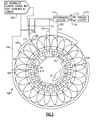
- FIG 2 shows an AC control circuit 100 that with the stator control coils 24 illustrated in Figure 1 provides position feedback. Only some of the control coils 24 are numbered, but it should be understood that each of the other locations illustrates a similar coil 24.
- a DC controlled current source 102 supplies the DC current to the control coils 24 as mentioned above.
- a high frequency AC current is added.
- a 100 kHz oscillation can be applied to the control coils.
- the source 102 supplies the current through connections 104 (terminal S2), 105 (terminal S1) and to branch lines 108 to separate sets of the coils 24.
- Stator control coils 24 are in turn connected by jumper lines 110 such that there are distinct sets of stator coils 24 associated with each of the four branch lines 108. As illustrated, there are equal numbers of coils in each of the sets.
- Connections 106 (terminal CT1) and 109 (terminal CT2) communicate back to a synchronous detector 114. The magnitude of the AC signals at the terminals CT1 and CT2 varies as a function of the rotor magnets position.
- the synchronous detector 114 provides selection of these signals and delivers both a cosine 118 and sine 116 signals as a function of rotor angle. These quadrature components of the rotating vector are processed by a position decoder 119.
- the sine and cosine function provide the position detector 119 with the ability to detect the position of the permanent magnet rotor 21 (again shown in cutaway in Figure 2 ) relative to the stator.
- control coils 24 are connected in series into their four groups. That is, supply 106 communicates with two groups and supply line 104 communicates with two groups, each through branch line 108. Of course, other numbers of groups and other numbers of coils within each group would come within the scope of this invention.
- Control coils of this embodiment do not require any special shape for the stator core, and need not be wound on salient poles. Instead, the control coils can be simply wound on a ferromagnetic wedge and inserted into stator slots.
- the AC and DC control signal is low, and in the range of mA, and the cross-section of the control coil conductors can be small also.
- the stator slot space occupied by the armature winding is not reduced significantly.
- the present disclosed embodiment will enable position detection either with or without the applied DC excitation, e.g., during a windmilling engine start.
- control coil 126 wrapped around the wedge 124 can be round wire.
- Figure 3B shows an embodiment 127 wherein foil ribbon 128 is utilized for the control coil.
Landscapes
- Engineering & Computer Science (AREA)
- Power Engineering (AREA)
- Control Of Motors That Do Not Use Commutators (AREA)
- Brushless Motors (AREA)
Abstract
Description
- This application relates to a permanent magnet flux regulated motor, wherein no sensor is necessary to provide position feedback of the location of the rotor.
- In the field of electric motors, permanent magnet motors are known, as are motors utilizing coils for their rotors. Recently, a permanent magnet brushless motor design has been developed, which uses direct flux regulation to provide better control. The stator may include slots which are closed by ferromagnetic wedges. The wedges are provided with control coils fed with current. By controlling the current through the control coils, the overall magnetic flux can be controlled.
- To use the overall control of magnetic flux, precise position feedback for the permanent magnet rotor is required. A sensor could be provided; however, a sensor would add to the cost and weight.
- Various sensorless control techniques are known, such as detection of back EMF, detection of the stator third harmonic voltage, and detection of the conducting interval of free-wheeling diodes connected in antiparallel with solid state switches.
- Another method of sensorless control is to sense the inductance variation along the quadrature and direct axes, known as the d and q axes. The direct axis is the center axis of the poles of the permanent magnets, while the quadrature axis is shifted by 45°.
EP09251090.8 - A flux regulated permanent magnet brushless motor has a stator having an inner peripheral bore. A permanent magnet rotor is mounted within the inner peripheral bore. A control winding is supplied with a DC current to regulate flux of the machine. An AC current is also supplied and an output is sensed to determine a position of the permanent magnet rotor.
- These and other features of the present invention can be best understood from the following specification and drawings, the following of which is a brief description.
-
-
Figure 1 is a partial cross-sectional view through a stator of a known motor. -
Figure 2 shows a control circuitry that is added onto the motor stator ofFigure 1 . -
Figure 3A shows a first control coil. -
Figure 3B shows a second control coil. - As shown in
Figure 1 , in a known permanent magnet brushless motor, direct regulation of the magnetic flux is provided. Arotor 21, shown as a cutaway inFigure 1 , is a permanent magnetic rotor, and thestator 20 is slotted. Stator slots are provided with stator coils. Theelectromagnetic wedges 22 are provided withcontrol coils 24. The control coils may receive a DC or an AC current. Thecoils 24 may be connected in series to create a control winding. In a disclosed embodiment of this invention, the control coils receive a DC current. - The
electromagnetic wedges 22 behave as shunts for a magnetic flux produced by the permanent magnet motor. If the reluctance of the wedges is low, a portion of the magnetic flux is shunted by the wedges.Figure 1 shows a stator with double layer AC winding distributed in slots closed with wedges 22 (magnetic flux diverters). The stator AC winding can also be made as a single layer winding.Stator teeth 23 are positioned between the slots with AC windings. - The
wedges 22 may be made of laminated ferromagnetic alloys or sintered magnetic powders. The magnetic wedges with the control coils can be inserted directly into conventional stator slots. Instead of round conductors (Figure 3A ), thecontrol coils 24 can also be wound with rectangular conductors or foil conductors (Figure 3B ). Alternatively, slot wedges can be stamped together with the stator teeth and after inserting the stator windings into the slots, a wound star-shaped stator core can be pressed into a ring-shaped stator ferromagnetic yoke. - The reluctance of a ferromagnetic material is inversely proportional to its magnetic permeability. If the control current in the
control coils 24 is zero, the reluctance of the magnetic shunt provided by thewedges 22 is low because their magnetic permeability is high. Almost the total air gap magnetic flux produced by the permanent magnets will pass through the slot wedges. - Conversely, when the control current is greater than zero, the
slot wedges 22 partially saturate and their magnetic permeability decreases. Their reluctance increases and only a portion of the magnetic flux is shunted by the wedges. - As the magnetic flux linked with the stator windings increases, so does the back EMF induced in the stator windings and the electromagnetic torque. Thus, by controlling the control current, the electromagnetic torque can be controlled as well as the EMF.
- Increasing the control current further increases the slot wedge reluctance and its relative magnetic permeability approaches unity. A fully saturated slot wedge behaves as a free space. Almost the whole air gap magnetic flux excited by the rotor permanent magnets will penetrate through the stator teeth and yoke and excites a maximum EMF in the stator winding, and also a maximum electromagnetic torque.
- The rotor magnetic flux can induce some AC voltage in the control winding. This voltage can be cancelled by connecting the same terminals (i.e., beginning with beginning and end with end of neighboring shunt coils). Such connection can typically only be done with DC control current.
- To properly operate the proposed machines as set forth above, precise position feedback of the rotor is necessary.
-
Figure 2 shows anAC control circuit 100 that with thestator control coils 24 illustrated inFigure 1 provides position feedback. Only some of thecontrol coils 24 are numbered, but it should be understood that each of the other locations illustrates asimilar coil 24. A DC controlledcurrent source 102 supplies the DC current to thecontrol coils 24 as mentioned above. - In addition, a high frequency AC current is added. As an example, a 100 kHz oscillation can be applied to the control coils. As illustrated, the
source 102 supplies the current through connections 104 (terminal S2), 105 (terminal S1) and tobranch lines 108 to separate sets of thecoils 24.Stator control coils 24 are in turn connected byjumper lines 110 such that there are distinct sets ofstator coils 24 associated with each of the fourbranch lines 108. As illustrated, there are equal numbers of coils in each of the sets. Connections 106 (terminal CT1) and 109 (terminal CT2) communicate back to asynchronous detector 114. The magnitude of the AC signals at the terminals CT1 and CT2 varies as a function of the rotor magnets position. Thesynchronous detector 114 provides selection of these signals and delivers both acosine 118 andsine 116 signals as a function of rotor angle. These quadrature components of the rotating vector are processed by aposition decoder 119. The sine and cosine function provide theposition detector 119 with the ability to detect the position of the permanent magnet rotor 21 (again shown in cutaway inFigure 2 ) relative to the stator. - This invention thus provides sensorless operation and precise feedback on the exact position of the rotor. As shown in
Figure 2 , the control coils 24 are connected in series into their four groups. That is,supply 106 communicates with two groups andsupply line 104 communicates with two groups, each throughbranch line 108. Of course, other numbers of groups and other numbers of coils within each group would come within the scope of this invention. - Control coils of this embodiment do not require any special shape for the stator core, and need not be wound on salient poles. Instead, the control coils can be simply wound on a ferromagnetic wedge and inserted into stator slots.
- The AC and DC control signal is low, and in the range of mA, and the cross-section of the control coil conductors can be small also. Thus, the stator slot space occupied by the armature winding is not reduced significantly. Further, the present disclosed embodiment will enable position detection either with or without the applied DC excitation, e.g., during a windmilling engine start.
- As shown in
Figure 3A , in oneembodiment 120, thecontrol coil 126 wrapped around thewedge 124 can be round wire. As another alternative,Figure 3B shows anembodiment 127 whereinfoil ribbon 128 is utilized for the control coil. - Although an embodiment of this invention has been disclosed, a worker of ordinary skill in this art would recognize that certain modifications would come within the scope of this invention. For that reason, the following claims should be studied to determine the true scope and content of this invention.
Claims (6)
- A flux regulated permanent magnet brushless motor comprising:a stator (20) having an inner peripheral bore;a permanent magnet rotor (21) mounted within said inner peripheral bore;a control coil (24) to regulate flux of the machine; andwherein a DC current is supplied to the control coil, and a small AC current is also supplied and a responsive signal is detected to determine a position of the permanent magnet rotor.
- The motor as set forth in claim 1, wherein said stator is a hybrid-type stator with radial outer stator wedges, and said control coils (24) being radial inner control coils, with said control coils being provided with AC and variable DC currents.
- The motor as set forth in claim 1 or 2, wherein a power source connects the AC current to sets of said control coils (24).
- The motor as set forth in claim 3, wherein there are an equal number of control coils (24) in each of said sets.
- The motor as set forth in claim 1, 2, 3 or 4, wherein the responsive signal comes from a pair of connections (106, 109) connected to a synchronous detector (114).
- The motor as set forth in claim 5, wherein said synchronous detector (114) supplies both a sine and a cosine signal to a position decoder (119), and said position decoder in turn determines the rotor position.
Applications Claiming Priority (1)
| Application Number | Priority Date | Filing Date | Title |
|---|---|---|---|
| US12/194,747 US8080960B2 (en) | 2008-08-20 | 2008-08-20 | Direct flux regulated permanent magnet brushless motor utilizing sensorless control by DC and AC excitation |
Publications (3)
| Publication Number | Publication Date |
|---|---|
| EP2157681A2 true EP2157681A2 (en) | 2010-02-24 |
| EP2157681A3 EP2157681A3 (en) | 2013-04-03 |
| EP2157681B1 EP2157681B1 (en) | 2015-06-10 |
Family
ID=41401658
Family Applications (1)
| Application Number | Title | Priority Date | Filing Date |
|---|---|---|---|
| EP09252027.9A Active EP2157681B1 (en) | 2008-08-20 | 2009-08-20 | Direct flux regulated permanent magnet brushless motor utilizing sensorless control by dc and ac excitation |
Country Status (2)
| Country | Link |
|---|---|
| US (1) | US8080960B2 (en) |
| EP (1) | EP2157681B1 (en) |
Cited By (3)
| Publication number | Priority date | Publication date | Assignee | Title |
|---|---|---|---|---|
| EP2573907A3 (en) * | 2011-09-20 | 2016-06-15 | Hamilton Sundstrand Corporation | Method of fabrication of permanent magnet machines with magnetic flux regulation |
| WO2016123638A1 (en) * | 2015-01-28 | 2016-08-04 | Johannes Van Der Merwe Jacobus | Efficient electric generator |
| EP3316459A1 (en) * | 2016-10-26 | 2018-05-02 | Hamilton Sundstrand Corporation | Electric motors |
Families Citing this family (6)
| Publication number | Priority date | Publication date | Assignee | Title |
|---|---|---|---|---|
| DE102009061032A1 (en) * | 2009-05-15 | 2010-11-18 | Tyco Electronics Belgium Ec Bvba | Magnetoelectronic angle sensor, in particular reluctance resolver |
| US8610452B2 (en) * | 2010-04-23 | 2013-12-17 | Korea University Research And Business Foundation | Apparatus and method for diagnosing permanent magnet demagnetization of permanent magnet synchronous motor, and apparatus for driving permanent magnet synchronous motor |
| DE102010062316A1 (en) | 2010-12-02 | 2012-06-06 | Siemens Aktiengesellschaft | Device for determining position |
| US9231504B2 (en) | 2012-05-15 | 2016-01-05 | Robert Lyle Fuller | Electrical control system |
| US9287819B2 (en) * | 2013-03-15 | 2016-03-15 | Sky Windpower Corporation | System and method for determining rotor shaft position of high voltage PM AC synchronous machines using auxiliary windings |
| WO2014208103A1 (en) * | 2013-06-27 | 2014-12-31 | Toyo Gosei Co., Ltd. | Reagent for enhancing generation of chemical species |
Citations (4)
| Publication number | Priority date | Publication date | Assignee | Title |
|---|---|---|---|---|
| EP0596682A1 (en) | 1992-11-02 | 1994-05-11 | Seiberco Incorporated | Motor with position sensing |
| JP2000116091A (en) | 1998-09-29 | 2000-04-21 | Hitachi Ltd | Permanent magnet type synchronous motor and elevator apparatus using the same |
| EP1511160A2 (en) | 2003-08-27 | 2005-03-02 | Matsushita Electric Industrial Co., Ltd. | Motor generator |
| US20060097598A1 (en) | 2004-11-05 | 2006-05-11 | Andras Lelkes | Brushless motor |
Family Cites Families (15)
| Publication number | Priority date | Publication date | Assignee | Title |
|---|---|---|---|---|
| DE1291821B (en) * | 1966-08-12 | 1969-04-03 | Siemens Ag | Process for the continuous reversal of the direction of rotation and the motor torque of a brushless direct current motor |
| US3617841A (en) * | 1968-10-31 | 1971-11-02 | Harrison D Brailsford | Self-synchronizing direct current brushless motor |
| DE2527041C3 (en) * | 1975-06-18 | 1979-07-05 | Danfoss A/S, Nordborg (Daenemark) | Independently starting, brushless DC motor |
| JPS5355723A (en) * | 1976-10-30 | 1978-05-20 | Sansui Electric Co | Dc brushless motor |
| JPS61132064A (en) * | 1984-11-29 | 1986-06-19 | Sony Corp | Brushless motor |
| US4687961A (en) | 1986-03-17 | 1987-08-18 | Seiberco Incorporated | Polyphase DC motor with sensor poles |
| US5363032A (en) | 1993-05-12 | 1994-11-08 | Sundstrand Corporation | Sensorless start of synchronous machine |
| JP2943657B2 (en) | 1994-08-02 | 1999-08-30 | トヨタ自動車株式会社 | Control device for salient pole type permanent magnet motor |
| US6058596A (en) | 1998-08-03 | 2000-05-09 | General Electric Company | Method of making an induction motor rotor |
| DE19914943C1 (en) | 1999-04-01 | 2000-08-24 | Daimler Chrysler Ag | Reluctance motor includes internal C-ring, exerting outward radial force to keep especially large coils on stator poles, in rapidly- and simply manufactured design developing more torque, with no efficiency loss |
| US6965183B2 (en) | 2003-05-27 | 2005-11-15 | Pratt & Whitney Canada Corp. | Architecture for electric machine |
| SE527648C2 (en) | 2004-07-09 | 2006-05-02 | Danaher Motion Stockholm Ab | Asynchronous motor with integrated sensor |
| TWI298573B (en) | 2005-02-04 | 2008-07-01 | Foxconn Tech Co Ltd | Sensorless and brushless direct current motor |
| JP4876614B2 (en) * | 2005-06-14 | 2012-02-15 | 日産自動車株式会社 | Rotating electric machine |
| US7508154B1 (en) * | 2006-05-15 | 2009-03-24 | Quicksilver Controls, Inc. | Integrated motor and resolver including absolute position capability |
-
2008
- 2008-08-20 US US12/194,747 patent/US8080960B2/en active Active
-
2009
- 2009-08-20 EP EP09252027.9A patent/EP2157681B1/en active Active
Patent Citations (4)
| Publication number | Priority date | Publication date | Assignee | Title |
|---|---|---|---|---|
| EP0596682A1 (en) | 1992-11-02 | 1994-05-11 | Seiberco Incorporated | Motor with position sensing |
| JP2000116091A (en) | 1998-09-29 | 2000-04-21 | Hitachi Ltd | Permanent magnet type synchronous motor and elevator apparatus using the same |
| EP1511160A2 (en) | 2003-08-27 | 2005-03-02 | Matsushita Electric Industrial Co., Ltd. | Motor generator |
| US20060097598A1 (en) | 2004-11-05 | 2006-05-11 | Andras Lelkes | Brushless motor |
Cited By (4)
| Publication number | Priority date | Publication date | Assignee | Title |
|---|---|---|---|---|
| EP2573907A3 (en) * | 2011-09-20 | 2016-06-15 | Hamilton Sundstrand Corporation | Method of fabrication of permanent magnet machines with magnetic flux regulation |
| WO2016123638A1 (en) * | 2015-01-28 | 2016-08-04 | Johannes Van Der Merwe Jacobus | Efficient electric generator |
| EP3316459A1 (en) * | 2016-10-26 | 2018-05-02 | Hamilton Sundstrand Corporation | Electric motors |
| US10505411B2 (en) | 2016-10-26 | 2019-12-10 | Hamilton Sundstrand Corporation | Electric motors |
Also Published As
| Publication number | Publication date |
|---|---|
| EP2157681A3 (en) | 2013-04-03 |
| US20100045222A1 (en) | 2010-02-25 |
| EP2157681B1 (en) | 2015-06-10 |
| US8080960B2 (en) | 2011-12-20 |
Similar Documents
| Publication | Publication Date | Title |
|---|---|---|
| EP2157681B1 (en) | Direct flux regulated permanent magnet brushless motor utilizing sensorless control by dc and ac excitation | |
| US7843155B2 (en) | Direct flux regulated permanent magnet brushless motor utilizing sensorless control | |
| US9543876B2 (en) | Three phase flux switching generator in a three stage wound field synchronous machine | |
| EP2107665B1 (en) | Permanent magnet dynamoelectric machine with variable magnetic flux excitation | |
| EP2782226B1 (en) | Flux controlled PM electric machine rotor | |
| EP3376650A1 (en) | Permanent magnet starter-generator with magnetic flux regulation | |
| US20100013333A1 (en) | Magnetic radial bearing having permanent-magnet generated magnetic bias, and a magnetic bearing system having a magnetic radial bearing of this type | |
| EP2429063A1 (en) | Ac elelctric machine with claw poles | |
| EP3416268B1 (en) | Three phase flux switching electric machine with orthogonally oriented magnets | |
| EP2139099A2 (en) | Regulated hybrid permanent magnet generator | |
| KR102746892B1 (en) | System and method for preventing permanent magnet demagnetization in electrical machines | |
| US10992190B2 (en) | Self-exciting synchronous reluctance generators | |
| US10505411B2 (en) | Electric motors | |
| WO2001045235A1 (en) | Electronically controlled permanent-magnet electric motor | |
| EP1560317A3 (en) | Brushless exciter with electromagnetically decoupled dual excitation systems for starter-generator applications | |
| US6891301B1 (en) | Simplified hybrid-secondary uncluttered machine and method | |
| EP1798842A1 (en) | Self magnetizing motor and method for winding coils on stator thereof | |
| Singh et al. | Design and analysis of a 3 KVA, 28 V permanent magnet brushless alternator for light combat aircraft | |
| JPH09168271A (en) | Synchronous motor and control method thereof | |
| Rahman et al. | Steady-state performance of polyphase hysteresis-reluctance motors | |
| JPH0515144B2 (en) | ||
| Junak et al. | Comparison of permanent magnet brushless motors designed for Automated Manual Transmission (AMT) systems | |
| JPH07337075A (en) | Permanent magnet electric rotating machine and pole position detecting method therefor | |
| JPH04114763U (en) | Brushless synchronous generator | |
| JPH0636372U (en) | Salient pole self-excited AC generator |
Legal Events
| Date | Code | Title | Description |
|---|---|---|---|
| PUAI | Public reference made under article 153(3) epc to a published international application that has entered the european phase |
Free format text: ORIGINAL CODE: 0009012 |
|
| AK | Designated contracting states |
Kind code of ref document: A2 Designated state(s): AT BE BG CH CY CZ DE DK EE ES FI FR GB GR HR HU IE IS IT LI LT LU LV MC MK MT NL NO PL PT RO SE SI SK SM TR |
|
| AX | Request for extension of the european patent |
Extension state: AL BA RS |
|
| PUAL | Search report despatched |
Free format text: ORIGINAL CODE: 0009013 |
|
| AK | Designated contracting states |
Kind code of ref document: A3 Designated state(s): AT BE BG CH CY CZ DE DK EE ES FI FR GB GR HR HU IE IS IT LI LT LU LV MC MK MT NL NO PL PT RO SE SI SK SM TR |
|
| AX | Request for extension of the european patent |
Extension state: AL BA RS |
|
| RIC1 | Information provided on ipc code assigned before grant |
Ipc: H02K 29/12 20060101ALI20130227BHEP Ipc: H02K 21/04 20060101AFI20130227BHEP |
|
| 17P | Request for examination filed |
Effective date: 20130925 |
|
| RBV | Designated contracting states (corrected) |
Designated state(s): AT BE BG CH CY CZ DE DK EE ES FI FR GB GR HR HU IE IS IT LI LT LU LV MC MK MT NL NO PL PT RO SE SI SK SM TR |
|
| 17Q | First examination report despatched |
Effective date: 20140122 |
|
| GRAP | Despatch of communication of intention to grant a patent |
Free format text: ORIGINAL CODE: EPIDOSNIGR1 |
|
| INTG | Intention to grant announced |
Effective date: 20150227 |
|
| GRAS | Grant fee paid |
Free format text: ORIGINAL CODE: EPIDOSNIGR3 |
|
| GRAA | (expected) grant |
Free format text: ORIGINAL CODE: 0009210 |
|
| AK | Designated contracting states |
Kind code of ref document: B1 Designated state(s): AT BE BG CH CY CZ DE DK EE ES FI FR GB GR HR HU IE IS IT LI LT LU LV MC MK MT NL NO PL PT RO SE SI SK SM TR |
|
| REG | Reference to a national code |
Ref country code: GB Ref legal event code: FG4D |
|
| REG | Reference to a national code |
Ref country code: CH Ref legal event code: EP |
|
| REG | Reference to a national code |
Ref country code: AT Ref legal event code: REF Ref document number: 731259 Country of ref document: AT Kind code of ref document: T Effective date: 20150715 |
|
| REG | Reference to a national code |
Ref country code: DE Ref legal event code: R096 Ref document number: 602009031631 Country of ref document: DE |
|
| REG | Reference to a national code |
Ref country code: IE Ref legal event code: FG4D |
|
| PG25 | Lapsed in a contracting state [announced via postgrant information from national office to epo] |
Ref country code: NO Free format text: LAPSE BECAUSE OF FAILURE TO SUBMIT A TRANSLATION OF THE DESCRIPTION OR TO PAY THE FEE WITHIN THE PRESCRIBED TIME-LIMIT Effective date: 20150910 Ref country code: ES Free format text: LAPSE BECAUSE OF FAILURE TO SUBMIT A TRANSLATION OF THE DESCRIPTION OR TO PAY THE FEE WITHIN THE PRESCRIBED TIME-LIMIT Effective date: 20150610 Ref country code: FI Free format text: LAPSE BECAUSE OF FAILURE TO SUBMIT A TRANSLATION OF THE DESCRIPTION OR TO PAY THE FEE WITHIN THE PRESCRIBED TIME-LIMIT Effective date: 20150610 Ref country code: LT Free format text: LAPSE BECAUSE OF FAILURE TO SUBMIT A TRANSLATION OF THE DESCRIPTION OR TO PAY THE FEE WITHIN THE PRESCRIBED TIME-LIMIT Effective date: 20150610 |
|
| REG | Reference to a national code |
Ref country code: AT Ref legal event code: MK05 Ref document number: 731259 Country of ref document: AT Kind code of ref document: T Effective date: 20150610 |
|
| REG | Reference to a national code |
Ref country code: NL Ref legal event code: MP Effective date: 20150610 |
|
| PG25 | Lapsed in a contracting state [announced via postgrant information from national office to epo] |
Ref country code: LV Free format text: LAPSE BECAUSE OF FAILURE TO SUBMIT A TRANSLATION OF THE DESCRIPTION OR TO PAY THE FEE WITHIN THE PRESCRIBED TIME-LIMIT Effective date: 20150610 Ref country code: GR Free format text: LAPSE BECAUSE OF FAILURE TO SUBMIT A TRANSLATION OF THE DESCRIPTION OR TO PAY THE FEE WITHIN THE PRESCRIBED TIME-LIMIT Effective date: 20150911 Ref country code: BG Free format text: LAPSE BECAUSE OF FAILURE TO SUBMIT A TRANSLATION OF THE DESCRIPTION OR TO PAY THE FEE WITHIN THE PRESCRIBED TIME-LIMIT Effective date: 20150910 |
|
| PG25 | Lapsed in a contracting state [announced via postgrant information from national office to epo] |
Ref country code: EE Free format text: LAPSE BECAUSE OF FAILURE TO SUBMIT A TRANSLATION OF THE DESCRIPTION OR TO PAY THE FEE WITHIN THE PRESCRIBED TIME-LIMIT Effective date: 20150610 |
|
| PG25 | Lapsed in a contracting state [announced via postgrant information from national office to epo] |
Ref country code: IS Free format text: LAPSE BECAUSE OF FAILURE TO SUBMIT A TRANSLATION OF THE DESCRIPTION OR TO PAY THE FEE WITHIN THE PRESCRIBED TIME-LIMIT Effective date: 20151010 Ref country code: SK Free format text: LAPSE BECAUSE OF FAILURE TO SUBMIT A TRANSLATION OF THE DESCRIPTION OR TO PAY THE FEE WITHIN THE PRESCRIBED TIME-LIMIT Effective date: 20150610 Ref country code: RO Free format text: LAPSE BECAUSE OF NON-PAYMENT OF DUE FEES Effective date: 20150610 Ref country code: CZ Free format text: LAPSE BECAUSE OF FAILURE TO SUBMIT A TRANSLATION OF THE DESCRIPTION OR TO PAY THE FEE WITHIN THE PRESCRIBED TIME-LIMIT Effective date: 20150610 Ref country code: PL Free format text: LAPSE BECAUSE OF FAILURE TO SUBMIT A TRANSLATION OF THE DESCRIPTION OR TO PAY THE FEE WITHIN THE PRESCRIBED TIME-LIMIT Effective date: 20150610 Ref country code: AT Free format text: LAPSE BECAUSE OF FAILURE TO SUBMIT A TRANSLATION OF THE DESCRIPTION OR TO PAY THE FEE WITHIN THE PRESCRIBED TIME-LIMIT Effective date: 20150610 Ref country code: PT Free format text: LAPSE BECAUSE OF FAILURE TO SUBMIT A TRANSLATION OF THE DESCRIPTION OR TO PAY THE FEE WITHIN THE PRESCRIBED TIME-LIMIT Effective date: 20151012 |
|
| REG | Reference to a national code |
Ref country code: DE Ref legal event code: R119 Ref document number: 602009031631 Country of ref document: DE |
|
| PG25 | Lapsed in a contracting state [announced via postgrant information from national office to epo] |
Ref country code: LU Free format text: LAPSE BECAUSE OF FAILURE TO SUBMIT A TRANSLATION OF THE DESCRIPTION OR TO PAY THE FEE WITHIN THE PRESCRIBED TIME-LIMIT Effective date: 20150820 Ref country code: MC Free format text: LAPSE BECAUSE OF FAILURE TO SUBMIT A TRANSLATION OF THE DESCRIPTION OR TO PAY THE FEE WITHIN THE PRESCRIBED TIME-LIMIT Effective date: 20150610 |
|
| REG | Reference to a national code |
Ref country code: CH Ref legal event code: PL |
|
| PLBE | No opposition filed within time limit |
Free format text: ORIGINAL CODE: 0009261 |
|
| STAA | Information on the status of an ep patent application or granted ep patent |
Free format text: STATUS: NO OPPOSITION FILED WITHIN TIME LIMIT |
|
| PG25 | Lapsed in a contracting state [announced via postgrant information from national office to epo] |
Ref country code: CH Free format text: LAPSE BECAUSE OF NON-PAYMENT OF DUE FEES Effective date: 20150831 Ref country code: DK Free format text: LAPSE BECAUSE OF FAILURE TO SUBMIT A TRANSLATION OF THE DESCRIPTION OR TO PAY THE FEE WITHIN THE PRESCRIBED TIME-LIMIT Effective date: 20150610 Ref country code: IT Free format text: LAPSE BECAUSE OF FAILURE TO SUBMIT A TRANSLATION OF THE DESCRIPTION OR TO PAY THE FEE WITHIN THE PRESCRIBED TIME-LIMIT Effective date: 20150610 Ref country code: LI Free format text: LAPSE BECAUSE OF NON-PAYMENT OF DUE FEES Effective date: 20150831 |
|
| 26N | No opposition filed |
Effective date: 20160311 |
|
| PG25 | Lapsed in a contracting state [announced via postgrant information from national office to epo] |
Ref country code: SI Free format text: LAPSE BECAUSE OF FAILURE TO SUBMIT A TRANSLATION OF THE DESCRIPTION OR TO PAY THE FEE WITHIN THE PRESCRIBED TIME-LIMIT Effective date: 20150610 |
|
| REG | Reference to a national code |
Ref country code: IE Ref legal event code: MM4A |
|
| REG | Reference to a national code |
Ref country code: FR Ref legal event code: PLFP Year of fee payment: 8 |
|
| PG25 | Lapsed in a contracting state [announced via postgrant information from national office to epo] |
Ref country code: IE Free format text: LAPSE BECAUSE OF NON-PAYMENT OF DUE FEES Effective date: 20150820 Ref country code: DE Free format text: LAPSE BECAUSE OF NON-PAYMENT OF DUE FEES Effective date: 20160301 |
|
| PG25 | Lapsed in a contracting state [announced via postgrant information from national office to epo] |
Ref country code: BE Free format text: LAPSE BECAUSE OF FAILURE TO SUBMIT A TRANSLATION OF THE DESCRIPTION OR TO PAY THE FEE WITHIN THE PRESCRIBED TIME-LIMIT Effective date: 20150610 |
|
| PG25 | Lapsed in a contracting state [announced via postgrant information from national office to epo] |
Ref country code: MT Free format text: LAPSE BECAUSE OF FAILURE TO SUBMIT A TRANSLATION OF THE DESCRIPTION OR TO PAY THE FEE WITHIN THE PRESCRIBED TIME-LIMIT Effective date: 20150610 |
|
| PG25 | Lapsed in a contracting state [announced via postgrant information from national office to epo] |
Ref country code: SM Free format text: LAPSE BECAUSE OF FAILURE TO SUBMIT A TRANSLATION OF THE DESCRIPTION OR TO PAY THE FEE WITHIN THE PRESCRIBED TIME-LIMIT Effective date: 20150610 Ref country code: HU Free format text: LAPSE BECAUSE OF FAILURE TO SUBMIT A TRANSLATION OF THE DESCRIPTION OR TO PAY THE FEE WITHIN THE PRESCRIBED TIME-LIMIT; INVALID AB INITIO Effective date: 20090820 |
|
| PG25 | Lapsed in a contracting state [announced via postgrant information from national office to epo] |
Ref country code: CY Free format text: LAPSE BECAUSE OF FAILURE TO SUBMIT A TRANSLATION OF THE DESCRIPTION OR TO PAY THE FEE WITHIN THE PRESCRIBED TIME-LIMIT Effective date: 20150610 Ref country code: NL Free format text: LAPSE BECAUSE OF FAILURE TO SUBMIT A TRANSLATION OF THE DESCRIPTION OR TO PAY THE FEE WITHIN THE PRESCRIBED TIME-LIMIT Effective date: 20150610 Ref country code: SE Free format text: LAPSE BECAUSE OF FAILURE TO SUBMIT A TRANSLATION OF THE DESCRIPTION OR TO PAY THE FEE WITHIN THE PRESCRIBED TIME-LIMIT Effective date: 20150610 |
|
| REG | Reference to a national code |
Ref country code: FR Ref legal event code: PLFP Year of fee payment: 9 |
|
| PG25 | Lapsed in a contracting state [announced via postgrant information from national office to epo] |
Ref country code: HR Free format text: LAPSE BECAUSE OF FAILURE TO SUBMIT A TRANSLATION OF THE DESCRIPTION OR TO PAY THE FEE WITHIN THE PRESCRIBED TIME-LIMIT Effective date: 20150610 |
|
| PG25 | Lapsed in a contracting state [announced via postgrant information from national office to epo] |
Ref country code: TR Free format text: LAPSE BECAUSE OF FAILURE TO SUBMIT A TRANSLATION OF THE DESCRIPTION OR TO PAY THE FEE WITHIN THE PRESCRIBED TIME-LIMIT Effective date: 20150610 |
|
| PG25 | Lapsed in a contracting state [announced via postgrant information from national office to epo] |
Ref country code: MK Free format text: LAPSE BECAUSE OF FAILURE TO SUBMIT A TRANSLATION OF THE DESCRIPTION OR TO PAY THE FEE WITHIN THE PRESCRIBED TIME-LIMIT Effective date: 20150610 |
|
| REG | Reference to a national code |
Ref country code: FR Ref legal event code: PLFP Year of fee payment: 10 |
|
| P01 | Opt-out of the competence of the unified patent court (upc) registered |
Effective date: 20230522 |
|
| PGFP | Annual fee paid to national office [announced via postgrant information from national office to epo] |
Ref country code: GB Payment date: 20250725 Year of fee payment: 17 |
|
| PGFP | Annual fee paid to national office [announced via postgrant information from national office to epo] |
Ref country code: FR Payment date: 20250725 Year of fee payment: 17 |