EP2157363A2 - Optical element for vehicle lamp - Google Patents
Optical element for vehicle lamp Download PDFInfo
- Publication number
- EP2157363A2 EP2157363A2 EP09010640A EP09010640A EP2157363A2 EP 2157363 A2 EP2157363 A2 EP 2157363A2 EP 09010640 A EP09010640 A EP 09010640A EP 09010640 A EP09010640 A EP 09010640A EP 2157363 A2 EP2157363 A2 EP 2157363A2
- Authority
- EP
- European Patent Office
- Prior art keywords
- optic
- parabolic
- light
- headlamp assembly
- light source
- Prior art date
- Legal status (The legal status is an assumption and is not a legal conclusion. Google has not performed a legal analysis and makes no representation as to the accuracy of the status listed.)
- Granted
Links
Images


Classifications
-
- B—PERFORMING OPERATIONS; TRANSPORTING
- B60—VEHICLES IN GENERAL
- B60Q—ARRANGEMENT OF SIGNALLING OR LIGHTING DEVICES, THE MOUNTING OR SUPPORTING THEREOF OR CIRCUITS THEREFOR, FOR VEHICLES IN GENERAL
- B60Q1/00—Arrangement of optical signalling or lighting devices, the mounting or supporting thereof or circuits therefor
- B60Q1/0029—Spatial arrangement
- B60Q1/0041—Spatial arrangement of several lamps in relation to each other
-
- F—MECHANICAL ENGINEERING; LIGHTING; HEATING; WEAPONS; BLASTING
- F21—LIGHTING
- F21S—NON-PORTABLE LIGHTING DEVICES; SYSTEMS THEREOF; VEHICLE LIGHTING DEVICES SPECIALLY ADAPTED FOR VEHICLE EXTERIORS
- F21S43/00—Signalling devices specially adapted for vehicle exteriors, e.g. brake lamps, direction indicator lights or reversing lights
- F21S43/10—Signalling devices specially adapted for vehicle exteriors, e.g. brake lamps, direction indicator lights or reversing lights characterised by the light source
- F21S43/13—Signalling devices specially adapted for vehicle exteriors, e.g. brake lamps, direction indicator lights or reversing lights characterised by the light source characterised by the type of light source
- F21S43/14—Light emitting diodes [LED]
-
- F—MECHANICAL ENGINEERING; LIGHTING; HEATING; WEAPONS; BLASTING
- F21—LIGHTING
- F21S—NON-PORTABLE LIGHTING DEVICES; SYSTEMS THEREOF; VEHICLE LIGHTING DEVICES SPECIALLY ADAPTED FOR VEHICLE EXTERIORS
- F21S43/00—Signalling devices specially adapted for vehicle exteriors, e.g. brake lamps, direction indicator lights or reversing lights
- F21S43/20—Signalling devices specially adapted for vehicle exteriors, e.g. brake lamps, direction indicator lights or reversing lights characterised by refractors, transparent cover plates, light guides or filters
- F21S43/235—Light guides
- F21S43/236—Light guides characterised by the shape of the light guide
- F21S43/239—Light guides characterised by the shape of the light guide plate-shaped
-
- F—MECHANICAL ENGINEERING; LIGHTING; HEATING; WEAPONS; BLASTING
- F21—LIGHTING
- F21S—NON-PORTABLE LIGHTING DEVICES; SYSTEMS THEREOF; VEHICLE LIGHTING DEVICES SPECIALLY ADAPTED FOR VEHICLE EXTERIORS
- F21S43/00—Signalling devices specially adapted for vehicle exteriors, e.g. brake lamps, direction indicator lights or reversing lights
- F21S43/20—Signalling devices specially adapted for vehicle exteriors, e.g. brake lamps, direction indicator lights or reversing lights characterised by refractors, transparent cover plates, light guides or filters
- F21S43/235—Light guides
- F21S43/242—Light guides characterised by the emission area
- F21S43/243—Light guides characterised by the emission area emitting light from one or more of its extremities
-
- F—MECHANICAL ENGINEERING; LIGHTING; HEATING; WEAPONS; BLASTING
- F21—LIGHTING
- F21S—NON-PORTABLE LIGHTING DEVICES; SYSTEMS THEREOF; VEHICLE LIGHTING DEVICES SPECIALLY ADAPTED FOR VEHICLE EXTERIORS
- F21S43/00—Signalling devices specially adapted for vehicle exteriors, e.g. brake lamps, direction indicator lights or reversing lights
- F21S43/20—Signalling devices specially adapted for vehicle exteriors, e.g. brake lamps, direction indicator lights or reversing lights characterised by refractors, transparent cover plates, light guides or filters
- F21S43/235—Light guides
- F21S43/249—Light guides with two or more light sources being coupled into the light guide
-
- F—MECHANICAL ENGINEERING; LIGHTING; HEATING; WEAPONS; BLASTING
- F21—LIGHTING
- F21S—NON-PORTABLE LIGHTING DEVICES; SYSTEMS THEREOF; VEHICLE LIGHTING DEVICES SPECIALLY ADAPTED FOR VEHICLE EXTERIORS
- F21S43/00—Signalling devices specially adapted for vehicle exteriors, e.g. brake lamps, direction indicator lights or reversing lights
- F21S43/20—Signalling devices specially adapted for vehicle exteriors, e.g. brake lamps, direction indicator lights or reversing lights characterised by refractors, transparent cover plates, light guides or filters
- F21S43/26—Refractors, transparent cover plates, light guides or filters not provided in groups F21S43/235 - F21S43/255
-
- F—MECHANICAL ENGINEERING; LIGHTING; HEATING; WEAPONS; BLASTING
- F21—LIGHTING
- F21S—NON-PORTABLE LIGHTING DEVICES; SYSTEMS THEREOF; VEHICLE LIGHTING DEVICES SPECIALLY ADAPTED FOR VEHICLE EXTERIORS
- F21S41/00—Illuminating devices specially adapted for vehicle exteriors, e.g. headlamps
- F21S41/20—Illuminating devices specially adapted for vehicle exteriors, e.g. headlamps characterised by refractors, transparent cover plates, light guides or filters
- F21S41/24—Light guides
-
- F—MECHANICAL ENGINEERING; LIGHTING; HEATING; WEAPONS; BLASTING
- F21—LIGHTING
- F21Y—INDEXING SCHEME ASSOCIATED WITH SUBCLASSES F21K, F21L, F21S and F21V, RELATING TO THE FORM OR THE KIND OF THE LIGHT SOURCES OR OF THE COLOUR OF THE LIGHT EMITTED
- F21Y2115/00—Light-generating elements of semiconductor light sources
- F21Y2115/10—Light-emitting diodes [LED]
Definitions
- the present invention relates to optics used for turn signals in a headlamp assembly of an automobile.
- Turn signals used in headlamp assemblies for automobiles are generally known. Turn signals are often used for providing an indication to other drivers that a vehicle is going to turn either left or right. Typically, there is also more than one turn signal on the automobile, usually there is at least one turn signal for providing an indication to other drivers located to the side of the vehicle that the driver is turning, as well as other turn signals for giving an indication to drivers located at the front and rear of the vehicle that the driver is turning. There are typically turn signals at the rear of the vehicle, towards the front of the vehicle, and on the sides of the vehicle. With some modern vehicles, turn signals have also been incorporated into the side mirrors.
- the present invention is a headlamp assembly which includes an optic used for providing a turn signal which meets the government requirements for luminous intensity when the turn signal is located near or next to the headlamp assembly.
- the present invention is a headlamp assembly which includes a housing, at least one optic disposed within the housing, as well as at least one light source which is operable with the optic such that light is emitted from the optic which meets or exceeds present regulatory requirements.
- the present invention also includes an outer lens mounted on the housing such that light emitted from the optic passes through the outer lens.
- Figure 1 is a side view of a headlamp assembly incorporating an optic, according to the present invention
- Figure 2 is an exploded view of a headlamp assembly incorporating an optic, according to the present invention
- Figure 3 is a front view of a headlamp assembly incorporating an optic, according to the present invention.
- Figure 4 is a perspective view of an optic, according to the present invention.
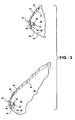
- Figure 5 is an enlarged perspective view of two parabolic-shaped portions formed as part of an optic, according to the present invention.
- Figure 6 is a greatly enlarged view of part of a parabolic-shaped portion of an optic, according to the present invention.
- a headlamp assembly incorporating an optic of the present invention used for a turn signal device is shown in the Figures generally at 10.
- the headlamp 10 includes an optic in the form of a light pipe 12 which is mounted in a housing 14. Also mounted in the housing 14 is a moving bezel 16 which is used for holding a plurality of optics (not shown). The plurality of optics is used in conjunction with light emitting diodes (LEDs, also not shown) for producing the low-beam and high-beams portions of the headlamp 10.
- LEDs light emitting diodes
- the heat sink 20 absorbs heat produced in the headlamp 10.
- the light pipe 12 also includes several parabolic-shaped portions 24. In this embodiment, there are five parabolic portions, but it is within the scope of the invention that more or less parabolic portions 24 may be used.
- the light pipe 12 also has an output surface 26, where light is directed through the output surface 26 in an area in front of the vehicle. In this embodiment, the output surface 26, as well as the rest of the width of the light pipe 12 is ten millimeters wide to produce a beam having a horizontal viewing angle of thirty degrees, but it is within the scope of the invention that other widths may be used as well to vary the horizontal viewing angle as desired.
- the parabolic portions 24 also include side surfaces 28, the side surfaces do not emit light when the light pipe 12 is activated.
- the light pipe 12 also includes a notch, generally shown at 30, formed in each of the parabolic-shaped portions 24. Formed as part of each notch 30 are a first angled input surface 32, a second angled input surface 34, and an arcuate input surface 36. Located in close proximity to the input surfaces 32,34,36 is a light source, which in this embodiment is an LED, shown generally at 38.
- the parabolic-shaped portions 24 also include a first parabolic surface, shown generally at 40, and a second parabolic surface, shown generally at 42. Each of the parabolic surfaces 40,42 include a plurality of flat surfaces 44 for directing light through the light pipe 12.
- first parabolic surface 40 for the bottom four parabolic-shaped portions 24 does not extend all the way to the output surface 26; it can also be seen that the second parabolic surface 42 for top four parabolic-shaped portions 24 does not extend all the way to the output surface 26. Only the first parabolic surface 40 for the top parabolic-shaped portion 24 and the second parabolic surface 42 for the bottom parabolic-shaped portion 24 extend to the output surface 26. The reason for this is to allow the light from each of the LEDs 38 to blend together so as to present a smooth, continuous light output of the output surface 26.
- the light pipe 12 incorporates the principles of total internal reflection (TIR) to maximize the efficiency of the light produced by the LEDs 38.
- TIR total internal reflection
- the shape of the parabolic surfaces 40,42 along with the flat surfaces 44, combined with the fact that the side surfaces 28 do not emit light, as well as the light pipe 12 operating under the principles of TIR will ensure that the maximum amount of light produced by the LED 38 will exit only at the output surface 26.
- the TIR aspects of the light pipe 12 also help to provide maximum efficiency.
- the light pipe 12 of the present invention is used for a turn signal in this embodiment. As shown in Figures 1 and 3 , the light pipe 12 is located relatively close to the moving bezel 16. Certain regulations for the production of automobiles require specific levels of illumination for a turn signal lamp to prevent the beam produced by the turn signal lamp in a forward direction from becoming diluted by the low-beam pattern produced by a headlamp. These regulations are directed towards the condition where the turn signal lamp is manufactured to be located a specific distance from the portion of the headlamp which produces the low beam. For a turn signal located at a distance away from a headlamp, the current minimum requirement for the functional lighted lens area of a single compartment lamp must be at least 37.5 cm 2 for a rear lamp and at least 22 cm 2 for a front lamp. The light pipe 12 having the configuration described will produce light output which is two-and-a-half times higher than what is normally required of a turn signal lamp, meeting these requirements for when the turn signal is located less than 60 mm away from the headlamp.
Landscapes
- Engineering & Computer Science (AREA)
- General Engineering & Computer Science (AREA)
- Mechanical Engineering (AREA)
- Physics & Mathematics (AREA)
- Microelectronics & Electronic Packaging (AREA)
- Optics & Photonics (AREA)
- Non-Portable Lighting Devices Or Systems Thereof (AREA)
Abstract
Description
- The present invention relates to optics used for turn signals in a headlamp assembly of an automobile.
- Turn signals used in headlamp assemblies for automobiles are generally known. Turn signals are often used for providing an indication to other drivers that a vehicle is going to turn either left or right. Typically, there is also more than one turn signal on the automobile, usually there is at least one turn signal for providing an indication to other drivers located to the side of the vehicle that the driver is turning, as well as other turn signals for giving an indication to drivers located at the front and rear of the vehicle that the driver is turning. There are typically turn signals at the rear of the vehicle, towards the front of the vehicle, and on the sides of the vehicle. With some modern vehicles, turn signals have also been incorporated into the side mirrors.
- There are various government regulations which provide standards which are used in the construction of headlamps and turn signals to have a minimum level of brightness, as well as a specified direction in which the light produced by the headlamps and turn signals must be directed. Some of these standards relate to the position of a turn signal in relation to a headlamp assembly. More specifically, in the case where the front turn signal is mounted in close proximity to the low beam headlamp, or in close proximity to any additional lamp used to supplement or in lieu of the low beam, such as an auxiliary low beam or fog lamp, the light produced by the turn signal must be two-and-a-half times the normal required amount of luminous intensity. The current minimum requirement for the functional lighted lens area of a single compartment lamp must be at least 37.5 cm2 for a rear lamp and at least 22 cm2 for a front lamp.
- One specific regulation applies to the condition where the spacing of the turn signal is within 60 mm of the lighted edge of the low beam headlamp of the headlamp assembly. Automotive manufacturers have had to account for these various regulations when designing the headlamp assembly and turn signals of an automobile. Some of these solutions have involved placing the turn signal at a distance away from the headlamp so as to only have the turn signal produce the minimum required luminous intensity. However, due to the various styling demands of the consumer market, it is often desired to incorporate the turn signals at a location close to the headlamp assembly, necessitating the turn signal having the ability to meet the requirements for having two-and-a-half times minimum luminous intensity.
- Accordingly, there exists a need for a turn signal assembly which can be located in close proximity to the headlamp assembly while still meeting various government regulations for luminous intensity.
- The present invention is a headlamp assembly which includes an optic used for providing a turn signal which meets the government requirements for luminous intensity when the turn signal is located near or next to the headlamp assembly. The present invention is a headlamp assembly which includes a housing, at least one optic disposed within the housing, as well as at least one light source which is operable with the optic such that light is emitted from the optic which meets or exceeds present regulatory requirements. The present invention also includes an outer lens mounted on the housing such that light emitted from the optic passes through the outer lens.
- Further areas of applicability of the present invention will become apparent from the detailed description provided hereinafter. It should be understood that the detailed description and specific examples, while indicating the preferred embodiment of the invention, are intended for purposes of illustration only and are not intended to limit the scope of the invention.
- The present invention will become more fully understood from the detailed description and the accompanying drawings, wherein:
-
Figure 1 is a side view of a headlamp assembly incorporating an optic, according to the present invention; -
Figure 2 is an exploded view of a headlamp assembly incorporating an optic, according to the present invention; -
Figure 3 is a front view of a headlamp assembly incorporating an optic, according to the present invention; -
Figure 4 is a perspective view of an optic, according to the present invention; -
Figure 5 is an enlarged perspective view of two parabolic-shaped portions formed as part of an optic, according to the present invention; and -
Figure 6 is a greatly enlarged view of part of a parabolic-shaped portion of an optic, according to the present invention. - The following description of the preferred embodiment(s) is merely exemplary in nature and is in no way intended to limit the invention, its application, or uses.
- A headlamp assembly incorporating an optic of the present invention used for a turn signal device is shown in the Figures generally at 10. The
headlamp 10 includes an optic in the form of alight pipe 12 which is mounted in ahousing 14. Also mounted in thehousing 14 is a movingbezel 16 which is used for holding a plurality of optics (not shown). The plurality of optics is used in conjunction with light emitting diodes (LEDs, also not shown) for producing the low-beam and high-beams portions of theheadlamp 10. There is also afixed bezel 18 which surrounds themoving bezel 16 and thelight pipe 12 when mounted in thehousing 14. - Also connected to the
housing 14 is aheat sink 20. Theheat sink 20 absorbs heat produced in theheadlamp 10. There is also anouter lens 22 where light is directed through and away from theheadlamp 10 to illuminate the area in front of a vehicle. - Referring to
Figures 4-6 , thelight pipe 12 also includes several parabolic-shaped portions 24. In this embodiment, there are five parabolic portions, but it is within the scope of the invention that more or lessparabolic portions 24 may be used. Thelight pipe 12 also has anoutput surface 26, where light is directed through theoutput surface 26 in an area in front of the vehicle. In this embodiment, theoutput surface 26, as well as the rest of the width of thelight pipe 12 is ten millimeters wide to produce a beam having a horizontal viewing angle of thirty degrees, but it is within the scope of the invention that other widths may be used as well to vary the horizontal viewing angle as desired. - The
parabolic portions 24 also includeside surfaces 28, the side surfaces do not emit light when thelight pipe 12 is activated. Thelight pipe 12 also includes a notch, generally shown at 30, formed in each of the parabolic-shaped portions 24. Formed as part of eachnotch 30 are a firstangled input surface 32, a secondangled input surface 34, and anarcuate input surface 36. Located in close proximity to theinput surfaces side surfaces 28, the parabolic-shaped portions 24 also include a first parabolic surface, shown generally at 40, and a second parabolic surface, shown generally at 42. Each of theparabolic surfaces flat surfaces 44 for directing light through thelight pipe 12. - It can be seen in
Figures 1-4 that the firstparabolic surface 40 for the bottom four parabolic-shaped portions 24 does not extend all the way to theoutput surface 26; it can also be seen that the secondparabolic surface 42 for top four parabolic-shaped portions 24 does not extend all the way to theoutput surface 26. Only the firstparabolic surface 40 for the top parabolic-shaped portion 24 and the secondparabolic surface 42 for the bottom parabolic-shaped portion 24 extend to theoutput surface 26. The reason for this is to allow the light from each of theLEDs 38 to blend together so as to present a smooth, continuous light output of theoutput surface 26. - The
light pipe 12 incorporates the principles of total internal reflection (TIR) to maximize the efficiency of the light produced by theLEDs 38. The shape of theparabolic surfaces flat surfaces 44, combined with the fact that theside surfaces 28 do not emit light, as well as thelight pipe 12 operating under the principles of TIR will ensure that the maximum amount of light produced by theLED 38 will exit only at theoutput surface 26. The TIR aspects of thelight pipe 12 also help to provide maximum efficiency. - The
light pipe 12 of the present invention is used for a turn signal in this embodiment. As shown inFigures 1 and 3 , thelight pipe 12 is located relatively close to the movingbezel 16. Certain regulations for the production of automobiles require specific levels of illumination for a turn signal lamp to prevent the beam produced by the turn signal lamp in a forward direction from becoming diluted by the low-beam pattern produced by a headlamp. These regulations are directed towards the condition where the turn signal lamp is manufactured to be located a specific distance from the portion of the headlamp which produces the low beam. For a turn signal located at a distance away from a headlamp, the current minimum requirement for the functional lighted lens area of a single compartment lamp must be at least 37.5 cm2 for a rear lamp and at least 22 cm2 for a front lamp. Thelight pipe 12 having the configuration described will produce light output which is two-and-a-half times higher than what is normally required of a turn signal lamp, meeting these requirements for when the turn signal is located less than 60 mm away from the headlamp. - The description of the invention is merely exemplary in nature and, thus, variations that do not depart from the gist of the invention are intended to be within the scope of the invention. Such variations are not to be regarded as a departure from the spirit and scope of the invention.
- Various aspects of the invention are recited in the following numbered list:
- 1. A headlamp assembly, comprising:
- a housing;
- at least one total internal reflection (TIR) optic disposed within said housing;
- at least one light source operable with said at least one optic such that light is emitted from said at least one optic substantially without loss of light intensity, and light emitted from said at least one optic is visible when said optic is located in proximity to a device producing a beam pattern from said headlamp assembly; and
- an outer lens mounted on said housing such that light emitted from said at least one optic passes through said outer lens.
- 2. The headlamp assembly of aspect 1, said at least one optic further comprising:
- at least one output surface; and
- a plurality of parabolic-shaped portions, wherein said at least one light source is operable for delivering light to said plurality of parabolic-shaped portions, and said plurality of parabolic-shaped portions collimate light such that light emitted from said at least one output surface is of an increased intensity, and said plurality of parabolic-shaped portions direct substantially all of the light produced by said light source out of said at least one output surface.
- 3. The headlamp assembly of aspect 2, each of said plurality of parabolic-shaped portions further comprising:
- a first parabolic surface formed as part of said at least one optic;
- a second parabolic surface formed as part of said at least one optic such that light entering at least one optic from said at least one light source is directed toward said at least one output surface by said first parabolic surface and said second parabolic surface; and
- a notch for receiving light from said at least one light source, said notch being disposed between said first parabolic surface and said second parabolic surface.
- 4. The headlamp assembly of aspect 3, further comprising a plurality of flat surfaces formed as part of each of said first parabolic surface and said second parabolic surface for directing light toward said at least one output surface.
- 5. The headlamp assembly of aspect 3 or 4, said notch further comprising:
- a first input surface located in proximity to said at least one light source;
- a second input surface located in proximity to said at least one light source; and
- an arcuate input surface located in proximity to said at least one light source, said arcuate surface terminating into said first input surface and said second input surface such that substantially all the light emitted from said at least one light source is received by said first input surface, said second input surface, and said arcuate input surface.
- 6. The headlamp assembly of any one of aspects 1 to 5, said at least one optic further comprising at least two side surfaces.
- 7. The headlamp assembly of any one of aspects 1 to 6, wherein said at least one optic emits substantially all of the light produced by said at least one light source through the use of total internal reflection (TIR).
- 8. The headlamp assembly of any one of aspects 1 to 7, said at least one light source further comprising a light emitting diode (LED).
- 9. The headlamp assembly of any one of aspects 1 to 8, wherein light emitted from said at least one optic at an increased intensity is two-and-a-half times higher than a regulatory requirement with an illuminated lens area of 22.5 cm2, when said headlamp assembly is used at the front of a vehicle.
- 10. A headlamp assembly for use in with a motor vehicle comprising:
- a housing;
- at least one total internal reflection (TIR) optic disposed within said housing;
- at least one light source, said at least one optic operable for receiving substantially all of the light produced by said at least one light source, and said at least one optic is shaped such that light emitted from said at least one optic is visible when said at least one optic is located in proximity to a device producing a beam pattern; and
- an outer lens mounted on said housing, such that light emitted from said at least one optic passes through said outer lens.
- 11. The headlamp assembly of
aspect 10, said at least one optic further comprising:- at least one output surface; and
- a plurality of parabolic-shaped portions operable for receiving light produced by said at least one light source and said plurality of parabolic-shaped portions are operable for producing light at said at least one output surface of an increased intensity.
- 12. The headlamp assembly of aspect 11, each of said plurality of parabolic surfaces further comprising:
- a first parabolic surface;
- a second parabolic surface operable with said first parabolic surface for directing substantially all of the light in said at least one optic out of said at least one output surface; and
- a notch, wherein said first parabolic surface extends to said notch, and said second parabolic surface extends to said notch.
- 13. The headlamp assembly of
aspect 12, said at least one optic further comprising:- a plurality of flat surfaces formed along said first parabolic surface and said second parabolic surface, said plurality of flat surfaces operable for directing light toward said at least one light output surface; and
- at least two side surfaces substantially perpendicular to said plurality of flat surfaces.
- 14. The headlamp assembly of
aspect 12 or 13, said notch further comprising:- a first input surface, said first parabolic surface terminating into said first input surface;
- a second input surface, said second parabolic surface terminating into said second input surface; and
- an arcuate surface, said first input surface terminating into said arcuate surface and said second input surface terminating into said arcuate surface such that substantially all of the light produced by said at least one light source is delivered to said first input surface, said second input surface, and said arcuate surface.
- 15. The headlamp assembly of any one of
aspects 10 to 14, wherein said at least one light source is a light emitting diode (LED). - 16. The headlamp assembly of any one of
aspects 10 to 15, wherein said at least one optic directs light out of said at least one optic through the use of total internal reflection (TIR). - 17. The headlamp assembly of any one of
aspects 10 to 16, wherein light emitted from said at least one optic at an increased intensity is two-and-a-half times higher than a regulatory requirement with an illuminated lens area of 22.5 cm2, when said headlamp assembly is used at the front of a vehicle. - 18. An optic used for a headlamp assembly, said optic comprising:
- at least one output surface;
- a first parabolic surface operable for directing light out of said at least one output surface;
- a second parabolic surface operable for directing light out of said at least one output surface;
- a notch, said first parabolic surface terminating in said notch, and said second parabolic surface terminating in said notch;
- a light source operable with said notch for delivering light to said optic such that substantially all of the light produced by said light source exits said optic out of said at least one output surface through the use of total internal reflection (TIR), and the light emitted from said optic is visible when said optic is located in proximity to a device in said headlamp assembly that produces a beam pattern; and
- at least two side surfaces substantially perpendicular to said first parabolic surface and said second parabolic surface.
- 19. The optic of
aspect 18, said notch further comprising:- a first input surface located in proximity to said light source;
- a second input surface, located in proximity to said light source; and
- an arcuate surface extending to both of said first input surface and said second input surface such that substantially all of the light produced by said light source is directed to said first input surface, said second input surface and said arcuate input surface.
- 20. The optic of
aspect 18 or 19, further comprising a plurality of flat surfaces formed on both of said first parabolic surface and said second parabolic surface. - 21. The optic of any one of
aspects 18 to 20, said headlamp assembly further comprising:- a housing;
- a moving bezel disposed within said housing in proximity to said optic;
- a fixed bezel surrounding said moving bezel and said optic;
- an outer lens connected to said housing such that as light passes through said at least one output surface, light will also pass through said outer lens; and
- a heatsink connected to said housing to remove heat produced by said optic.
- 22. The optic of any one of
aspects 18 to 21, said light source further comprising a light emitting diode (LED). - 23. The headlamp assembly of any one of
aspects 18 to 22, wherein light emitted from said at least one output surface of said at least one optic at an increased intensity is two-and-a-half times higher than a regulatory requirement with an illuminated lens area of 22.5 cm2, when said headlamp assembly is used at the front of a vehicle.
Claims (14)
- A headlamp assembly, comprising:a housing;at least one total internal reflection (TIR) optic disposed within the housing;at least one light source, the at least one optic operable for receiving substantially all of the light produced by the at least one light source, and the at least one optic is shaped such that light emitted from the at least one optic is visible when the at least one optic is located in proximity to a device producing a beam pattern; andan outer lens mounted on the housing, such that light emitted from the at least one optic passes through the outer lens.
- The headlamp assembly of claim 1, the at least one optic further comprising:at least one output surface; anda plurality of parabolic-shaped portions operable for receiving light produced by the at least one light source and the plurality of parabolic-shaped portions are operable for producing light at the at least one output surface of an increased intensity.
- The headlamp assembly of claim 2, wherein the plurality of parabolic-shaped portions direct substantially all of the light produced by the light source out of the at least one output surface.
- The headlamp assembly of claim 2 or 3, each of the plurality of parabolic surfaces further comprising:a first parabolic surface;a second parabolic surface operable with the first parabolic surface for directing substantially all of the light in the at least one optic out of the at least one output surface; anda notch for receiving light from the at least one light source.
- The headlamp assembly of claim 4, wherein the first parabolic surface formed as part of the at least one optic and/or the second parabolic surface formed as part of the at least one optic and/or the notch is disposed between the first parabolic surface and the second parabolic surface.
- The headlamp assembly of claim 4, wherein the first parabolic surface extends to the notch, and the second parabolic surface extends to the notch.
- The headlamp assembly of any one of claims 4 to 6, the at least one optic further comprising:a plurality of flat surfaces formed along the first parabolic surface and the second parabolic surface, the plurality of flat surfaces operable for directing light toward the at least one light output surface.
- The headlamp assembly of any one of claims 4 to 7, wherein the at least one optic further comprises at least at least two side surfaces.
- The headlamp assembly of claim 8, wherein the at least two side surfaces are substantially perpendicular to the plurality of flat surfaces.
- The headlamp assembly of any one of claims 4 to 9, the notch further comprising:a first input surface, the first parabolic surface terminating into the first input surface;a second input surface, the second parabolic surface terminating into the second input surface; andan arcuate surface, the first input surface terminating into the arcuate surface and the second input surface terminating into the arcuate surface such that substantially all of the light produced by the at least one light source is delivered to the first input surface, the second input surface, and the arcuate surface.
- An optic used for a headlamp assembly, the optic comprising:at least one output surface;a first parabolic surface operable for directing light out of the at least one output surface;a second parabolic surface operable for directing light out of the at least one output surface;a notch, the first parabolic surface terminating in the notch, and the second parabolic surface terminating in the notch;a light source operable with the notch for delivering light to the optic such that substantially all of the light produced by the light source exits the optic out of the at least one output surface through the use of total internal reflection (TIR), and the light emitted from the optic is visible when the optic is located in proximity to a device in the headlamp assembly that produces a beam pattern; andat least two side surfaces substantially perpendicular to the first parabolic surface and the second parabolic surface.
- The optic of claim 11, the notch further comprising:a first input surface located in proximity to the light source;a second input surface, located in proximity to the light source; andan arcuate surface extending to both of the first input surface and the second input surface such that substantially all of the light produced by the light source is directed to the first input surface, the second input surface and the arcuate input surface.
- The optic of claim 11 or 12, further comprising a plurality of flat surfaces formed on both of the first parabolic surface and the second parabolic surface.
- The optic of any one of claims 11 to 13, the headlamp assembly further comprising:a housing;a moving bezel disposed within the housing in proximity to the optic;a fixed bezel surrounding the moving bezel and the optic;an outer lens connected to the housing such that as light passes through the at least one output surface, light will also pass through the outer lens; anda heatsink connected to the housing to remove heat produced by the optic.
Applications Claiming Priority (1)
| Application Number | Priority Date | Filing Date | Title |
|---|---|---|---|
| US12/229,396 US8061880B2 (en) | 2008-08-22 | 2008-08-22 | High efficiency light pipe—H.E.L.P. |
Publications (3)
| Publication Number | Publication Date |
|---|---|
| EP2157363A2 true EP2157363A2 (en) | 2010-02-24 |
| EP2157363A3 EP2157363A3 (en) | 2010-08-25 |
| EP2157363B1 EP2157363B1 (en) | 2020-04-22 |
Family
ID=41217810
Family Applications (1)
| Application Number | Title | Priority Date | Filing Date |
|---|---|---|---|
| EP09010640.2A Active EP2157363B1 (en) | 2008-08-22 | 2009-08-19 | Optical element for vehicle lamp |
Country Status (3)
| Country | Link |
|---|---|
| US (1) | US8061880B2 (en) |
| EP (1) | EP2157363B1 (en) |
| CA (1) | CA2674388C (en) |
Cited By (7)
| Publication number | Priority date | Publication date | Assignee | Title |
|---|---|---|---|---|
| EP2159477A3 (en) * | 2008-08-25 | 2010-09-01 | Koito Manufacturing Co., Ltd | Vehicle lamp using a light guide |
| FR2993633A1 (en) * | 2012-07-23 | 2014-01-24 | Valeo Vision | LIGHT GUIDE FOR A DEVICE FOR LIGHTING AND / OR SIGNALING A MOTOR VEHICLE |
| CN103629623A (en) * | 2012-08-21 | 2014-03-12 | 卡车灯欧洲有限责任公司 | Optical body for a vehicle light |
| EP2607776A3 (en) * | 2011-12-22 | 2015-06-17 | Automotive Lighting Reutlingen GmbH | Lighting device for a motor vehicle with a light guide structure |
| FR3025865A1 (en) * | 2014-09-16 | 2016-03-18 | Valeo Vision | LIGHTING DEVICE OF A VEHICLE USING A MULTISOURCE OPTICAL LENS |
| CN108368984A (en) * | 2015-12-22 | 2018-08-03 | Zkw集团有限责任公司 | The headlamp at least one laser module for vehicle |
| EP3149394B1 (en) * | 2014-05-26 | 2021-11-17 | Feka Otomotiv Mamulleri Sanayi Ve Ticaret A.S. | Vehicle illumination lamp with light curtain/guide |
Families Citing this family (27)
| Publication number | Priority date | Publication date | Assignee | Title |
|---|---|---|---|---|
| US8465190B2 (en) * | 2009-05-22 | 2013-06-18 | Sylvan R. Shemitz Designs Incorporated | Total internal reflective (TIR) optic light assembly |
| JP5441801B2 (en) * | 2010-04-12 | 2014-03-12 | 株式会社小糸製作所 | Vehicle lighting |
| DE102010044424A1 (en) * | 2010-09-04 | 2012-03-08 | Hella Kgaa Hueck & Co. | Illumination device e.g. tail light for vehicle, has divergent lens elements provided in narrow side of flat light guide element resulting in formation of divergent lens surface where combined light is scattered within element |
| US8746934B2 (en) | 2010-11-12 | 2014-06-10 | Rambus Delaware Llc | Lighting assembly with asymmetrical light ray angle distribution |
| DE102011018508C5 (en) * | 2011-04-23 | 2016-06-30 | Automotive Lighting Reutlingen Gmbh | Optical fiber element arrangement and motor vehicle lighting device with such a light guide element arrangement |
| DE102011002340A1 (en) * | 2011-04-29 | 2012-10-31 | Hella Kgaa Hueck & Co. | Lighting device for vehicle, has light source sheet guiding element having secondary narrow side whose lens-shaped surface is formed as layer from several strips extending between flat sides of lens segments formed by decoupling lens |
| TW201300702A (en) * | 2011-05-13 | 2013-01-01 | Rambus Inc | Lighting assembly |
| DE102012211284A1 (en) * | 2012-06-29 | 2014-01-02 | Automotive Lighting Reutlingen Gmbh | Light-guiding element for lighting device and light guide, has light entry surface for entry of light in light-guiding element and light exit surface spaced from light entry surface, by which light guided in light-guiding element is exit |
| FR2995268B1 (en) * | 2012-09-07 | 2015-07-17 | Renault Sa | METHOD AND DEVICE FOR CONTROLLING A REAR FOG LIGHT IN A MOTOR VEHICLE |
| JP6203519B2 (en) * | 2012-09-13 | 2017-09-27 | 株式会社小糸製作所 | Vehicle lighting |
| FR2995977B1 (en) * | 2012-09-26 | 2019-06-28 | Valeo Vision | LIGHT GUIDE FOR A DEVICE FOR LIGHTING AND / OR SIGNALING A MOTOR VEHICLE |
| JP6256972B2 (en) * | 2013-08-30 | 2018-01-10 | 株式会社小糸製作所 | Vehicle lighting |
| DE102014102496B4 (en) * | 2014-02-26 | 2026-04-23 | HELLA GmbH & Co. KGaA | Lighting device for vehicles |
| JP6341771B2 (en) * | 2014-06-16 | 2018-06-13 | 株式会社小糸製作所 | Vehicle lighting |
| USD744158S1 (en) * | 2014-08-01 | 2015-11-24 | Gm Globlal Technology Operations Llc | Vehicle rear taillamp lens |
| FR3032514B1 (en) * | 2015-02-05 | 2018-08-10 | Valeo Vision | LUMINOUS MODULE OF A VEHICLE COMPATIBLE TO LEFT TRAFFIC AND RIGHT TRAFFIC |
| JP6517078B2 (en) * | 2015-04-28 | 2019-05-22 | 株式会社小糸製作所 | Vehicle lamp |
| EP3510319A1 (en) | 2016-09-12 | 2019-07-17 | Lumileds LLC | Interconnectable light guide tiles |
| US10569693B2 (en) | 2017-05-31 | 2020-02-25 | Grote Industries, Inc. | Electric lamp having a cover with a light guide |
| DE102017128841B4 (en) * | 2017-12-05 | 2020-08-20 | Dr. Ing. H.C. F. Porsche Aktiengesellschaft | Light guide body for a lighting device of a motor vehicle |
| CN108397743B (en) * | 2018-04-13 | 2025-09-16 | 华域视觉科技(上海)有限公司 | Optical module and car light |
| US11098858B2 (en) | 2018-04-26 | 2021-08-24 | Milwaukee Electric Tool Corporation | Portable light having a pivotable light head |
| USD906559S1 (en) | 2018-04-26 | 2020-12-29 | Milwaukee Electric Tool Corporation | Light |
| US10527249B2 (en) * | 2018-05-31 | 2020-01-07 | North American Lighting, Inc. | Vehicle lamp and projection lens |
| DE102018209368B4 (en) | 2018-06-12 | 2020-01-02 | Fraunhofer-Gesellschaft zur Förderung der angewandten Forschung e.V. | Optics for transmitting and / or receiving element, communication module, arrays of communication modules, system of several communication modules and method for producing an optic |
| US10895361B1 (en) | 2019-08-22 | 2021-01-19 | Valeo North America, Inc. | Optical device for an automobile vehicle |
| US10962194B1 (en) * | 2019-12-14 | 2021-03-30 | Valeo North America, Inc. | Motor vehicle light guide and reflective coupler system for outboard homogenous lit appearance of lamp module |
Family Cites Families (13)
| Publication number | Priority date | Publication date | Assignee | Title |
|---|---|---|---|---|
| DE19507234B4 (en) * | 1995-03-02 | 2005-06-16 | Fer Fahrzeugelektrik Gmbh | Vehicle signal light with several LEDs |
| DE69803297T2 (en) * | 1997-08-12 | 2002-08-22 | Breault Res Organization Inc | DOUBLE REFLECTIVE LENS |
| DE10051464B4 (en) * | 2000-10-17 | 2011-08-11 | OSRAM Opto Semiconductors GmbH, 93055 | fresnel lens |
| DE10231326A1 (en) * | 2002-07-11 | 2004-02-19 | Hella Kg Hueck & Co. | Light unit for automobile e.g. automobile headlamp, has spaced light source elements associated with light conduction elements positioned behind light disc |
| US20040264189A1 (en) * | 2003-06-30 | 2004-12-30 | Kuo-Fen Shu | LED spotlight (type II) |
| JP4328954B2 (en) * | 2003-10-22 | 2009-09-09 | 矢崎総業株式会社 | Interior lighting |
| JP4113111B2 (en) * | 2003-12-24 | 2008-07-09 | 株式会社小糸製作所 | VEHICLE LIGHT UNIT AND VEHICLE LIGHTING LIGHT |
| JP4497348B2 (en) * | 2004-01-13 | 2010-07-07 | 株式会社小糸製作所 | Vehicle lighting |
| JP4339143B2 (en) * | 2004-02-10 | 2009-10-07 | 株式会社小糸製作所 | Vehicle lamp unit |
| ATE453930T1 (en) * | 2004-10-14 | 2010-01-15 | Fiat Ricerche | OPTICAL ELEMENT AND MODULE FOR PROJECTING A BUNDLE OF LIGHTS, AND MOTOR VEHICLE LAMP HAVING A PLURALITY OF SUCH MODULES |
| AT502490B1 (en) * | 2006-04-27 | 2007-04-15 | Zizala Lichtsysteme Gmbh | light guide |
| US7806572B2 (en) * | 2007-03-29 | 2010-10-05 | Magna International Inc. | Headlamp assembly with isolated optics chamber |
| US20080304277A1 (en) * | 2007-06-07 | 2008-12-11 | Jeyachandrabose Chinniah | Increased efficiency led projector optic assembly |
-
2008
- 2008-08-22 US US12/229,396 patent/US8061880B2/en active Active
-
2009
- 2009-07-30 CA CA2674388A patent/CA2674388C/en active Active
- 2009-08-19 EP EP09010640.2A patent/EP2157363B1/en active Active
Cited By (12)
| Publication number | Priority date | Publication date | Assignee | Title |
|---|---|---|---|---|
| EP2159477A3 (en) * | 2008-08-25 | 2010-09-01 | Koito Manufacturing Co., Ltd | Vehicle lamp using a light guide |
| EP2607776A3 (en) * | 2011-12-22 | 2015-06-17 | Automotive Lighting Reutlingen GmbH | Lighting device for a motor vehicle with a light guide structure |
| FR2993633A1 (en) * | 2012-07-23 | 2014-01-24 | Valeo Vision | LIGHT GUIDE FOR A DEVICE FOR LIGHTING AND / OR SIGNALING A MOTOR VEHICLE |
| EP2690349A1 (en) * | 2012-07-23 | 2014-01-29 | Valeo Vision | Light guide for a lighting and/or signalling device of a motor vehicle |
| US9574731B2 (en) | 2012-07-23 | 2017-02-21 | Valeo Vision | Light guide for an automobile lighting and/or signaling device |
| CN103629623A (en) * | 2012-08-21 | 2014-03-12 | 卡车灯欧洲有限责任公司 | Optical body for a vehicle light |
| EP3149394B1 (en) * | 2014-05-26 | 2021-11-17 | Feka Otomotiv Mamulleri Sanayi Ve Ticaret A.S. | Vehicle illumination lamp with light curtain/guide |
| FR3025865A1 (en) * | 2014-09-16 | 2016-03-18 | Valeo Vision | LIGHTING DEVICE OF A VEHICLE USING A MULTISOURCE OPTICAL LENS |
| EP2998645A3 (en) * | 2014-09-16 | 2016-06-15 | Valeo Vision | Lighting device of a vehicle using a multi-source optical lens |
| US9879838B2 (en) | 2014-09-16 | 2018-01-30 | Valeo Vision | Vehicle lighting device using a multiple-source optical lens |
| CN108368984A (en) * | 2015-12-22 | 2018-08-03 | Zkw集团有限责任公司 | The headlamp at least one laser module for vehicle |
| CN108368984B (en) * | 2015-12-22 | 2020-11-03 | Zkw集团有限责任公司 | Headlamps with at least one laser module for vehicles |
Also Published As
| Publication number | Publication date |
|---|---|
| CA2674388A1 (en) | 2010-02-22 |
| US20100046242A1 (en) | 2010-02-25 |
| US8061880B2 (en) | 2011-11-22 |
| EP2157363B1 (en) | 2020-04-22 |
| EP2157363A3 (en) | 2010-08-25 |
| CA2674388C (en) | 2017-10-31 |
Similar Documents
| Publication | Publication Date | Title |
|---|---|---|
| US8061880B2 (en) | High efficiency light pipe—H.E.L.P. | |
| US9771016B2 (en) | Vehicle light apparatus | |
| EP2071228B1 (en) | Vehicle lamp assembly | |
| EP2187115B1 (en) | Vehicular lamp | |
| EP3988840B1 (en) | Vehicle lamp | |
| US9447941B2 (en) | Lamp for vehicle | |
| EP3553370B1 (en) | Vehicle lamp | |
| US10661699B2 (en) | Lighting tool for vehicle including light sources and light guide body | |
| US20060285348A1 (en) | Vehicular light assembly | |
| JP7490514B2 (en) | Vehicle lighting fixtures | |
| US10612743B2 (en) | Vehicle lamp | |
| EP3572723B1 (en) | Lighting tool for vehicle | |
| JP2022003614A (en) | Vehicular lamp fitting | |
| CN107435882B (en) | lighting device | |
| JP6470020B2 (en) | Lighting device | |
| US11873960B2 (en) | Vehicular lamp | |
| JP2021153002A (en) | Vehicle lamp | |
| JP2018098079A (en) | Vehicular headlight | |
| KR101987295B1 (en) | Lamp for vehicle | |
| CN121039432A (en) | Vehicle lights | |
| WO2019069682A1 (en) | Vehicle headlamp | |
| EP3620329B1 (en) | Vehicle lamp assembly | |
| JP2021174724A (en) | Vehicular lighting fixture | |
| JP2022179087A (en) | Vehicular lighting tool | |
| JP2023057694A (en) | vehicle lamp |
Legal Events
| Date | Code | Title | Description |
|---|---|---|---|
| PUAI | Public reference made under article 153(3) epc to a published international application that has entered the european phase |
Free format text: ORIGINAL CODE: 0009012 |
|
| AK | Designated contracting states |
Kind code of ref document: A2 Designated state(s): AT BE BG CH CY CZ DE DK EE ES FI FR GB GR HR HU IE IS IT LI LT LU LV MC MK MT NL NO PL PT RO SE SI SK SM TR |
|
| AX | Request for extension of the european patent |
Extension state: AL BA RS |
|
| PUAL | Search report despatched |
Free format text: ORIGINAL CODE: 0009013 |
|
| AK | Designated contracting states |
Kind code of ref document: A3 Designated state(s): AT BE BG CH CY CZ DE DK EE ES FI FR GB GR HR HU IE IS IT LI LT LU LV MC MK MT NL NO PL PT RO SE SI SK SM TR |
|
| AX | Request for extension of the european patent |
Extension state: AL BA RS |
|
| 17P | Request for examination filed |
Effective date: 20110224 |
|
| 17Q | First examination report despatched |
Effective date: 20150119 |
|
| STAA | Information on the status of an ep patent application or granted ep patent |
Free format text: STATUS: EXAMINATION IS IN PROGRESS |
|
| REG | Reference to a national code |
Ref country code: DE Ref legal event code: R079 Ref document number: 602009061773 Country of ref document: DE Free format text: PREVIOUS MAIN CLASS: F21V0005000000 Ipc: B60Q0001000000 |
|
| GRAP | Despatch of communication of intention to grant a patent |
Free format text: ORIGINAL CODE: EPIDOSNIGR1 |
|
| STAA | Information on the status of an ep patent application or granted ep patent |
Free format text: STATUS: GRANT OF PATENT IS INTENDED |
|
| RIC1 | Information provided on ipc code assigned before grant |
Ipc: B60Q 1/00 20060101AFI20191118BHEP Ipc: F21S 43/239 20180101ALI20191118BHEP Ipc: F21S 43/14 20180101ALI20191118BHEP Ipc: F21S 41/141 20180101ALI20191118BHEP Ipc: F21S 43/20 20180101ALI20191118BHEP Ipc: F21S 41/143 20180101ALI20191118BHEP Ipc: F21S 43/243 20180101ALI20191118BHEP Ipc: F21S 41/24 20180101ALI20191118BHEP Ipc: F21S 43/249 20180101ALI20191118BHEP |
|
| INTG | Intention to grant announced |
Effective date: 20191216 |
|
| GRAS | Grant fee paid |
Free format text: ORIGINAL CODE: EPIDOSNIGR3 |
|
| GRAA | (expected) grant |
Free format text: ORIGINAL CODE: 0009210 |
|
| STAA | Information on the status of an ep patent application or granted ep patent |
Free format text: STATUS: THE PATENT HAS BEEN GRANTED |
|
| AK | Designated contracting states |
Kind code of ref document: B1 Designated state(s): AT BE BG CH CY CZ DE DK EE ES FI FR GB GR HR HU IE IS IT LI LT LU LV MC MK MT NL NO PL PT RO SE SI SK SM TR |
|
| REG | Reference to a national code |
Ref country code: GB Ref legal event code: FG4D |
|
| REG | Reference to a national code |
Ref country code: CH Ref legal event code: EP |
|
| REG | Reference to a national code |
Ref country code: DE Ref legal event code: R096 Ref document number: 602009061773 Country of ref document: DE |
|
| REG | Reference to a national code |
Ref country code: IE Ref legal event code: FG4D |
|
| REG | Reference to a national code |
Ref country code: AT Ref legal event code: REF Ref document number: 1259664 Country of ref document: AT Kind code of ref document: T Effective date: 20200515 |
|
| REG | Reference to a national code |
Ref country code: LT Ref legal event code: MG4D |
|
| REG | Reference to a national code |
Ref country code: NL Ref legal event code: MP Effective date: 20200422 |
|
| PG25 | Lapsed in a contracting state [announced via postgrant information from national office to epo] |
Ref country code: SE Free format text: LAPSE BECAUSE OF FAILURE TO SUBMIT A TRANSLATION OF THE DESCRIPTION OR TO PAY THE FEE WITHIN THE PRESCRIBED TIME-LIMIT Effective date: 20200422 Ref country code: IS Free format text: LAPSE BECAUSE OF FAILURE TO SUBMIT A TRANSLATION OF THE DESCRIPTION OR TO PAY THE FEE WITHIN THE PRESCRIBED TIME-LIMIT Effective date: 20200822 Ref country code: NL Free format text: LAPSE BECAUSE OF FAILURE TO SUBMIT A TRANSLATION OF THE DESCRIPTION OR TO PAY THE FEE WITHIN THE PRESCRIBED TIME-LIMIT Effective date: 20200422 Ref country code: FI Free format text: LAPSE BECAUSE OF FAILURE TO SUBMIT A TRANSLATION OF THE DESCRIPTION OR TO PAY THE FEE WITHIN THE PRESCRIBED TIME-LIMIT Effective date: 20200422 Ref country code: PT Free format text: LAPSE BECAUSE OF FAILURE TO SUBMIT A TRANSLATION OF THE DESCRIPTION OR TO PAY THE FEE WITHIN THE PRESCRIBED TIME-LIMIT Effective date: 20200824 Ref country code: LT Free format text: LAPSE BECAUSE OF FAILURE TO SUBMIT A TRANSLATION OF THE DESCRIPTION OR TO PAY THE FEE WITHIN THE PRESCRIBED TIME-LIMIT Effective date: 20200422 Ref country code: NO Free format text: LAPSE BECAUSE OF FAILURE TO SUBMIT A TRANSLATION OF THE DESCRIPTION OR TO PAY THE FEE WITHIN THE PRESCRIBED TIME-LIMIT Effective date: 20200722 Ref country code: GR Free format text: LAPSE BECAUSE OF FAILURE TO SUBMIT A TRANSLATION OF THE DESCRIPTION OR TO PAY THE FEE WITHIN THE PRESCRIBED TIME-LIMIT Effective date: 20200723 |
|
| REG | Reference to a national code |
Ref country code: AT Ref legal event code: MK05 Ref document number: 1259664 Country of ref document: AT Kind code of ref document: T Effective date: 20200422 |
|
| PG25 | Lapsed in a contracting state [announced via postgrant information from national office to epo] |
Ref country code: HR Free format text: LAPSE BECAUSE OF FAILURE TO SUBMIT A TRANSLATION OF THE DESCRIPTION OR TO PAY THE FEE WITHIN THE PRESCRIBED TIME-LIMIT Effective date: 20200422 Ref country code: LV Free format text: LAPSE BECAUSE OF FAILURE TO SUBMIT A TRANSLATION OF THE DESCRIPTION OR TO PAY THE FEE WITHIN THE PRESCRIBED TIME-LIMIT Effective date: 20200422 Ref country code: BG Free format text: LAPSE BECAUSE OF FAILURE TO SUBMIT A TRANSLATION OF THE DESCRIPTION OR TO PAY THE FEE WITHIN THE PRESCRIBED TIME-LIMIT Effective date: 20200722 |
|
| REG | Reference to a national code |
Ref country code: DE Ref legal event code: R097 Ref document number: 602009061773 Country of ref document: DE |
|
| PG25 | Lapsed in a contracting state [announced via postgrant information from national office to epo] |
Ref country code: SM Free format text: LAPSE BECAUSE OF FAILURE TO SUBMIT A TRANSLATION OF THE DESCRIPTION OR TO PAY THE FEE WITHIN THE PRESCRIBED TIME-LIMIT Effective date: 20200422 Ref country code: EE Free format text: LAPSE BECAUSE OF FAILURE TO SUBMIT A TRANSLATION OF THE DESCRIPTION OR TO PAY THE FEE WITHIN THE PRESCRIBED TIME-LIMIT Effective date: 20200422 Ref country code: RO Free format text: LAPSE BECAUSE OF FAILURE TO SUBMIT A TRANSLATION OF THE DESCRIPTION OR TO PAY THE FEE WITHIN THE PRESCRIBED TIME-LIMIT Effective date: 20200422 Ref country code: IT Free format text: LAPSE BECAUSE OF FAILURE TO SUBMIT A TRANSLATION OF THE DESCRIPTION OR TO PAY THE FEE WITHIN THE PRESCRIBED TIME-LIMIT Effective date: 20200422 Ref country code: AT Free format text: LAPSE BECAUSE OF FAILURE TO SUBMIT A TRANSLATION OF THE DESCRIPTION OR TO PAY THE FEE WITHIN THE PRESCRIBED TIME-LIMIT Effective date: 20200422 Ref country code: DK Free format text: LAPSE BECAUSE OF FAILURE TO SUBMIT A TRANSLATION OF THE DESCRIPTION OR TO PAY THE FEE WITHIN THE PRESCRIBED TIME-LIMIT Effective date: 20200422 Ref country code: CZ Free format text: LAPSE BECAUSE OF FAILURE TO SUBMIT A TRANSLATION OF THE DESCRIPTION OR TO PAY THE FEE WITHIN THE PRESCRIBED TIME-LIMIT Effective date: 20200422 Ref country code: ES Free format text: LAPSE BECAUSE OF FAILURE TO SUBMIT A TRANSLATION OF THE DESCRIPTION OR TO PAY THE FEE WITHIN THE PRESCRIBED TIME-LIMIT Effective date: 20200422 |
|
| PG25 | Lapsed in a contracting state [announced via postgrant information from national office to epo] |
Ref country code: PL Free format text: LAPSE BECAUSE OF FAILURE TO SUBMIT A TRANSLATION OF THE DESCRIPTION OR TO PAY THE FEE WITHIN THE PRESCRIBED TIME-LIMIT Effective date: 20200422 Ref country code: SK Free format text: LAPSE BECAUSE OF FAILURE TO SUBMIT A TRANSLATION OF THE DESCRIPTION OR TO PAY THE FEE WITHIN THE PRESCRIBED TIME-LIMIT Effective date: 20200422 |
|
| PLBE | No opposition filed within time limit |
Free format text: ORIGINAL CODE: 0009261 |
|
| STAA | Information on the status of an ep patent application or granted ep patent |
Free format text: STATUS: NO OPPOSITION FILED WITHIN TIME LIMIT |
|
| 26N | No opposition filed |
Effective date: 20210125 |
|
| PG25 | Lapsed in a contracting state [announced via postgrant information from national office to epo] |
Ref country code: MC Free format text: LAPSE BECAUSE OF FAILURE TO SUBMIT A TRANSLATION OF THE DESCRIPTION OR TO PAY THE FEE WITHIN THE PRESCRIBED TIME-LIMIT Effective date: 20200422 |
|
| REG | Reference to a national code |
Ref country code: CH Ref legal event code: PL |
|
| GBPC | Gb: european patent ceased through non-payment of renewal fee |
Effective date: 20200819 |
|
| PG25 | Lapsed in a contracting state [announced via postgrant information from national office to epo] |
Ref country code: LU Free format text: LAPSE BECAUSE OF NON-PAYMENT OF DUE FEES Effective date: 20200819 Ref country code: LI Free format text: LAPSE BECAUSE OF NON-PAYMENT OF DUE FEES Effective date: 20200831 Ref country code: CH Free format text: LAPSE BECAUSE OF NON-PAYMENT OF DUE FEES Effective date: 20200831 |
|
| REG | Reference to a national code |
Ref country code: BE Ref legal event code: MM Effective date: 20200831 |
|
| PG25 | Lapsed in a contracting state [announced via postgrant information from national office to epo] |
Ref country code: SI Free format text: LAPSE BECAUSE OF FAILURE TO SUBMIT A TRANSLATION OF THE DESCRIPTION OR TO PAY THE FEE WITHIN THE PRESCRIBED TIME-LIMIT Effective date: 20200422 |
|
| PG25 | Lapsed in a contracting state [announced via postgrant information from national office to epo] |
Ref country code: FR Free format text: LAPSE BECAUSE OF NON-PAYMENT OF DUE FEES Effective date: 20200831 |
|
| PG25 | Lapsed in a contracting state [announced via postgrant information from national office to epo] |
Ref country code: IE Free format text: LAPSE BECAUSE OF NON-PAYMENT OF DUE FEES Effective date: 20200819 Ref country code: GB Free format text: LAPSE BECAUSE OF NON-PAYMENT OF DUE FEES Effective date: 20200819 Ref country code: BE Free format text: LAPSE BECAUSE OF NON-PAYMENT OF DUE FEES Effective date: 20200831 |
|
| PG25 | Lapsed in a contracting state [announced via postgrant information from national office to epo] |
Ref country code: TR Free format text: LAPSE BECAUSE OF FAILURE TO SUBMIT A TRANSLATION OF THE DESCRIPTION OR TO PAY THE FEE WITHIN THE PRESCRIBED TIME-LIMIT Effective date: 20200422 Ref country code: MT Free format text: LAPSE BECAUSE OF FAILURE TO SUBMIT A TRANSLATION OF THE DESCRIPTION OR TO PAY THE FEE WITHIN THE PRESCRIBED TIME-LIMIT Effective date: 20200422 Ref country code: CY Free format text: LAPSE BECAUSE OF FAILURE TO SUBMIT A TRANSLATION OF THE DESCRIPTION OR TO PAY THE FEE WITHIN THE PRESCRIBED TIME-LIMIT Effective date: 20200422 |
|
| PG25 | Lapsed in a contracting state [announced via postgrant information from national office to epo] |
Ref country code: MK Free format text: LAPSE BECAUSE OF FAILURE TO SUBMIT A TRANSLATION OF THE DESCRIPTION OR TO PAY THE FEE WITHIN THE PRESCRIBED TIME-LIMIT Effective date: 20200422 |
|
| P01 | Opt-out of the competence of the unified patent court (upc) registered |
Effective date: 20230517 |
|
| REG | Reference to a national code |
Ref country code: DE Ref legal event code: R082 Ref document number: 602009061773 Country of ref document: DE Representative=s name: WITTE, WELLER & PARTNER PATENTANWAELTE MBB, DE |
|
| PGFP | Annual fee paid to national office [announced via postgrant information from national office to epo] |
Ref country code: DE Payment date: 20250624 Year of fee payment: 17 |