EP2157305A2 - Gas turbine engine with variable area fan nozzle - Google Patents
Gas turbine engine with variable area fan nozzle Download PDFInfo
- Publication number
- EP2157305A2 EP2157305A2 EP09251654A EP09251654A EP2157305A2 EP 2157305 A2 EP2157305 A2 EP 2157305A2 EP 09251654 A EP09251654 A EP 09251654A EP 09251654 A EP09251654 A EP 09251654A EP 2157305 A2 EP2157305 A2 EP 2157305A2
- Authority
- EP
- European Patent Office
- Prior art keywords
- flow duct
- nozzle
- recited
- nozzle section
- section
- Prior art date
- Legal status (The legal status is an assumption and is not a legal conclusion. Google has not performed a legal analysis and makes no representation as to the accuracy of the status listed.)
- Granted
Links
Images


Classifications
-
- F—MECHANICAL ENGINEERING; LIGHTING; HEATING; WEAPONS; BLASTING
- F02—COMBUSTION ENGINES; HOT-GAS OR COMBUSTION-PRODUCT ENGINE PLANTS
- F02K—JET-PROPULSION PLANTS
- F02K3/00—Plants including a gas turbine driving a compressor or a ducted fan
- F02K3/02—Plants including a gas turbine driving a compressor or a ducted fan in which part of the working fluid by-passes the turbine and combustion chamber
- F02K3/04—Plants including a gas turbine driving a compressor or a ducted fan in which part of the working fluid by-passes the turbine and combustion chamber the plant including ducted fans, i.e. fans with high volume, low pressure outputs, for augmenting the jet thrust, e.g. of double-flow type
- F02K3/077—Plants including a gas turbine driving a compressor or a ducted fan in which part of the working fluid by-passes the turbine and combustion chamber the plant including ducted fans, i.e. fans with high volume, low pressure outputs, for augmenting the jet thrust, e.g. of double-flow type the plant being of the multiple flow type, i.e. having three or more flows
-
- F—MECHANICAL ENGINEERING; LIGHTING; HEATING; WEAPONS; BLASTING
- F02—COMBUSTION ENGINES; HOT-GAS OR COMBUSTION-PRODUCT ENGINE PLANTS
- F02K—JET-PROPULSION PLANTS
- F02K1/00—Plants characterised by the form or arrangement of the jet pipe or nozzle; Jet pipes or nozzles peculiar thereto
- F02K1/40—Nozzles having means for dividing the jet into a plurality of partial jets or having an elongated cross-section outlet
- F02K1/42—Nozzles having means for dividing the jet into a plurality of partial jets or having an elongated cross-section outlet the means being movable into an inoperative position
-
- F—MECHANICAL ENGINEERING; LIGHTING; HEATING; WEAPONS; BLASTING
- F02—COMBUSTION ENGINES; HOT-GAS OR COMBUSTION-PRODUCT ENGINE PLANTS
- F02K—JET-PROPULSION PLANTS
- F02K1/00—Plants characterised by the form or arrangement of the jet pipe or nozzle; Jet pipes or nozzles peculiar thereto
- F02K1/46—Nozzles having means for adding air to the jet or for augmenting the mixing region between the jet and the ambient air, e.g. for silencing
-
- F—MECHANICAL ENGINEERING; LIGHTING; HEATING; WEAPONS; BLASTING
- F02—COMBUSTION ENGINES; HOT-GAS OR COMBUSTION-PRODUCT ENGINE PLANTS
- F02K—JET-PROPULSION PLANTS
- F02K1/00—Plants characterised by the form or arrangement of the jet pipe or nozzle; Jet pipes or nozzles peculiar thereto
- F02K1/78—Other construction of jet pipes
- F02K1/82—Jet pipe walls, e.g. liners
- F02K1/822—Heat insulating structures or liners, cooling arrangements, e.g. post combustion liners; Infrared radiation suppressors
- F02K1/825—Infrared radiation suppressors
-
- F—MECHANICAL ENGINEERING; LIGHTING; HEATING; WEAPONS; BLASTING
- F02—COMBUSTION ENGINES; HOT-GAS OR COMBUSTION-PRODUCT ENGINE PLANTS
- F02K—JET-PROPULSION PLANTS
- F02K3/00—Plants including a gas turbine driving a compressor or a ducted fan
- F02K3/02—Plants including a gas turbine driving a compressor or a ducted fan in which part of the working fluid by-passes the turbine and combustion chamber
- F02K3/04—Plants including a gas turbine driving a compressor or a ducted fan in which part of the working fluid by-passes the turbine and combustion chamber the plant including ducted fans, i.e. fans with high volume, low pressure outputs, for augmenting the jet thrust, e.g. of double-flow type
- F02K3/075—Plants including a gas turbine driving a compressor or a ducted fan in which part of the working fluid by-passes the turbine and combustion chamber the plant including ducted fans, i.e. fans with high volume, low pressure outputs, for augmenting the jet thrust, e.g. of double-flow type controlling flow ratio between flows
Definitions
- the present invention relates to a gas turbine engine and more particularly to a nozzle system therefor.
- Variable cycle engines power aircraft over a range of operating conditions yet achieve countervailing objectives such as high specific thrust and low fuel consumption.
- a variable cycle engine essentially alters the engine bypass ratio during flight to facilitate efficient performance over a broad range of altitude and flight velocity such as to generate high thrust for maneuver and optimized fuel efficiency for loiter.
- a nozzle section of a gas turbine engine includes a regulator system in fluid communication with a secondary flow duct and a tertiary flow duct to selectively regulate communication of secondary airflow into the tertiary flow duct.
- a gas turbine engine includes a primary flow duct to communicate a primary airflow therethrough, a secondary flow duct to communicate a secondary airflow therethrough, the secondary flow duct defined at least partially around said primary flow duct, a regulator system in fluid communication with the secondary flow duct and a tertiary flow duct to selectively regulate communication of the secondary airflow into the tertiary flow duct.
- a gas turbine engine includes a primary flow duct that communicates a primary airflow from the core engine therethrough, the primary flow duct transitioning into a generally planar primary nozzle.
- a secondary flow duct communicates a secondary airflow therethrough, the secondary flow duct defined at least partially around the primary flow path to transition into a generally planar secondary nozzle downstream of the primary nozzle.
- a regulator system is in fluid communication with the secondary flow duct and a tertiary flow duct to selectively regulate communication of the secondary airflow into the tertiary flow duct.
- Figure 1A illustrates a general partial fragmentary schematic view of a gas turbofan engine 10 suspended from an engine pylon P within an engine nacelle assembly N as is typical of an aircraft designed for subsonic operation.
- the turbofan engine 10 includes a core engine within a core nacelle 12 that houses a low spool 14 and high spool 24.
- the low spool 14 includes a low pressure compressor 16 and low pressure turbine 18.
- the low spool 14 also drives a fan section 20 through a gear train 22.
- the high spool 24 includes a high pressure compressor 26 and high pressure turbine 28.
- a combustor 30 is arranged between the high pressure compressor 26 and high pressure turbine 28.
- the low and high spools 14, 24 rotate about an engine axis of rotation A.
- the engine 10 in one non-limiting embodiment is a high-bypass geared architecture aircraft engine with a bypass ratio greater than ten (10:1), a turbofan diameter significantly larger than that of the low pressure compressor 16, and the low pressure turbine 18 with a pressure ratio greater than 5:1.
- the gear train 22 may be an epicycle gear train such as a planetary gear system or other gear system with a gear reduction ratio of greater than 2.5:1. It should be understood, however, that the above parameters are only exemplary of one non-limiting embodiment of a geared architecture engine and that this disclosure is applicable to other gas turbine engines including direct drive turbofans.
- the fan section 20 communicates airflow into the core nacelle 12 to power the low pressure compressor 16 and the high pressure compressor 26.
- Core airflow compressed by the low pressure compressor 16 and the high pressure compressor 26 is mixed with the fuel in the combustor 30 and expanded over the high pressure turbine 28 and low pressure turbine 18.
- the turbines 28, 18 are coupled for rotation with, respective, spools 24, 14 to rotationally drive the compressors 26, 16 and through the gear train 22, the fan section 20 in response to the expansion.
- a primary combustion core gas exhaust flow E exits the core nacelle 12 through a core nozzle 43 defined between the core nacelle 12 and a tail cone 32.
- the core nacelle 12 is supported within the fan nacelle 34 by circumferentially space structures 36 often generically referred to as Fan Exit Guide Vanes (FEGVs).
- FEGVs Fan Exit Guide Vanes
- a secondary airflow or bypass flow path 40 is defined between the core nacelle 12 and the fan nacelle 34.
- the engine 10 generates a high bypass flow arrangement with a bypass ratio in which approximately eighty percent of the airflow which enters the fan nacelle 34 becomes bypass flow B.
- the bypass flow B communicates through the generally annular bypass flow path 40 and is discharged from the engine 10 through a variable area fan nozzle (VAFN) 42 which defines a primary bypass nozzle exit area 44A between the fan nacelle 34 and the core nacelle 12 at a fan nacelle end segment 34S of the fan nacelle 34 downstream of the fan section 20.
- VAFN variable area fan nozzle
- a secondary bypass nozzle exit area 44B is defined by the fan nacelle end segment 34S.
- Thrust is a function of density, velocity, and area. One or more of these parameters can be manipulated to vary the amount and direction of thrust provided by the bypass flow B.
- the VAFN 42 operates to effectively vary the area of the fan primary bypass nozzle exit area 44A to selectively adjust the pressure ratio of the bypass flow B in response to a controller C.
- Low pressure ratio turbofans are desirable for their high propulsive efficiency. However, low pressure ratio fans may be inherently susceptible to fan stability/flutter problems at low power and low flight speeds.
- the VAFN allows the engine to change to a more favorable fan operating line at low power, avoiding the instability region, and still provide the relatively smaller nozzle area necessary to obtain a high-efficiency fan operating line at cruise.
- the fan section 20 of the engine 10 is preferably designed for a particular flight condition -- typically cruise at 0.8M and 35,000 feet (10668 M).
- the VAFN 42 is operated to effectively vary the fan primary bypass nozzle exit area 44A to adjust fan bypass air flow such that the angle of attack or incidence on the fan blades is maintained close to the design incidence for efficient engine operation at other flight conditions, such as landing and takeoff to thus provide optimized engine operation over a range of flight conditions with respect to performance and other operational parameters such as noise levels.
- the VAFN 42 generally includes a regulator system 50 ( Figure 1 B) having a first section 52 and a second section 54 movably mounted relative the first section 52.
- the second section 54 slides about the engine axis A relative the first section 52 to change the effective area of the secondary bypass nozzle exit area 44B.
- the second section 54 in one non-limiting embodiment, slides in response to an actuator 58 (illustrated schematically) to communicate at least a portion of the bypass flow B' into the fan nacelle 34 and through the secondary bypass nozzle exit area 44B.
- the VAFN 42 changes the physical area and geometry of the bypass flow path 40 during particular flight conditions.
- the bypass flow B is effectively altered by movement of the second section 54 relative the first section 52 between a closed position ( Figure 1C ) and an open position ( Figure 1D ) with a multitude of positions therebetween ( Figure 1E ). It should be understood that an essentially infinite change in the bypass flow exit area may be provided by the regulator system 50.
- the VAFN 42 is opened by moving the second section 54 relative the first section 52 to open a tertiary flow path 60 in fluid communication with the fan nacelle end segment 34S to increase the bypass flow exit area. That is, the bypass flow exit area with the tertiary flow path 60 in an open position ( Figure 1D ) is greater than bypass flow exit area with the tertiary flow path 60 in a closed position ( Figure 1C ).
- the tertiary flow path 60 is incorporated within the fan nacelle 34 aft of the Fan Exit Guide Vanes 36 (FEGVs).
- the tertiary flow path 60 communicates bypass airflow from a fan nacelle inner wall 341 to the fan nacelle end segment 34S defined between the fan nacelle inner wall 341 and the fan nacelle outer wall 34E.
- the regulator system 50 communicates with the controller C to move the second section 54 relative the first section 52 to selectively communicate bypass airflow into the tertiary flow path 60.
- Various control systems including an engine controller or an aircraft flight control system may alternatively or additionally be utilized.
- the additional bypass flow which is exhausted from the fan nacelle end segment 34S may at least partially fill the trailing edge wake to increase overall engine thrust.
- another non-limiting embodiment includes an ejection region 70 defined through fan nacelle outer wall 34E ( Figure 2B ). That is, the tertiary flow path 60 communicates bypass airflow from a fan nacelle inner wall 34I to the ejection region 70 defined in the fan nacelle outer wall 34A.
- the ejection region 70 may include a perforated outer face sheet 74 supported by a structure 72 of the fan nacelle 34 ( Figure 2C ). It should be understood that the ejection region 70 is illustrated in partial schematic cross-section and that various arrangements may be provided to support the perforated outer face sheet 74.
- the regulator system 50 communicates with the controller C to move the second section 54 relative the first section 52 to selectively communicate bypass airflow into the tertiary flow path 60.
- the bypass airflow flows into the fan nacelle 34 through the regulator system 50 and exit through the ejection region 70 to vary the bypass flow exit area such that the bypass flow exit area with the tertiary flow path 60 in an open position is greater than exit area with the tertiary flow path 60 in a closed position. It should be understood that an essentially infinite change in the bypass flow exit area may be provided by the regulator system 50.
- a gas turbine engine 80 of a relatively low bypass configuration generally includes at least a fan section 82, a low pressure compressor section 84, a high pressure compressor section 86, a combustor section 88, a turbine section 90, an augmentor section 92, and a nozzle section 94.
- the low pressure compressor section 84, high pressure compressor section 86, combustor section 88, and turbine section 90 are generally referred to as the core engine.
- An axis of the engine A extends longitudinally through these sections. It should be understood that the engine 80 may include alternative and additional sections.
- An engine duct structure 96 and an inner structure 98 define an at least partially annular secondary flow path 100 at least partially around a perimeter of a primary flow path 102 which directs a primary combustion core gas exhaust flow (illustrated schematically by arrow E). It should be understood that the engine duct structure 96 may also at least partially define various airflow paths other than the disclosed secondary flow path 100.
- the secondary flow path 100 guides a secondary airflow S between the engine duct structure 96 and the inner structure 98.
- the secondary airflow S is typically sourced from the fan section and/or compressor section to provide a bypass flow.
- the secondary airflow S is utilized for a multiple of purposes including, for example, cooling, pressurization, and mixing with the core gas exhaust flow E prior to discharge through the nozzle section 94 during particular operational profiles.
- the secondary airflow S as defined herein is any airflow different from the primary combustion core gas exhaust flow E which may be provided as variable cycle third stream fan flow deployed, for example, by operating a set of outboard fan blades 12B located in the secondary flow path 100 which surrounds the core engine.
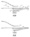
- the nozzle section 94 generally includes a secondary flow duct 104 with a generally planar secondary nozzle 106 and a primary duct 108 with a generally planar primary nozzle 110 ( Figure 3B ).
- the secondary flow duct 104 communicates secondary airflow S therethrough and the primary duct 108 communicates primary combustion core gas exhaust flow E therethrough.
- the secondary flow duct 104 in one non-limiting embodiment is a bifurcated duct arrangement having a first duct 104A and a second duct 104B (not shown) which join at the secondary nozzle 106 ( Figure 3C ).
- the primary duct 108 is generally circular in cross-section at an upstream segment and transitions into the planar primary nozzle 110 at an aft end segment ( Figure 3B ).
- the secondary nozzle 106 and the primary nozzle 110 in the disclosed non-limiting embodiment include a chevron-shaped trailing edge, however, it should be understood that any other configuration may alternatively be utilized.
- a regulator system 112 is located within the secondary flow duct 104 to selectively communicate secondary airflow S downstream of the primary nozzle 110.
- the secondary flow duct 104 includes a secondary bypass flow duct 114 which communicates with an ejection region 116 downstream of the secondary nozzle 106 through an aft deck structure 118.
- the ejection region 116 may include a perforated outer face sheet 120 of the aft deck structure 118 to control the mixture or injection of secondary airflow S to cool the aft deck structure 118. It should be understood that the ejection region 116 is illustrated in partial schematic cross-section and that various arrangements may be provided.
- the ejection region 116 may alternatively or additionally include a mesh, grid, metering hole, honeycomb or other shaping structure to directs and smooth the airflow therethrough as well as reduces noise generation.
- the regulator system 112 controls secondary airflow S into the bypass flow duct 114.
- the secondary nozzle 106 is sized for minimum secondary airflow S requirements when the regulator system 38 is in a closed position.
- the total nozzle area of the secondary nozzle 106 and the ejection region 120 provides for maximum secondary airflow S requirements. That is, the secondary flow exit area with the regulator system 112 in an open position is greater than secondary flow exit area with the regulator system 112 in a closed position. It should be understood that essentially infinite intermediate positions are available.
Landscapes
- Engineering & Computer Science (AREA)
- Chemical & Material Sciences (AREA)
- Combustion & Propulsion (AREA)
- Mechanical Engineering (AREA)
- General Engineering & Computer Science (AREA)
- Structures Of Non-Positive Displacement Pumps (AREA)
- Control Of Turbines (AREA)
- Jet Pumps And Other Pumps (AREA)
Abstract
Description
- The present invention relates to a gas turbine engine and more particularly to a nozzle system therefor.
- Variable cycle engines power aircraft over a range of operating conditions yet achieve countervailing objectives such as high specific thrust and low fuel consumption. A variable cycle engine essentially alters the engine bypass ratio during flight to facilitate efficient performance over a broad range of altitude and flight velocity such as to generate high thrust for maneuver and optimized fuel efficiency for loiter.
- Selective variance of a nozzle area of the engine bypass stream facilitates the overall engine performance over the range of operating conditions at various engine cycles
- A nozzle section of a gas turbine engine according to an exemplary aspect of the present invention includes a regulator system in fluid communication with a secondary flow duct and a tertiary flow duct to selectively regulate communication of secondary airflow into the tertiary flow duct.
- A gas turbine engine according to an exemplary aspect of the present invention includes a primary flow duct to communicate a primary airflow therethrough, a secondary flow duct to communicate a secondary airflow therethrough, the secondary flow duct defined at least partially around said primary flow duct, a regulator system in fluid communication with the secondary flow duct and a tertiary flow duct to selectively regulate communication of the secondary airflow into the tertiary flow duct.
- A gas turbine engine according to a further exemplary aspect of the present invention includes a primary flow duct that communicates a primary airflow from the core engine therethrough, the primary flow duct transitioning into a generally planar primary nozzle. A secondary flow duct communicates a secondary airflow therethrough, the secondary flow duct defined at least partially around the primary flow path to transition into a generally planar secondary nozzle downstream of the primary nozzle. A regulator system is in fluid communication with the secondary flow duct and a tertiary flow duct to selectively regulate communication of the secondary airflow into the tertiary flow duct.
- The various features and advantages of this invention will become apparent to those skilled in the art from the following detailed description of the currently preferred embodiment. The drawings that accompany the detailed description can be briefly described as follows:
-
Figure 1A is a general schematic partial fragmentary view of an exemplary gas turbine engine embodiment for use with the present invention; -
Figure 1B is a sectional side view of a regulator system ofFigure 1 A in an open position; -
Figure 1C is a face view of the regulator system in an closed position; -
Figure 1D is a face view of the regulator system in an open position; -
Figure 1E is a face view of the regulator system in an intermediate position; -
Figure 2A is a general schematic partial fragmentary view of another exemplary gas turbine engine embodiment for use with the present invention; -
Figure 2B is a face view of an ejector region through a fan nacelle; -
Figure 2C is a sectional side view of a regulator system ofFigure 2A in an open position; -
Figure 3A is a general schematic partial phantom view of another exemplary gas turbine engine embodiment for use with the present invention; -
Figure 3B is a side view of a nozzle system; -
Figure 3C is a perspective rear view of the nozzle system; -
Figure 3D is an expanded view of a regulator system in a closed position; and -
Figure 3E is an expanded view of a regulator system in an open position. -
Figure 1A illustrates a general partial fragmentary schematic view of agas turbofan engine 10 suspended from an engine pylon P within an engine nacelle assembly N as is typical of an aircraft designed for subsonic operation. - The
turbofan engine 10 includes a core engine within acore nacelle 12 that houses a low spool 14 andhigh spool 24. The low spool 14 includes alow pressure compressor 16 andlow pressure turbine 18. The low spool 14 also drives afan section 20 through agear train 22. Thehigh spool 24 includes ahigh pressure compressor 26 andhigh pressure turbine 28. Acombustor 30 is arranged between thehigh pressure compressor 26 andhigh pressure turbine 28. The low andhigh spools 14, 24 rotate about an engine axis of rotation A. - The
engine 10 in one non-limiting embodiment is a high-bypass geared architecture aircraft engine with a bypass ratio greater than ten (10:1), a turbofan diameter significantly larger than that of thelow pressure compressor 16, and thelow pressure turbine 18 with a pressure ratio greater than 5:1. Thegear train 22 may be an epicycle gear train such as a planetary gear system or other gear system with a gear reduction ratio of greater than 2.5:1. It should be understood, however, that the above parameters are only exemplary of one non-limiting embodiment of a geared architecture engine and that this disclosure is applicable to other gas turbine engines including direct drive turbofans. - Airflow enters a
fan nacelle 34, which at least partially surrounds thecore nacelle 12. Thefan section 20 communicates airflow into thecore nacelle 12 to power thelow pressure compressor 16 and thehigh pressure compressor 26. Core airflow compressed by thelow pressure compressor 16 and thehigh pressure compressor 26 is mixed with the fuel in thecombustor 30 and expanded over thehigh pressure turbine 28 andlow pressure turbine 18. Theturbines spools 24, 14 to rotationally drive thecompressors gear train 22, thefan section 20 in response to the expansion. A primary combustion core gas exhaust flow E exits thecore nacelle 12 through acore nozzle 43 defined between thecore nacelle 12 and atail cone 32. - The
core nacelle 12 is supported within thefan nacelle 34 by circumferentiallyspace structures 36 often generically referred to as Fan Exit Guide Vanes (FEGVs). A secondary airflow orbypass flow path 40 is defined between thecore nacelle 12 and thefan nacelle 34. Theengine 10 generates a high bypass flow arrangement with a bypass ratio in which approximately eighty percent of the airflow which enters thefan nacelle 34 becomes bypass flow B. The bypass flow B communicates through the generally annularbypass flow path 40 and is discharged from theengine 10 through a variable area fan nozzle (VAFN) 42 which defines a primary bypassnozzle exit area 44A between thefan nacelle 34 and thecore nacelle 12 at a fannacelle end segment 34S of thefan nacelle 34 downstream of thefan section 20. A secondary bypassnozzle exit area 44B is defined by the fannacelle end segment 34S. - Thrust is a function of density, velocity, and area. One or more of these parameters can be manipulated to vary the amount and direction of thrust provided by the bypass flow B. The VAFN 42 operates to effectively vary the area of the fan primary bypass
nozzle exit area 44A to selectively adjust the pressure ratio of the bypass flow B in response to a controller C. Low pressure ratio turbofans are desirable for their high propulsive efficiency. However, low pressure ratio fans may be inherently susceptible to fan stability/flutter problems at low power and low flight speeds. The VAFN allows the engine to change to a more favorable fan operating line at low power, avoiding the instability region, and still provide the relatively smaller nozzle area necessary to obtain a high-efficiency fan operating line at cruise. - A significant amount of thrust is provided by the bypass flow B due to the high bypass ratio. The
fan section 20 of theengine 10 is preferably designed for a particular flight condition -- typically cruise at 0.8M and 35,000 feet (10668 M). As the fan blades within thefan section 20 are efficiently designed at a particular fixed stagger angle for an efficient cruise condition, the VAFN 42 is operated to effectively vary the fan primary bypassnozzle exit area 44A to adjust fan bypass air flow such that the angle of attack or incidence on the fan blades is maintained close to the design incidence for efficient engine operation at other flight conditions, such as landing and takeoff to thus provide optimized engine operation over a range of flight conditions with respect to performance and other operational parameters such as noise levels. - The VAFN 42 generally includes a regulator system 50 (
Figure 1 B) having afirst section 52 and asecond section 54 movably mounted relative thefirst section 52. Thesecond section 54 slides about the engine axis A relative thefirst section 52 to change the effective area of the secondary bypassnozzle exit area 44B. Thesecond section 54, in one non-limiting embodiment, slides in response to an actuator 58 (illustrated schematically) to communicate at least a portion of the bypass flow B' into thefan nacelle 34 and through the secondary bypassnozzle exit area 44B. - The VAFN 42 changes the physical area and geometry of the
bypass flow path 40 during particular flight conditions. The bypass flow B is effectively altered by movement of thesecond section 54 relative thefirst section 52 between a closed position (Figure 1C ) and an open position (Figure 1D ) with a multitude of positions therebetween (Figure 1E ). It should be understood that an essentially infinite change in the bypass flow exit area may be provided by theregulator system 50. - Referring to
Figure 1B , the VAFN 42 is opened by moving thesecond section 54 relative thefirst section 52 to open atertiary flow path 60 in fluid communication with the fannacelle end segment 34S to increase the bypass flow exit area. That is, the bypass flow exit area with thetertiary flow path 60 in an open position (Figure 1D ) is greater than bypass flow exit area with thetertiary flow path 60 in a closed position (Figure 1C ). In one non-limiting embodiment, thetertiary flow path 60 is incorporated within thefan nacelle 34 aft of the Fan Exit Guide Vanes 36 (FEGVs). Thetertiary flow path 60 communicates bypass airflow from a fan nacelleinner wall 341 to the fannacelle end segment 34S defined between the fan nacelleinner wall 341 and the fan nacelleouter wall 34E. - In operation, the
regulator system 50 communicates with the controller C to move thesecond section 54 relative thefirst section 52 to selectively communicate bypass airflow into thetertiary flow path 60. Various control systems including an engine controller or an aircraft flight control system may alternatively or additionally be utilized. - By adjusting the
regulator system 50, engine thrust and fuel economy are maximized during each flight regime. The additional bypass flow which is exhausted from the fannacelle end segment 34S may at least partially fill the trailing edge wake to increase overall engine thrust. - Referring to
Figure 2A , another non-limiting embodiment includes anejection region 70 defined through fan nacelleouter wall 34E (Figure 2B ). That is, thetertiary flow path 60 communicates bypass airflow from a fan nacelle inner wall 34I to theejection region 70 defined in the fan nacelle outer wall 34A. Theejection region 70 may include a perforatedouter face sheet 74 supported by astructure 72 of the fan nacelle 34 (Figure 2C ). It should be understood that theejection region 70 is illustrated in partial schematic cross-section and that various arrangements may be provided to support the perforatedouter face sheet 74. - In operation, the
regulator system 50 communicates with the controller C to move thesecond section 54 relative thefirst section 52 to selectively communicate bypass airflow into thetertiary flow path 60. The bypass airflow flows into thefan nacelle 34 through theregulator system 50 and exit through theejection region 70 to vary the bypass flow exit area such that the bypass flow exit area with thetertiary flow path 60 in an open position is greater than exit area with thetertiary flow path 60 in a closed position. It should be understood that an essentially infinite change in the bypass flow exit area may be provided by theregulator system 50. - By adjusting the
regulator system 50, engine thrust and fuel economy are maximized during each flight regime. Furthermore, should flow separation exist over thefan nacelle 34, the additional flow from theejection region 70 over the fan nacelleouter wall 34E energizes the boundary layer and thereby reduces drag. - Referring to
Figure 3A , another non-limiting embodiment utilizes the additional flow to provide a source of low temperature cooling air to cool nozzle external surfaces. Agas turbine engine 80 of a relatively low bypass configuration, generally includes at least afan section 82, a lowpressure compressor section 84, a highpressure compressor section 86, acombustor section 88, aturbine section 90, anaugmentor section 92, and anozzle section 94. The lowpressure compressor section 84, highpressure compressor section 86,combustor section 88, andturbine section 90 are generally referred to as the core engine. An axis of the engine A extends longitudinally through these sections. It should be understood that theengine 80 may include alternative and additional sections. - An
engine duct structure 96 and aninner structure 98 define an at least partially annularsecondary flow path 100 at least partially around a perimeter of aprimary flow path 102 which directs a primary combustion core gas exhaust flow (illustrated schematically by arrow E). It should be understood that theengine duct structure 96 may also at least partially define various airflow paths other than the disclosedsecondary flow path 100. - The
secondary flow path 100 guides a secondary airflow S between theengine duct structure 96 and theinner structure 98. The secondary airflow S is typically sourced from the fan section and/or compressor section to provide a bypass flow. The secondary airflow S is utilized for a multiple of purposes including, for example, cooling, pressurization, and mixing with the core gas exhaust flow E prior to discharge through thenozzle section 94 during particular operational profiles. The secondary airflow S as defined herein is any airflow different from the primary combustion core gas exhaust flow E which may be provided as variable cycle third stream fan flow deployed, for example, by operating a set of outboard fan blades 12B located in thesecondary flow path 100 which surrounds the core engine. - The
nozzle section 94 generally includes asecondary flow duct 104 with a generally planarsecondary nozzle 106 and aprimary duct 108 with a generally planar primary nozzle 110 (Figure 3B ). Thesecondary flow duct 104 communicates secondary airflow S therethrough and theprimary duct 108 communicates primary combustion core gas exhaust flow E therethrough. Thesecondary flow duct 104 in one non-limiting embodiment is a bifurcated duct arrangement having afirst duct 104A and asecond duct 104B (not shown) which join at the secondary nozzle 106 (Figure 3C ). Theprimary duct 108 is generally circular in cross-section at an upstream segment and transitions into the planarprimary nozzle 110 at an aft end segment (Figure 3B ). Thesecondary nozzle 106 and theprimary nozzle 110 in the disclosed non-limiting embodiment include a chevron-shaped trailing edge, however, it should be understood that any other configuration may alternatively be utilized. - Referring to
Figure 3D , aregulator system 112 is located within thesecondary flow duct 104 to selectively communicate secondary airflow S downstream of theprimary nozzle 110. Thesecondary flow duct 104 includes a secondarybypass flow duct 114 which communicates with anejection region 116 downstream of thesecondary nozzle 106 through anaft deck structure 118. Theejection region 116 may include a perforated outer face sheet 120 of theaft deck structure 118 to control the mixture or injection of secondary airflow S to cool theaft deck structure 118. It should be understood that theejection region 116 is illustrated in partial schematic cross-section and that various arrangements may be provided. Theejection region 116 may alternatively or additionally include a mesh, grid, metering hole, honeycomb or other shaping structure to directs and smooth the airflow therethrough as well as reduces noise generation. - The
regulator system 112 controls secondary airflow S into thebypass flow duct 114. In one non-limiting embodiment, thesecondary nozzle 106 is sized for minimum secondary airflow S requirements when the regulator system 38 is in a closed position. When theregulator system 112 is in an open position (Figure 3E ), the total nozzle area of thesecondary nozzle 106 and the ejection region 120 provides for maximum secondary airflow S requirements. That is, the secondary flow exit area with theregulator system 112 in an open position is greater than secondary flow exit area with theregulator system 112 in a closed position. It should be understood that essentially infinite intermediate positions are available. - The foregoing description is exemplary rather than defined by the limitations within. Many modifications and variations of the present invention are possible in light of the above teachings. The preferred embodiments of this invention have been disclosed, however, one of ordinary skill in the art would recognize that certain modifications would come within the scope of this invention. It is, therefore, to be understood that within the scope of the appended claims, the invention may be practiced otherwise than as specifically described. For that reason the following claims should be studied to determine the true scope and content of this invention.
Claims (15)
- A nozzle section of a gas turbine engine comprising:a primary flow duct to communicate a primary airflow (E) therethrough;a secondary flow duct (40; 104) to communicate a secondary airflow (B) therethrough, said secondary flow duct defined at least partially around said primary flow path;a tertiary flow duct (60; 114); anda regulator system (50; 112) in fluid communication with said secondary flow duct (40; 104) and said tertiary flow duct (60; 114) to selectively regulate communication of said secondary airflow (B) into said tertiary flow duct (60; 114).
- The nozzle section as recited in claim 1, further comprising a fan nacelle (34) mounted at least partially around a core nacelle (12) to define said secondary flow duct (40).
- The nozzle section as recited in claim 2, wherein said tertiary flow duct (60) is defined from an inner wall of said fan nacelle (34) to a fan nacelle end segment (34S).
- The nozzle section as recited in claim 2 or 3, wherein said tertiary flow duct (60) is defined from an inner wall (34I) of said fan nacelle (34) to an outer wall (34E) of said fan nacelle (34).
- The nozzle section as recited in claim 4, further comprising an ejection region (70) defined through said outer wall (34E).
- The nozzle section as recited in any of claims 2 to 5, wherein said regulator system (50) is located within said fan nacelle (34).
- The nozzle section as recited in claim 1, wherein said primary flow duct (108) is generally circular in cross-section at an upstream segment and transitions into a planar primary nozzle (110) at a downstream segment.
- The nozzle section as recited in claim 7, wherein said secondary flow duct (104) is bifurcated, said bifurcated secondary duct (104) optionally joining at a secondary nozzle (106).
- The nozzle section as recited in claim 7 wherein said secondary flow duct (104) transitions into a generally planar secondary nozzle (106).
- The nozzle section as recited in claim 9, wherein said secondary nozzle (106) is downstream of said primary nozzle (110).
- The nozzle section as recited in claim 10 wherein said tertiary flow duct (114) defines an ejection region (116) downstream of said secondary nozzle (106).
- The nozzle section as recited in claim 10 or 11, wherein said secondary nozzle (106) communicates through an aft deck structure (118).
- The nozzle section as recited in claim 12, wherein said tertiary flow duct (114) communicates through said aft deck structure (118), for example at an ejection region (116).
- The nozzle section as recited in claim 5 or 13, wherein said ejection region (70, 116) includes a perforated outer face sheet (74).
- A gas turbine engine comprising:a core engine defined about an axis;a fan (20; 12B) driven by said core engine about said axis; anda nozzle section as recited in any preceding claim;said primary flow duct communicating a primary airflow from said core engine therethrough; andsaid secondary flow duct communicating a secondary airflow from said fan (20; 12B).
Applications Claiming Priority (1)
| Application Number | Priority Date | Filing Date | Title |
|---|---|---|---|
| US12/193,822 US8141366B2 (en) | 2008-08-19 | 2008-08-19 | Gas turbine engine with variable area fan nozzle |
Publications (3)
| Publication Number | Publication Date |
|---|---|
| EP2157305A2 true EP2157305A2 (en) | 2010-02-24 |
| EP2157305A3 EP2157305A3 (en) | 2012-10-24 |
| EP2157305B1 EP2157305B1 (en) | 2014-02-26 |
Family
ID=40933544
Family Applications (1)
| Application Number | Title | Priority Date | Filing Date |
|---|---|---|---|
| EP09251654.1A Active EP2157305B1 (en) | 2008-08-19 | 2009-06-26 | Gas turbine engine with variable area fan nozzle |
Country Status (2)
| Country | Link |
|---|---|
| US (1) | US8141366B2 (en) |
| EP (1) | EP2157305B1 (en) |
Cited By (16)
| Publication number | Priority date | Publication date | Assignee | Title |
|---|---|---|---|---|
| WO2013141934A2 (en) | 2011-12-30 | 2013-09-26 | United Technologies Corporation | Gas turbine engine with fan variable area nozzle |
| EP2610462A3 (en) * | 2011-12-30 | 2014-09-24 | United Technologies Corporation | Gas turbine engine with low stage count low pressure turbine |
| EP2809881A4 (en) * | 2012-01-31 | 2015-08-19 | United Technologies Corp | Low noise compressor rotor for geared turbofan engine |
| US9260974B2 (en) | 2011-12-16 | 2016-02-16 | General Electric Company | System and method for active clearance control |
| EP3026248A1 (en) * | 2014-10-01 | 2016-06-01 | United Technologies Corporation | Synchronized air modulating system |
| WO2016151267A1 (en) * | 2015-03-26 | 2016-09-29 | Snecma | Device with gratings for ejecting microjets in order to reduce the jet noise of a turbine engine |
| FR3034142A1 (en) * | 2015-03-26 | 2016-09-30 | Snecma | MICROJET EJECTION GRID DEVICE FOR REDUCING JET NOISE FROM A TURBOMACHINE |
| US9494084B2 (en) | 2007-08-23 | 2016-11-15 | United Technologies Corporation | Gas turbine engine with fan variable area nozzle for low fan pressure ratio |
| US9624834B2 (en) | 2012-09-28 | 2017-04-18 | United Technologies Corporation | Low noise compressor rotor for geared turbofan engine |
| US9650965B2 (en) | 2012-09-28 | 2017-05-16 | United Technologies Corporation | Low noise compressor and turbine for geared turbofan engine |
| US9701415B2 (en) | 2007-08-23 | 2017-07-11 | United Technologies Corporation | Gas turbine engine with axial movable fan variable area nozzle |
| US10167813B2 (en) | 2007-08-23 | 2019-01-01 | United Technologies Corporation | Gas turbine engine with fan variable area nozzle to reduce fan instability |
| US10451004B2 (en) | 2008-06-02 | 2019-10-22 | United Technologies Corporation | Gas turbine engine with low stage count low pressure turbine |
| US11143109B2 (en) | 2013-03-14 | 2021-10-12 | Raytheon Technologies Corporation | Low noise turbine for geared gas turbine engine |
| US11719161B2 (en) | 2013-03-14 | 2023-08-08 | Raytheon Technologies Corporation | Low noise turbine for geared gas turbine engine |
| US12123432B2 (en) | 2012-01-31 | 2024-10-22 | Rtx Corporation | Low noise turbine for geared turbofan engine |
Families Citing this family (19)
| Publication number | Priority date | Publication date | Assignee | Title |
|---|---|---|---|---|
| US20080273961A1 (en) | 2007-03-05 | 2008-11-06 | Rosenkrans William E | Flutter sensing and control system for a gas turbine engine |
| FR2933127B1 (en) * | 2008-06-25 | 2015-04-24 | Snecma | DEVICE FOR COLLECTING AIR IN A TURBOMACHINE |
| FR2933128B1 (en) * | 2008-06-25 | 2010-09-17 | Snecma | DEVICE FOR COLLECTING AIR IN A TURBOMACHINE |
| FR2937679B1 (en) * | 2008-10-24 | 2010-12-03 | Snecma | DEVICE FOR COLLECTING AIR IN A TURBOMACHINE |
| FR2973443B1 (en) * | 2011-03-30 | 2016-07-22 | Snecma | POROUS PRIMARY COVER FOR TURBOREACTOR |
| WO2012174247A1 (en) * | 2011-06-14 | 2012-12-20 | Rolls-Royce North American Technologies, Inc. | Aircraft powerplant |
| US9115669B2 (en) * | 2011-10-28 | 2015-08-25 | United Technologies Corporation | Gas turbine engine exhaust nozzle cooling valve |
| EP2798184A4 (en) * | 2011-12-30 | 2015-08-12 | United Technologies Corp | GAS TURBINE ENGINE EQUIPPED WITH VARIABLE BLOWER SECTION NOZZLE ALLOWING LOW BLOWER PRESSURE RATIO |
| CN104011362B (en) * | 2011-12-30 | 2017-10-20 | 联合工艺公司 | Apparatus and method for reducing fan instability of a gas turbine engine |
| US8862362B2 (en) | 2012-07-02 | 2014-10-14 | United Technologies Corporation | Scheduling of variable area fan nozzle to optimize engine performance |
| US10704468B2 (en) | 2013-02-28 | 2020-07-07 | Raytheon Technologies Corporation | Method and apparatus for handling pre-diffuser airflow for cooling high pressure turbine components |
| US9605596B2 (en) | 2013-03-08 | 2017-03-28 | United Technologies Corporation | Duct blocker seal assembly for a gas turbine engine |
| US20160122005A1 (en) | 2013-03-11 | 2016-05-05 | United Technologies Corporation | Embedded engines in hybrid blended wing body |
| US9863366B2 (en) * | 2013-03-13 | 2018-01-09 | Rolls-Royce North American Technologies Inc. | Exhaust nozzle apparatus and method for multi stream aircraft engine |
| US9009966B2 (en) | 2013-03-15 | 2015-04-21 | Northrop Gurmman Systems Corporation | Internal/external single expansion ramp nozzle with integrated third stream |
| US9617917B2 (en) | 2013-07-31 | 2017-04-11 | General Electric Company | Flow control assembly and methods of assembling the same |
| EP2982854B1 (en) * | 2014-08-08 | 2023-03-01 | Raytheon Technologies Corporation | Convergent divergent exit nozzle for a gas turbine engine |
| RU2603945C1 (en) * | 2015-08-19 | 2016-12-10 | Открытое акционерное общество "Авиадвигатель" | Jet turbine engine with rectangular nozzle |
| FR3067406B1 (en) * | 2017-06-13 | 2019-07-12 | Airbus Operations | THRUST INVERTER SYSTEM HAVING LIMITED AERODYNAMIC DISTURBANCES |
Family Cites Families (30)
| Publication number | Priority date | Publication date | Assignee | Title |
|---|---|---|---|---|
| FR1271544A (en) | 1960-07-11 | 1961-09-15 | Nord Aviation | Combined turbojet-ramjet |
| US3673802A (en) | 1970-06-18 | 1972-07-04 | Gen Electric | Fan engine with counter rotating geared core booster |
| US3879941A (en) | 1973-05-21 | 1975-04-29 | Gen Electric | Variable cycle gas turbine engine |
| US3931708A (en) | 1973-10-11 | 1976-01-13 | United Technologies Corporation | Variable flap for a variable pitch ducted fan propulsor |
| US4043121A (en) | 1975-01-02 | 1977-08-23 | General Electric Company | Two-spool variable cycle engine |
| US4085583A (en) | 1975-03-31 | 1978-04-25 | The Boeing Company | Method for selectively switching motive fluid supply to an aft turbine of a multicycle engine |
| US4068471A (en) | 1975-06-16 | 1978-01-17 | General Electric Company | Variable cycle engine with split fan section |
| US4175384A (en) | 1977-08-02 | 1979-11-27 | General Electric Company | Individual bypass injector valves for a double bypass variable cycle turbofan engine |
| US4409788A (en) | 1979-04-23 | 1983-10-18 | General Electric Company | Actuation system for use on a gas turbine engine |
| CA2091473A1 (en) | 1992-04-20 | 1993-10-21 | Mark J. Wagner | Bypass injector valve for variable cycle aircraft engines |
| US5261227A (en) | 1992-11-24 | 1993-11-16 | General Electric Company | Variable specific thrust turbofan engine |
| US5388964A (en) | 1993-09-14 | 1995-02-14 | General Electric Company | Hybrid rotor blade |
| US5404713A (en) | 1993-10-04 | 1995-04-11 | General Electric Company | Spillage drag and infrared reducing flade engine |
| US5402638A (en) | 1993-10-04 | 1995-04-04 | General Electric Company | Spillage drag reducing flade engine |
| US5778659A (en) | 1994-10-20 | 1998-07-14 | United Technologies Corporation | Variable area fan exhaust nozzle having mechanically separate sleeve and thrust reverser actuation systems |
| US5809772A (en) | 1996-03-29 | 1998-09-22 | General Electric Company | Turbofan engine with a core driven supercharged bypass duct |
| US5806303A (en) | 1996-03-29 | 1998-09-15 | General Electric Company | Turbofan engine with a core driven supercharged bypass duct and fixed geometry nozzle |
| US5699662A (en) * | 1996-05-28 | 1997-12-23 | Lockheed Martin Corporation | Infrared suppression exhaust duct system for a turboprop propulsion system for an aircraft |
| US5794432A (en) | 1996-08-27 | 1998-08-18 | Diversitech, Inc. | Variable pressure and variable air flow turbofan engines |
| US5806302A (en) | 1996-09-24 | 1998-09-15 | Rohr, Inc. | Variable fan exhaust area nozzle for aircraft gas turbine engine with thrust reverser |
| US5867980A (en) | 1996-12-17 | 1999-02-09 | General Electric Company | Turbofan engine with a low pressure turbine driven supercharger in a bypass duct operated by a fuel rich combustor and an afterburner |
| US5988980A (en) | 1997-09-08 | 1999-11-23 | General Electric Company | Blade assembly with splitter shroud |
| US6318070B1 (en) | 2000-03-03 | 2001-11-20 | United Technologies Corporation | Variable area nozzle for gas turbine engines driven by shape memory alloy actuators |
| US6546716B2 (en) | 2001-04-26 | 2003-04-15 | Jean-Pierre Lair | Jet engine nozzle with variable thrust vectoring and exhaust area |
| US6729575B2 (en) | 2002-04-01 | 2004-05-04 | Lockheed Martin Corporation | Propulsion system for a vertical and short takeoff and landing aircraft |
| US7010905B2 (en) * | 2003-02-21 | 2006-03-14 | The Nordam Group, Inc. | Ventilated confluent exhaust nozzle |
| US6901739B2 (en) | 2003-10-07 | 2005-06-07 | General Electric Company | Gas turbine engine with variable pressure ratio fan system |
| US7174704B2 (en) | 2004-07-23 | 2007-02-13 | General Electric Company | Split shroud exhaust nozzle |
| US7581385B2 (en) * | 2005-11-03 | 2009-09-01 | United Technologies Corporation | Metering sheet and iso-grid arrangement for a non axi-symmetric shaped cooling liner within a gas turbine engine exhaust duct |
| US7614210B2 (en) * | 2006-02-13 | 2009-11-10 | General Electric Company | Double bypass turbofan |
-
2008
- 2008-08-19 US US12/193,822 patent/US8141366B2/en active Active
-
2009
- 2009-06-26 EP EP09251654.1A patent/EP2157305B1/en active Active
Cited By (40)
| Publication number | Priority date | Publication date | Assignee | Title |
|---|---|---|---|---|
| US9771893B2 (en) | 2007-08-23 | 2017-09-26 | United Technologies Corporation | Gas turbine engine with axial movable fan variable area nozzle |
| US11454193B2 (en) | 2007-08-23 | 2022-09-27 | Raytheon Technologies Corporation | Gas turbine engine with axial movable fan variable area nozzle |
| US11162456B2 (en) | 2007-08-23 | 2021-11-02 | Raytheon Technologies Corporation | Gas turbine engine with axial movable fan variable area nozzle |
| US10174715B2 (en) | 2007-08-23 | 2019-01-08 | United Technologies Corporation | Gas turbine engine with axial movable fan variable area nozzle |
| US10174716B2 (en) | 2007-08-23 | 2019-01-08 | United Technologies Corporation | Gas turbine engine with axial movable fan variable area nozzle |
| US10167813B2 (en) | 2007-08-23 | 2019-01-01 | United Technologies Corporation | Gas turbine engine with fan variable area nozzle to reduce fan instability |
| US10087885B2 (en) | 2007-08-23 | 2018-10-02 | United Technologies Corporation | Gas turbine engine with axial movable fan variable area nozzle |
| US10047628B2 (en) | 2007-08-23 | 2018-08-14 | United Technologies Corporation | Gas turbine engine with fan variable area nozzle for low fan pressure ratio |
| US9494084B2 (en) | 2007-08-23 | 2016-11-15 | United Technologies Corporation | Gas turbine engine with fan variable area nozzle for low fan pressure ratio |
| US9822732B2 (en) | 2007-08-23 | 2017-11-21 | United Technologies Corporation | Gas turbine engine with axial movable fan variable area nozzle |
| US9784212B2 (en) | 2007-08-23 | 2017-10-10 | United Technologies Corporation | Gas turbine engine with axial movable fan variable area nozzle |
| US9701415B2 (en) | 2007-08-23 | 2017-07-11 | United Technologies Corporation | Gas turbine engine with axial movable fan variable area nozzle |
| US11286883B2 (en) | 2008-06-02 | 2022-03-29 | Raytheon Technologies Corporation | Gas turbine engine with low stage count low pressure turbine and engine mounting arrangement |
| US12179929B2 (en) | 2008-06-02 | 2024-12-31 | Rtx Corporation | Engine mount system for a gas turbine engine |
| US11731773B2 (en) | 2008-06-02 | 2023-08-22 | Raytheon Technologies Corporation | Engine mount system for a gas turbine engine |
| US10451004B2 (en) | 2008-06-02 | 2019-10-22 | United Technologies Corporation | Gas turbine engine with low stage count low pressure turbine |
| US9260974B2 (en) | 2011-12-16 | 2016-02-16 | General Electric Company | System and method for active clearance control |
| EP2610462A3 (en) * | 2011-12-30 | 2014-09-24 | United Technologies Corporation | Gas turbine engine with low stage count low pressure turbine |
| EP2798162A4 (en) * | 2011-12-30 | 2015-08-26 | United Technologies Corp | GAS TURBINE ENGINE EQUIPPED WITH A VARIABLE SECTION NOZZLE FOR A FAN |
| WO2013141934A2 (en) | 2011-12-30 | 2013-09-26 | United Technologies Corporation | Gas turbine engine with fan variable area nozzle |
| EP2809881A4 (en) * | 2012-01-31 | 2015-08-19 | United Technologies Corp | Low noise compressor rotor for geared turbofan engine |
| US12492664B2 (en) | 2012-01-31 | 2025-12-09 | Rtx Corporation | Low noise turbine for geared turbofan engine |
| EP3327249A1 (en) * | 2012-01-31 | 2018-05-30 | United Technologies Corporation | Low noise compressor rotor for geared turbofan engine |
| US12123432B2 (en) | 2012-01-31 | 2024-10-22 | Rtx Corporation | Low noise turbine for geared turbofan engine |
| US9726019B2 (en) | 2012-09-28 | 2017-08-08 | United Technologies Corporation | Low noise compressor rotor for geared turbofan engine |
| US9650965B2 (en) | 2012-09-28 | 2017-05-16 | United Technologies Corporation | Low noise compressor and turbine for geared turbofan engine |
| US9624834B2 (en) | 2012-09-28 | 2017-04-18 | United Technologies Corporation | Low noise compressor rotor for geared turbofan engine |
| US9733266B2 (en) | 2012-09-28 | 2017-08-15 | United Technologies Corporation | Low noise compressor and turbine for geared turbofan engine |
| US11560849B2 (en) | 2013-03-14 | 2023-01-24 | Raytheon Technologies Corporation | Low noise turbine for geared gas turbine engine |
| US11168614B2 (en) | 2013-03-14 | 2021-11-09 | Raytheon Technologies Corporation | Low noise turbine for geared gas turbine engine |
| US11143109B2 (en) | 2013-03-14 | 2021-10-12 | Raytheon Technologies Corporation | Low noise turbine for geared gas turbine engine |
| US11719161B2 (en) | 2013-03-14 | 2023-08-08 | Raytheon Technologies Corporation | Low noise turbine for geared gas turbine engine |
| EP3805541A1 (en) * | 2014-10-01 | 2021-04-14 | Raytheon Technologies Corporation | Synchronized air modulating system |
| US11492977B2 (en) | 2014-10-01 | 2022-11-08 | Raytheon Technologies Corporation | Synchronized air modulating system |
| US11939924B2 (en) | 2014-10-01 | 2024-03-26 | Rtx Corporation | Synchronized air modulating system |
| US10352248B2 (en) | 2014-10-01 | 2019-07-16 | United Technologies Corporation | Synchronized air modulating system |
| EP3026248A1 (en) * | 2014-10-01 | 2016-06-01 | United Technologies Corporation | Synchronized air modulating system |
| FR3034142A1 (en) * | 2015-03-26 | 2016-09-30 | Snecma | MICROJET EJECTION GRID DEVICE FOR REDUCING JET NOISE FROM A TURBOMACHINE |
| US10408165B2 (en) | 2015-03-26 | 2019-09-10 | Safran Aircraft Engines | Device with gratings for ejecting microjets in order to reduce the jet noise of a turbine engine |
| WO2016151267A1 (en) * | 2015-03-26 | 2016-09-29 | Snecma | Device with gratings for ejecting microjets in order to reduce the jet noise of a turbine engine |
Also Published As
| Publication number | Publication date |
|---|---|
| US8141366B2 (en) | 2012-03-27 |
| EP2157305B1 (en) | 2014-02-26 |
| US20100043393A1 (en) | 2010-02-25 |
| EP2157305A3 (en) | 2012-10-24 |
Similar Documents
| Publication | Publication Date | Title |
|---|---|---|
| EP2157305B1 (en) | Gas turbine engine with variable area fan nozzle | |
| US11391240B2 (en) | Gas turbine engine bifurcation located fan variable area nozzle | |
| US9745918B2 (en) | Gas turbine engine with noise attenuating variable area fan nozzle | |
| EP2504553B1 (en) | Nacelle assembly for a variable area fan nozzle of a gas turbine engine | |
| US8459035B2 (en) | Gas turbine engine with low fan pressure ratio | |
| EP2504552B1 (en) | Variable area fan nozzle with a bearing track | |
| US8662417B2 (en) | Gas turbine engine fan variable area nozzle with swivable insert system | |
| CA2609282C (en) | Turbofan engine cowl assembly and method of operating the same | |
| US20110171007A1 (en) | Convertible fan system | |
| US20110167792A1 (en) | Adaptive engine | |
| US8365515B2 (en) | Gas turbine engine with fan variable area nozzle, nacelle assembly and method of varying area of a fan nozzle | |
| US20110120078A1 (en) | Variable area fan nozzle track | |
| EP2444645A2 (en) | Gas turbine engine with variable area fan nozzle | |
| CN104011358A (en) | Gas turbine engine with low fan pressure ratio | |
| US20100050595A1 (en) | Gas turbine engine with axial movable fan variable area nozzle |
Legal Events
| Date | Code | Title | Description |
|---|---|---|---|
| PUAI | Public reference made under article 153(3) epc to a published international application that has entered the european phase |
Free format text: ORIGINAL CODE: 0009012 |
|
| AK | Designated contracting states |
Kind code of ref document: A2 Designated state(s): AT BE BG CH CY CZ DE DK EE ES FI FR GB GR HR HU IE IS IT LI LT LU LV MC MK MT NL NO PL PT RO SE SI SK TR |
|
| AX | Request for extension of the european patent |
Extension state: AL BA RS |
|
| PUAL | Search report despatched |
Free format text: ORIGINAL CODE: 0009013 |
|
| AK | Designated contracting states |
Kind code of ref document: A3 Designated state(s): AT BE BG CH CY CZ DE DK EE ES FI FR GB GR HR HU IE IS IT LI LT LU LV MC MK MT NL NO PL PT RO SE SI SK TR |
|
| AX | Request for extension of the european patent |
Extension state: AL BA RS |
|
| RIC1 | Information provided on ipc code assigned before grant |
Ipc: F02K 1/46 20060101ALI20120917BHEP Ipc: F02K 1/42 20060101AFI20120917BHEP Ipc: F02K 3/075 20060101ALI20120917BHEP Ipc: F02K 1/82 20060101ALI20120917BHEP Ipc: F02K 3/077 20060101ALI20120917BHEP |
|
| 17P | Request for examination filed |
Effective date: 20130423 |
|
| REG | Reference to a national code |
Ref country code: DE Ref legal event code: R079 Ref document number: 602009021986 Country of ref document: DE Free format text: PREVIOUS MAIN CLASS: F02K0003060000 Ipc: F02K0001420000 |
|
| RIC1 | Information provided on ipc code assigned before grant |
Ipc: F02K 3/077 20060101ALI20130621BHEP Ipc: F02K 3/075 20060101ALI20130621BHEP Ipc: F02K 1/46 20060101ALI20130621BHEP Ipc: F02K 1/82 20060101ALI20130621BHEP Ipc: F02K 1/42 20060101AFI20130621BHEP |
|
| GRAP | Despatch of communication of intention to grant a patent |
Free format text: ORIGINAL CODE: EPIDOSNIGR1 |
|
| INTG | Intention to grant announced |
Effective date: 20130904 |
|
| GRAS | Grant fee paid |
Free format text: ORIGINAL CODE: EPIDOSNIGR3 |
|
| GRAA | (expected) grant |
Free format text: ORIGINAL CODE: 0009210 |
|
| AK | Designated contracting states |
Kind code of ref document: B1 Designated state(s): AT BE BG CH CY CZ DE DK EE ES FI FR GB GR HR HU IE IS IT LI LT LU LV MC MK MT NL NO PL PT RO SE SI SK TR |
|
| REG | Reference to a national code |
Ref country code: GB Ref legal event code: FG4D |
|
| REG | Reference to a national code |
Ref country code: CH Ref legal event code: EP |
|
| REG | Reference to a national code |
Ref country code: AT Ref legal event code: REF Ref document number: 653769 Country of ref document: AT Kind code of ref document: T Effective date: 20140315 |
|
| REG | Reference to a national code |
Ref country code: IE Ref legal event code: FG4D |
|
| REG | Reference to a national code |
Ref country code: DE Ref legal event code: R096 Ref document number: 602009021986 Country of ref document: DE Effective date: 20140410 |
|
| REG | Reference to a national code |
Ref country code: NL Ref legal event code: VDEP Effective date: 20140226 |
|
| REG | Reference to a national code |
Ref country code: AT Ref legal event code: MK05 Ref document number: 653769 Country of ref document: AT Kind code of ref document: T Effective date: 20140226 |
|
| REG | Reference to a national code |
Ref country code: LT Ref legal event code: MG4D |
|
| PG25 | Lapsed in a contracting state [announced via postgrant information from national office to epo] |
Ref country code: LT Free format text: LAPSE BECAUSE OF FAILURE TO SUBMIT A TRANSLATION OF THE DESCRIPTION OR TO PAY THE FEE WITHIN THE PRESCRIBED TIME-LIMIT Effective date: 20140226 Ref country code: IS Free format text: LAPSE BECAUSE OF FAILURE TO SUBMIT A TRANSLATION OF THE DESCRIPTION OR TO PAY THE FEE WITHIN THE PRESCRIBED TIME-LIMIT Effective date: 20140626 Ref country code: NO Free format text: LAPSE BECAUSE OF FAILURE TO SUBMIT A TRANSLATION OF THE DESCRIPTION OR TO PAY THE FEE WITHIN THE PRESCRIBED TIME-LIMIT Effective date: 20140526 |
|
| PG25 | Lapsed in a contracting state [announced via postgrant information from national office to epo] |
Ref country code: PT Free format text: LAPSE BECAUSE OF FAILURE TO SUBMIT A TRANSLATION OF THE DESCRIPTION OR TO PAY THE FEE WITHIN THE PRESCRIBED TIME-LIMIT Effective date: 20140626 Ref country code: NL Free format text: LAPSE BECAUSE OF FAILURE TO SUBMIT A TRANSLATION OF THE DESCRIPTION OR TO PAY THE FEE WITHIN THE PRESCRIBED TIME-LIMIT Effective date: 20140226 Ref country code: CY Free format text: LAPSE BECAUSE OF FAILURE TO SUBMIT A TRANSLATION OF THE DESCRIPTION OR TO PAY THE FEE WITHIN THE PRESCRIBED TIME-LIMIT Effective date: 20140226 Ref country code: FI Free format text: LAPSE BECAUSE OF FAILURE TO SUBMIT A TRANSLATION OF THE DESCRIPTION OR TO PAY THE FEE WITHIN THE PRESCRIBED TIME-LIMIT Effective date: 20140226 Ref country code: AT Free format text: LAPSE BECAUSE OF FAILURE TO SUBMIT A TRANSLATION OF THE DESCRIPTION OR TO PAY THE FEE WITHIN THE PRESCRIBED TIME-LIMIT Effective date: 20140226 Ref country code: SE Free format text: LAPSE BECAUSE OF FAILURE TO SUBMIT A TRANSLATION OF THE DESCRIPTION OR TO PAY THE FEE WITHIN THE PRESCRIBED TIME-LIMIT Effective date: 20140226 |
|
| PG25 | Lapsed in a contracting state [announced via postgrant information from national office to epo] |
Ref country code: BE Free format text: LAPSE BECAUSE OF FAILURE TO SUBMIT A TRANSLATION OF THE DESCRIPTION OR TO PAY THE FEE WITHIN THE PRESCRIBED TIME-LIMIT Effective date: 20140226 Ref country code: LV Free format text: LAPSE BECAUSE OF FAILURE TO SUBMIT A TRANSLATION OF THE DESCRIPTION OR TO PAY THE FEE WITHIN THE PRESCRIBED TIME-LIMIT Effective date: 20140226 Ref country code: HR Free format text: LAPSE BECAUSE OF FAILURE TO SUBMIT A TRANSLATION OF THE DESCRIPTION OR TO PAY THE FEE WITHIN THE PRESCRIBED TIME-LIMIT Effective date: 20140226 |
|
| PG25 | Lapsed in a contracting state [announced via postgrant information from national office to epo] |
Ref country code: RO Free format text: LAPSE BECAUSE OF FAILURE TO SUBMIT A TRANSLATION OF THE DESCRIPTION OR TO PAY THE FEE WITHIN THE PRESCRIBED TIME-LIMIT Effective date: 20140226 Ref country code: DK Free format text: LAPSE BECAUSE OF FAILURE TO SUBMIT A TRANSLATION OF THE DESCRIPTION OR TO PAY THE FEE WITHIN THE PRESCRIBED TIME-LIMIT Effective date: 20140226 Ref country code: EE Free format text: LAPSE BECAUSE OF FAILURE TO SUBMIT A TRANSLATION OF THE DESCRIPTION OR TO PAY THE FEE WITHIN THE PRESCRIBED TIME-LIMIT Effective date: 20140226 Ref country code: CZ Free format text: LAPSE BECAUSE OF FAILURE TO SUBMIT A TRANSLATION OF THE DESCRIPTION OR TO PAY THE FEE WITHIN THE PRESCRIBED TIME-LIMIT Effective date: 20140226 |
|
| REG | Reference to a national code |
Ref country code: DE Ref legal event code: R097 Ref document number: 602009021986 Country of ref document: DE |
|
| PG25 | Lapsed in a contracting state [announced via postgrant information from national office to epo] |
Ref country code: SK Free format text: LAPSE BECAUSE OF FAILURE TO SUBMIT A TRANSLATION OF THE DESCRIPTION OR TO PAY THE FEE WITHIN THE PRESCRIBED TIME-LIMIT Effective date: 20140226 Ref country code: PL Free format text: LAPSE BECAUSE OF FAILURE TO SUBMIT A TRANSLATION OF THE DESCRIPTION OR TO PAY THE FEE WITHIN THE PRESCRIBED TIME-LIMIT Effective date: 20140226 Ref country code: ES Free format text: LAPSE BECAUSE OF FAILURE TO SUBMIT A TRANSLATION OF THE DESCRIPTION OR TO PAY THE FEE WITHIN THE PRESCRIBED TIME-LIMIT Effective date: 20140226 |
|
| PLBE | No opposition filed within time limit |
Free format text: ORIGINAL CODE: 0009261 |
|
| STAA | Information on the status of an ep patent application or granted ep patent |
Free format text: STATUS: NO OPPOSITION FILED WITHIN TIME LIMIT |
|
| PG25 | Lapsed in a contracting state [announced via postgrant information from national office to epo] |
Ref country code: LU Free format text: LAPSE BECAUSE OF FAILURE TO SUBMIT A TRANSLATION OF THE DESCRIPTION OR TO PAY THE FEE WITHIN THE PRESCRIBED TIME-LIMIT Effective date: 20140626 Ref country code: MC Free format text: LAPSE BECAUSE OF FAILURE TO SUBMIT A TRANSLATION OF THE DESCRIPTION OR TO PAY THE FEE WITHIN THE PRESCRIBED TIME-LIMIT Effective date: 20140226 |
|
| REG | Reference to a national code |
Ref country code: CH Ref legal event code: PL |
|
| 26N | No opposition filed |
Effective date: 20141127 |
|
| REG | Reference to a national code |
Ref country code: DE Ref legal event code: R097 Ref document number: 602009021986 Country of ref document: DE Effective date: 20141127 |
|
| REG | Reference to a national code |
Ref country code: IE Ref legal event code: MM4A |
|
| REG | Reference to a national code |
Ref country code: FR Ref legal event code: ST Effective date: 20150227 |
|
| PG25 | Lapsed in a contracting state [announced via postgrant information from national office to epo] |
Ref country code: IT Free format text: LAPSE BECAUSE OF FAILURE TO SUBMIT A TRANSLATION OF THE DESCRIPTION OR TO PAY THE FEE WITHIN THE PRESCRIBED TIME-LIMIT Effective date: 20140226 |
|
| PG25 | Lapsed in a contracting state [announced via postgrant information from national office to epo] |
Ref country code: IE Free format text: LAPSE BECAUSE OF NON-PAYMENT OF DUE FEES Effective date: 20140626 Ref country code: CH Free format text: LAPSE BECAUSE OF NON-PAYMENT OF DUE FEES Effective date: 20140630 Ref country code: LI Free format text: LAPSE BECAUSE OF NON-PAYMENT OF DUE FEES Effective date: 20140630 |
|
| PG25 | Lapsed in a contracting state [announced via postgrant information from national office to epo] |
Ref country code: FR Free format text: LAPSE BECAUSE OF NON-PAYMENT OF DUE FEES Effective date: 20140630 Ref country code: SI Free format text: LAPSE BECAUSE OF FAILURE TO SUBMIT A TRANSLATION OF THE DESCRIPTION OR TO PAY THE FEE WITHIN THE PRESCRIBED TIME-LIMIT Effective date: 20140226 |
|
| PG25 | Lapsed in a contracting state [announced via postgrant information from national office to epo] |
Ref country code: MT Free format text: LAPSE BECAUSE OF FAILURE TO SUBMIT A TRANSLATION OF THE DESCRIPTION OR TO PAY THE FEE WITHIN THE PRESCRIBED TIME-LIMIT Effective date: 20140226 |
|
| PG25 | Lapsed in a contracting state [announced via postgrant information from national office to epo] |
Ref country code: GR Free format text: LAPSE BECAUSE OF FAILURE TO SUBMIT A TRANSLATION OF THE DESCRIPTION OR TO PAY THE FEE WITHIN THE PRESCRIBED TIME-LIMIT Effective date: 20140527 Ref country code: BG Free format text: LAPSE BECAUSE OF FAILURE TO SUBMIT A TRANSLATION OF THE DESCRIPTION OR TO PAY THE FEE WITHIN THE PRESCRIBED TIME-LIMIT Effective date: 20140226 |
|
| PG25 | Lapsed in a contracting state [announced via postgrant information from national office to epo] |
Ref country code: TR Free format text: LAPSE BECAUSE OF FAILURE TO SUBMIT A TRANSLATION OF THE DESCRIPTION OR TO PAY THE FEE WITHIN THE PRESCRIBED TIME-LIMIT Effective date: 20140226 Ref country code: HU Free format text: LAPSE BECAUSE OF FAILURE TO SUBMIT A TRANSLATION OF THE DESCRIPTION OR TO PAY THE FEE WITHIN THE PRESCRIBED TIME-LIMIT; INVALID AB INITIO Effective date: 20090626 |
|
| REG | Reference to a national code |
Ref country code: DE Ref legal event code: R082 Ref document number: 602009021986 Country of ref document: DE Representative=s name: SCHMITT-NILSON SCHRAUD WAIBEL WOHLFROM PATENTA, DE |
|
| REG | Reference to a national code |
Ref country code: DE Ref legal event code: R082 Ref document number: 602009021986 Country of ref document: DE Representative=s name: SCHMITT-NILSON SCHRAUD WAIBEL WOHLFROM PATENTA, DE Ref country code: DE Ref legal event code: R081 Ref document number: 602009021986 Country of ref document: DE Owner name: UNITED TECHNOLOGIES CORP. (N.D.GES.D. STAATES , US Free format text: FORMER OWNER: UNITED TECHNOLOGIES CORP., HARTFORD, CONN., US |
|
| PG25 | Lapsed in a contracting state [announced via postgrant information from national office to epo] |
Ref country code: MK Free format text: LAPSE BECAUSE OF FAILURE TO SUBMIT A TRANSLATION OF THE DESCRIPTION OR TO PAY THE FEE WITHIN THE PRESCRIBED TIME-LIMIT Effective date: 20140226 |
|
| REG | Reference to a national code |
Ref country code: DE Ref legal event code: R081 Ref document number: 602009021986 Country of ref document: DE Owner name: RAYTHEON TECHNOLOGIES CORPORATION (N.D.GES.D.S, US Free format text: FORMER OWNER: UNITED TECHNOLOGIES CORP. (N.D.GES.D. STAATES DELAWARE), FARMINGTON, CONN., US Ref country code: DE Ref legal event code: R081 Ref document number: 602009021986 Country of ref document: DE Owner name: RTX CORPORATION (N.D.GES.D. STAATES DELAWARE),, US Free format text: FORMER OWNER: UNITED TECHNOLOGIES CORP. (N.D.GES.D. STAATES DELAWARE), FARMINGTON, CONN., US |
|
| P01 | Opt-out of the competence of the unified patent court (upc) registered |
Effective date: 20230519 |
|
| PGFP | Annual fee paid to national office [announced via postgrant information from national office to epo] |
Ref country code: DE Payment date: 20250520 Year of fee payment: 17 |
|
| PGFP | Annual fee paid to national office [announced via postgrant information from national office to epo] |
Ref country code: GB Payment date: 20250520 Year of fee payment: 17 |
|
| REG | Reference to a national code |
Ref country code: DE Ref legal event code: R081 Ref document number: 602009021986 Country of ref document: DE Owner name: RTX CORPORATION (N.D.GES.D. STAATES DELAWARE),, US Free format text: FORMER OWNER: RAYTHEON TECHNOLOGIES CORPORATION (N.D.GES.D.STAATES DELAWARE), ARLINGTON, VA, US |