EP2156978A2 - Modularized interface and related method for connecting plug-in electric vehicles to the energy grid - Google Patents
Modularized interface and related method for connecting plug-in electric vehicles to the energy grid Download PDFInfo
- Publication number
- EP2156978A2 EP2156978A2 EP09168340A EP09168340A EP2156978A2 EP 2156978 A2 EP2156978 A2 EP 2156978A2 EP 09168340 A EP09168340 A EP 09168340A EP 09168340 A EP09168340 A EP 09168340A EP 2156978 A2 EP2156978 A2 EP 2156978A2
- Authority
- EP
- European Patent Office
- Prior art keywords
- module
- socket
- interface
- vehicle
- smart socket
- Prior art date
- Legal status (The legal status is an assumption and is not a legal conclusion. Google has not performed a legal analysis and makes no representation as to the accuracy of the status listed.)
- Withdrawn
Links
Images



Classifications
-
- H—ELECTRICITY
- H04—ELECTRIC COMMUNICATION TECHNIQUE
- H04L—TRANSMISSION OF DIGITAL INFORMATION, e.g. TELEGRAPHIC COMMUNICATION
- H04L63/00—Network architectures or network communication protocols for network security
- H04L63/08—Network architectures or network communication protocols for network security for authentication of entities
-
- B—PERFORMING OPERATIONS; TRANSPORTING
- B60—VEHICLES IN GENERAL
- B60L—PROPULSION OF ELECTRICALLY-PROPELLED VEHICLES; SUPPLYING ELECTRIC POWER FOR AUXILIARY EQUIPMENT OF ELECTRICALLY-PROPELLED VEHICLES; ELECTRODYNAMIC BRAKE SYSTEMS FOR VEHICLES IN GENERAL; MAGNETIC SUSPENSION OR LEVITATION FOR VEHICLES; MONITORING OPERATING VARIABLES OF ELECTRICALLY-PROPELLED VEHICLES; ELECTRIC SAFETY DEVICES FOR ELECTRICALLY-PROPELLED VEHICLES
- B60L3/00—Electric devices on electrically-propelled vehicles for safety purposes; Monitoring operating variables, e.g. speed, deceleration or energy consumption
- B60L3/0023—Detecting, eliminating, remedying or compensating for drive train abnormalities, e.g. failures within the drive train
- B60L3/0069—Detecting, eliminating, remedying or compensating for drive train abnormalities, e.g. failures within the drive train relating to the isolation, e.g. ground fault or leak current
-
- B—PERFORMING OPERATIONS; TRANSPORTING
- B60—VEHICLES IN GENERAL
- B60L—PROPULSION OF ELECTRICALLY-PROPELLED VEHICLES; SUPPLYING ELECTRIC POWER FOR AUXILIARY EQUIPMENT OF ELECTRICALLY-PROPELLED VEHICLES; ELECTRODYNAMIC BRAKE SYSTEMS FOR VEHICLES IN GENERAL; MAGNETIC SUSPENSION OR LEVITATION FOR VEHICLES; MONITORING OPERATING VARIABLES OF ELECTRICALLY-PROPELLED VEHICLES; ELECTRIC SAFETY DEVICES FOR ELECTRICALLY-PROPELLED VEHICLES
- B60L53/00—Methods of charging batteries, specially adapted for electric vehicles; Charging stations or on-board charging equipment therefor; Exchange of energy storage elements in electric vehicles
- B60L53/10—Methods of charging batteries, specially adapted for electric vehicles; Charging stations or on-board charging equipment therefor; Exchange of energy storage elements in electric vehicles characterised by the energy transfer between the charging station and the vehicle
- B60L53/14—Conductive energy transfer
- B60L53/16—Connectors, e.g. plugs or sockets, specially adapted for charging electric vehicles
-
- B—PERFORMING OPERATIONS; TRANSPORTING
- B60—VEHICLES IN GENERAL
- B60L—PROPULSION OF ELECTRICALLY-PROPELLED VEHICLES; SUPPLYING ELECTRIC POWER FOR AUXILIARY EQUIPMENT OF ELECTRICALLY-PROPELLED VEHICLES; ELECTRODYNAMIC BRAKE SYSTEMS FOR VEHICLES IN GENERAL; MAGNETIC SUSPENSION OR LEVITATION FOR VEHICLES; MONITORING OPERATING VARIABLES OF ELECTRICALLY-PROPELLED VEHICLES; ELECTRIC SAFETY DEVICES FOR ELECTRICALLY-PROPELLED VEHICLES
- B60L53/00—Methods of charging batteries, specially adapted for electric vehicles; Charging stations or on-board charging equipment therefor; Exchange of energy storage elements in electric vehicles
- B60L53/30—Constructional details of charging stations
- B60L53/305—Communication interfaces
-
- B—PERFORMING OPERATIONS; TRANSPORTING
- B60—VEHICLES IN GENERAL
- B60L—PROPULSION OF ELECTRICALLY-PROPELLED VEHICLES; SUPPLYING ELECTRIC POWER FOR AUXILIARY EQUIPMENT OF ELECTRICALLY-PROPELLED VEHICLES; ELECTRODYNAMIC BRAKE SYSTEMS FOR VEHICLES IN GENERAL; MAGNETIC SUSPENSION OR LEVITATION FOR VEHICLES; MONITORING OPERATING VARIABLES OF ELECTRICALLY-PROPELLED VEHICLES; ELECTRIC SAFETY DEVICES FOR ELECTRICALLY-PROPELLED VEHICLES
- B60L53/00—Methods of charging batteries, specially adapted for electric vehicles; Charging stations or on-board charging equipment therefor; Exchange of energy storage elements in electric vehicles
- B60L53/60—Monitoring or controlling charging stations
- B60L53/65—Monitoring or controlling charging stations involving identification of vehicles or their battery types
-
- B—PERFORMING OPERATIONS; TRANSPORTING
- B60—VEHICLES IN GENERAL
- B60L—PROPULSION OF ELECTRICALLY-PROPELLED VEHICLES; SUPPLYING ELECTRIC POWER FOR AUXILIARY EQUIPMENT OF ELECTRICALLY-PROPELLED VEHICLES; ELECTRODYNAMIC BRAKE SYSTEMS FOR VEHICLES IN GENERAL; MAGNETIC SUSPENSION OR LEVITATION FOR VEHICLES; MONITORING OPERATING VARIABLES OF ELECTRICALLY-PROPELLED VEHICLES; ELECTRIC SAFETY DEVICES FOR ELECTRICALLY-PROPELLED VEHICLES
- B60L53/00—Methods of charging batteries, specially adapted for electric vehicles; Charging stations or on-board charging equipment therefor; Exchange of energy storage elements in electric vehicles
- B60L53/60—Monitoring or controlling charging stations
- B60L53/66—Data transfer between charging stations and vehicles
-
- B—PERFORMING OPERATIONS; TRANSPORTING
- B60—VEHICLES IN GENERAL
- B60L—PROPULSION OF ELECTRICALLY-PROPELLED VEHICLES; SUPPLYING ELECTRIC POWER FOR AUXILIARY EQUIPMENT OF ELECTRICALLY-PROPELLED VEHICLES; ELECTRODYNAMIC BRAKE SYSTEMS FOR VEHICLES IN GENERAL; MAGNETIC SUSPENSION OR LEVITATION FOR VEHICLES; MONITORING OPERATING VARIABLES OF ELECTRICALLY-PROPELLED VEHICLES; ELECTRIC SAFETY DEVICES FOR ELECTRICALLY-PROPELLED VEHICLES
- B60L53/00—Methods of charging batteries, specially adapted for electric vehicles; Charging stations or on-board charging equipment therefor; Exchange of energy storage elements in electric vehicles
- B60L53/60—Monitoring or controlling charging stations
- B60L53/66—Data transfer between charging stations and vehicles
- B60L53/665—Methods related to measuring, billing or payment
-
- B—PERFORMING OPERATIONS; TRANSPORTING
- B60—VEHICLES IN GENERAL
- B60L—PROPULSION OF ELECTRICALLY-PROPELLED VEHICLES; SUPPLYING ELECTRIC POWER FOR AUXILIARY EQUIPMENT OF ELECTRICALLY-PROPELLED VEHICLES; ELECTRODYNAMIC BRAKE SYSTEMS FOR VEHICLES IN GENERAL; MAGNETIC SUSPENSION OR LEVITATION FOR VEHICLES; MONITORING OPERATING VARIABLES OF ELECTRICALLY-PROPELLED VEHICLES; ELECTRIC SAFETY DEVICES FOR ELECTRICALLY-PROPELLED VEHICLES
- B60L53/00—Methods of charging batteries, specially adapted for electric vehicles; Charging stations or on-board charging equipment therefor; Exchange of energy storage elements in electric vehicles
- B60L53/60—Monitoring or controlling charging stations
- B60L53/68—Off-site monitoring or control, e.g. remote control
-
- B—PERFORMING OPERATIONS; TRANSPORTING
- B60—VEHICLES IN GENERAL
- B60L—PROPULSION OF ELECTRICALLY-PROPELLED VEHICLES; SUPPLYING ELECTRIC POWER FOR AUXILIARY EQUIPMENT OF ELECTRICALLY-PROPELLED VEHICLES; ELECTRODYNAMIC BRAKE SYSTEMS FOR VEHICLES IN GENERAL; MAGNETIC SUSPENSION OR LEVITATION FOR VEHICLES; MONITORING OPERATING VARIABLES OF ELECTRICALLY-PROPELLED VEHICLES; ELECTRIC SAFETY DEVICES FOR ELECTRICALLY-PROPELLED VEHICLES
- B60L55/00—Arrangements for supplying energy stored within a vehicle to a power network, i.e. vehicle-to-grid [V2G] arrangements
-
- G—PHYSICS
- G06—COMPUTING OR CALCULATING; COUNTING
- G06F—ELECTRIC DIGITAL DATA PROCESSING
- G06F21/00—Security arrangements for protecting computers, components thereof, programs or data against unauthorised activity
- G06F21/30—Authentication, i.e. establishing the identity or authorisation of security principals
- G06F21/44—Program or device authentication
-
- B—PERFORMING OPERATIONS; TRANSPORTING
- B60—VEHICLES IN GENERAL
- B60L—PROPULSION OF ELECTRICALLY-PROPELLED VEHICLES; SUPPLYING ELECTRIC POWER FOR AUXILIARY EQUIPMENT OF ELECTRICALLY-PROPELLED VEHICLES; ELECTRODYNAMIC BRAKE SYSTEMS FOR VEHICLES IN GENERAL; MAGNETIC SUSPENSION OR LEVITATION FOR VEHICLES; MONITORING OPERATING VARIABLES OF ELECTRICALLY-PROPELLED VEHICLES; ELECTRIC SAFETY DEVICES FOR ELECTRICALLY-PROPELLED VEHICLES
- B60L2270/00—Problem solutions or means not otherwise provided for
- B60L2270/30—Preventing theft during charging
- B60L2270/32—Preventing theft during charging of electricity
-
- B—PERFORMING OPERATIONS; TRANSPORTING
- B60—VEHICLES IN GENERAL
- B60L—PROPULSION OF ELECTRICALLY-PROPELLED VEHICLES; SUPPLYING ELECTRIC POWER FOR AUXILIARY EQUIPMENT OF ELECTRICALLY-PROPELLED VEHICLES; ELECTRODYNAMIC BRAKE SYSTEMS FOR VEHICLES IN GENERAL; MAGNETIC SUSPENSION OR LEVITATION FOR VEHICLES; MONITORING OPERATING VARIABLES OF ELECTRICALLY-PROPELLED VEHICLES; ELECTRIC SAFETY DEVICES FOR ELECTRICALLY-PROPELLED VEHICLES
- B60L2270/00—Problem solutions or means not otherwise provided for
- B60L2270/30—Preventing theft during charging
- B60L2270/34—Preventing theft during charging of parts
-
- Y—GENERAL TAGGING OF NEW TECHNOLOGICAL DEVELOPMENTS; GENERAL TAGGING OF CROSS-SECTIONAL TECHNOLOGIES SPANNING OVER SEVERAL SECTIONS OF THE IPC; TECHNICAL SUBJECTS COVERED BY FORMER USPC CROSS-REFERENCE ART COLLECTIONS [XRACs] AND DIGESTS
- Y02—TECHNOLOGIES OR APPLICATIONS FOR MITIGATION OR ADAPTATION AGAINST CLIMATE CHANGE
- Y02E—REDUCTION OF GREENHOUSE GAS [GHG] EMISSIONS, RELATED TO ENERGY GENERATION, TRANSMISSION OR DISTRIBUTION
- Y02E60/00—Enabling technologies; Technologies with a potential or indirect contribution to GHG emissions mitigation
-
- Y—GENERAL TAGGING OF NEW TECHNOLOGICAL DEVELOPMENTS; GENERAL TAGGING OF CROSS-SECTIONAL TECHNOLOGIES SPANNING OVER SEVERAL SECTIONS OF THE IPC; TECHNICAL SUBJECTS COVERED BY FORMER USPC CROSS-REFERENCE ART COLLECTIONS [XRACs] AND DIGESTS
- Y02—TECHNOLOGIES OR APPLICATIONS FOR MITIGATION OR ADAPTATION AGAINST CLIMATE CHANGE
- Y02T—CLIMATE CHANGE MITIGATION TECHNOLOGIES RELATED TO TRANSPORTATION
- Y02T10/00—Road transport of goods or passengers
- Y02T10/60—Other road transportation technologies with climate change mitigation effect
- Y02T10/70—Energy storage systems for electromobility, e.g. batteries
-
- Y—GENERAL TAGGING OF NEW TECHNOLOGICAL DEVELOPMENTS; GENERAL TAGGING OF CROSS-SECTIONAL TECHNOLOGIES SPANNING OVER SEVERAL SECTIONS OF THE IPC; TECHNICAL SUBJECTS COVERED BY FORMER USPC CROSS-REFERENCE ART COLLECTIONS [XRACs] AND DIGESTS
- Y02—TECHNOLOGIES OR APPLICATIONS FOR MITIGATION OR ADAPTATION AGAINST CLIMATE CHANGE
- Y02T—CLIMATE CHANGE MITIGATION TECHNOLOGIES RELATED TO TRANSPORTATION
- Y02T10/00—Road transport of goods or passengers
- Y02T10/60—Other road transportation technologies with climate change mitigation effect
- Y02T10/7072—Electromobility specific charging systems or methods for batteries, ultracapacitors, supercapacitors or double-layer capacitors
-
- Y—GENERAL TAGGING OF NEW TECHNOLOGICAL DEVELOPMENTS; GENERAL TAGGING OF CROSS-SECTIONAL TECHNOLOGIES SPANNING OVER SEVERAL SECTIONS OF THE IPC; TECHNICAL SUBJECTS COVERED BY FORMER USPC CROSS-REFERENCE ART COLLECTIONS [XRACs] AND DIGESTS
- Y02—TECHNOLOGIES OR APPLICATIONS FOR MITIGATION OR ADAPTATION AGAINST CLIMATE CHANGE
- Y02T—CLIMATE CHANGE MITIGATION TECHNOLOGIES RELATED TO TRANSPORTATION
- Y02T90/00—Enabling technologies or technologies with a potential or indirect contribution to GHG emissions mitigation
- Y02T90/10—Technologies relating to charging of electric vehicles
- Y02T90/12—Electric charging stations
-
- Y—GENERAL TAGGING OF NEW TECHNOLOGICAL DEVELOPMENTS; GENERAL TAGGING OF CROSS-SECTIONAL TECHNOLOGIES SPANNING OVER SEVERAL SECTIONS OF THE IPC; TECHNICAL SUBJECTS COVERED BY FORMER USPC CROSS-REFERENCE ART COLLECTIONS [XRACs] AND DIGESTS
- Y02—TECHNOLOGIES OR APPLICATIONS FOR MITIGATION OR ADAPTATION AGAINST CLIMATE CHANGE
- Y02T—CLIMATE CHANGE MITIGATION TECHNOLOGIES RELATED TO TRANSPORTATION
- Y02T90/00—Enabling technologies or technologies with a potential or indirect contribution to GHG emissions mitigation
- Y02T90/10—Technologies relating to charging of electric vehicles
- Y02T90/14—Plug-in electric vehicles
-
- Y—GENERAL TAGGING OF NEW TECHNOLOGICAL DEVELOPMENTS; GENERAL TAGGING OF CROSS-SECTIONAL TECHNOLOGIES SPANNING OVER SEVERAL SECTIONS OF THE IPC; TECHNICAL SUBJECTS COVERED BY FORMER USPC CROSS-REFERENCE ART COLLECTIONS [XRACs] AND DIGESTS
- Y02—TECHNOLOGIES OR APPLICATIONS FOR MITIGATION OR ADAPTATION AGAINST CLIMATE CHANGE
- Y02T—CLIMATE CHANGE MITIGATION TECHNOLOGIES RELATED TO TRANSPORTATION
- Y02T90/00—Enabling technologies or technologies with a potential or indirect contribution to GHG emissions mitigation
- Y02T90/10—Technologies relating to charging of electric vehicles
- Y02T90/16—Information or communication technologies improving the operation of electric vehicles
-
- Y—GENERAL TAGGING OF NEW TECHNOLOGICAL DEVELOPMENTS; GENERAL TAGGING OF CROSS-SECTIONAL TECHNOLOGIES SPANNING OVER SEVERAL SECTIONS OF THE IPC; TECHNICAL SUBJECTS COVERED BY FORMER USPC CROSS-REFERENCE ART COLLECTIONS [XRACs] AND DIGESTS
- Y02—TECHNOLOGIES OR APPLICATIONS FOR MITIGATION OR ADAPTATION AGAINST CLIMATE CHANGE
- Y02T—CLIMATE CHANGE MITIGATION TECHNOLOGIES RELATED TO TRANSPORTATION
- Y02T90/00—Enabling technologies or technologies with a potential or indirect contribution to GHG emissions mitigation
- Y02T90/10—Technologies relating to charging of electric vehicles
- Y02T90/16—Information or communication technologies improving the operation of electric vehicles
- Y02T90/167—Systems integrating technologies related to power network operation and communication or information technologies for supporting the interoperability of electric or hybrid vehicles, i.e. smartgrids as interface for battery charging of electric vehicles [EV] or hybrid vehicles [HEV]
-
- Y—GENERAL TAGGING OF NEW TECHNOLOGICAL DEVELOPMENTS; GENERAL TAGGING OF CROSS-SECTIONAL TECHNOLOGIES SPANNING OVER SEVERAL SECTIONS OF THE IPC; TECHNICAL SUBJECTS COVERED BY FORMER USPC CROSS-REFERENCE ART COLLECTIONS [XRACs] AND DIGESTS
- Y04—INFORMATION OR COMMUNICATION TECHNOLOGIES HAVING AN IMPACT ON OTHER TECHNOLOGY AREAS
- Y04S—SYSTEMS INTEGRATING TECHNOLOGIES RELATED TO POWER NETWORK OPERATION, COMMUNICATION OR INFORMATION TECHNOLOGIES FOR IMPROVING THE ELECTRICAL POWER GENERATION, TRANSMISSION, DISTRIBUTION, MANAGEMENT OR USAGE, i.e. SMART GRIDS
- Y04S10/00—Systems supporting electrical power generation, transmission or distribution
- Y04S10/12—Monitoring or controlling equipment for energy generation units, e.g. distributed energy generation [DER] or load-side generation
- Y04S10/126—Monitoring or controlling equipment for energy generation units, e.g. distributed energy generation [DER] or load-side generation the energy generation units being or involving electric vehicles [EV] or hybrid vehicles [HEV], i.e. power aggregation of EV or HEV, vehicle to grid arrangements [V2G]
-
- Y—GENERAL TAGGING OF NEW TECHNOLOGICAL DEVELOPMENTS; GENERAL TAGGING OF CROSS-SECTIONAL TECHNOLOGIES SPANNING OVER SEVERAL SECTIONS OF THE IPC; TECHNICAL SUBJECTS COVERED BY FORMER USPC CROSS-REFERENCE ART COLLECTIONS [XRACs] AND DIGESTS
- Y04—INFORMATION OR COMMUNICATION TECHNOLOGIES HAVING AN IMPACT ON OTHER TECHNOLOGY AREAS
- Y04S—SYSTEMS INTEGRATING TECHNOLOGIES RELATED TO POWER NETWORK OPERATION, COMMUNICATION OR INFORMATION TECHNOLOGIES FOR IMPROVING THE ELECTRICAL POWER GENERATION, TRANSMISSION, DISTRIBUTION, MANAGEMENT OR USAGE, i.e. SMART GRIDS
- Y04S30/00—Systems supporting specific end-user applications in the sector of transportation
- Y04S30/10—Systems supporting the interoperability of electric or hybrid vehicles
- Y04S30/14—Details associated with the interoperability, e.g. vehicle recognition, authentication, identification or billing
Definitions
- This invention relates to a modularized interface and related method for connecting a plug-in vehicle (i . e ., hybrid or all-electric) to the energy grid in a flexible, secure and controlled manner.
- a plug-in vehicle i . e ., hybrid or all-electric
- Plug-in vehicles (both hybrid and all electric) need to interface with the electricity grid so that vehicle owners will have safe, secure and convenient access to electricity. Utility companies also need this interface so they can properly manage the electricity demands of these vehicles and properly bill electricity used by these vehicles to their owners.
- Such an interface should be flexible, so that it can be used with public, as well as semi-public, vehicle outlets.
- Public electric vehicle outlets are expected to be made available by local governments, and property and business owners. Availability of outlets may be driven by public policy or the desire to encourage electric vehicle owners to work for or do business with a particular business. For example, shopping malls may install outlets to make their stores a more attractive place at which to shop.
- owners of electric vehicles who reside in multi-family units may not have private access to electrical outlets to charge their vehicles. Such owners may have no choice but to use public or semi-public outlets, for example, within a bank of outlets installed in apartment/condominium parking areas with energy charges billed to the car owner.
- a third key issue is controlling the use of the interface with respect to public outlets so that the energy user can be identified and billed for the electricity costs.
- a fourth key issue is allowing utility control of vehicle charging behavior. This interface will identify vehicles charging from the grid to the local utility and allow the utility to enable/disable charging based on electricity demands and grid conditions.
- the present invention is directed to a modularized interface that allows plug-in electric (hybrid or all electric) vehicles to connect to the electrical grid in a manner which allows vehicle owners to control and be accountable for their use of electricity and utilities to manage and measure electricity loads from electric vehicles.
- the modularized interface comprises a module, that may either be a stand-alone portable module that plugs into the vehicle's charging interface (i.e ., off-vehicle solution), or a module that is pre-integrated into the vehicle's charging interface ( i.e ., on-vehicle solution).
- the modularized interface also comprises a smart socket (i.e., a socket configured with local intelligence such as a microcontroller) through which the module will connect to the electric grid in public and semi-public areas.
- the module may be used independently of the smart socket when connecting to the electric grid through conventional sockets in private areas.
- the module comprises a communications interface for allowing communication, wired or wireless, between the module and the local utility.
- the communications interface is a communications chip configured to allow communications with an access point (i.e., meter) of the local electric utility's Advanced Metering Infrastructure (AMI) Home Area Network (HAN).
- the access point may be a wireless chip attached to a meter that can wirelessly communicate with the module.
- the communications interface may be separate from the home area network and may be dedicated to communication with the utility, or it may share a communications interface for communication with the utility.
- the module also comprises a security authentication device for authenticating the module owner (energy user) at each use, such as through the user typing in a password or satisfying a biometric scan. When authentication is successful, the module is enabled, but otherwise remains disabled.
- a security authentication device for authenticating the module owner (energy user) at each use, such as through the user typing in a password or satisfying a biometric scan.
- the module is capable of two modes of operation, with the first mode comprising use with a smart socket that forms a public or semi-public connection to the energy grid, and the second mode comprising use with a conventional socket in a private residence.
- the module will communicate a unique access code to the local utility via the communication interface.
- the local utility will validate the code, which may be tied to the module owner's utility account or other billing mechanism. Once validated, the utility will signal the public socket to enable energy to flow to the module.
- the module periodically receives pricing information from the utility.
- This pricing information may be used by the module to determine the cost, credits, or discounts to the user for charging or discharging.
- the pricing information may be used by the module to determine when to charge or discharge.
- the total cost, credits, or discount from a charging or discharging event may be calculated by the utility based on charging or discharging time and total energy charged or discharged.
- the module may be pre-programmed with the user's local electric utility account information or other billing information. It may also be pre-programmed with user preferences regarding desired energy pricing or charging times. For example, such user preferences may indicate the user does not wish to pay more than a predetermined rate, e . g ., 10 cents per kilowatt hour, or that the user only wishes charging to occur between certain off-peak hours, for example, between 11 PM and 7 AM, to take advantage of off-peak pricing. Other user preferences may allow discounts or credits for electricity use if the user authorizes the utility to discharge the vehicle during times of peak electricity usage, thus providing a source of electricity to the grid. In this embodiment, users may receive charging discounts or credits by charging during off-peak hours, and discharging into the grid during peak hours. In a related embodiment, the module may allow the utility to cut energy flow to the vehicle during power emergencies such as too much electricity demand.
- Such information may be pre-programmed in the module through the communication interface or via a separate USB port on the module.
- the module may also be re-programmed but only by the local utility and then only after verification of the identity of the owner is performed.
- the user may override pre-programmed settings.
- the module will only allow the energy to flow if pre-programmed user preferences, if any, are satisfied. Thus, if the user indicates a preference to pay no more than 10 cents per kilowatt hour, or for energy charging to occur only during off-peak hours, the module will not allow the energy to flow until these conditions are satisfied.
- the user's access code and/or account information is transmitted via the communication interface to the local utility.
- the electricity which passes through the module, either to or from the vehicle, is metered by the module.
- the metered data is transmitted via the communications interface to the local utility so that it can be billed to the energy user's local utility account or other billing account.
- the utility meter through which the energy is drawn is then credited with an offsetting amount.
- An optional anti-theft feature is to enable the module to physically lock on to the plug from the vehicle so it can only be removed with a key or user validation (password or other secure technique, such as biometric scan).
- the module communicates with the local utility through the vehicle owner's HAN or other communications vehicle, and identifies the charging device as a plug-in vehicle that is eligible for electric vehicle rates.
- the module will confirm the identity of the vehicle as a plug-in vehicle as obtained from the vehicle's built-in VIN chip or through the high amperage required for vehicle charging.
- the module may also be pre-programmed with user preferences regarding energy pricing or charging time periods, and the energy flow will only commence once these pre-programmed conditions, if any, are satisfied.
- Some embodiments of the invention include systems to prevent device theft and unauthorized disconnection during charging. These embodiments may include secure connections between the module and the vehicle and between the module and the outlet connection to the energy grid.
- the secure connection between the module and the outlet may include prongs with retractable barbs, which extend upon insertion into slots to prevent the socket from disconnecting from the module during charging.
- the secure connection may also include a tether cable with a securing bracket for preventing the vehicle plug from being disconnected from the module during charging.
- the tether cable may include a securing bracket with non-standard screw heads or other locking mechanism to prevent unintentional or unauthorized removal of the vehicle plug from the module.
- module 1 forms a connection between the vehicle's charging interface and an outlet that connects to the energy grid.
- a male plug from the vehicle's charging interface plugs into a corresponding female socket 13 on the module, and a male plug 12 on the module plugs into a corresponding female socket connected to the energy grid.
- Microcontroller unit (MCU) 5 comprising processor core 5a, embedded flash memory 5b, analog to digital converter (ADC) (not shown), and several programmable input/output peripherals (not shown), controls module operation. In one embodiment, it also synchronizes the data retrieved from the energy sensor 10 (to be described later) prior to transmitting it to the local utility via the communications interface or BPL. A software flowchart depicting the operation of MCU 5 will be presented later.
- the flash memory 5b is non-volatile memory that stores certain pre-programmed information, such as the user's utility account information and access code, and also user preferences regarding energy pricing and desired charging times. This information may be pre-programmed into the flash memory 5b through a number of suitable means, including the Internet, a USB port ( e . g ., USB socket 7), the communications interface 16, which is described later, or BPL.
- pre-programmed information such as the user's utility account information and access code, and also user preferences regarding energy pricing and desired charging times.
- This information may be pre-programmed into the flash memory 5b through a number of suitable means, including the Internet, a USB port ( e . g ., USB socket 7), the communications interface 16, which is described later, or BPL.
- Communications interface 16 comprising communication chip 8 and antenna 8, is configured, in one embodiment, to wirelessly communicate data from the MCU 5 to the local utility via the access point ( i . e ., meter) in the outlet owner's HAN using a suitable protocol, including but not limited to WiFi (802.15), ZigBee (802.15.4), WiMAX (8-2.16), satellite, and RF.
- the communications interface 16 is configured to communicate data from the MCU 5 to the local utility via a wired link.
- the connection formed by communications interface may either be downlink only ( i . e ., from the module to the utility) or bi-directional.
- LED indicator 15 is configured to provide a visual indication when the module is waiting for the end user to authenticate himself/herself.
- Security authentication device 6 is any suitable device for authenticating the identity of the end user. Options include a fingerprint reader, a password keypad, etc .
- User program selector 4 allows a user to set or change charging preferences (charge immediately, charge at certain time of day, respond to price signals, etc ) .
- Energy sensor 10 is an IC that senses bi-directional energy flow through the module 1 and outputs a digital signal indicative of a characteristic of the energy flow, e . g ., amperage. This information is periodically transmitted to the MCU 5, which may in turn communicate the information to the local utility via communications interface 16.
- Signal power decoupler 2 separates the mixed power signal from plug 12, which may either be inserted into a smart socket or a conventional socket, into a 110 V (60 Hz) AC power signal and data, if any, that was previously modulated onto the power signal and communicated via BPL (Broadband-Over-Power Line).
- BPL Broadband-Over-Power Line
- Signal power decoupler 11 combines the 110V, 60 Hz power signal with data, if any, to form a mixed signal that is communicated to the vehicle via the vehicle charging interface socket 13.
- the voltage regulator 3 regulates the DC voltage of power supply 3c to maintain it at constant voltage level, Vcc.
- the backup battery 3b powers the module 1 before energy flow from the energy grid is enabled.
- Switch 14 is normally open, but is closed only after the end user has been authenticated and the module has been enabled.
- FIG. 2 is a schematic of smart socket 20, which embodies or functions as a public or semi-public outlet. It is used to connect the module 1 to the energy grid in the first mode of operation.
- socket 20 comprises one or more female outlets 30a, 30b, each corresponding to male plug 12 from the module of Figure 1 .
- Each of the outlets 30a, 30b is indirectly connected to the energy grid through earth (line 21), grid live (line 23) and grid neutral (line 24) lines.
- Microcontroller unit (MCU) 27 comprising processor core 27a, embedded flash memory 27b, analog to digital converter (ADC) (not shown), and several programmable input/output peripherals (not shown), controls socket operation. More specifically, MCU 27 is responsible for controlling the functionality of the socket 20 when a module is connected to it, including communicating meter and socket identification information to the module via BPL. It also controls a relay (switches 26a, 26b), which, when closed, allows electricity to flow to the module.
- ADC analog to digital converter
- the voltage regulator 22 regulates the DC voltage of power supply 22c to maintain it at constant voltage level, Vcc.
- the backup battery 22b powers the socket 20 before energy flow from the energy grid is enabled.
- Signal power decoupler 25a combines the 110V, 60 Hz grid live power signal from line 23 with data, if any, from MCU 27 to form a mixed signal that is communicated to the module 1 over line 28a.
- Signal power decoupler 25b combines the 110V, 60 Hz grid neutral power signal from line 24 with data, if any, from MCU 27 to form a mixed signal that is communicated to the module 1 via line 29a.
- FIG 3 is an embodiment of a software flow chart 30 depicting the operation of MCU 5 in Figure 1 .
- this flow chart represents software, embodying a method of operation, that is stored in a medium that is readable by MCU 5, including flash memory 5b, but also volatile memory, such as RAM, that may be loaded from the flash memory 5b upon power-up.
- This flowchart depicts the first mode of operation, when the connection to the energy grid occurs by connecting the module to a public or semi-public outlet.
- the MCU 5 guides the module 1 through initialization, which includes establishing a connection to the local utility through the communications interface 16, loading the program memory (i . e ., RAM), with the MCU software, turning on the LED 15 to prompt the end user to authenticate himself/herself, and enabling the security authentication device 6 to receive input.
- the connection is a wireless connection that is established with an access point ( i . e ., the meter for the outlet) in the outlet owner's HAN.
- block 32 the process loops, waiting for the end user to authenticate himself/herself via security authentication device 6 using a password, fingerprint, or other secure technique such as a biometric scan. Upon the user doing so, the process proceeds to block 33.
- the module via the communications interface 16, transmits user data (e . g ., a unique access code associated with the user's account), that was pre-programmed and stored in the flash memory 5b, to the local utility via the communications interface (e . g ., the HAN for the owner of the public or semi-public outlet).
- the process then proceeds to block 34.where the process waits for the utility to authenticate the user code. If the utility fails to authenticate the code, or affirmatively indicates that the code failed, i . e ., by communicating a "failed" message via BPL to the module, the process outputs an error message, represented by block 35.
- the utility authenticates the code, it communicates an "authorized" message to the module via BPL, and then jumps to block 36.
- the process checks to see if the module is being powered through the USB port 7, indicating that a host processor is coupled to the module. If so, as indicated in block 37, the host operating system is given control of the module.
- the process jumps to block 38.
- pre-programmed information if any, reflecting user preferences is retrieved and stored in memory, and data needed to implement those preferences, i . e ., pricing, is requested from the utility, either via the communications interface 16 (if the connection is bi-directional) or BPL (if the connection via communications interface 16 is downlink-only). From block 38, the process proceeds to block 39.
- the module requests, via BPL, that the smart socket inform it of its identity and that of its related meter. If the request yields the desired information, the process then jumps to block 40.
- the process stores this information within the module ( i . e ., within the flash memory 5b). The process then jumps to block 41.
- the module requests, via BPL, that MCU 27 close switches 26a and 26b, thus enabling the smart socket, which the MCU does. (At this point, switch 14 within the module is still open, thus preventing energy flow). The process then jumps to block 42.
- the module again requests utility authorization, and loops until the necessary authorization is received. Once the authorization is received, the process proceeds to block 43.
- the process checks whether the conditions implied by the pre-programmed user preferences, if any, have been satisfied. If so, the process jumps to block 45.
- MCU 5 is directed to close the switch 14 within the module, thus enabling power to flow. The process then proceeds to block 46.
- the module periodically senses data regarding energy flow through the module (via energy sensor 10), and transmits the same to the local utility via the communications interface 16 or BPL. The process then jumps back to block 43, whereupon it loops indefinitely through blocks 43, 45, 46 until the user disconnects the vehicle and/or the module from the connection to the electric power grid. The steps taken when the user disconnects the vehicle and/or the module from the connection will be discussed in relation to Figures 5-6 .
- FIG 4 is an embodiment of a software flow chart 50 for MCU 27 in Figure 2 .
- this flow chart represents software, embodying a method of operation, that is stored in a medium that is readable by MCU 27, including flash memory 27b, but also volatile memory, such as RAM, that is loaded from the flash memory 5b upon power-up.
- the smart socket waits for a request from the module for the identity of the socket and its associated meter. When such a request is received, the process proceeds to block 52.
- the MCU 27 retrieves this information from flash memory 27b, and communicates it to the module via BPL. From block 52, the process proceeds to block 53.
- the socket waits for an indication of utility authorization from the module. If such indication is obtained via BPL, the process proceeds to close switches 25a, 25b as depicted in block 54. The process then proceeds to block 55.
- the socket periodically checks the status of the connection and the utility authorization. If the connection and the utility authorization are both intact, the process loops. If either the connection or the utility authorization is no longer intact, the process proceeds to block 56.
- the process opens switches 25a, 25b, thus disabling the socket.
- Figure 5 is a timing diagram illustrating the timing of the key events in the overall process of connecting a plug-in vehicle to the energy grid through a public or semi-public outlet. As will be seen, some of these events are manual steps performed by the end user, and some are performed by the MCU's 5, 27 operating pursuant to the flow charts of Figures 3-4 .
- the user inserts the male plug from the vehicle's charging interface into the corresponding female socket on the module.
- the user inserts the male plug from the module into the corresponding female socket of the public or semi-public outlet.
- the module identifies the socket and the related meter. As previously explained, the module obtains this information from the socket via BPL, with Figure 4 depicting the process steps undertaken by MCU 27 in providing this information.
- the module connects to the local utility via the communications interface 16.
- the module connects via the access point (i . e ., meter) for the outlet in the utility's Home Area Network (HAN).
- HAN Home Area Network
- the module identifies the vehicle as a plug-in vehicle and notifies the local utility of this identity through the connection established in block 65. This information is needed for the purpose of obtaining advantageous energy pricing from the utility.
- the local utility validates the module and the user account. As previously explained, this is accomplished by sending the local utility a unique access code for the user over the connection established in block 65. Using this information, the utility validates the module and the user's account, and transmits the results of this validation ( i . e ., successful or not) back to the module via BPL or the connection established via communications interface 16.
- block 68 is performed.
- the module repeatedly checks for price signals from the local utility.
- the utility communicates this information to the module over the connection established in block 65, assuming that connection is bi-directional, or via BPL.
- Block 69 follows block 68.
- the module responds to the price signals based on user preferences. For example, if the user has expressed a preference that charging not occur until the price of energy is at or below 10 cents per kilowatt hour, the module iterates until the price as reported from the utility meets this condition. At that point, the process proceeds to block 70.
- the module directs the socket to close the socket switches (26a, 26b). In addition, if not already accomplished, the module closes the module switch 14, allowing power to flow to the vehicle.
- the module meters the consumption of energy and stores this information.
- the end user unplugs the module from the socket when the charging session is over or the user wishes to terminate the charging session.
- a breaker in the socket disconnects, opening switches 26a, 26b, thus disabling the socket.
- the module sends the consumption data to the local utility through the connection established in block 65.
- the local utility calculates the amount owed for the energy consumption, using the preferred rates for electric vehicles.
- the local utility charges the user's account with the amount calculated in block 75.
- Figure 6 is a timing diagram illustrating the timing of the key events in the overall process of connecting a plug-in vehicle to the energy grid through a private (i . e ., home) outlet. As will be seen, some of these events are manual steps performed by the end user, and some are performed by the MCU's 5, 27 operating pursuant to the flow charts of Figures 3-4 .
- the user inserts the male plug from the vehicle's charging interface into the corresponding female socket on the module.
- the module identifies the vehicle as a plug-in vehicle and notifies the local utility of this identity. In one implementation, this is accomplished via BPL. This information is needed for the purpose of obtaining advantageous energy pricing from the utility.
- the module repeatedly checks for price signals from the local utility.
- the utility communicates this information to the module via BPL.
- Block 86 follows block 85.
- the module responds to the price signals based on user preferences. For example, if the user has expressed a preference that charging not occur until the price of energy is at or below 10 cents per kilowatt hour, the module iterates until the price as reported from the utility meets this condition. At that point, the process proceeds to block 87.
- the module directs the socket to close the socket switches (26a, 26b). In addition, if not already accomplished, the module closes the module switch 14, allowing power to flow to the vehicle.
- the module meters the consumption of energy and stores this information.
- the module connects to the local utility via the communications interface 16.
- the module connects via the access point (i . e ., meter) for the user's outlet in the utility's Home Area Network (HAN).
- HAN Home Area Network
- the user unplugs the module from the socket when the charging session is over or the user wishes to terminate the charging session.
- a breaker in the socket disconnects, opening switches 26a, 26b, and disabling the socket.
- the module sends the consumption data to the local utility through the connection established in block 89.
- the local utility calculates the amount owed for the energy consumption, using the preferred rates for electric vehicles.
- the local utility charges the user's account with the amount calculated in block 93.
- the smart socket and module of the invention includes mechanisms for preventing unauthorized removal of the module from the smart socket during charging in order to prevent malicious or accidental tampering, unauthorized use of the module, or energy theft.
- smart socket 20 may include prongs 104 that extend outwardly from the smart socket 20 and include mechanisms 105 such as retractable barbs 105 that prevent removal of the module 1 from the smart socket 20 during charging.
- the prongs 104 with retractable barbs 105 are preferably placed in close proximity to plug receptacles 102 and 104.
- the module 1 includes female receptacles 107 that accommodate the prongs 104 when the barbs 105 are retracted, but do not allow the socket 20 to be removed when the barbs 105 are extended.
- the female receptacles 107 are placed in the same relative proximity to the plugs 108 and 109 as the prongs 104 are to the plug receptacles 102 and 104.
- the retractable barbs 105 allow a locking connection between the smart socket 20 and the module 1 that is activated, for example, after the user has been authenticated during charging.
- the retractable barbs 105 may automatically retract once the charge is complete and the smart socket 20 deactivates the flow of electricity to the module 1.
- the user may manually stop the charging process and thus retract the retractable barbs 105.
- the user must be authenticated using the aforementioned systems and methods in order to disengage the barbs 105 and thus release the module 1 from the smart socket 20. While this embodiment shows the prongs 104 with barbs 105 attached to the smart socket 20, in alternative embodiments, the locking mechanism may be part of the module 1 instead of or in addition to the locking mechanism described as part of the smart socket 20.
- FIGS. 8A and 8B show an embodiment that includes a tether cable 112 and securing bracket 111 that prevents unintentional or unauthorized disconnection of the vehicle plug 110 from the module 1.
- the securing bracket 111 is secured to the vehicle plug 110 using screws or fasteners with non-standard heads to prevent unauthorized users from disconnecting the securing bracket 111 from the vehicle plug 110 and disconnecting the vehicle plug 110 from the module 1.
- the authorized user may be provided a tool that fits the non-standard screw heads to fasten or release the securing bracket 111 from the vehicle plug 110.
- the securing bracket 111 may be fitted with a lock and only the authorized user is provided a key that opens the lock.
- a modularized interface comprising a module and a smart socket for public use, for connecting a plug-in vehicle to the energy grid is provided that has the following advantages and benefits:
- the inventive modularized interface contains a communication chip which will communicate with the local electric utility's Advanced Metering Infrastructure (AMI) Home Area Network (HAN).
- the module in this interface is programmed with the user's local electric utility account information or other billing information. This account information is transmitted via the communication interface to the HAN of the owner of the public electrical outlet and on to the local utility.
- the electricity which passes through the module is metered by the module. Upon disconnect, the metered data, including both time of use and consumption, is transmitted through the HAN connection to the local utility so that it can be billed to the energy user's local utility account.
- the utility meter through which the energy was drawn is then credited with an offsetting amount.
- the inventive modularized interface secures energy usage through these means:
- the module within the interface must be enabled at each use by the module owner (energy user).
- the module is equipped with user validation (password or other secure technique, such as biometric scan).
- the enabled module will communicate a unique access code to the HAN of the public electric vehicle outlet.
- the local utility will validate the code (tied to the module owner's utility account or other billing mechanism). Once validated, the utility will signal the public electric vehicle outlet to enable energy to flow to the module.
- Each smart socket will have remotely enabled on/off functionality built in. Once the flow of energy is broken (the module or vehicle is unplugged) the smart socket and the module are disabled. This automatic disabling will disable theft of electricity and deter theft of the modules since they will not be usable by anyone other than the module owner.
- An optional anti-theft feature is to enable the module to physically lock on to the plug from the vehicle so it can only be removed with a key or user validation (password or other secure technique, such as biometric scan).
- the modules (user validation and utility account information) are initially programmed through a technique similar to USB-to-computer or module communication-to-HAN internet connection by the module owner in conjunction with the local utility. Re-programming the module must be done by the local utility and is only done after verification of the identity of the owner.
- Public electric vehicle outlets will be made available by local governments, and property and business owners. Availability of outlets may be driven by public policy or the desire to encourage electric vehicle owners to work for or do business with a particular business. For example, shopping malls may install outlets to make their stores a more attractive place at which to shop.
- each smart socket will be in range of the HAN, or if not, will be equipped with their own communication device which will act as a bridge between the module and the HAN. Alternatively, other communications interfaces may be used. As mentioned above, each smart socket will have remote connect/disconnect functionality through a unique identifier built in and controlled by the local utility.
- Owners of electric vehicle who reside in multi-family units may not have private access to electrical outlets to charge their vehicles.
- Using the security features of the inventive modularized interface enables an outlet or bank of outlets to be installed in apartment/condominium parking areas with energy charges billed to the car owner.
- the module While electric vehicle owners will not need to use the module to charge their cars at their own homes, they may be given incentive to do so by the local utility through special, reduced electric vehicle charging rates. Utilities will likely offer these rates during off-peak electricity demand periods.
- the module will communicate with the HAN, identifying the charging device as a vehicle which is eligible for electric vehicle rates. The module will confirm the device as a vehicle through the vehicle's built-in VIN chip or through the high amperage required for vehicle charging.
- the inventive modularized interface will allow electric vehicle owners to take advantage of off-peak electricity pricing.
- the module includes a timing device which is programmed through an Internet interface to allow vehicle charging at times set by the vehicle owner. Additionally, if price signals are available from the local utility through the HAN, the module can be programmed to respond to price signals at the vehicle owner's preference.
- the inventive module can, through the HAN, instruct the utility to reverse the flow of power through any uniquely identified electric vehicle outlet.
- the amount of energy provided to the utility will be metered by the module and the car owner's utility account will be credited appropriately.
Landscapes
- Engineering & Computer Science (AREA)
- Power Engineering (AREA)
- Transportation (AREA)
- Mechanical Engineering (AREA)
- Computer Security & Cryptography (AREA)
- Computer Hardware Design (AREA)
- Theoretical Computer Science (AREA)
- General Engineering & Computer Science (AREA)
- Computer Networks & Wireless Communication (AREA)
- Signal Processing (AREA)
- Software Systems (AREA)
- Physics & Mathematics (AREA)
- General Physics & Mathematics (AREA)
- Computing Systems (AREA)
- Life Sciences & Earth Sciences (AREA)
- Sustainable Development (AREA)
- Sustainable Energy (AREA)
- Electric Propulsion And Braking For Vehicles (AREA)
- Charge And Discharge Circuits For Batteries Or The Like (AREA)
Abstract
Description
- This invention relates to a modularized interface and related method for connecting a plug-in vehicle (i.e., hybrid or all-electric) to the energy grid in a flexible, secure and controlled manner.
- Plug-in vehicles (both hybrid and all electric) need to interface with the electricity grid so that vehicle owners will have safe, secure and convenient access to electricity. Utility companies also need this interface so they can properly manage the electricity demands of these vehicles and properly bill electricity used by these vehicles to their owners.
- Such an interface should be flexible, so that it can be used with public, as well as semi-public, vehicle outlets. Public electric vehicle outlets are expected to be made available by local governments, and property and business owners. Availability of outlets may be driven by public policy or the desire to encourage electric vehicle owners to work for or do business with a particular business. For example, shopping malls may install outlets to make their stores a more attractive place at which to shop. Similarly, owners of electric vehicles who reside in multi-family units may not have private access to electrical outlets to charge their vehicles. Such owners may have no choice but to use public or semi-public outlets, for example, within a bank of outlets installed in apartment/condominium parking areas with energy charges billed to the car owner.
- Moreover, while owners of private vehicles that own private residences may not need a special interface to charge their cars at their own homes, they may be given incentives to use such interfaces by the local utility offering special, reduced electric vehicle charging rates. Utilities will likely offer these rates during off-peak electricity demand periods. Thus, the interface should be capable of being used with private outlets as well.
- Another key issue is security. Any interface should ensure that use with publicly available electric vehicle outlets does not expose outlet owners to energy theft.
- A third key issue is controlling the use of the interface with respect to public outlets so that the energy user can be identified and billed for the electricity costs.
- A fourth key issue is allowing utility control of vehicle charging behavior. This interface will identify vehicles charging from the grid to the local utility and allow the utility to enable/disable charging based on electricity demands and grid conditions.
- The present invention is directed to a modularized interface that allows plug-in electric (hybrid or all electric) vehicles to connect to the electrical grid in a manner which allows vehicle owners to control and be accountable for their use of electricity and utilities to manage and measure electricity loads from electric vehicles.
- The modularized interface comprises a module, that may either be a stand-alone portable module that plugs into the vehicle's charging interface (i.e., off-vehicle solution), or a module that is pre-integrated into the vehicle's charging interface (i.e., on-vehicle solution). In one embodiment, the modularized interface also comprises a smart socket (i.e., a socket configured with local intelligence such as a microcontroller) through which the module will connect to the electric grid in public and semi-public areas. The module may be used independently of the smart socket when connecting to the electric grid through conventional sockets in private areas.
- The module comprises a communications interface for allowing communication, wired or wireless, between the module and the local utility. In one embodiment, the communications interface is a communications chip configured to allow communications with an access point (i.e., meter) of the local electric utility's Advanced Metering Infrastructure (AMI) Home Area Network (HAN). In this embodiment, the access point may be a wireless chip attached to a meter that can wirelessly communicate with the module. In other embodiments, the communications interface may be separate from the home area network and may be dedicated to communication with the utility, or it may share a communications interface for communication with the utility.
- The module also comprises a security authentication device for authenticating the module owner (energy user) at each use, such as through the user typing in a password or satisfying a biometric scan. When authentication is successful, the module is enabled, but otherwise remains disabled.
- The module is capable of two modes of operation, with the first mode comprising use with a smart socket that forms a public or semi-public connection to the energy grid, and the second mode comprising use with a conventional socket in a private residence. In the first mode of operation, once enabled, the module will communicate a unique access code to the local utility via the communication interface. The local utility will validate the code, which may be tied to the module owner's utility account or other billing mechanism. Once validated, the utility will signal the public socket to enable energy to flow to the module.
- In one embodiment, the module periodically receives pricing information from the utility. This pricing information may be used by the module to determine the cost, credits, or discounts to the user for charging or discharging. The pricing information may be used by the module to determine when to charge or discharge. The total cost, credits, or discount from a charging or discharging event may be calculated by the utility based on charging or discharging time and total energy charged or discharged.
- The module may be pre-programmed with the user's local electric utility account information or other billing information. It may also be pre-programmed with user preferences regarding desired energy pricing or charging times. For example, such user preferences may indicate the user does not wish to pay more than a predetermined rate, e.g., 10 cents per kilowatt hour, or that the user only wishes charging to occur between certain off-peak hours, for example, between 11 PM and 7 AM, to take advantage of off-peak pricing. Other user preferences may allow discounts or credits for electricity use if the user authorizes the utility to discharge the vehicle during times of peak electricity usage, thus providing a source of electricity to the grid. In this embodiment, users may receive charging discounts or credits by charging during off-peak hours, and discharging into the grid during peak hours. In a related embodiment, the module may allow the utility to cut energy flow to the vehicle during power emergencies such as too much electricity demand.
- Such information may be pre-programmed in the module through the communication interface or via a separate USB port on the module. Once pre-programmed, in one embodiment, the module may also be re-programmed but only by the local utility and then only after verification of the identity of the owner is performed. In other embodiments, the user may override pre-programmed settings.
- The module will only allow the energy to flow if pre-programmed user preferences, if any, are satisfied. Thus, if the user indicates a preference to pay no more than 10 cents per kilowatt hour, or for energy charging to occur only during off-peak hours, the module will not allow the energy to flow until these conditions are satisfied.
- Once the module is enabled, the user's access code and/or account information is transmitted via the communication interface to the local utility. The electricity which passes through the module, either to or from the vehicle, is metered by the module. Upon the module being disconnected from the smart socket, the metered data, including both time of use and consumption, is transmitted via the communications interface to the local utility so that it can be billed to the energy user's local utility account or other billing account. The utility meter through which the energy is drawn is then credited with an offsetting amount.
- Once the flow of energy is broken (the module is unplugged from the smart socket), the socket and module are both automatically disabled. This automatic disabling will disable theft of electricity and deter theft of the modules since they will not be usable by anyone other than the module owner. An optional anti-theft feature is to enable the module to physically lock on to the plug from the vehicle so it can only be removed with a key or user validation (password or other secure technique, such as biometric scan).
- In the second mode of operation, the module communicates with the local utility through the vehicle owner's HAN or other communications vehicle, and identifies the charging device as a plug-in vehicle that is eligible for electric vehicle rates. The module will confirm the identity of the vehicle as a plug-in vehicle as obtained from the vehicle's built-in VIN chip or through the high amperage required for vehicle charging.
- As in the first mode of operation, the module may also be pre-programmed with user preferences regarding energy pricing or charging time periods, and the energy flow will only commence once these pre-programmed conditions, if any, are satisfied.
- Some embodiments of the invention include systems to prevent device theft and unauthorized disconnection during charging. These embodiments may include secure connections between the module and the vehicle and between the module and the outlet connection to the energy grid. The secure connection between the module and the outlet may include prongs with retractable barbs, which extend upon insertion into slots to prevent the socket from disconnecting from the module during charging. The secure connection may also include a tether cable with a securing bracket for preventing the vehicle plug from being disconnected from the module during charging. The tether cable may include a securing bracket with non-standard screw heads or other locking mechanism to prevent unintentional or unauthorized removal of the vehicle plug from the module.
-
-
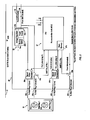
Figure 1 is a schematic of one embodiment of the module according to the invention, where operation of the module is controlled by a microcontroller with embedded flash memory. -
Figure 2 is a schematic of one embodiment of a smart socket according to the invention where operation of the smart socket is controller by a microcontroller with embedded flash memory. -
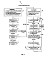
Figure 3 is a flowchart of one embodiment of a software flow chart for the microcontroller in the module ofFigure 1 . -
Figure 4 is a flowchart of one embodiment of a software flow chart for the microcontroller in the smart socket ofFigure 2 . -
Figure 5 is a timing diagram showing the key events in connecting the module ofFigure 1 between a plug-in vehicle and the smart socket ofFigure 2 , which forms a public or semi-public outlet. -
Figure 6 is a timing diagram showing the key events in connecting the module ofFigure 1 between a plug-in vehicle and a conventional socket, which forms a private outlet. -
Figure 7A is a side view of an embodiment of the smart socket with prongs for preventing unauthorized disconnection from the module. -
Figure 7B is a front view of an embodiment of the smart socket with prongs for preventing unauthorized disconnection from the module. -
Figure 7C is a top view of an embodiment of the smart socket with prongs for preventing unauthorized disconnection from the module and showing how the smart socket connects to the module. -
Figure 8A is a top view of an embodiment of the module with a tether cable and securing bracket for preventing unauthorized disconnect of the vehicle plug from the module. -
Figure 8B shows an embodiment of the securing bracket with non-standard screw heads. - Referring to
Figure 1 ,module 1 forms a connection between the vehicle's charging interface and an outlet that connects to the energy grid. In one implementation, as shown, a male plug from the vehicle's charging interface plugs into a correspondingfemale socket 13 on the module, and amale plug 12 on the module plugs into a corresponding female socket connected to the energy grid. - Microcontroller unit (MCU) 5, comprising
processor core 5a, embeddedflash memory 5b, analog to digital converter (ADC) (not shown), and several programmable input/output peripherals (not shown), controls module operation. In one embodiment, it also synchronizes the data retrieved from the energy sensor 10 (to be described later) prior to transmitting it to the local utility via the communications interface or BPL. A software flowchart depicting the operation of MCU 5 will be presented later. - The
flash memory 5b is non-volatile memory that stores certain pre-programmed information, such as the user's utility account information and access code, and also user preferences regarding energy pricing and desired charging times. This information may be pre-programmed into theflash memory 5b through a number of suitable means, including the Internet, a USB port (e.g., USB socket 7), thecommunications interface 16, which is described later, or BPL. -
Communications interface 16, comprising communication chip 8 and antenna 8, is configured, in one embodiment, to wirelessly communicate data from the MCU 5 to the local utility via the access point (i.e., meter) in the outlet owner's HAN using a suitable protocol, including but not limited to WiFi (802.15), ZigBee (802.15.4), WiMAX (8-2.16), satellite, and RF. In another embodiment, thecommunications interface 16 is configured to communicate data from the MCU 5 to the local utility via a wired link. The connection formed by communications interface may either be downlink only (i.e., from the module to the utility) or bi-directional. -
LED indicator 15 is configured to provide a visual indication when the module is waiting for the end user to authenticate himself/herself. - Security authentication device 6 is any suitable device for authenticating the identity of the end user. Options include a fingerprint reader, a password keypad, etc.
- User program selector 4 allows a user to set or change charging preferences (charge immediately, charge at certain time of day, respond to price signals, etc).
-
Energy sensor 10 is an IC that senses bi-directional energy flow through themodule 1 and outputs a digital signal indicative of a characteristic of the energy flow, e.g., amperage. This information is periodically transmitted to the MCU 5, which may in turn communicate the information to the local utility viacommunications interface 16. -
Signal power decoupler 2 separates the mixed power signal fromplug 12, which may either be inserted into a smart socket or a conventional socket, into a 110 V (60 Hz) AC power signal and data, if any, that was previously modulated onto the power signal and communicated via BPL (Broadband-Over-Power Line). As will be discussed, in the case where theplug 12 is connected to a smart socket, data communicated to themodule 1 via BPL comprises an identifier of the socket and its associated meter. - Signal power decoupler 11 combines the 110V, 60 Hz power signal with data, if any, to form a mixed signal that is communicated to the vehicle via the vehicle charging
interface socket 13. - The voltage regulator 3 regulates the DC voltage of
power supply 3c to maintain it at constant voltage level, Vcc. Thebackup battery 3b powers themodule 1 before energy flow from the energy grid is enabled. -
Switch 14 is normally open, but is closed only after the end user has been authenticated and the module has been enabled. -
Figure 2 is a schematic ofsmart socket 20, which embodies or functions as a public or semi-public outlet. It is used to connect themodule 1 to the energy grid in the first mode of operation. - As shown, in one implementation,
socket 20 comprises one or morefemale outlets male plug 12 from the module ofFigure 1 . Each of theoutlets - Microcontroller unit (MCU) 27, comprising
processor core 27a, embeddedflash memory 27b, analog to digital converter (ADC) (not shown), and several programmable input/output peripherals (not shown), controls socket operation. More specifically,MCU 27 is responsible for controlling the functionality of thesocket 20 when a module is connected to it, including communicating meter and socket identification information to the module via BPL. It also controls a relay (switches - The
voltage regulator 22 regulates the DC voltage ofpower supply 22c to maintain it at constant voltage level, Vcc. Thebackup battery 22b powers thesocket 20 before energy flow from the energy grid is enabled. -
Signal power decoupler 25a combines the 110V, 60 Hz grid live power signal fromline 23 with data, if any, fromMCU 27 to form a mixed signal that is communicated to themodule 1 overline 28a. -
Signal power decoupler 25b combines the 110V, 60 Hz grid neutral power signal fromline 24 with data, if any, fromMCU 27 to form a mixed signal that is communicated to themodule 1 vialine 29a. -
Figure 3 is an embodiment of asoftware flow chart 30 depicting the operation of MCU 5 inFigure 1 . As will be appreciated, this flow chart represents software, embodying a method of operation, that is stored in a medium that is readable by MCU 5, includingflash memory 5b, but also volatile memory, such as RAM, that may be loaded from theflash memory 5b upon power-up. - This flowchart depicts the first mode of operation, when the connection to the energy grid occurs by connecting the module to a public or semi-public outlet.
- In
block 31, the MCU 5 guides themodule 1 through initialization, which includes establishing a connection to the local utility through thecommunications interface 16, loading the program memory (i.e., RAM), with the MCU software, turning on theLED 15 to prompt the end user to authenticate himself/herself, and enabling the security authentication device 6 to receive input. In one embodiment, as discussed, the connection is a wireless connection that is established with an access point (i.e., the meter for the outlet) in the outlet owner's HAN. - From
block 31, the process proceeds to block 32. Inblock 32, the process loops, waiting for the end user to authenticate himself/herself via security authentication device 6 using a password, fingerprint, or other secure technique such as a biometric scan. Upon the user doing so, the process proceeds to block 33. - In
block 33, the module, via thecommunications interface 16, transmits user data (e.g., a unique access code associated with the user's account), that was pre-programmed and stored in theflash memory 5b, to the local utility via the communications interface (e.g., the HAN for the owner of the public or semi-public outlet). The process then proceeds to block 34.where the process waits for the utility to authenticate the user code. If the utility fails to authenticate the code, or affirmatively indicates that the code failed, i.e., by communicating a "failed" message via BPL to the module, the process outputs an error message, represented byblock 35. - However, if the utility authenticates the code, it communicates an "authorized" message to the module via BPL, and then jumps to block 36.
- In
block 36, the process checks to see if the module is being powered through the USB port 7, indicating that a host processor is coupled to the module. If so, as indicated inblock 37, the host operating system is given control of the module. - If, on the other hand, the module is intended to be AC-powered, the process jumps to block 38. In
block 38, pre-programmed information, if any, reflecting user preferences is retrieved and stored in memory, and data needed to implement those preferences, i.e., pricing, is requested from the utility, either via the communications interface 16 (if the connection is bi-directional) or BPL (if the connection viacommunications interface 16 is downlink-only). Fromblock 38, the process proceeds to block 39. - In
block 39, the module requests, via BPL, that the smart socket inform it of its identity and that of its related meter. If the request yields the desired information, the process then jumps to block 40. - In
block 40, the process stores this information within the module (i.e., within theflash memory 5b). The process then jumps to block 41. - In
block 41, the module requests, via BPL, thatMCU 27close switches - In
block 42, the module again requests utility authorization, and loops until the necessary authorization is received. Once the authorization is received, the process proceeds to block 43. - In block 43, the process checks whether the conditions implied by the pre-programmed user preferences, if any, have been satisfied. If so, the process jumps to block 45.
- In
block 45, MCU 5 is directed to close theswitch 14 within the module, thus enabling power to flow. The process then proceeds to block 46. - In
block 46, the module periodically senses data regarding energy flow through the module (via energy sensor 10), and transmits the same to the local utility via thecommunications interface 16 or BPL. The process then jumps back to block 43, whereupon it loops indefinitely throughblocks Figures 5-6 . -
Figure 4 is an embodiment of asoftware flow chart 50 forMCU 27 inFigure 2 . As will be appreciated, this flow chart represents software, embodying a method of operation, that is stored in a medium that is readable byMCU 27, includingflash memory 27b, but also volatile memory, such as RAM, that is loaded from theflash memory 5b upon power-up. - In
block 51, the smart socket waits for a request from the module for the identity of the socket and its associated meter. When such a request is received, the process proceeds to block 52. - In
block 52, theMCU 27 retrieves this information fromflash memory 27b, and communicates it to the module via BPL. Fromblock 52, the process proceeds to block 53. - In
block 53, the socket waits for an indication of utility authorization from the module. If such indication is obtained via BPL, the process proceeds to closeswitches block 54. The process then proceeds to block 55. - In
block 55, the socket periodically checks the status of the connection and the utility authorization. If the connection and the utility authorization are both intact, the process loops. If either the connection or the utility authorization is no longer intact, the process proceeds to block 56. - In
block 56, the process opensswitches - From
block 56, the process jumps back to block 51, where it waits for another request for socket and meter identity. -
Figure 5 is a timing diagram illustrating the timing of the key events in the overall process of connecting a plug-in vehicle to the energy grid through a public or semi-public outlet. As will be seen, some of these events are manual steps performed by the end user, and some are performed by the MCU's 5, 27 operating pursuant to the flow charts ofFigures 3-4 . - In
block 61, the user inserts the male plug from the vehicle's charging interface into the corresponding female socket on the module. - Then, in
block 62, the user activates the module after successfully authenticating himself/herself via security authentication device 6. - In
block 63, the user inserts the male plug from the module into the corresponding female socket of the public or semi-public outlet. - In
block 64, the module identifies the socket and the related meter. As previously explained, the module obtains this information from the socket via BPL, withFigure 4 depicting the process steps undertaken byMCU 27 in providing this information. - In
block 65, the module connects to the local utility via thecommunications interface 16. In one embodiment, as previously explained, the module connects via the access point (i.e., meter) for the outlet in the utility's Home Area Network (HAN). - In
block 66, the module identifies the vehicle as a plug-in vehicle and notifies the local utility of this identity through the connection established inblock 65. This information is needed for the purpose of obtaining advantageous energy pricing from the utility. - In
block 67, the local utility validates the module and the user account. As previously explained, this is accomplished by sending the local utility a unique access code for the user over the connection established inblock 65. Using this information, the utility validates the module and the user's account, and transmits the results of this validation (i.e., successful or not) back to the module via BPL or the connection established viacommunications interface 16. - Assuming the validation is successful, block 68 is performed. In
block 68, the module repeatedly checks for price signals from the local utility. The utility communicates this information to the module over the connection established inblock 65, assuming that connection is bi-directional, or via BPL. -
Block 69 followsblock 68. Inblock 69, the module responds to the price signals based on user preferences. For example, if the user has expressed a preference that charging not occur until the price of energy is at or below 10 cents per kilowatt hour, the module iterates until the price as reported from the utility meets this condition. At that point, the process proceeds to block 70. - In
block 70, the module directs the socket to close the socket switches (26a, 26b). In addition, if not already accomplished, the module closes themodule switch 14, allowing power to flow to the vehicle. - In
block 71, the module meters the consumption of energy and stores this information. - In
block 72, the end user unplugs the module from the socket when the charging session is over or the user wishes to terminate the charging session. - In
block 73, a breaker in the socket disconnects, openingswitches - In
block 74, the module sends the consumption data to the local utility through the connection established inblock 65. - In
block 75, the local utility calculates the amount owed for the energy consumption, using the preferred rates for electric vehicles. - In
block 76, the local utility charges the user's account with the amount calculated inblock 75. - In
block 77, the meter tied to the socket is credited with the amount calculated inblock 75. Then, theswitch 14 in the module is opened, disabling the module. -
Figure 6 is a timing diagram illustrating the timing of the key events in the overall process of connecting a plug-in vehicle to the energy grid through a private (i.e., home) outlet. As will be seen, some of these events are manual steps performed by the end user, and some are performed by the MCU's 5, 27 operating pursuant to the flow charts ofFigures 3-4 . - In
block 81, the user inserts the male plug from the vehicle's charging interface into the corresponding female socket on the module. - Then, in
block 82, the user activates the module after successfully authenticating himself/herself via security authentication device 6. - In
block 83, the user inserts the male plug from the module into the corresponding female socket of the home outlet. - In
block 84, the module identifies the vehicle as a plug-in vehicle and notifies the local utility of this identity. In one implementation, this is accomplished via BPL. This information is needed for the purpose of obtaining advantageous energy pricing from the utility. - In
block 85, the module repeatedly checks for price signals from the local utility. In one implementation, the utility communicates this information to the module via BPL. -
Block 86 followsblock 85. Inblock 86, the module responds to the price signals based on user preferences. For example, if the user has expressed a preference that charging not occur until the price of energy is at or below 10 cents per kilowatt hour, the module iterates until the price as reported from the utility meets this condition. At that point, the process proceeds to block 87. - In
block 87, the module directs the socket to close the socket switches (26a, 26b). In addition, if not already accomplished, the module closes themodule switch 14, allowing power to flow to the vehicle. - In
block 88, the module meters the consumption of energy and stores this information. - In
block 89, the module connects to the local utility via thecommunications interface 16. In one embodiment, as previously explained, the module connects via the access point (i.e., meter) for the user's outlet in the utility's Home Area Network (HAN). - In
block 90, the user unplugs the module from the socket when the charging session is over or the user wishes to terminate the charging session. In response, a breaker in the socket disconnects, openingswitches - In
block 91, energy flow to the vehicle ceases. - In
block 92, the module sends the consumption data to the local utility through the connection established inblock 89. - In
block 93, the local utility calculates the amount owed for the energy consumption, using the preferred rates for electric vehicles. - In
block 94, the local utility charges the user's account with the amount calculated inblock 93. - In
block 95, if the user account differs from the meter account for the meter tied to the user outlet, the meter account is credited with the amount calculated inblock 93. Then, theswitch 14 in the module is opened, disabling the module. - As can be seen from the foregoing, the main differences between the overall processes depicted in
Figures 5-6 is thatblock Figure 5 (public use) are eliminated from the process depicted inFigure 6 (home use). These steps, where the module identifies the public or semi-public socket and related meter (block 64), and the local utility validates the module and the user account (block 67), are unnecessary in the process depicted inFigure 6 , where the user connects the module to a private outlet or socket in the user's own residence. - Preferably, the smart socket and module of the invention includes mechanisms for preventing unauthorized removal of the module from the smart socket during charging in order to prevent malicious or accidental tampering, unauthorized use of the module, or energy theft. Referring to
Figures 7A-C ,smart socket 20 may includeprongs 104 that extend outwardly from thesmart socket 20 and includemechanisms 105 such asretractable barbs 105 that prevent removal of themodule 1 from thesmart socket 20 during charging. Theprongs 104 withretractable barbs 105 are preferably placed in close proximity to plugreceptacles module 1 includesfemale receptacles 107 that accommodate theprongs 104 when thebarbs 105 are retracted, but do not allow thesocket 20 to be removed when thebarbs 105 are extended. Thefemale receptacles 107 are placed in the same relative proximity to theplugs prongs 104 are to theplug receptacles - The
retractable barbs 105 allow a locking connection between thesmart socket 20 and themodule 1 that is activated, for example, after the user has been authenticated during charging. Theretractable barbs 105 may automatically retract once the charge is complete and thesmart socket 20 deactivates the flow of electricity to themodule 1. Alternatively, the user may manually stop the charging process and thus retract theretractable barbs 105. Preferably, the user must be authenticated using the aforementioned systems and methods in order to disengage thebarbs 105 and thus release themodule 1 from thesmart socket 20. While this embodiment shows theprongs 104 withbarbs 105 attached to thesmart socket 20, in alternative embodiments, the locking mechanism may be part of themodule 1 instead of or in addition to the locking mechanism described as part of thesmart socket 20. - It is also preferable to include a mechanism to prevent unintentional or unauthorized disconnection of a vehicle plug from the
module 1. For example, a vehicle plug may be stepped on or kicked during charging, preventing the vehicle from receiving an adequate charge.Figures 8A and 8B show an embodiment that includes atether cable 112 and securingbracket 111 that prevents unintentional or unauthorized disconnection of thevehicle plug 110 from themodule 1. In a preferred embodiment, the securingbracket 111 is secured to thevehicle plug 110 using screws or fasteners with non-standard heads to prevent unauthorized users from disconnecting the securingbracket 111 from thevehicle plug 110 and disconnecting thevehicle plug 110 from themodule 1. The authorized user may be provided a tool that fits the non-standard screw heads to fasten or release the securingbracket 111 from thevehicle plug 110. In other embodiments, the securingbracket 111 may be fitted with a lock and only the authorized user is provided a key that opens the lock. - In light of the foregoing, it can be seen that a modularized interface, comprising a module and a smart socket for public use, for connecting a plug-in vehicle to the energy grid is provided that has the following advantages and benefits:
- A key issue for enabling public charging of electric vehicles is the ability to identify the energy user so that billing for electricity costs can be appropriately applied. As discussed, the inventive modularized interface contains a communication chip which will communicate with the local electric utility's Advanced Metering Infrastructure (AMI) Home Area Network (HAN). The module in this interface is programmed with the user's local electric utility account information or other billing information. This account information is transmitted via the communication interface to the HAN of the owner of the public electrical outlet and on to the local utility. The electricity which passes through the module is metered by the module. Upon disconnect, the metered data, including both time of use and consumption, is transmitted through the HAN connection to the local utility so that it can be billed to the energy user's local utility account. The utility meter through which the energy was drawn is then credited with an offsetting amount.
- Ensuring that publicly available electric vehicle outlets do not expose outlet owners to energy theft is another key issue. The inventive modularized interface secures energy usage through these means:
- The module within the interface must be enabled at each use by the module owner (energy user). The module is equipped with user validation (password or other secure technique, such as biometric scan). The enabled module will communicate a unique access code to the HAN of the public electric vehicle outlet. The local utility will validate the code (tied to the module owner's utility account or other billing mechanism). Once validated, the utility will signal the public electric vehicle outlet to enable energy to flow to the module. Each smart socket will have remotely enabled on/off functionality built in. Once the flow of energy is broken (the module or vehicle is unplugged) the smart socket and the module are disabled. This automatic disabling will disable theft of electricity and deter theft of the modules since they will not be usable by anyone other than the module owner. An optional anti-theft feature is to enable the module to physically lock on to the plug from the vehicle so it can only be removed with a key or user validation (password or other secure technique, such as biometric scan).
- The modules (user validation and utility account information) are initially programmed through a technique similar to USB-to-computer or module communication-to-HAN internet connection by the module owner in conjunction with the local utility. Re-programming the module must be done by the local utility and is only done after verification of the identity of the owner.
- Public electric vehicle outlets will be made available by local governments, and property and business owners. Availability of outlets may be driven by public policy or the desire to encourage electric vehicle owners to work for or do business with a particular business. For example, shopping malls may install outlets to make their stores a more attractive place at which to shop.
- The smart sockets will be in range of the HAN, or if not, will be equipped with their own communication device which will act as a bridge between the module and the HAN. Alternatively, other communications interfaces may be used. As mentioned above, each smart socket will have remote connect/disconnect functionality through a unique identifier built in and controlled by the local utility.
- Owners of electric vehicle who reside in multi-family units may not have private access to electrical outlets to charge their vehicles. Using the security features of the inventive modularized interface enables an outlet or bank of outlets to be installed in apartment/condominium parking areas with energy charges billed to the car owner.
- While electric vehicle owners will not need to use the module to charge their cars at their own homes, they may be given incentive to do so by the local utility through special, reduced electric vehicle charging rates. Utilities will likely offer these rates during off-peak electricity demand periods. In this scenario, the module will communicate with the HAN, identifying the charging device as a vehicle which is eligible for electric vehicle rates. The module will confirm the device as a vehicle through the vehicle's built-in VIN chip or through the high amperage required for vehicle charging.
- The inventive modularized interface will allow electric vehicle owners to take advantage of off-peak electricity pricing. The module includes a timing device which is programmed through an Internet interface to allow vehicle charging at times set by the vehicle owner. Additionally, if price signals are available from the local utility through the HAN, the module can be programmed to respond to price signals at the vehicle owner's preference.
- When vehicles are connected to the electricity grid through an inventive module, they are readily identified as electric vehicles by the local utility. If electric vehicles are charging during critical periods of peak demand the local utility or other controlling entity will be able to remotely discontinue charging by disabling the public electric vehicle outlet or, if charging at a private residence, opening the electric circuit within the module.
- In some circumstances, it may be financially compelling for electric vehicle owners to sell stored electricity from their vehicle to the local electric utility. In this case, the inventive module can, through the HAN, instruct the utility to reverse the flow of power through any uniquely identified electric vehicle outlet. The amount of energy provided to the utility will be metered by the module and the car owner's utility account will be credited appropriately.
- Although the invention has been described with reference to the presently preferred embodiments, it should be understood that various modifications could be made without departing from the scope of the invention.
Claims (15)
- A modularized interface for connecting a plug-in electric vehicle to the energy grid comprising:a module integrated within or configured to be connected to a charging interface on the vehicle, and also configured to be connected to a socket connected to the energy grid, comprising:a security authentication device for authenticating and authorizing an end user;a communications interface for forming a connection to a local utility;a processor for controlling operation of the module;a switch that, when open, disables the module from delivering power to the vehicle, and, when closed, enables the module to deliver power to the vehicle;wherein the processor controls the module so that the module is normally disabled, and is enabled only after the module is authenticated using the security authentication device, and the utility authorizes the module, and the end user's account or other billing/credit or payment provision is charged using the connection established via the communications interface;wherein the processor within the module meters energy consumption or discharge while energy flows to or from the vehicle and the time of day or time interval that consumption or discharge occurs through the modularized interface; andwherein, when the module is disconnected from the socket, the processor within the module, after communicating the metered data to the local utility over the connection established via the communications interface, disables the module.
- The modularized interface of claim 1, wherein the connection to the local utility takes place through the utility's Home Area Network or other communication interface and the socket is a smart socket comprising:at least one switch that, when open, disables the smart socket from delivering power to the vehicle, and, when closed, enables the smart socket to deliver power to the vehicle through the module; anda processor for controlling operation of the smart socket so that:the smart socket is normally disabled, and is enabled only after the module, after being connected to the smart socket, identifies the smart socket and its associated meter, and user preferences, if any, regarding energy pricing or charging scheduling, pre-programmed into the module, are satisfied; andwhen the module is disconnected from the socket the processor within the smart socket disables the smart socket.
- The modularized interface of claim 1 or claim 2, wherein the processor receives periodic price signals from the utility over the communication interface and adjusts charging or discharging according to preferences defined by the user.
- The modularized interface of any preceding claim, wherein the utility disables or enables charging or discharging by the module by sending a signal over the communication interface.
- The modularized interface of any preceding claim, further comprising a locking mechanism for preventing unauthorized disconnection between the module and the socket when the socket and module are enabled.
- The modularized interface of claim 5, wherein the security authentication device disengages the locking mechanism.
- The modularized interface of any preceding claim, further comprising a securing bracket for preventing a vehicle plug from being disconnected from the module.
- A modularized interface for connecting a plug-in electric vehicle to the energy grid comprising:a smart socket connected to the energy grid and configured to be connected to a module integrated within or configured to be connected to a charging interface on the vehicle, the smart socket comprising:a processor for controlling operation of the smart socket;at least one switch that, when open, disables the smart socket from delivering power to the vehicle, and, when closed, enables the smart socket to deliver power to the vehicle through the module;wherein the processor controls the smart socket so that the smart socket is normally disabled, and is enabled only after the module, after being connected to the smart socket, identifies the smart socket and its associated meter, and user preferences, if any, regarding energy pricing or charging scheduling, pre-programmed into the module, are satisfied;wherein, when the module is disconnected from the smart socket, the processor within the smart socket disables the smart socket.
- A process for connecting a plug-in electric vehicle to the energy grid through an interface, comprising a module and a socket that is connected to the energy grid, comprising the steps of:authenticating and authorizing an end user using a security authentication device within the interface;enabling the module only after the module is connected to the socket, the end user is authenticated and authorized using the security authentication device;enabling energy to flow to the vehicle, only after the user is authenticated and authorized and any user preferences regarding energy pricing or charging scheduling, pre-programmed into the module, are satisfied;metering energy consumption while energy flows to the vehicle through the interface;forming a communications interface to the local utility; andwhen the module is disconnected from the socket, communicating the metered data to the local utility over the connection established via the communications interface, and disabling the module.
- The process of claim 9, wherein:the socket is a smart socket;the module is configured to be connected to a charging interface on the vehicle and to the smart socket;the connection to the local utility is formed through the utility's Home Area Network or other communications interface;authenticating the module and the end user's account takes place using the connection established via the communications interface;the smart socket is enabled only after the module identifies the smart socket and its associated meter; andwhen the module is disconnected from the socket the smart socket is disabled.
- The process of claim 11 or claim 12, further comprising locking the module to the socket when the socket and module are enabled.
- The process of claim 11, further comprising disengaging the locking mechanism only after the end user is authenticated.
- The process of any of claims 9 to 12, further comprising receiving periodic price signals from the utility over the communication interface and adjusting charging or discharging according to preferences defined by the user.
- The process of any of claims 9 to 13, further comprising disabling or enabling charging or discharging by the module by sending a signal over the communications interface.
- The process of any of claims 9 to 14, wherein the interface is an off-vehicle modularized interface.
Applications Claiming Priority (2)
| Application Number | Priority Date | Filing Date | Title |
|---|---|---|---|
| US9049208P | 2008-08-20 | 2008-08-20 | |
| US12/265,678 US8736225B2 (en) | 2008-08-20 | 2008-11-05 | Modularized interface and related method for connecting plug-in electric vehicles to the energy grid |
Publications (2)
| Publication Number | Publication Date |
|---|---|
| EP2156978A2 true EP2156978A2 (en) | 2010-02-24 |
| EP2156978A3 EP2156978A3 (en) | 2015-12-09 |
Family
ID=41508069
Family Applications (1)
| Application Number | Title | Priority Date | Filing Date |
|---|---|---|---|
| EP09168340.9A Withdrawn EP2156978A3 (en) | 2008-08-20 | 2009-08-20 | Modularized interface and related method for connecting plug-in electric vehicles to the energy grid |
Country Status (3)
| Country | Link |
|---|---|
| US (1) | US8736225B2 (en) |
| EP (1) | EP2156978A3 (en) |
| CA (1) | CA2676466C (en) |
Cited By (12)
| Publication number | Priority date | Publication date | Assignee | Title |
|---|---|---|---|---|
| FR2962862A1 (en) * | 2010-07-16 | 2012-01-20 | Valeo Securite Habitacle | Motor vehicle's i.e. electric or hybrid motor vehicle, electric charge managing method, involves scheduling charge of motor vehicle for attaining requested level of charge based on electric tariff and limited charge duration fixed by user |
| WO2012042134A1 (en) | 2010-10-01 | 2012-04-05 | Compagnie Nationale Du Rhone - Cnr | Self-contained device and system for regulating the charging of internal storage means in an electric vehicle |
| WO2013062453A1 (en) * | 2011-10-25 | 2013-05-02 | Telefonaktiebolaget L M Ericsson (Publ) | Charging an energy storage unit |
| ES2400524R1 (en) * | 2011-03-04 | 2013-06-19 | Nomantica S L | MOBILE PLATFORM FOR SMART RECHARGE OF ELECTRIC VEHICLES |
| EP2562729A3 (en) * | 2011-08-23 | 2013-10-09 | General Electric Company | System and method for use when charging an electrically powered vehicle |
| FR2990811A1 (en) * | 2012-05-21 | 2013-11-22 | John Honore | TERMINAL AND RECHARGEABLE INSTALLATION FOR ELECTRIC VEHICLE, CORRESPONDING MANAGEMENT METHOD AND COMPUTER PROGRAM. |
| US8872667B2 (en) | 2011-09-13 | 2014-10-28 | International Business Machines Corporation | Fault isolation and service restoration in an electric grid |
| US9672576B2 (en) | 2011-09-13 | 2017-06-06 | International Business Machines Corporation | System and method for enabling effective work force management of a smart grid |
| WO2018115363A1 (en) * | 2016-12-21 | 2018-06-28 | University College Dublin, National University Of Ireland, Dublin | Pricing adapter for domestic electric vehicle charging stations |
| US10714935B2 (en) | 2011-01-04 | 2020-07-14 | International Business Machines Corporation | Subscriber-driven system for managing events in an electrical grid |
| WO2022157658A3 (en) * | 2021-01-20 | 2023-02-23 | Trigoso Papoila Antonio Luis | System for charging electric vehicles with shared resources |
| FR3134764A1 (en) * | 2022-04-22 | 2023-10-27 | Psa Automobiles Sa | ELECTRIC PLUG |
Families Citing this family (64)
| Publication number | Priority date | Publication date | Assignee | Title |
|---|---|---|---|---|
| US8890505B2 (en) | 2007-08-28 | 2014-11-18 | Causam Energy, Inc. | System and method for estimating and providing dispatchable operating reserve energy capacity through use of active load management |
| US8806239B2 (en) | 2007-08-28 | 2014-08-12 | Causam Energy, Inc. | System, method, and apparatus for actively managing consumption of electric power supplied by one or more electric power grid operators |
| US9130402B2 (en) | 2007-08-28 | 2015-09-08 | Causam Energy, Inc. | System and method for generating and providing dispatchable operating reserve energy capacity through use of active load management |
| US12438368B2 (en) | 2007-08-28 | 2025-10-07 | Causam Enterprises, Inc. | System and method for estimating and providing dispatchable operating reserve energy capacity through use of active load management |
| US8805552B2 (en) | 2007-08-28 | 2014-08-12 | Causam Energy, Inc. | Method and apparatus for actively managing consumption of electric power over an electric power grid |
| US9177323B2 (en) | 2007-08-28 | 2015-11-03 | Causam Energy, Inc. | Systems and methods for determining and utilizing customer energy profiles for load control for individual structures, devices, and aggregation of same |
| US20100094737A1 (en) * | 2008-08-18 | 2010-04-15 | Bryan Lambird | Utility communications design concept |
| US9047494B1 (en) * | 2008-09-08 | 2015-06-02 | United Services Automobile Association | System and method for disabling and/or enabling a device |
| US20100063645A1 (en) * | 2008-09-09 | 2010-03-11 | Brown Stephen J | Load balancing based on user input |
| US8315930B2 (en) * | 2008-12-22 | 2012-11-20 | General Electric Company | Systems and methods for charging an electric vehicle using broadband over powerlines |
| US20100161469A1 (en) * | 2008-12-22 | 2010-06-24 | Nathan Bowman Littrell | Systems and methods for charging an electric vehicle using a wireless communication link |
| US8583551B2 (en) | 2008-12-22 | 2013-11-12 | General Electric Company | Systems and methods for prepaid electric metering for vehicles |
| US9396462B2 (en) * | 2008-12-22 | 2016-07-19 | General Electric Company | System and method for roaming billing for electric vehicles |
| US9030153B2 (en) | 2008-12-22 | 2015-05-12 | General Electric Company | Systems and methods for delivering energy to an electric vehicle with parking fee collection |
| US20100161517A1 (en) * | 2008-12-22 | 2010-06-24 | Nathan Bowman Littrell | Systems and methods for electricity metering for vehicular applications |
| US20100161518A1 (en) * | 2008-12-22 | 2010-06-24 | Nathan Bowman Littrell | Electricity storage controller with integrated electricity meter and methods for using same |
| US9505317B2 (en) * | 2008-12-22 | 2016-11-29 | General Electric Company | System and method for electric vehicle charging and billing using a wireless vehicle communication service |
| US20100198751A1 (en) * | 2009-02-03 | 2010-08-05 | Cybernet Systems Corporation | Plug-in hybrid recharge power system |
| US8089747B2 (en) * | 2009-05-22 | 2012-01-03 | Eaton Corporation | Power pedestal and system employing same |
| US20110145141A1 (en) * | 2009-10-02 | 2011-06-16 | James Blain | Method and apparatus for recharging electric vehicles |
| DE102009045639A1 (en) * | 2009-10-13 | 2011-04-14 | Robert Bosch Gmbh | Electrical connection device for hybrid and electric vehicles and associated method for charging |
| US8558504B2 (en) | 2010-01-11 | 2013-10-15 | Leviton Manufacturing Co., Inc. | Electric vehicle supply equipment with timer |
| US9299093B2 (en) * | 2010-01-29 | 2016-03-29 | GM Global Technology Operations LLC | Method for charging a plug-in electric vehicle |
| US9156362B2 (en) | 2010-04-09 | 2015-10-13 | Aerovironment, Inc. | Portable charging cable with in-line controller |
| KR101132948B1 (en) * | 2010-05-13 | 2012-04-05 | 엘에스산전 주식회사 | System, Apparatus and Method for Charge and Discharge Control of Electric Vehicle |
| US8725330B2 (en) | 2010-06-02 | 2014-05-13 | Bryan Marc Failing | Increasing vehicle security |
| USD632645S1 (en) | 2010-06-25 | 2011-02-15 | James Blain | Vehicle recharge station |
| US20120217928A1 (en) * | 2011-02-28 | 2012-08-30 | Juice Technologies Llc | Electric vehicle charging interface |
| US9371007B1 (en) * | 2011-04-22 | 2016-06-21 | Angel A. Penilla | Methods and systems for automatic electric vehicle identification and charging via wireless charging pads |
| US8823330B2 (en) | 2011-04-29 | 2014-09-02 | General Electric Company | Charging systems for use with electric vehicles and methods of monitoring same |
| US8854000B2 (en) * | 2011-06-01 | 2014-10-07 | GM Global Technology Operations LLC | Rapid energy recharge system for a battery electric vehicle |
| US8798805B2 (en) * | 2011-07-27 | 2014-08-05 | General Electric Company | Electric vehicle charging station remote disconnect system |
| US9207735B2 (en) * | 2011-08-02 | 2015-12-08 | Gram Power, Inc. | Power management device and system |
| US20130041851A1 (en) * | 2011-08-10 | 2013-02-14 | International Business Machines Corporation | Implementing direct energy metering, authentication and user billing |
| US8692561B2 (en) | 2011-08-11 | 2014-04-08 | International Business Machines Corporation | Implementing chip to chip calibration within a TSV stack |
| US9156368B2 (en) * | 2011-11-11 | 2015-10-13 | San Diego Gas & Electric Company | Method for detection of plug-in electric vehicle charging via interrogation of smart meter data |
| US8781639B2 (en) * | 2012-01-12 | 2014-07-15 | Max Li | Digital wireless network receptacle |
| US20130211885A1 (en) * | 2012-02-10 | 2013-08-15 | Electric Transportation Engineering Corporation d/b/a ECOtality North America | Electricity Transfer System and Method of Providing and Using the Same |
| JP5891949B2 (en) * | 2012-05-25 | 2016-03-23 | ソニー株式会社 | Information processing apparatus, connection device, communication device, information processing method, and program |
| US9207698B2 (en) | 2012-06-20 | 2015-12-08 | Causam Energy, Inc. | Method and apparatus for actively managing electric power over an electric power grid |
| US9461471B2 (en) | 2012-06-20 | 2016-10-04 | Causam Energy, Inc | System and methods for actively managing electric power over an electric power grid and providing revenue grade date usable for settlement |
| US9465398B2 (en) | 2012-06-20 | 2016-10-11 | Causam Energy, Inc. | System and methods for actively managing electric power over an electric power grid |
| US9563215B2 (en) | 2012-07-14 | 2017-02-07 | Causam Energy, Inc. | Method and apparatus for actively managing electric power supply for an electric power grid |
| US8849715B2 (en) | 2012-10-24 | 2014-09-30 | Causam Energy, Inc. | System, method, and apparatus for settlement for participation in an electric power grid |
| US8983669B2 (en) | 2012-07-31 | 2015-03-17 | Causam Energy, Inc. | System, method, and data packets for messaging for electric power grid elements over a secure internet protocol network |
| US9513648B2 (en) | 2012-07-31 | 2016-12-06 | Causam Energy, Inc. | System, method, and apparatus for electric power grid and network management of grid elements |
| US11830069B2 (en) | 2014-01-02 | 2023-11-28 | Causam Enterprises, Inc. | Systems and methods for electric vehicle charging and user interface therefor |
| US10899235B2 (en) | 2014-01-02 | 2021-01-26 | Causam Energy, Inc. | Systems and methods for electric vehicle charging and user interface therefor |
| US10116560B2 (en) | 2014-10-20 | 2018-10-30 | Causam Energy, Inc. | Systems, methods, and apparatus for communicating messages of distributed private networks over multiple public communication networks |
| US10769734B2 (en) | 2015-01-13 | 2020-09-08 | Causam Energy, Inc. | Systems and methods for advanced energy settlements, network-based messaging, and software applications for electric power grids, microgrids, grid elements, and/or electric power networks |
| US10474823B2 (en) | 2016-02-16 | 2019-11-12 | Atmel Corporation | Controlled secure code authentication |
| US10482255B2 (en) | 2016-02-16 | 2019-11-19 | Atmel Corporation | Controlled secure code authentication |
| US10616197B2 (en) | 2016-04-18 | 2020-04-07 | Atmel Corporation | Message authentication with secure code verification |
| JP2019092279A (en) * | 2017-11-14 | 2019-06-13 | トヨタ自動車株式会社 | Vehicle and power facility |
| US10796029B2 (en) | 2017-11-30 | 2020-10-06 | International Business Machines Corporation | Software controlled port locking mechanisms |
| DE102018102677B4 (en) * | 2018-02-07 | 2025-10-02 | Kromberg & Schubert Gmbh & Co. Kg | Procedure for releasing a function of a system and associated system |
| US10919405B2 (en) * | 2018-07-26 | 2021-02-16 | Swiftmile, Inc. | Light electric vehicle parking and charging stations and smart charging systems for the vehicle batteries |
| DE102019107071A1 (en) * | 2019-03-20 | 2020-09-24 | Innogy Se | Charging station for charging electric vehicles |
| TWI797312B (en) * | 2019-04-15 | 2023-04-01 | 拓連科技股份有限公司 | Systems and methods for charging management of charging devices |
| CA3092410A1 (en) | 2019-09-06 | 2021-03-06 | Parkizio Technologies Ltd. | Smart electrical outlet |
| US12592575B2 (en) | 2019-09-06 | 2026-03-31 | Parkizio Technologies Ltd. | Smart electrical outlet for monitoring and tracking electricity usage |
| LU500996B1 (en) * | 2021-12-12 | 2023-06-12 | Eclever Entw Ohg | SOCKET PROTECTION DEVICE |
| CN114379392B (en) * | 2022-03-24 | 2022-06-07 | 长安新能源南京研究院有限公司 | Intelligent lock control method and device for electric vehicle charging gun and storage medium |
| US20240256657A1 (en) * | 2023-01-26 | 2024-08-01 | Dell Products L.P. | System and method for intrusion detection in modular systems |
Family Cites Families (21)
| Publication number | Priority date | Publication date | Assignee | Title |
|---|---|---|---|---|
| US5627448A (en) * | 1993-04-22 | 1997-05-06 | Sumitomo Wiring Systems, Ltd. | Electric vehicle charging connector assembly |
| DE19609571A1 (en) * | 1995-11-20 | 1997-05-22 | Sihn Jr Kg Wilhelm | Coaxial connector for communication technology in automobiles |
| DE19642687C2 (en) * | 1996-10-16 | 1999-08-05 | Daimler Chrysler Ag | Locking device for securing a charging socket |
| JP3717420B2 (en) * | 2001-04-27 | 2005-11-16 | シャープ株式会社 | Mobile outlet, power supply gate device, server device, and power usage management system |
| US6614204B2 (en) * | 2001-12-21 | 2003-09-02 | Nicholas J. Pellegrino | Charging station for hybrid powered vehicles |
| JP4591823B2 (en) * | 2005-03-15 | 2010-12-01 | 東京電力株式会社 | Power supply system |
| JP4353197B2 (en) * | 2006-03-13 | 2009-10-28 | トヨタ自動車株式会社 | Vehicles and electrical equipment |
| US7747739B2 (en) * | 2006-08-10 | 2010-06-29 | Gridpoint, Inc. | Connection locator in a power aggregation system for distributed electric resources |
| US20080040295A1 (en) * | 2006-08-10 | 2008-02-14 | V2 Green, Inc. | Power Aggregation System for Distributed Electric Resources |
| US20080040263A1 (en) * | 2006-08-10 | 2008-02-14 | V2 Green, Inc. | Business Methods in a Power Aggregation System for Distributed Electric Resources |
| US20080052145A1 (en) * | 2006-08-10 | 2008-02-28 | V2 Green, Inc. | Power Aggregation System for Distributed Electric Resources |
| US20080040223A1 (en) * | 2006-08-10 | 2008-02-14 | V2 Green Inc. | Electric Resource Module in a Power Aggregation System for Distributed Electric Resources |
| US20080040296A1 (en) * | 2006-08-10 | 2008-02-14 | V2 Green Inc. | Electric Resource Power Meter in a Power Aggregation System for Distributed Electric Resources |
| US7844370B2 (en) * | 2006-08-10 | 2010-11-30 | Gridpoint, Inc. | Scheduling and control in a power aggregation system for distributed electric resources |
| US7949435B2 (en) * | 2006-08-10 | 2011-05-24 | V2Green, Inc. | User interface and user control in a power aggregation system for distributed electric resources |
| US20080039979A1 (en) * | 2006-08-10 | 2008-02-14 | V2 Green Inc. | Smart Islanding and Power Backup in a Power Aggregation System for Distributed Electric Resources |
| US20090192927A1 (en) * | 2006-09-13 | 2009-07-30 | Berg Michel J | Enhanced power outlet system incorporating a smart receptacle |
| US20080249965A1 (en) * | 2007-03-14 | 2008-10-09 | V2Green, Inc. | System and Apparatus for Collecting and Distributing Voluntary Environmental Impact Offset Payments on Fuel Purchases at Point of Sale |
| US7642670B2 (en) * | 2007-08-13 | 2010-01-05 | Glenn Rosendahl | Controlling power supply to vehicles through a series of electrical outlets |
| JP4379823B2 (en) * | 2007-09-25 | 2009-12-09 | 株式会社デンソー | Vehicle charging system |
| US7956570B2 (en) * | 2008-01-07 | 2011-06-07 | Coulomb Technologies, Inc. | Network-controlled charging system for electric vehicles |
-
2008
- 2008-11-05 US US12/265,678 patent/US8736225B2/en active Active
-
2009
- 2009-08-20 CA CA2676466A patent/CA2676466C/en active Active
- 2009-08-20 EP EP09168340.9A patent/EP2156978A3/en not_active Withdrawn
Non-Patent Citations (1)
| Title |
|---|
| None * |
Cited By (16)
| Publication number | Priority date | Publication date | Assignee | Title |
|---|---|---|---|---|
| FR2962862A1 (en) * | 2010-07-16 | 2012-01-20 | Valeo Securite Habitacle | Motor vehicle's i.e. electric or hybrid motor vehicle, electric charge managing method, involves scheduling charge of motor vehicle for attaining requested level of charge based on electric tariff and limited charge duration fixed by user |
| WO2012042134A1 (en) | 2010-10-01 | 2012-04-05 | Compagnie Nationale Du Rhone - Cnr | Self-contained device and system for regulating the charging of internal storage means in an electric vehicle |
| FR2965680A1 (en) * | 2010-10-01 | 2012-04-06 | Cie Nationale Du Rhone Cnr | AUTONOMOUS DEVICE AND SYSTEM FOR CONTROLLING THE LOAD OF INTERNAL STORAGE MEANS OF AN ELECTRIC VEHICLE |
| US10714935B2 (en) | 2011-01-04 | 2020-07-14 | International Business Machines Corporation | Subscriber-driven system for managing events in an electrical grid |
| ES2400524R1 (en) * | 2011-03-04 | 2013-06-19 | Nomantica S L | MOBILE PLATFORM FOR SMART RECHARGE OF ELECTRIC VEHICLES |
| EP2562729A3 (en) * | 2011-08-23 | 2013-10-09 | General Electric Company | System and method for use when charging an electrically powered vehicle |
| US8872667B2 (en) | 2011-09-13 | 2014-10-28 | International Business Machines Corporation | Fault isolation and service restoration in an electric grid |
| US9672576B2 (en) | 2011-09-13 | 2017-06-06 | International Business Machines Corporation | System and method for enabling effective work force management of a smart grid |
| US9785129B2 (en) | 2011-09-13 | 2017-10-10 | International Business Machines Corporation | Fault isolation and service restoration in an electric grid |
| US10007243B2 (en) | 2011-09-13 | 2018-06-26 | International Business Machines Corporation | Fault isolation and service restoration in an electric grid |
| WO2013062453A1 (en) * | 2011-10-25 | 2013-05-02 | Telefonaktiebolaget L M Ericsson (Publ) | Charging an energy storage unit |
| WO2013175113A1 (en) * | 2012-05-21 | 2013-11-28 | Honore John | Recharging terminal and facility for electric vehicle, corresponding management method and computer program |
| FR2990811A1 (en) * | 2012-05-21 | 2013-11-22 | John Honore | TERMINAL AND RECHARGEABLE INSTALLATION FOR ELECTRIC VEHICLE, CORRESPONDING MANAGEMENT METHOD AND COMPUTER PROGRAM. |
| WO2018115363A1 (en) * | 2016-12-21 | 2018-06-28 | University College Dublin, National University Of Ireland, Dublin | Pricing adapter for domestic electric vehicle charging stations |
| WO2022157658A3 (en) * | 2021-01-20 | 2023-02-23 | Trigoso Papoila Antonio Luis | System for charging electric vehicles with shared resources |
| FR3134764A1 (en) * | 2022-04-22 | 2023-10-27 | Psa Automobiles Sa | ELECTRIC PLUG |
Also Published As
| Publication number | Publication date |
|---|---|
| US20100045232A1 (en) | 2010-02-25 |
| CA2676466C (en) | 2018-08-07 |
| EP2156978A3 (en) | 2015-12-09 |
| US8736225B2 (en) | 2014-05-27 |
| CA2676466A1 (en) | 2010-02-20 |
Similar Documents
| Publication | Publication Date | Title |
|---|---|---|
| CA2676466C (en) | Modularized interface and related method for connecting plug-in electric vehicles to the energy grid | |
| US20120217928A1 (en) | Electric vehicle charging interface | |
| ES2966072T3 (en) | Electric vehicle to electric vehicle charging | |
| CN107210566B (en) | User authentication socket or connector, electric power proxy program and power consumption device | |
| US7984852B2 (en) | Recharge electrical apparatus and method for electric vehicles | |
| US9156365B2 (en) | Device and method for controlled exchange of energy between an electrical power network and a load | |
| EP2364874A2 (en) | An authentication system for a plug-in electric drive vehicle | |
| US20110022222A1 (en) | Charging system of electric powered vehicle | |
| JP2010110044A (en) | Charging equipment for electric vehicles | |
| US9677909B2 (en) | Electricity meter | |
| HK1141495A (en) | Modularized interface and related method for connecting plug-in electric vehicles to the energy grid | |
| KR20210075335A (en) | A mobile charging system that combines alternating current single-phase and three-phase based on internal batteries to satisfy both fast charging speed and charging accessibility |
Legal Events
| Date | Code | Title | Description |
|---|---|---|---|
| PUAI | Public reference made under article 153(3) epc to a published international application that has entered the european phase |
Free format text: ORIGINAL CODE: 0009012 |
|
| AK | Designated contracting states |
Kind code of ref document: A2 Designated state(s): AT BE BG CH CY CZ DE DK EE ES FI FR GB GR HR HU IE IS IT LI LT LU LV MC MK MT NL NO PL PT RO SE SI SK SM TR |
|
| AX | Request for extension of the european patent |
Extension state: AL BA RS |
|
| REG | Reference to a national code |
Ref country code: HK Ref legal event code: DE Ref document number: 1141495 Country of ref document: HK |
|
| PUAL | Search report despatched |
Free format text: ORIGINAL CODE: 0009013 |
|
| AK | Designated contracting states |
Kind code of ref document: A3 Designated state(s): AT BE BG CH CY CZ DE DK EE ES FI FR GB GR HR HU IE IS IT LI LT LU LV MC MK MT NL NO PL PT RO SE SI SK SM TR |
|
| AX | Request for extension of the european patent |
Extension state: AL BA RS |
|
| RIC1 | Information provided on ipc code assigned before grant |
Ipc: B60L 11/18 20060101AFI20151104BHEP |
|
| 17P | Request for examination filed |
Effective date: 20160609 |
|
| RBV | Designated contracting states (corrected) |
Designated state(s): AT BE BG CH CY CZ DE DK EE ES FI FR GB GR HR HU IE IS IT LI LT LU LV MC MK MT NL NO PL PT RO SE SI SK SM TR |
|
| 17Q | First examination report despatched |
Effective date: 20170419 |
|
| STAA | Information on the status of an ep patent application or granted ep patent |
Free format text: STATUS: THE APPLICATION IS DEEMED TO BE WITHDRAWN |
|
| REG | Reference to a national code |
Ref country code: HK Ref legal event code: WD Ref document number: 1141495 Country of ref document: HK |
|
| 18D | Application deemed to be withdrawn |
Effective date: 20181117 |