EP2155555B1 - A mounting element for a gas turbine engine, and a structure and an aircraft with such a mounting element - Google Patents
A mounting element for a gas turbine engine, and a structure and an aircraft with such a mounting element Download PDFInfo
- Publication number
- EP2155555B1 EP2155555B1 EP08767057.6A EP08767057A EP2155555B1 EP 2155555 B1 EP2155555 B1 EP 2155555B1 EP 08767057 A EP08767057 A EP 08767057A EP 2155555 B1 EP2155555 B1 EP 2155555B1
- Authority
- EP
- European Patent Office
- Prior art keywords
- mode
- collapsible
- mounting element
- mounting
- engine
- Prior art date
- Legal status (The legal status is an assumption and is not a legal conclusion. Google has not performed a legal analysis and makes no representation as to the accuracy of the status listed.)
- Not-in-force
Links
- 239000007787 solid Substances 0.000 claims description 17
- 239000000463 material Substances 0.000 claims description 15
- 238000010521 absorption reaction Methods 0.000 claims description 13
- 239000000725 suspension Substances 0.000 description 10
- 238000009432 framing Methods 0.000 description 4
- 229920002430 Fibre-reinforced plastic Polymers 0.000 description 3
- 150000001875 compounds Chemical class 0.000 description 3
- 230000007423 decrease Effects 0.000 description 3
- 239000011151 fibre-reinforced plastic Substances 0.000 description 3
- 238000012423 maintenance Methods 0.000 description 2
- 239000002184 metal Substances 0.000 description 2
- 230000008439 repair process Effects 0.000 description 2
- 229910010293 ceramic material Inorganic materials 0.000 description 1
- 230000003247 decreasing effect Effects 0.000 description 1
- 230000001419 dependent effect Effects 0.000 description 1
- 238000004519 manufacturing process Methods 0.000 description 1
- 238000000034 method Methods 0.000 description 1
- 239000004033 plastic Substances 0.000 description 1
- 229920003023 plastic Polymers 0.000 description 1
- 239000004576 sand Substances 0.000 description 1
- 239000011343 solid material Substances 0.000 description 1
Images



Classifications
-
- B—PERFORMING OPERATIONS; TRANSPORTING
- B64—AIRCRAFT; AVIATION; COSMONAUTICS
- B64D—EQUIPMENT FOR FITTING IN OR TO AIRCRAFT; FLIGHT SUITS; PARACHUTES; ARRANGEMENT OR MOUNTING OF POWER PLANTS OR PROPULSION TRANSMISSIONS IN AIRCRAFT
- B64D27/00—Arrangement or mounting of power plants in aircraft; Aircraft characterised by the type or position of power plants
- B64D27/40—Arrangements for mounting power plants in aircraft
- B64D27/404—Suspension arrangements specially adapted for supporting vertical loads
-
- F—MECHANICAL ENGINEERING; LIGHTING; HEATING; WEAPONS; BLASTING
- F01—MACHINES OR ENGINES IN GENERAL; ENGINE PLANTS IN GENERAL; STEAM ENGINES
- F01D—NON-POSITIVE DISPLACEMENT MACHINES OR ENGINES, e.g. STEAM TURBINES
- F01D25/00—Component parts, details, or accessories, not provided for in, or of interest apart from, other groups
- F01D25/28—Supporting or mounting arrangements, e.g. for turbine casing
-
- Y—GENERAL TAGGING OF NEW TECHNOLOGICAL DEVELOPMENTS; GENERAL TAGGING OF CROSS-SECTIONAL TECHNOLOGIES SPANNING OVER SEVERAL SECTIONS OF THE IPC; TECHNICAL SUBJECTS COVERED BY FORMER USPC CROSS-REFERENCE ART COLLECTIONS [XRACs] AND DIGESTS
- Y02—TECHNOLOGIES OR APPLICATIONS FOR MITIGATION OR ADAPTATION AGAINST CLIMATE CHANGE
- Y02T—CLIMATE CHANGE MITIGATION TECHNOLOGIES RELATED TO TRANSPORTATION
- Y02T50/00—Aeronautics or air transport
- Y02T50/40—Weight reduction
-
- Y—GENERAL TAGGING OF NEW TECHNOLOGICAL DEVELOPMENTS; GENERAL TAGGING OF CROSS-SECTIONAL TECHNOLOGIES SPANNING OVER SEVERAL SECTIONS OF THE IPC; TECHNICAL SUBJECTS COVERED BY FORMER USPC CROSS-REFERENCE ART COLLECTIONS [XRACs] AND DIGESTS
- Y02—TECHNOLOGIES OR APPLICATIONS FOR MITIGATION OR ADAPTATION AGAINST CLIMATE CHANGE
- Y02T—CLIMATE CHANGE MITIGATION TECHNOLOGIES RELATED TO TRANSPORTATION
- Y02T50/00—Aeronautics or air transport
- Y02T50/60—Efficient propulsion technologies, e.g. for aircraft
Definitions
- the present invention relates to a mounting element for transferring loads between a gas turbine engine and an airframe, the mounting element presenting a cylindrical hole for receiving a fastening element, such as a pin or a bolt.
- the invention also relates to a structure comprising such a mounting element, as well as an aircraft comprising such a mounting element.
- Aircraft gas turbine engines are attached to an associated part of the airframe by engine mounts, which transmit loads such as engine torque and thrust to the airframe.
- engine mounts which transmit loads such as engine torque and thrust to the airframe.
- loads such as engine torque and thrust
- Traditionally such engine mounts and other structural components are designed considering ultimate loads, which could be dependent on extraordinary operational conditions, such as in a "blade off” situation. The latter refers to the extremely unusual event where the fan, the compressor or the turbine in the engine during rotation sheds one or more blades, resulting in large oscillating loads on the structural components.
- the patent application publication US2006/001209 IA1 presents an engine mount with a load bearing spring link mount for normal operational conditions, including two beams joined at their ends, and each joined at the respective mid-point to a respective of the engine and the airframe.
- the engine mount also presents, for a blade off condition, stiffening means including stacks of washers located coaxial about a bolt extending from one of the beams through a hole in the other beam.
- stiffening means including stacks of washers located coaxial about a bolt extending from one of the beams through a hole in the other beam.
- the engine mounts of said publication provide additional components (including the beams and stacks of washers) between the engine and the airframe, which are space consuming, adds weight, and lead to further details to be taken into account in safety considerations.
- US 4,289,060 discloses a mounting element which has a first mode and a second mode for transferring loads between components, in which the second mode loads are transferred rigidly and inflexibly between the structures.
- Another object of the invention is to increase the life of structural components related to gas turbine engines.
- a further object of the invention is to reduce maintenance of structural components related to gas turbine engines.
- the hole for receiving the fastening element is preferably oriented such that the mounting element is adapted to carry loads, at least in the second mode, substantially perpendicularly to the axis of the hole.
- the collapsible element can be adapted to collapse by breaking and/or by plastic deformation, or by any other kind of process, eliminating or changing the load carrying capacity of the collapsible element.
- the mounting element can comprise one or a plurality of collapsible elements.
- the reduced stiffness of the mounting element in the second mode leads to a reduced spring coefficient of the mounting element during extreme conditions, such as in a blade off situation with rotating loads, so as to considerably reduce the reactive forces in the structure in the engine and in bearings and rotating parts of the engine. Also, the loads transferred to the airframe will be considerably lower than in the case of solid engine mounts.
- the invention allows for the collapsible element to be designed to carry loads in an un-collapsed state only up to a threshold load, being considerably lower than loads in a blade off situation.
- the reduced reactive forces in the second mode obtained by the reduced stiffness of the mounting element, allows for large portions of, or the entire engine structure to be designed with considerable smaller dimensions, which in turn decreases the weight of an aircraft on which the engine is provided, and this will allow the payload capacity of the aircraft to be increased.
- the dimensions can also be kept small, and the weight can be kept low, since the collapsible element surrounds the hole. More specifically, the collapsible element surrounding the hole provides for a very compact arrangement, which is specifically advantageous in aircraft gas turbine engine mount applications, where the available space is often very limited.
- the reduced dimensions of the engine structure results in less material needed for its manufacture, which reduces costs in connection thereto.
- portions of, or the entire engine structure will reduce thermal gradients, and this in combination with the reduced mechanical stiffness will reduce stresses during normal operational conditions. In turn, this will increase the low cycle fatigue (LCF) life of portions of, or the entire engine structure. For example, it will be possible to avoid cracks before the desired life has been reached. As a result, maintenance with weld repairs or replacement can be reduced, reducing the costs thereof.
- LCF low cycle fatigue
- the collapsible element surrounding the hole makes it possible for the collapsible element to collapse as a result of any load which is perpendicular to the axis of the hole. Thereby, a large degree of independence of the load direction is achieved.
- a solid portion surrounds the collapsible element.
- a further backup structure is provided in the mounting element in the case of a further failure in the second mode.
- Such a solid portion can advantageously be designed according to general structural dimensioning principles given for aircraft gas turbine engine mounting elements.
- the mounting element comprises a reduced stiffness element surrounding the hole, and being adapted to provide a load path in the second mode.
- the mounting element can comprise one or a plurality of reduced stiffness elements.
- the mounting element can be adapted so as to provide in the first mode a first load path in the mounting element via the collapsible element, and to provide, upon the collapse of the collapsible element, a second load path in the mounting element via the reduced stiffness element. It should be noted that where such a new load path is provided in the second mode, it is provided locally within the mounting element.
- the reduced stiffness element surrounding the hole contributes to the advantageously compact arrangement of the invention. Also, the reduced stiffness element surrounding the hole makes it possible for it to carry any load which is perpendicular to the axis of the hole. Thereby, a large degree of independence of the load direction is achieved.
- the reduced stiffness element could be provided adjacent to or in the vicinity of the collapsible element.
- a solid portion surrounds the collapsible element and the reduced stiffness element. Similarly to what was mentioned above, this will provide a further backup structure in the mounting element in the case of a further failure, for example of the reduced stiffness element, in the second mode.
- the reduced stiffness element(s) provides a lower stiffness, i.e. a greater resiliency, than the collapsible element(s) by suitable choices of dimensions and/or material for the elements.
- the reduced stiffness element(s) can be made in a material that has a lower stiffness, i.e. a greater resiliency, than that of the collapsible element(s), such as in a metal with a lower stiffness, a fibre-reinforced plastic material or a rubber-like compound.
- the collapsible element can provide a load path in the second mode, the stiffness of the collapsible element being lower in the second mode than in the first mode.
- the collapsible element can be adapted to at least partially disintegrate.
- the collapsible element comprises a brittle material.
- a second aspect of the invention presenting a mounting element for transferring loads between a gas turbine engine and an airframe, the mounting element presenting a cylindrical hole for receiving a fastening element, such as a pin or a bolt, the mounting element comprising a collapsible element surrounding the hole, and being adapted to operate in a first mode, and to operate, upon a collapse of the collapsible element, in a second mode, in which the energy absorption capacity of the mounting element is higher than in the first mode, such that the loads in the airframe are reduced in the second mode.
- a fastening element such as a pin or a bolt
- the increased energy absorption capacity in the second mode will allow for energy from the engine, for example in a blade-off situation, to be absorbed by the mounting element, for example by converting the load energy to heat, thus preventing the energy absorbed to reach the airframe.
- This means that the loads will be reduced in structure between the mounting element and the airframe, as well as in the airframe, which, similarly to the first aspect of the invention will allow the structure to be designed with smaller dimensions, reducing the weight of the aircraft.
- the increased energy absorption of the mounting element in the second mode will considerably reduce the reactive forces in the structure for transferring loads between the engine and the airframe, as well as in the structure in the engine and in bearings and rotating parts of the engine, and this allows for the said load transferring structure and large portions of, or the entire engine structure to be designed with considerable smaller dimensions, which in turn decreases the weight of the aircraft.
- the collapsible element surrounding the hole provides a very compact arrangement, and makes it possible for this element to collapse as a result of any load which is perpendicular to the axis of the hole.
- the first and second aspects of the invention provide alternative solutions to these particular problems. Nevertheless, features of the first and second aspects of the invention can be combined so that in addition to presenting an increased energy absorption capacity in the second mode, the mounting element can also be adapted to present a lower stiffness in the second mode.
- a solid portion can surround the collapsible element.
- the mounting element can comprise an energy absorbing element surrounding the hole, and being adapted to provide a load path in the second mode.
- the energy absorbing element can for example be an elastomeric damper presenting a high damper constant, i.e. considerably higher than that of the mounting element in the first mode. Thereby it will be adapted to absorb energy from the engine, thus preventing the energy absorbed to reach the airframe, and thus reducing the reactive forces in the structure for transferring loads between the engine and the airframe, and in the engine structure.
- the energy absorbing element(s) can be made in a material that has a higher energy absorption capacity, than that of the collapsible element(s), such as in a fibre-reinforced plastic material or a rubber-like compound.
- a material that has a higher energy absorption capacity such as in a fibre-reinforced plastic material or a rubber-like compound.
- many materials provide features of both the first and the second aspect of the invention in that they provide both reduced stiffness and increased energy absorption in the second mode.
- the energy absorbing element can be identical to the reduced stiffness element described above.
- the energy absorbing element is advantageously provided adjacent to or in the vicinity of the collapsible element.
- a solid portion surrounds the collapsible element and the energy absorbing element.
- the collapsible element can provide a load path in the second mode, the energy absorption capacity of the collapsible element being higher in the second mode than in the first mode.
- the collapsible element can be adapted to at least partially disintegrate, and specifically, the collapsible element can comprise a brittle material, which presents an increased energy absorption capacity when disintegrated.
- a third aspect of the invention provides a structure for transferring loads between a gas turbine engine and an airframe, the structure comprising a mounting element according to any one of the claims 1-12, the structure further comprising an auxiliary load transferring element adapted to provide in the second mode a further load path for transferring loads between the gas turbine engine and the airframe.
- the auxiliary load transferring element can for example be similar to what in the art is referred to as a fail-safe engine mount lug, which is provided in traditional structures as a back-up engine mount unit for the case of failure of another engine mount lug.
- the auxiliary load transferring element provides in addition to the mounting element a further load path for transferring loads between the gas turbine engine and the airframe. This will reduce the load, not only on the mounting element(s), but also portions of the engine structure, such as struts between outer casings and hubs, thereby making it possible to decrease the dimensions and the weight of such structure.
- Fig. 1 shows schematically a partly sectioned view of a gas turbine engine 1 mounted on an airframe 2 of an aircraft, via a pylon 3, the airframe 2 being represented in fig. 1 by a portion of a wing.
- the invention is equally applicable to other arrangements of the engine in relation to the airframe, for example where the engine is mounted externally or internally of an aircraft fuselage, or on a vertical tail.
- a structure for transferring loads between the engine 1 and the airframe 2 comprises a forward and a rear mounting assembly 4, 5, by means of which the engine 1 is mounted on the pylon 3, and also thrust bars 6, (one of which is shown in fig. 1 ), by means of which a further connection between the engine 1 and the pylon 3 is provided. Further load transferring structure components, such as torsion carrying engine mounts, can be provided between the engine 1 and the airframe 2, but they are not described further here.
- the forward mounting assembly 4 comprises suspension links (not shown in detail) connected at their upper ends to the pylon 3 and at their lower ends to a fan casing 7 of the engine 1.
- the rear mounting assembly 5 comprises a fastening device (not shown) connected to the pylon 3, suspension links (not shown in detail) connected at their upper ends to the fastening device and at their lower ends to mounting elements 51, described further below with reference to fig. 3 and 4 and fixedly connected to a turbine rear frame 8, located behind the turbine of the engine 1.
- the rear mounting assembly 5 could comprise suspension links connected to a frame located between a high pressure turbine and a low pressure turbine of the engine 1.
- the structure 4, 5, 6 for transferring loads between the engine 1 and the airframe 2 comprises the mounting elements 51 described below with reference to fig. 3 and 4 .
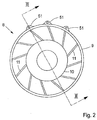
- Fig. 2 shows schematically the turbine rear frame 8 in a view indicated by the line II-II in fig. 1 .
- the turbine rear frame 8 comprises an outer casing 9, which has an annular shape, but of course alternative shapes can be allowed, for example polygonal.
- the outer casing 9 is connected to a central hub 10 via a plurality of struts 11.
- On an upper external portion of the outer casing, three mounting elements 51, in the form of lugs 51, are fixedly connected the outer casing 9, and are adapted to form parts of the rear mounting assembly 5 in that the suspension links (not shown) are to be connected at their lower ends to the lugs 51, by means of respective pins or bolts through cylindrical holes in the respective lugs 51.
- mounting elements can be provided at any suitable location, for example laterally or in a lower region of the engine.
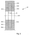
- Fig. 3 shows schematically a view of one of the lugs 51 located on the outer casing 9, and sectioned along the line III-III in fig. 2 .
- the central axis of the hole for mounting the lug to the suspension link is indicated with a broken line 511.
- the lug 51 comprises a reduced stiffness element 512, surrounding the hole 511 and extending in parallel to a central axis of the hole 511, as indicated by the double arrow A in fig 3 , throughout a central portion of the lug 51.
- Two collapsible elements 513 surround the hole 511 and extend on respective sides of the reduced stiffness element 512 as seen in the direction of a central axis of the hole 511.
- a solid framing portion 514 Surrounding the collapsible elements 513 and the reduced stiffness element 512 is a solid framing portion 514, integrally formed with the outer casing 9.
- the solid framing portion 514 can be fastened to the outer casing 9 in a suitable manner, for example by bolting.
- two solid framing portions 514 can be provided integrally formed with or fastened to the outer casing 9, and surrounding only a respective of the collapsible elements 513.
- the collapsible elements 513 are preferably made of a solid material, and are adapted to provide a first load path for transferring loads from the engine 1 to the airframe 2 during normal operational conditions.
- the collapsible elements are designed to carry loads up to a threshold load, being considerably lower than an ultimate load, which takes extreme conditions, such as those occurring during a "blade off" situation (briefly discussed above), under consideration.
- the mounting element 51 according to the invention reduces reactive forces during such extreme conditions. Therefore, the dimensions of large portions of, or the entire engine structure can be reduced, whereby the weight carried by the aircraft is reduced considerably.
- the reduced stiffness element 512 is preferably made of a material which has a modulus of elasticity which is lower than the modulus of elasticity of the material of the collapsible elements 513.
- a rubber-like compound, a metal with a relatively low stiffness, or a fibre-reinforced plastic material could be used as material for the reduced stiffness element 512.
- the reduced stiffness element 512 is adapted to provide, as described below, a second load path from the engine 1 to the airframe 2 during extreme conditions, such as the blade off situation.
- the other lugs 51 ( fig. 2 ) on the outer casing 9 are arranged in a manner similar to what has been described with reference to fig. 3 .
- the forward mounting assembly 4 ( fig. 1 ) can comprise lugs 51 arranged in such a way.
- the mounting element 51 is adapted to operate in a first mode, in which normal operational conditions occur, in which the loads do not exceed the threshold load, and in which the first load path between the engine 1 and the airframe 2 is provided by the collapsible elements 513.
- a first mode in which normal operational conditions occur, in which the loads do not exceed the threshold load, and in which the first load path between the engine 1 and the airframe 2 is provided by the collapsible elements 513.
- the loads will exceed the threshold load, and the collapsible elements 513 will collapse by being deformed plastically.
- a second load path between the engine 1 and the airframe 2 is provided by the respective reduced stiffness element 512, so that the mounting element 51 operates in a second mode.
- the mounting element 51 can also be provided according to the second aspect of the invention, where it can present an energy absorbing element 512 surrounding the hole, and being adapted to provide a load path in the second mode.
- This energy absorbing element 512 may be arranged in the same manner as the reduced stiffness element 512 described above, and can present a high damper constant to absorb energy in the second mode.
- the respective lug could comprise a collapsible element, extending throughout a central portion of the lug as seen in the direction of a central axis of the hole, and two reduced stiffness elements could extend on respective sides of the collapsible element as seen in the direction of a central axis of the hole.
- the reduced stiffness element(s) could be provided in the vicinity of the (respective) collapsible element.
- Fig. 4 shows schematically a view of one of the lugs 51 located on the outer casing 9, and sectioned along the line III-III in fig. 2 , according to an alternative embodiment of the invention.
- the lug 51 comprises a collapsible element 513, surrounding the hole 511 and extending throughout a central portion of the lug 51 as seen in the direction of a central axis of the hole 511, and is delimited by a sleeve 515 on either side.
- a bushing 516 is provided and adapted to receive a pin or similar for connecting the lug 51 to a suspension link.
- Surrounding the collapsible element 513 is a solid framing portion 514.
- the collapsible element 513 is preferably made of a solid, brittle material, for example a ceramic material. As in the embodiment described above, the collapsible element 513 is adapted to provide a load path for transferring loads from the engine 1 to the airframe 2 during normal operational conditions, without being permanently deformed or breaking.
- the mounting element 51 is adapted to operate in a first mode, in which normal operational conditions occur, and in which the loads do not exceed a threshold load. Should the unlikely situation of a blade off event, or some other predefined ultimate load condition, occur, the loads will exceed the threshold load, and the collapsible element 513 will collapse by breaking and at least partly disintegrating. Thereupon, the disintegrated portion of the collapsible element 513 will provide a load path between the engine 1 and the airframe 2, so that the mounting element 51 operates in a second mode.
- the disintegrated portion of the collapsible element 513 taking a form similar to sand, will in the second mode provide a stiffness of the mounting element 51 which is considerably lower than in the first mode. As in the embodiment described above, this will considerably reduce the reactive forces in the suspension link(s), as well as in portions of, or in the entire engine structure.
- the energy absorption capacity of the collapsible element 513 can be higher in the second mode than in the first mode.
- the other lugs 51 ( fig. 2 ) on the outer casing 9 are arranged in a manner similar to what has been described with reference to fig. 4 .
- the forward mounting assembly 4 ( fig. 1 ) can comprise lugs 51 arranged in such a way.
- the mounting element 51 could incorporate a combination of resilient elements as exemplified in fig. 3 , and collapsible elements as exemplified in fig. 4 .
- the mounting element 51 is provided between the gas turbine engine 1 and the airframe 2. This means that the mounting element 51 according to any embodiment is located so as to provide a load path between the gas turbine engine 1 and the airframe 2.
- the mounting element 51 described above with reference to fig. 3 and fig. 4 is fixedly connected to the engine 1. It should be noted that in alternative embodiments, the mounting element 51 could be differently arranged in the structure for transferring loads between the engine 1 and the airframe 2, such as at the lower end of a suspension link connected at its upper ends to the pylon 3 and at its lower ends to a traditional, solid mounting device fixedly connected to the engine 1. In further alternatives, the mounting element 51 could be located at the upper end of such a suspension link, or on the pylon 3.
- Fig. 5 shows similarly to fig. 2 the turbine rear frame 8 of an engine.
- the rear mounting assembly 5 comprises mounting elements 51, in this case two, fixedly connected to the turbine rear frame 8. These mounting elements can be arranged according to any embodiment presented above. Between the mounting elements 51 an auxiliary load transferring element 51' is provided.
- the auxiliary load transferring element 51' does not in this embodiment comprise any collapsible element. Instead it presents a hole which is elongated in the load transfer direction, i.e. vertically in fig. 5 . Thereby, it is adapted to not transfer any loads in the first mode of the mounting elements 51, i.e. during normal operation.
Landscapes
- Engineering & Computer Science (AREA)
- Aviation & Aerospace Engineering (AREA)
- Mechanical Engineering (AREA)
- General Engineering & Computer Science (AREA)
- Turbine Rotor Nozzle Sealing (AREA)
- Tires In General (AREA)
Description
- The present invention relates to a mounting element for transferring loads between a gas turbine engine and an airframe, the mounting element presenting a cylindrical hole for receiving a fastening element, such as a pin or a bolt. The invention also relates to a structure comprising such a mounting element, as well as an aircraft comprising such a mounting element.
- Aircraft gas turbine engines are attached to an associated part of the airframe by engine mounts, which transmit loads such as engine torque and thrust to the airframe. Traditionally, such engine mounts and other structural components are designed considering ultimate loads, which could be dependent on extraordinary operational conditions, such as in a "blade off" situation. The latter refers to the extremely unusual event where the fan, the compressor or the turbine in the engine during rotation sheds one or more blades, resulting in large oscillating loads on the structural components.
- A number of solutions for engine mounts have been suggested taking ultimate loads into consideration. One obvious solution is to provide the structure for the engine, including the engine mounts, as elements sized of the worst case, e.g. blade off, scenario. However, this means designing the engine structure for a very unusual case, but not optimized for normal operational conditions. In the latter, thermal loads are important contributors to stresses. The solid structure designed for the worst case will present relatively large dimensions, which will increase not only the mechanical stiffness and strength, but also thermal gradients, leading to increased stresses during normal operational conditions. In turn, this will reduce the low cycle fatigue (LFC) life of the structure. Particularly, such designs might present cracks before the desired life has been reached, resulting in costly weld repairs or replacement. Also, such a structure sized of the worst case will result in extra weight carried in the air for an unlikely event. The patent application publication
US2006/001209 IA1 -
US 4,289,060 discloses a mounting element which has a first mode and a second mode for transferring loads between components, in which the second mode loads are transferred rigidly and inflexibly between the structures. - It is an object of the invention to increase the payload capacity of an aircraft powered by one or more gas turbine engines.
- Another object of the invention is to increase the life of structural components related to gas turbine engines.
- A further object of the invention is to reduce maintenance of structural components related to gas turbine engines.
- These objects are reached by a first aspect of the invention presenting a mounting element according to claim 1.
- Surrounding the hole, and being adapted two operate in a first mode, and to operate, upon a collapse of the collapsible element, in a second mode, in which the stiffness of the mounting element is lower than in the first mode, such that reactive forces in the gas turbine engine are reduced in the second mode.
- The hole for receiving the fastening element is preferably oriented such that the mounting element is adapted to carry loads, at least in the second mode, substantially perpendicularly to the axis of the hole.
- As exemplified below, the collapsible element can be adapted to collapse by breaking and/or by plastic deformation, or by any other kind of process, eliminating or changing the load carrying capacity of the collapsible element. As also exemplified below, the mounting element can comprise one or a plurality of collapsible elements.
- The reduced stiffness of the mounting element in the second mode leads to a reduced spring coefficient of the mounting element during extreme conditions, such as in a blade off situation with rotating loads, so as to considerably reduce the reactive forces in the structure in the engine and in bearings and rotating parts of the engine. Also, the loads transferred to the airframe will be considerably lower than in the case of solid engine mounts.
- The invention allows for the collapsible element to be designed to carry loads in an un-collapsed state only up to a threshold load, being considerably lower than loads in a blade off situation. The reduced reactive forces in the second mode, obtained by the reduced stiffness of the mounting element, allows for large portions of, or the entire engine structure to be designed with considerable smaller dimensions, which in turn decreases the weight of an aircraft on which the engine is provided, and this will allow the payload capacity of the aircraft to be increased.
- The dimensions can also be kept small, and the weight can be kept low, since the collapsible element surrounds the hole. More specifically, the collapsible element surrounding the hole provides for a very compact arrangement, which is specifically advantageous in aircraft gas turbine engine mount applications, where the available space is often very limited.
- Also, the reduced dimensions of the engine structure results in less material needed for its manufacture, which reduces costs in connection thereto.
- In addition, the reduced dimensions of portions of, or the entire engine structure will reduce thermal gradients, and this in combination with the reduced mechanical stiffness will reduce stresses during normal operational conditions. In turn, this will increase the low cycle fatigue (LCF) life of portions of, or the entire engine structure. For example, it will be possible to avoid cracks before the desired life has been reached. As a result, maintenance with weld repairs or replacement can be reduced, reducing the costs thereof.
- Further, the collapsible element surrounding the hole makes it possible for the collapsible element to collapse as a result of any load which is perpendicular to the axis of the hole. Thereby, a large degree of independence of the load direction is achieved.
- Preferably, a solid portion surrounds the collapsible element. Thereby, a further backup structure is provided in the mounting element in the case of a further failure in the second mode. Such a solid portion can advantageously be designed according to general structural dimensioning principles given for aircraft gas turbine engine mounting elements.
- Preferably, the mounting element comprises a reduced stiffness element surrounding the hole, and being adapted to provide a load path in the second mode. Of course, as exemplified below, the mounting element can comprise one or a plurality of reduced stiffness elements.
- Thereby, the mounting element can be adapted so as to provide in the first mode a first load path in the mounting element via the collapsible element, and to provide, upon the collapse of the collapsible element, a second load path in the mounting element via the reduced stiffness element. It should be noted that where such a new load path is provided in the second mode, it is provided locally within the mounting element.
- The reduced stiffness element surrounding the hole contributes to the advantageously compact arrangement of the invention. Also, the reduced stiffness element surrounding the hole makes it possible for it to carry any load which is perpendicular to the axis of the hole. Thereby, a large degree of independence of the load direction is achieved.
- The reduced stiffness element could be provided adjacent to or in the vicinity of the collapsible element.
- Preferably, a solid portion surrounds the collapsible element and the reduced stiffness element. Similarly to what was mentioned above, this will provide a further backup structure in the mounting element in the case of a further failure, for example of the reduced stiffness element, in the second mode.
- In preferred embodiments, the reduced stiffness element(s) provides a lower stiffness, i.e. a greater resiliency, than the collapsible element(s) by suitable choices of dimensions and/or material for the elements. For example, the reduced stiffness element(s) can be made in a material that has a lower stiffness, i.e. a greater resiliency, than that of the collapsible element(s), such as in a metal with a lower stiffness, a fibre-reinforced plastic material or a rubber-like compound.
- In alternative embodiments, exemplified below with reference to
fig. 4 , the collapsible element can provide a load path in the second mode, the stiffness of the collapsible element being lower in the second mode than in the first mode. Thereby, the collapsible element can be adapted to at least partially disintegrate. In such embodiments, preferably, the collapsible element comprises a brittle material. - The objects are also reached by a second aspect of the invention presenting a mounting element for transferring loads between a gas turbine engine and an airframe, the mounting element presenting a cylindrical hole for receiving a fastening element, such as a pin or a bolt, the mounting element comprising a collapsible element surrounding the hole, and being adapted to operate in a first mode, and to operate, upon a collapse of the collapsible element, in a second mode, in which the energy absorption capacity of the mounting element is higher than in the first mode, such that the loads in the airframe are reduced in the second mode.
- The increased energy absorption capacity in the second mode will allow for energy from the engine, for example in a blade-off situation, to be absorbed by the mounting element, for example by converting the load energy to heat, thus preventing the energy absorbed to reach the airframe. This means that the loads will be reduced in structure between the mounting element and the airframe, as well as in the airframe, which, similarly to the first aspect of the invention will allow the structure to be designed with smaller dimensions, reducing the weight of the aircraft. Further, similarly to the case of reduced stiffness, the increased energy absorption of the mounting element in the second mode will considerably reduce the reactive forces in the structure for transferring loads between the engine and the airframe, as well as in the structure in the engine and in bearings and rotating parts of the engine, and this allows for the said load transferring structure and large portions of, or the entire engine structure to be designed with considerable smaller dimensions, which in turn decreases the weight of the aircraft. Also, as in the first aspect of the invention, the collapsible element surrounding the hole provides a very compact arrangement, and makes it possible for this element to collapse as a result of any load which is perpendicular to the axis of the hole. Thus, the first and second aspects of the invention provide alternative solutions to these particular problems. Nevertheless, features of the first and second aspects of the invention can be combined so that in addition to presenting an increased energy absorption capacity in the second mode, the mounting element can also be adapted to present a lower stiffness in the second mode.
- Similarly to embodiments of the first aspect of the invention, in embodiments where the mounting element is adapted to present an increased energy absorption capacity in the second mode, a solid portion can surround the collapsible element.
- In some embodiments the mounting element can comprise an energy absorbing element surrounding the hole, and being adapted to provide a load path in the second mode. The energy absorbing element can for example be an elastomeric damper presenting a high damper constant, i.e. considerably higher than that of the mounting element in the first mode. Thereby it will be adapted to absorb energy from the engine, thus preventing the energy absorbed to reach the airframe, and thus reducing the reactive forces in the structure for transferring loads between the engine and the airframe, and in the engine structure. For example, the energy absorbing element(s) can be made in a material that has a higher energy absorption capacity, than that of the collapsible element(s), such as in a fibre-reinforced plastic material or a rubber-like compound. As a matter of fact many materials provide features of both the first and the second aspect of the invention in that they provide both reduced stiffness and increased energy absorption in the second mode. Thus, in embodiments where the mounting element is adapted to present an increased energy absorption capacity as well as a lower stiffness in the second mode, the energy absorbing element can be identical to the reduced stiffness element described above.
- The energy absorbing element is advantageously provided adjacent to or in the vicinity of the collapsible element. Preferably, a solid portion surrounds the collapsible element and the energy absorbing element.
- As an alternative to providing an energy absorbing element, the collapsible element can provide a load path in the second mode, the energy absorption capacity of the collapsible element being higher in the second mode than in the first mode. Thereby, the collapsible element can be adapted to at least partially disintegrate, and specifically, the collapsible element can comprise a brittle material, which presents an increased energy absorption capacity when disintegrated.
- A third aspect of the invention provides a structure for transferring loads between a gas turbine engine and an airframe, the structure comprising a mounting element according to any one of the claims 1-12, the structure further comprising an auxiliary load transferring element adapted to provide in the second mode a further load path for transferring loads between the gas turbine engine and the airframe. The auxiliary load transferring element can for example be similar to what in the art is referred to as a fail-safe engine mount lug, which is provided in traditional structures as a back-up engine mount unit for the case of failure of another engine mount lug. However, according to the third aspect of the invention, where any of the mounting elements operate in the second mode, the auxiliary load transferring element provides in addition to the mounting element a further load path for transferring loads between the gas turbine engine and the airframe. This will reduce the load, not only on the mounting element(s), but also portions of the engine structure, such as struts between outer casings and hubs, thereby making it possible to decrease the dimensions and the weight of such structure.
- The objects above are also reached with an aircraft according to claim 14.
- Below, the invention will be described in detail with reference to the drawings, in which
-
fig. 1 is a schematic partly sectioned view of a gas turbine engine mounted on a wing of an aircraft, -
fig. 2 shows schematically a part of the gas turbine engine in a view indicated by the line II-II infig. 1 , -
fig. 3 shows schematically a view of a mounting element of the part infig. 2 , sectioned along the line III-III infig. 2 , -
fig. 4 shows schematically a view of a mounting element of the part infig. 2 , sectioned along the line III-III infig. 2 , according to an alternative embodiment of the invention, and -
fig. 5 shows schematically a part of a gas turbine engine in a view corresponding to the one infig. 2 with an arrangement according to a third aspect of the invention. -
Fig. 1 shows schematically a partly sectioned view of a gas turbine engine 1 mounted on anairframe 2 of an aircraft, via apylon 3, theairframe 2 being represented infig. 1 by a portion of a wing. Of course, the invention is equally applicable to other arrangements of the engine in relation to the airframe, for example where the engine is mounted externally or internally of an aircraft fuselage, or on a vertical tail. - A structure for transferring loads between the engine 1 and the
airframe 2 comprises a forward and arear mounting assembly pylon 3, and also thrust bars 6, (one of which is shown infig. 1 ), by means of which a further connection between the engine 1 and thepylon 3 is provided. Further load transferring structure components, such as torsion carrying engine mounts, can be provided between the engine 1 and theairframe 2, but they are not described further here. The forward mountingassembly 4 comprises suspension links (not shown in detail) connected at their upper ends to thepylon 3 and at their lower ends to afan casing 7 of the engine 1. Therear mounting assembly 5 comprises a fastening device (not shown) connected to thepylon 3, suspension links (not shown in detail) connected at their upper ends to the fastening device and at their lower ends to mountingelements 51, described further below with reference tofig. 3 and4 and fixedly connected to a turbinerear frame 8, located behind the turbine of the engine 1. - It should be noted that alternative arrangements for the engine mounting are of course possible. For example, the
rear mounting assembly 5 could comprise suspension links connected to a frame located between a high pressure turbine and a low pressure turbine of the engine 1. - The
structure airframe 2 comprises the mountingelements 51 described below with reference tofig. 3 and4 . -
Fig. 2 shows schematically the turbinerear frame 8 in a view indicated by the line II-II infig. 1 . The turbinerear frame 8 comprises anouter casing 9, which has an annular shape, but of course alternative shapes can be allowed, for example polygonal. Theouter casing 9 is connected to acentral hub 10 via a plurality ofstruts 11. On an upper external portion of the outer casing, three mountingelements 51, in the form oflugs 51, are fixedly connected theouter casing 9, and are adapted to form parts of the rear mountingassembly 5 in that the suspension links (not shown) are to be connected at their lower ends to thelugs 51, by means of respective pins or bolts through cylindrical holes in therespective lugs 51. It should be noted that in alternative embodiments, for example in connection to engines carried on or inside the fuselage of an aircraft, mounting elements can be provided at any suitable location, for example laterally or in a lower region of the engine. -
Fig. 3 shows schematically a view of one of thelugs 51 located on theouter casing 9, and sectioned along the line III-III infig. 2 . Infig. 3 , the central axis of the hole for mounting the lug to the suspension link is indicated with abroken line 511. Thelug 51 comprises a reducedstiffness element 512, surrounding thehole 511 and extending in parallel to a central axis of thehole 511, as indicated by the double arrow A infig 3 , throughout a central portion of thelug 51. Twocollapsible elements 513 surround thehole 511 and extend on respective sides of the reducedstiffness element 512 as seen in the direction of a central axis of thehole 511. Surrounding thecollapsible elements 513 and the reducedstiffness element 512 is asolid framing portion 514, integrally formed with theouter casing 9. As an alternative, thesolid framing portion 514 can be fastened to theouter casing 9 in a suitable manner, for example by bolting. As a further alternative, twosolid framing portions 514 can be provided integrally formed with or fastened to theouter casing 9, and surrounding only a respective of thecollapsible elements 513. - The
collapsible elements 513 are preferably made of a solid material, and are adapted to provide a first load path for transferring loads from the engine 1 to theairframe 2 during normal operational conditions. Thus, the collapsible elements are designed to carry loads up to a threshold load, being considerably lower than an ultimate load, which takes extreme conditions, such as those occurring during a "blade off" situation (briefly discussed above), under consideration. As mentioned, the mountingelement 51 according to the invention reduces reactive forces during such extreme conditions. Therefore, the dimensions of large portions of, or the entire engine structure can be reduced, whereby the weight carried by the aircraft is reduced considerably. - The reduced
stiffness element 512 is preferably made of a material which has a modulus of elasticity which is lower than the modulus of elasticity of the material of thecollapsible elements 513. For example, a rubber-like compound, a metal with a relatively low stiffness, or a fibre-reinforced plastic material could be used as material for the reducedstiffness element 512. The reducedstiffness element 512 is adapted to provide, as described below, a second load path from the engine 1 to theairframe 2 during extreme conditions, such as the blade off situation. - Preferably, the other lugs 51 (
fig. 2 ) on theouter casing 9 are arranged in a manner similar to what has been described with reference tofig. 3 . Also, the forward mounting assembly 4 (fig. 1 ) can compriselugs 51 arranged in such a way. - By means of the
collapsible elements 513, the mountingelement 51 is adapted to operate in a first mode, in which normal operational conditions occur, in which the loads do not exceed the threshold load, and in which the first load path between the engine 1 and theairframe 2 is provided by thecollapsible elements 513. Should the unlikely situation of a blade off event, or some other predefined ultimate load condition, occur, the loads will exceed the threshold load, and thecollapsible elements 513 will collapse by being deformed plastically. Thereupon, in eachlug 51 arranged as shown infig. 3 , a second load path between the engine 1 and theairframe 2 is provided by the respective reducedstiffness element 512, so that the mountingelement 51 operates in a second mode. - Due to the resiliency of the reduced stiffness element (s) 512, in the second mode, the stiffness of the mounting
element 51 is considerably lower than in the first mode. This will considerably reduce the reactive forces in the suspension link(s), and therefore loads transferred to theairframe 2 will be considerably lower than in the case of a solid engine mount. Also, the reduced stiffness of the mountingelement 51 will considerably reduce the reactive forces within the engine structure as well. - It should be noted that the mounting
element 51 can also be provided according to the second aspect of the invention, where it can present anenergy absorbing element 512 surrounding the hole, and being adapted to provide a load path in the second mode. Thisenergy absorbing element 512 may be arranged in the same manner as the reducedstiffness element 512 described above, and can present a high damper constant to absorb energy in the second mode. - Alternatives to the embodiment described above are possible. For example, the respective lug could comprise a collapsible element, extending throughout a central portion of the lug as seen in the direction of a central axis of the hole, and two reduced stiffness elements could extend on respective sides of the collapsible element as seen in the direction of a central axis of the hole.
- As a further alternative, instead of the reduced stiffness element(s) being provided adjacent to the (respective) collapsible elements, the reduced stiffness element(s) could be provided in the vicinity of the (respective) collapsible element.
-
Fig. 4 shows schematically a view of one of thelugs 51 located on theouter casing 9, and sectioned along the line III-III infig. 2 , according to an alternative embodiment of the invention. Thelug 51 comprises acollapsible element 513, surrounding thehole 511 and extending throughout a central portion of thelug 51 as seen in the direction of a central axis of thehole 511, and is delimited by asleeve 515 on either side. Radially inwards of the collapsible element, abushing 516 is provided and adapted to receive a pin or similar for connecting thelug 51 to a suspension link. Surrounding thecollapsible element 513 is asolid framing portion 514. - The
collapsible element 513 is preferably made of a solid, brittle material, for example a ceramic material. As in the embodiment described above, thecollapsible element 513 is adapted to provide a load path for transferring loads from the engine 1 to theairframe 2 during normal operational conditions, without being permanently deformed or breaking. - By means of the
collapsible element 513, the mountingelement 51 is adapted to operate in a first mode, in which normal operational conditions occur, and in which the loads do not exceed a threshold load. Should the unlikely situation of a blade off event, or some other predefined ultimate load condition, occur, the loads will exceed the threshold load, and thecollapsible element 513 will collapse by breaking and at least partly disintegrating. Thereupon, the disintegrated portion of thecollapsible element 513 will provide a load path between the engine 1 and theairframe 2, so that the mountingelement 51 operates in a second mode. The disintegrated portion of thecollapsible element 513, taking a form similar to sand, will in the second mode provide a stiffness of the mountingelement 51 which is considerably lower than in the first mode. As in the embodiment described above, this will considerably reduce the reactive forces in the suspension link(s), as well as in portions of, or in the entire engine structure. - In addition to providing a decreased stiffness in the second mode, the energy absorption capacity of the
collapsible element 513 can be higher in the second mode than in the first mode. - Preferably, the other lugs 51 (
fig. 2 ) on theouter casing 9 are arranged in a manner similar to what has been described with reference tofig. 4 . Also, the forward mounting assembly 4 (fig. 1 ) can compriselugs 51 arranged in such a way. - In alternative embodiments, the mounting
element 51 could incorporate a combination of resilient elements as exemplified infig. 3 , and collapsible elements as exemplified infig. 4 . - In use, the mounting
element 51 according to any embodiment is provided between the gas turbine engine 1 and theairframe 2. This means that the mountingelement 51 according to any embodiment is located so as to provide a load path between the gas turbine engine 1 and theairframe 2. The mountingelement 51 described above with reference tofig. 3 andfig. 4 is fixedly connected to the engine 1. It should be noted that in alternative embodiments, the mountingelement 51 could be differently arranged in the structure for transferring loads between the engine 1 and theairframe 2, such as at the lower end of a suspension link connected at its upper ends to thepylon 3 and at its lower ends to a traditional, solid mounting device fixedly connected to the engine 1. In further alternatives, the mountingelement 51 could be located at the upper end of such a suspension link, or on thepylon 3. - Referring to
fig. 5 , an embodiment of a third aspect of the invention will be presented.Fig. 5 shows similarly tofig. 2 the turbinerear frame 8 of an engine. As in the embodiments described above, therear mounting assembly 5 comprises mountingelements 51, in this case two, fixedly connected to the turbinerear frame 8. These mounting elements can be arranged according to any embodiment presented above. Between the mountingelements 51 an auxiliary load transferring element 51' is provided. The auxiliary load transferring element 51' does not in this embodiment comprise any collapsible element. Instead it presents a hole which is elongated in the load transfer direction, i.e. vertically infig. 5 . Thereby, it is adapted to not transfer any loads in the first mode of the mountingelements 51, i.e. during normal operation. However, it adapted to provide in the second mode of any of the mountingelements 51, where much larger movements of the engine in relation to the airframe usually occur, a further load path for transferring loads between the engine and the airframe, thereby reducing the load on the mountingelements 51.
Claims (14)
- A mounting element (51) for transferring loads between a gas turbine engine (1) and an airframe (2), the mounting element (51) presenting a cylindrical hole (511) for receiving a fastening element, such as a pin or a bolt, characterized in that it comprises a collapsible element (513) surrounding the hole (511), and in that it is adapted to operate in a first mode, and to operate, upon a collapse of the collapsible element (513), in a second mode, in which the stiffness of the mounting element (51) is lower than in the first mode, such that reactive forces in the gas turbine engine are reduced in the second mode.
- A mounting element according to claim 1, comprising a solid portion (514) surrounding the collapsible element (513).
- A mounting element according to any one of the claims 1-2, comprising a reduced stiffness element (512) surrounding the hole (511), and being adapted to provide a load path in the second mode.
- A mounting element according to claim 3, wherein the reduced stiffness element (512) is provided adjacent to or in the vicinity of the collapsible element (513).
- A mounting element according to any one of the claims 3-4, comprising a solid portion (514) surrounding the collapsible element (513) and the reduced stiffness element (512).
- A mounting element according to any of the preceding claims, wherein the collapsible element (513) provides a load path in the second mode, the stiffness of the collapsible element (513) being lower in the second mode than in the first mode.
- A mounting element according to claim 6, wherein the collapsible element (513) is adapted to at least partially disintegrate.
- A mounting element according to claim 7, wherein the collapsible element (513) comprises a brittle material.
- A mounting element (51) for transferring loads between a gas turbine engine (1) and an airframe (2), the mounting element (51) presenting a cylindrical hole (511) for receiving a fastening element, such as a pin or a bolt, characterized in that it comprises a collapsible element (513) surrounding the hole (511), and in that it is adapted to operate in a first mode, and to operate, upon a collapse of the collapsible element (513), in a second mode, in which the energy absorption capacity of the mounting element (51) is higher than in the first mode, such that the loads in the airframe are reduced in the second mode.
- A mounting element according to claim 9, comprising a solid portion (514) surrounding the collapsible element (513).
- A mounting element according to any one of the claims 9-10, comprising an energy absorbing element (512) surrounding the hole (511), and being adapted to provide a load path in the second mode.
- A mounting element according to any one of the claims 9-11, wherein the collapsible element (513) provides a load path in the second mode, the energy absorption capacity of the collapsible element (513) being higher in the second mode than in the first mode.
- A structure (4, 5, 6) for transferring loads between a gas turbine engine (1) and an airframe (2), the structure comprising a mounting element according to any one of the claims 1-12, the structure further comprising an auxiliary load transferring element (51') adapted to provide in the second mode a further load path for transferring loads between the gas turbine engine (1) and the airframe (2).
- An aircraft comprising a mounting element according to any of the claims 1-12.
Applications Claiming Priority (2)
| Application Number | Priority Date | Filing Date | Title |
|---|---|---|---|
| PCT/SE2007/000561 WO2008150202A1 (en) | 2007-06-08 | 2007-06-08 | A structure for transferring loads at a gas turbine engine, and an engine and an aircraft with such a structure |
| PCT/SE2008/000384 WO2008150213A1 (en) | 2007-06-08 | 2008-06-09 | A mounting element for a gas turbine engine, and a structure and an aircraft with such a mounting element |
Publications (3)
| Publication Number | Publication Date |
|---|---|
| EP2155555A1 EP2155555A1 (en) | 2010-02-24 |
| EP2155555A4 EP2155555A4 (en) | 2013-06-26 |
| EP2155555B1 true EP2155555B1 (en) | 2016-08-10 |
Family
ID=40093906
Family Applications (1)
| Application Number | Title | Priority Date | Filing Date |
|---|---|---|---|
| EP08767057.6A Not-in-force EP2155555B1 (en) | 2007-06-08 | 2008-06-09 | A mounting element for a gas turbine engine, and a structure and an aircraft with such a mounting element |
Country Status (3)
| Country | Link |
|---|---|
| US (1) | US20100163671A1 (en) |
| EP (1) | EP2155555B1 (en) |
| WO (2) | WO2008150202A1 (en) |
Families Citing this family (7)
| Publication number | Priority date | Publication date | Assignee | Title |
|---|---|---|---|---|
| FR2928180B1 (en) * | 2008-02-28 | 2010-04-02 | Airbus France | AIRCRAFT ENGINE ASSEMBLY COMPRISING AN ANNULAR EFFORTS TRANSFER STRUCTURE SURROUNDING THE CENTRAL HOUSING OF A TURBOJET ENGINE. |
| US8087874B2 (en) * | 2009-02-27 | 2012-01-03 | Honeywell International Inc. | Retention structures and exit guide vane assemblies |
| FR2963390B1 (en) | 2010-07-30 | 2012-08-31 | Snecma | IMPROVED SIDE TURBOREACTOR TO LIMIT ITS DEFORMATIONS |
| US8979020B2 (en) | 2013-06-07 | 2015-03-17 | Pratt & Whitney Canada Corp. | Mounting system for mounting engine nacelle components and associated method |
| US10266273B2 (en) | 2013-07-26 | 2019-04-23 | Mra Systems, Llc | Aircraft engine pylon |
| FR3016863B1 (en) * | 2014-01-29 | 2017-05-26 | Snecma | NACELLE FOR AIRCRAFT TURBO AIRCRAFT |
| US11066178B2 (en) | 2015-09-02 | 2021-07-20 | Raytheon Technologies Corporation | Link for aircraft component mounting |
Family Cites Families (50)
| Publication number | Priority date | Publication date | Assignee | Title |
|---|---|---|---|---|
| US2257538A (en) * | 1938-04-26 | 1941-09-30 | Schlueter Ernest | Expanded fastening device |
| US2324142A (en) * | 1941-04-03 | 1943-07-13 | Rolyan Corp | Rivet and method of making same |
| US2585285A (en) * | 1948-08-18 | 1952-02-12 | Goodrich Co B F | Separable fastening apparatus for structure wall attachments |
| US2761638A (en) * | 1953-11-17 | 1956-09-04 | Gordon L Getline | Vibration-isolating power plant mounting system |
| US2834998A (en) * | 1954-01-25 | 1958-05-20 | Douglas Aircraft Co Inc | Means for mounting a frangible expanse to a vibratile support |
| US3120873A (en) * | 1961-02-09 | 1964-02-11 | Martin L Bledsoe | Plow mounting connection |
| US3493082A (en) * | 1967-12-18 | 1970-02-03 | Mc Donnell Douglas Corp | Crushable energy absorber |
| US4193741A (en) * | 1976-12-07 | 1980-03-18 | Rolls-Royce Limited | Gas turbine engines |
| US4289060A (en) * | 1977-10-03 | 1981-09-15 | Hooker Chemicals & Plastics Corp. | Device and assembly for mounting parts |
| US4289061A (en) * | 1977-10-03 | 1981-09-15 | Hooker Chemicals & Plastics Corp. | Device and assembly for mounting parts |
| US4834569A (en) * | 1987-05-13 | 1989-05-30 | The Boeing Company | Thermal expansion compensating joint assembly |
| DE4010476A1 (en) * | 1990-03-31 | 1991-10-02 | Ischebeck Friedrich Gmbh | ON ANCHORS, ESPECIALLY INJECTION ANCHORS FOR MINING OR THE LIKE CONTROL NUT LOCKING WITH LOADING DISPLAY DEVICE |
| US5351930A (en) * | 1992-08-11 | 1994-10-04 | Lord Corporation | Mounting for engines and the like |
| US5603592A (en) * | 1994-10-03 | 1997-02-18 | Huck International, Inc. | High strength blind bolt with uniform high clamp over an extended grip range |
| US5704572A (en) * | 1995-10-06 | 1998-01-06 | Illinois Tool Works Inc. | Method and apparatus for fastening |
| US6212974B1 (en) * | 1998-12-17 | 2001-04-10 | United Technologies Corporation | Variable stiffness positioning link for a gearbox |
| US6331078B1 (en) * | 1998-12-23 | 2001-12-18 | United Technologies Corporation | Turbine engine bearing |
| US6871820B2 (en) * | 1999-06-30 | 2005-03-29 | Mark Conrad Wilksch | Aircraft engine mounting |
| GB2360069B (en) * | 2000-03-11 | 2003-11-26 | Rolls Royce Plc | Ducted fan gas turbine engine |
| US6447248B1 (en) * | 2000-10-20 | 2002-09-10 | General Electric Company | Bearing support fuse |
| CN1229580C (en) * | 2000-12-18 | 2005-11-30 | 新日本制铁株式会社 | Strong bolt connection structure and nut fixing method thereof, and torsional shear type strong bolt and connection method using same |
| FR2820402B1 (en) * | 2001-02-08 | 2003-05-02 | Eads Airbus Sa | DEVICE FOR HANGING AN ENGINE ON AN AIRCRAFT |
| FR2828167B1 (en) * | 2001-07-31 | 2003-11-21 | Airbus France | DEVICE FOR HANGING AN ENGINE ON AN AIRCRAFT |
| US6582172B2 (en) * | 2001-08-29 | 2003-06-24 | The United States Of America As Represented By The Secretary Of The Navy | Isolated mechanical fastening system |
| US6669393B2 (en) * | 2001-10-10 | 2003-12-30 | General Electric Co. | Connector assembly for gas turbine engines |
| FR2836672B1 (en) * | 2002-03-04 | 2004-06-04 | Airbus France | MATCH FOR HANGING AN ENGINE UNDER AN AIRCRAFT |
| US6702232B2 (en) * | 2002-04-05 | 2004-03-09 | The Boeing Company | Jam resistant and intruder-proof flight deck door |
| US20030194287A1 (en) * | 2002-04-15 | 2003-10-16 | Hageman David C. | Clamp load indicator device for fasteners |
| DE60335589D1 (en) * | 2002-07-01 | 2011-02-17 | Barry Controls Corp | Two-tone vibration damper |
| GB2403992B (en) * | 2003-07-16 | 2006-10-11 | Newfrey Llc | Three part blind fastener |
| FR2867155B1 (en) * | 2004-03-08 | 2007-06-29 | Snecma Moteurs | SUSPENSION OF AN ENGINE TO THE STRUCTURE OF AN AIRCRAFT |
| FR2869874B1 (en) * | 2004-05-04 | 2006-06-23 | Snecma Moteurs Sa | AIRCRAFT ENGINE WITH MEANS OF SUSPENSION TO THE STRUCTURE OF AN AIRCRAFT |
| GB0413276D0 (en) * | 2004-06-14 | 2004-07-14 | Rolls Royce Plc | Load reduced engine mount |
| FR2877994B1 (en) * | 2004-11-17 | 2009-07-10 | Snecma Moteurs Sa | BEARING SUPPORT, AND AIRCRAFT ENGINE EQUIPPED WITH SUCH A BEARING SUPPORT. |
| FR2878229B1 (en) * | 2004-11-23 | 2008-04-18 | Airbus France Sas | SYSTEM FOR ATTACHING A MOTOR MAT TO THE WING OF AN AIRCRAFT |
| FR2887853B1 (en) * | 2005-06-29 | 2007-08-17 | Airbus France Sas | ENGINE ATTACHMENT FOR AN AIRCRAFT INTENDED TO BE INTERPOSED BETWEEN A MOTOR AND A COUPLING MAT |
| FR2891253B1 (en) * | 2005-09-28 | 2007-10-26 | Airbus France Sas | REAR ATTACHMENT OF A TWO-SHOWN AIRCRAFT ENGINE |
| FR2893367B1 (en) * | 2005-11-17 | 2007-12-21 | Airbus France Sas | DEVICE FOR SECURING AN INSERT IN A STRUCTURE |
| US8104736B2 (en) * | 2005-12-01 | 2012-01-31 | Hamilton Sundstrand Corporation | Gas turbine engine auxiliary component mount |
| FR2894934B1 (en) * | 2005-12-15 | 2009-11-13 | Airbus France | REAR AXLE ATTACHMENT OF AN AIRCRAFT ENGINE WITH MANILITY WAITING FOR AND SPRING FOR SUCH AN AXIS WAITING |
| GB0607991D0 (en) * | 2006-04-22 | 2006-05-31 | Rolls Royce Plc | Aeroengine mounting |
| FR2905932B1 (en) * | 2006-09-20 | 2008-12-05 | Airbus France Sa | ARRANGEMENT FOR ATTACHING DEVICE FOR ATTACHING AN AIRCRAFT ENGINE |
| JP4118314B1 (en) * | 2007-04-27 | 2008-07-16 | 株式会社椿本チエイン | Cable protection guide device |
| GB0723506D0 (en) * | 2007-12-03 | 2008-01-09 | Airbus Uk Ltd | Apparatus for indicating loading in a structure having exceeded a predetermined threshold |
| US8136766B2 (en) * | 2008-02-01 | 2012-03-20 | Insitu, Inc. | Frangible fasteners for aircraft components and associated systems and methods |
| US8192102B2 (en) * | 2008-11-26 | 2012-06-05 | The Boeing Company | Load absorption system |
| WO2011011569A1 (en) * | 2009-07-23 | 2011-01-27 | Gkn Sinter Metals, Llc | Compression limiter having retention features |
| JP5473892B2 (en) * | 2010-12-28 | 2014-04-16 | 三菱航空機株式会社 | Lightning-resistant fasteners, aircraft |
| TWI508646B (en) * | 2013-04-23 | 2015-11-11 | Hon Hai Prec Ind Co Ltd | Fixing device and plate assembly |
| US9039287B2 (en) * | 2013-09-18 | 2015-05-26 | Dana Automotive Systems Group, Inc. | Perforated collapsible spacer |
-
2007
- 2007-06-08 WO PCT/SE2007/000561 patent/WO2008150202A1/en not_active Ceased
-
2008
- 2008-06-09 US US12/600,534 patent/US20100163671A1/en not_active Abandoned
- 2008-06-09 EP EP08767057.6A patent/EP2155555B1/en not_active Not-in-force
- 2008-06-09 WO PCT/SE2008/000384 patent/WO2008150213A1/en not_active Ceased
Also Published As
| Publication number | Publication date |
|---|---|
| WO2008150202A1 (en) | 2008-12-11 |
| US20100163671A1 (en) | 2010-07-01 |
| EP2155555A4 (en) | 2013-06-26 |
| WO2008150213A1 (en) | 2008-12-11 |
| EP2155555A1 (en) | 2010-02-24 |
Similar Documents
| Publication | Publication Date | Title |
|---|---|---|
| US20100163671A1 (en) | A mounting element for a gas turbine engine, and a structure and an aircraft with such a mounting element | |
| EP0311155B1 (en) | Vibration isolating engine mount | |
| JP4498694B2 (en) | Aircraft engine mount with a single thrust link | |
| EP1561684B1 (en) | Fail-safe aircraft engine mounting system | |
| JP4990545B2 (en) | Suspension for hanging a jet engine on an aircraft strut | |
| US7677047B2 (en) | Inverted stiffened shell panel torque transmission for loaded struts and mid-turbine frames | |
| JP5642379B2 (en) | Aircraft engine mount, aircraft | |
| US11673659B2 (en) | Light-weight, elastic teeter bearing for a rotor and aircraft housing such bearing | |
| US8322652B1 (en) | Thrust mount arrangement for an aircraft engine | |
| US10836500B2 (en) | Assembly between an aircraft pylon and a turbine engine | |
| US9878800B2 (en) | Rat mounting arrangement for a soft aircraft interface | |
| US9863273B2 (en) | Isostatic suspension of a turbojet by rear double support | |
| KR101911850B1 (en) | A helicopter with a fuselage and a composite tail boom | |
| CN112049814B (en) | Fan rotor support system and bearing support device that can lose efficacy of aeroengine | |
| EP1447543B1 (en) | Gas turbine engine bearing support | |
| US9499274B2 (en) | Aircraft pylon and aircraft | |
| EP1541468B1 (en) | Aircraft turbofan engine mounting | |
| CN103080481A (en) | Hyperstatic truss comprising connecting rods | |
| EP1780125B1 (en) | Support system for auxiliary power unit | |
| EP4442969A1 (en) | Assembly for mounting an auxiliary component to an engine case of a gas turbine engine, gas turbine engine and locator for mounting an auxiliary component to an engine case of a gas turbine engine | |
| US20070056292A1 (en) | Auxiliary power unit case flange to cone bolt adapter | |
| CN111980958B (en) | Fusing system and aircraft engine | |
| US20260091878A1 (en) | Aircraft propulsion assembly comprising a supporting structure connecting an engine assembly and a primary structure of a pylon and supporting at least one accessory | |
| CN120739836A (en) | Load reducing device and open rotor engine | |
| CN119239960A (en) | Attachment of pylon to aircraft engine assembly |
Legal Events
| Date | Code | Title | Description |
|---|---|---|---|
| PUAI | Public reference made under article 153(3) epc to a published international application that has entered the european phase |
Free format text: ORIGINAL CODE: 0009012 |
|
| 17P | Request for examination filed |
Effective date: 20100108 |
|
| AK | Designated contracting states |
Kind code of ref document: A1 Designated state(s): AT BE BG CH CY CZ DE DK EE ES FI FR GB GR HR HU IE IS IT LI LT LU LV MC MT NL NO PL PT RO SE SI SK TR |
|
| AX | Request for extension of the european patent |
Extension state: AL BA MK RS |
|
| DAX | Request for extension of the european patent (deleted) | ||
| A4 | Supplementary search report drawn up and despatched |
Effective date: 20130528 |
|
| RAP1 | Party data changed (applicant data changed or rights of an application transferred) |
Owner name: GKN AEROSPACE SWEDEN AB |
|
| RIC1 | Information provided on ipc code assigned before grant |
Ipc: B64D 27/26 20060101AFI20130522BHEP Ipc: F02C 7/20 20060101ALI20130522BHEP |
|
| GRAP | Despatch of communication of intention to grant a patent |
Free format text: ORIGINAL CODE: EPIDOSNIGR1 |
|
| INTG | Intention to grant announced |
Effective date: 20151002 |
|
| INTG | Intention to grant announced |
Effective date: 20160302 |
|
| GRAS | Grant fee paid |
Free format text: ORIGINAL CODE: EPIDOSNIGR3 |
|
| GRAA | (expected) grant |
Free format text: ORIGINAL CODE: 0009210 |
|
| AK | Designated contracting states |
Kind code of ref document: B1 Designated state(s): AT BE BG CH CY CZ DE DK EE ES FI FR GB GR HR HU IE IS IT LI LT LU LV MC MT NL NO PL PT RO SE SI SK TR |
|
| REG | Reference to a national code |
Ref country code: GB Ref legal event code: FG4D |
|
| REG | Reference to a national code |
Ref country code: CH Ref legal event code: EP Ref country code: AT Ref legal event code: REF Ref document number: 818740 Country of ref document: AT Kind code of ref document: T Effective date: 20160815 |
|
| REG | Reference to a national code |
Ref country code: IE Ref legal event code: FG4D |
|
| REG | Reference to a national code |
Ref country code: DE Ref legal event code: R096 Ref document number: 602008045581 Country of ref document: DE |
|
| REG | Reference to a national code |
Ref country code: LT Ref legal event code: MG4D |
|
| REG | Reference to a national code |
Ref country code: NL Ref legal event code: MP Effective date: 20160810 |
|
| REG | Reference to a national code |
Ref country code: AT Ref legal event code: MK05 Ref document number: 818740 Country of ref document: AT Kind code of ref document: T Effective date: 20160810 |
|
| PG25 | Lapsed in a contracting state [announced via postgrant information from national office to epo] |
Ref country code: IS Free format text: LAPSE BECAUSE OF FAILURE TO SUBMIT A TRANSLATION OF THE DESCRIPTION OR TO PAY THE FEE WITHIN THE PRESCRIBED TIME-LIMIT Effective date: 20161210 Ref country code: LT Free format text: LAPSE BECAUSE OF FAILURE TO SUBMIT A TRANSLATION OF THE DESCRIPTION OR TO PAY THE FEE WITHIN THE PRESCRIBED TIME-LIMIT Effective date: 20160810 Ref country code: FI Free format text: LAPSE BECAUSE OF FAILURE TO SUBMIT A TRANSLATION OF THE DESCRIPTION OR TO PAY THE FEE WITHIN THE PRESCRIBED TIME-LIMIT Effective date: 20160810 Ref country code: NL Free format text: LAPSE BECAUSE OF FAILURE TO SUBMIT A TRANSLATION OF THE DESCRIPTION OR TO PAY THE FEE WITHIN THE PRESCRIBED TIME-LIMIT Effective date: 20160810 Ref country code: HR Free format text: LAPSE BECAUSE OF FAILURE TO SUBMIT A TRANSLATION OF THE DESCRIPTION OR TO PAY THE FEE WITHIN THE PRESCRIBED TIME-LIMIT Effective date: 20160810 Ref country code: NO Free format text: LAPSE BECAUSE OF FAILURE TO SUBMIT A TRANSLATION OF THE DESCRIPTION OR TO PAY THE FEE WITHIN THE PRESCRIBED TIME-LIMIT Effective date: 20161110 Ref country code: IT Free format text: LAPSE BECAUSE OF FAILURE TO SUBMIT A TRANSLATION OF THE DESCRIPTION OR TO PAY THE FEE WITHIN THE PRESCRIBED TIME-LIMIT Effective date: 20160810 |
|
| PG25 | Lapsed in a contracting state [announced via postgrant information from national office to epo] |
Ref country code: AT Free format text: LAPSE BECAUSE OF FAILURE TO SUBMIT A TRANSLATION OF THE DESCRIPTION OR TO PAY THE FEE WITHIN THE PRESCRIBED TIME-LIMIT Effective date: 20160810 Ref country code: PL Free format text: LAPSE BECAUSE OF FAILURE TO SUBMIT A TRANSLATION OF THE DESCRIPTION OR TO PAY THE FEE WITHIN THE PRESCRIBED TIME-LIMIT Effective date: 20160810 Ref country code: PT Free format text: LAPSE BECAUSE OF FAILURE TO SUBMIT A TRANSLATION OF THE DESCRIPTION OR TO PAY THE FEE WITHIN THE PRESCRIBED TIME-LIMIT Effective date: 20161212 Ref country code: LV Free format text: LAPSE BECAUSE OF FAILURE TO SUBMIT A TRANSLATION OF THE DESCRIPTION OR TO PAY THE FEE WITHIN THE PRESCRIBED TIME-LIMIT Effective date: 20160810 Ref country code: GR Free format text: LAPSE BECAUSE OF FAILURE TO SUBMIT A TRANSLATION OF THE DESCRIPTION OR TO PAY THE FEE WITHIN THE PRESCRIBED TIME-LIMIT Effective date: 20161111 Ref country code: ES Free format text: LAPSE BECAUSE OF FAILURE TO SUBMIT A TRANSLATION OF THE DESCRIPTION OR TO PAY THE FEE WITHIN THE PRESCRIBED TIME-LIMIT Effective date: 20160810 Ref country code: SE Free format text: LAPSE BECAUSE OF FAILURE TO SUBMIT A TRANSLATION OF THE DESCRIPTION OR TO PAY THE FEE WITHIN THE PRESCRIBED TIME-LIMIT Effective date: 20160810 |
|
| PG25 | Lapsed in a contracting state [announced via postgrant information from national office to epo] |
Ref country code: EE Free format text: LAPSE BECAUSE OF FAILURE TO SUBMIT A TRANSLATION OF THE DESCRIPTION OR TO PAY THE FEE WITHIN THE PRESCRIBED TIME-LIMIT Effective date: 20160810 Ref country code: RO Free format text: LAPSE BECAUSE OF FAILURE TO SUBMIT A TRANSLATION OF THE DESCRIPTION OR TO PAY THE FEE WITHIN THE PRESCRIBED TIME-LIMIT Effective date: 20160810 |
|
| REG | Reference to a national code |
Ref country code: FR Ref legal event code: PLFP Year of fee payment: 10 Ref country code: DE Ref legal event code: R097 Ref document number: 602008045581 Country of ref document: DE |
|
| PG25 | Lapsed in a contracting state [announced via postgrant information from national office to epo] |
Ref country code: BG Free format text: LAPSE BECAUSE OF FAILURE TO SUBMIT A TRANSLATION OF THE DESCRIPTION OR TO PAY THE FEE WITHIN THE PRESCRIBED TIME-LIMIT Effective date: 20161110 Ref country code: DK Free format text: LAPSE BECAUSE OF FAILURE TO SUBMIT A TRANSLATION OF THE DESCRIPTION OR TO PAY THE FEE WITHIN THE PRESCRIBED TIME-LIMIT Effective date: 20160810 Ref country code: SK Free format text: LAPSE BECAUSE OF FAILURE TO SUBMIT A TRANSLATION OF THE DESCRIPTION OR TO PAY THE FEE WITHIN THE PRESCRIBED TIME-LIMIT Effective date: 20160810 Ref country code: BE Free format text: LAPSE BECAUSE OF FAILURE TO SUBMIT A TRANSLATION OF THE DESCRIPTION OR TO PAY THE FEE WITHIN THE PRESCRIBED TIME-LIMIT Effective date: 20160810 Ref country code: CZ Free format text: LAPSE BECAUSE OF FAILURE TO SUBMIT A TRANSLATION OF THE DESCRIPTION OR TO PAY THE FEE WITHIN THE PRESCRIBED TIME-LIMIT Effective date: 20160810 |
|
| PLBE | No opposition filed within time limit |
Free format text: ORIGINAL CODE: 0009261 |
|
| STAA | Information on the status of an ep patent application or granted ep patent |
Free format text: STATUS: NO OPPOSITION FILED WITHIN TIME LIMIT |
|
| 26N | No opposition filed |
Effective date: 20170511 |
|
| PG25 | Lapsed in a contracting state [announced via postgrant information from national office to epo] |
Ref country code: SI Free format text: LAPSE BECAUSE OF FAILURE TO SUBMIT A TRANSLATION OF THE DESCRIPTION OR TO PAY THE FEE WITHIN THE PRESCRIBED TIME-LIMIT Effective date: 20160810 |
|
| PG25 | Lapsed in a contracting state [announced via postgrant information from national office to epo] |
Ref country code: MC Free format text: LAPSE BECAUSE OF FAILURE TO SUBMIT A TRANSLATION OF THE DESCRIPTION OR TO PAY THE FEE WITHIN THE PRESCRIBED TIME-LIMIT Effective date: 20160810 |
|
| REG | Reference to a national code |
Ref country code: CH Ref legal event code: PL |
|
| REG | Reference to a national code |
Ref country code: IE Ref legal event code: MM4A |
|
| PG25 | Lapsed in a contracting state [announced via postgrant information from national office to epo] |
Ref country code: LI Free format text: LAPSE BECAUSE OF NON-PAYMENT OF DUE FEES Effective date: 20170630 Ref country code: CH Free format text: LAPSE BECAUSE OF NON-PAYMENT OF DUE FEES Effective date: 20170630 Ref country code: IE Free format text: LAPSE BECAUSE OF NON-PAYMENT OF DUE FEES Effective date: 20170609 Ref country code: LU Free format text: LAPSE BECAUSE OF NON-PAYMENT OF DUE FEES Effective date: 20170609 |
|
| REG | Reference to a national code |
Ref country code: FR Ref legal event code: PLFP Year of fee payment: 11 |
|
| PGFP | Annual fee paid to national office [announced via postgrant information from national office to epo] |
Ref country code: DE Payment date: 20180530 Year of fee payment: 11 |
|
| PGFP | Annual fee paid to national office [announced via postgrant information from national office to epo] |
Ref country code: FR Payment date: 20180514 Year of fee payment: 11 |
|
| PG25 | Lapsed in a contracting state [announced via postgrant information from national office to epo] |
Ref country code: MT Free format text: LAPSE BECAUSE OF NON-PAYMENT OF DUE FEES Effective date: 20170609 |
|
| PGFP | Annual fee paid to national office [announced via postgrant information from national office to epo] |
Ref country code: GB Payment date: 20180403 Year of fee payment: 11 |
|
| PG25 | Lapsed in a contracting state [announced via postgrant information from national office to epo] |
Ref country code: HU Free format text: LAPSE BECAUSE OF FAILURE TO SUBMIT A TRANSLATION OF THE DESCRIPTION OR TO PAY THE FEE WITHIN THE PRESCRIBED TIME-LIMIT; INVALID AB INITIO Effective date: 20080609 |
|
| PG25 | Lapsed in a contracting state [announced via postgrant information from national office to epo] |
Ref country code: CY Free format text: LAPSE BECAUSE OF NON-PAYMENT OF DUE FEES Effective date: 20160810 |
|
| REG | Reference to a national code |
Ref country code: DE Ref legal event code: R119 Ref document number: 602008045581 Country of ref document: DE |
|
| GBPC | Gb: european patent ceased through non-payment of renewal fee |
Effective date: 20190609 |
|
| PG25 | Lapsed in a contracting state [announced via postgrant information from national office to epo] |
Ref country code: TR Free format text: LAPSE BECAUSE OF FAILURE TO SUBMIT A TRANSLATION OF THE DESCRIPTION OR TO PAY THE FEE WITHIN THE PRESCRIBED TIME-LIMIT Effective date: 20160810 |
|
| PG25 | Lapsed in a contracting state [announced via postgrant information from national office to epo] |
Ref country code: DE Free format text: LAPSE BECAUSE OF NON-PAYMENT OF DUE FEES Effective date: 20200101 Ref country code: GB Free format text: LAPSE BECAUSE OF NON-PAYMENT OF DUE FEES Effective date: 20190609 |
|
| PG25 | Lapsed in a contracting state [announced via postgrant information from national office to epo] |
Ref country code: FR Free format text: LAPSE BECAUSE OF NON-PAYMENT OF DUE FEES Effective date: 20190630 |