EP2154924B1 - Retransmission resource allocation method for wireless communication system - Google Patents
Retransmission resource allocation method for wireless communication system Download PDFInfo
- Publication number
- EP2154924B1 EP2154924B1 EP20090167616 EP09167616A EP2154924B1 EP 2154924 B1 EP2154924 B1 EP 2154924B1 EP 20090167616 EP20090167616 EP 20090167616 EP 09167616 A EP09167616 A EP 09167616A EP 2154924 B1 EP2154924 B1 EP 2154924B1
- Authority
- EP
- European Patent Office
- Prior art keywords
- semi
- resource allocation
- persistent resource
- persistent
- message
- Prior art date
- Legal status (The legal status is an assumption and is not a legal conclusion. Google has not performed a legal analysis and makes no representation as to the accuracy of the status listed.)
- Active
Links
- 238000013468 resource allocation Methods 0.000 title claims description 280
- 238000000034 method Methods 0.000 title claims description 48
- 238000004891 communication Methods 0.000 title claims description 18
- 238000012360 testing method Methods 0.000 claims description 14
- 125000004122 cyclic group Chemical group 0.000 claims description 5
- 238000012544 monitoring process Methods 0.000 claims description 4
- 230000002085 persistent effect Effects 0.000 claims description 4
- 108091006146 Channels Proteins 0.000 description 17
- 238000010586 diagram Methods 0.000 description 12
- 230000005540 biological transmission Effects 0.000 description 11
- 230000008569 process Effects 0.000 description 7
- 101000741965 Homo sapiens Inactive tyrosine-protein kinase PRAG1 Proteins 0.000 description 6
- 102100038659 Inactive tyrosine-protein kinase PRAG1 Human genes 0.000 description 6
- 230000000873 masking effect Effects 0.000 description 4
- 101100020619 Arabidopsis thaliana LATE gene Proteins 0.000 description 3
- 238000010295 mobile communication Methods 0.000 description 3
- 230000011664 signaling Effects 0.000 description 3
- 230000003044 adaptive effect Effects 0.000 description 2
- 238000005516 engineering process Methods 0.000 description 2
- 238000012545 processing Methods 0.000 description 2
- IESVDEZGAHUQJU-ZLBXKVHBSA-N 1-hexadecanoyl-2-(4Z,7Z,10Z,13Z,16Z,19Z-docosahexaenoyl)-sn-glycero-3-phosphocholine Chemical compound CCCCCCCCCCCCCCCC(=O)OC[C@H](COP([O-])(=O)OCC[N+](C)(C)C)OC(=O)CC\C=C/C\C=C/C\C=C/C\C=C/C\C=C/C\C=C/CC IESVDEZGAHUQJU-ZLBXKVHBSA-N 0.000 description 1
- 230000006835 compression Effects 0.000 description 1
- 238000007906 compression Methods 0.000 description 1
- 230000006837 decompression Effects 0.000 description 1
- 230000002708 enhancing effect Effects 0.000 description 1
- 230000007774 longterm Effects 0.000 description 1
- 238000012986 modification Methods 0.000 description 1
- 230000004048 modification Effects 0.000 description 1
- 230000010363 phase shift Effects 0.000 description 1
- 230000004044 response Effects 0.000 description 1
Images


Classifications
-
- H—ELECTRICITY
- H04—ELECTRIC COMMUNICATION TECHNIQUE
- H04L—TRANSMISSION OF DIGITAL INFORMATION, e.g. TELEGRAPHIC COMMUNICATION
- H04L1/00—Arrangements for detecting or preventing errors in the information received
- H04L1/12—Arrangements for detecting or preventing errors in the information received by using return channel
- H04L1/16—Arrangements for detecting or preventing errors in the information received by using return channel in which the return channel carries supervisory signals, e.g. repetition request signals
- H04L1/18—Automatic repetition systems, e.g. Van Duuren systems
- H04L1/1867—Arrangements specially adapted for the transmitter end
- H04L1/1887—Scheduling and prioritising arrangements
-
- H—ELECTRICITY
- H04—ELECTRIC COMMUNICATION TECHNIQUE
- H04W—WIRELESS COMMUNICATION NETWORKS
- H04W72/00—Local resource management
- H04W72/20—Control channels or signalling for resource management
- H04W72/23—Control channels or signalling for resource management in the downlink direction of a wireless link, i.e. towards a terminal
-
- H—ELECTRICITY
- H04—ELECTRIC COMMUNICATION TECHNIQUE
- H04L—TRANSMISSION OF DIGITAL INFORMATION, e.g. TELEGRAPHIC COMMUNICATION
- H04L1/00—Arrangements for detecting or preventing errors in the information received
- H04L1/004—Arrangements for detecting or preventing errors in the information received by using forward error control
-
- H—ELECTRICITY
- H04—ELECTRIC COMMUNICATION TECHNIQUE
- H04L—TRANSMISSION OF DIGITAL INFORMATION, e.g. TELEGRAPHIC COMMUNICATION
- H04L1/00—Arrangements for detecting or preventing errors in the information received
- H04L1/12—Arrangements for detecting or preventing errors in the information received by using return channel
- H04L1/16—Arrangements for detecting or preventing errors in the information received by using return channel in which the return channel carries supervisory signals, e.g. repetition request signals
- H04L1/18—Automatic repetition systems, e.g. Van Duuren systems
- H04L1/1812—Hybrid protocols; Hybrid automatic repeat request [HARQ]
-
- H—ELECTRICITY
- H04—ELECTRIC COMMUNICATION TECHNIQUE
- H04W—WIRELESS COMMUNICATION NETWORKS
- H04W72/00—Local resource management
- H04W72/04—Wireless resource allocation
- H04W72/11—Semi-persistent scheduling
Definitions
- the present invention generally relates to a wireless communication system and, in particular, to a retransmission resource allocation method and apparatus for a wireless communication system for allocating retransmission resources using a semi-persistent resource allocation message indicating retransmission resource allocation.
- Universal Mobile Telecommunications System is one of the 3rd Generation (3G) mobile telecommunication technologies, which has evolved from Global System for Mobile communications (GSM) and General Packet Radio Services (GPRS) and uses Wideband Code Division Multiple Access (WCDMA).
- GSM Global System for Mobile communications
- GPRS General Packet Radio Services
- WCDMA Wideband Code Division Multiple Access
- LTE Long Term Evolution
- LTE is a 3GPP standard that provides for a downlink speed of up to 100Mbps and is expected to be commercially launched in 2010.
- studies have been performed in various aspects including reducing the number of involved nodes in the connections and placing radio protocol entities as close as to the radio channels.
- LTE uses per-packet scheduling such that, when transmitting data on an allocated resource, traffic overload occurs on a control channel with scheduling request information and resource allocation information.
- SPS Semi-Persistent Scheduling
- the LATE supports Automatic Repeat reQuest (ARQ) and Hybrid Automatic Repeat reQuest (HARQ) for retransmission of packets.
- ARQ Automatic Repeat reQuest
- HARQ Hybrid Automatic Repeat reQuest
- the base station transmits a "normal resource allocation message" whenever a packet is transmitted as the first HARQ transmission or retransmission.
- the base station allocates the semi-persistent resource in units of a predetermined resource size (e.g., at least one resource block) according to a predefined periodicity, and the user equipment receives the packets on the assigned semi-persistent resource.
- a predetermined resource size e.g., at least one resource block
- the user equipment stores a value indicating the status of the most recently received packet for discriminating the first transmission and retransmission of a packet, but this process increases the processing complexity of the user equipment. Accordingly, when a semi-persistent resource allocation message transmitted by the base station is missed by an unexpected reason or the semi-persistent resource allocation message is decoded erroneously and a next semi-persistent resource allocation message is received successfully, the user equipment cannot determine whether the currently received semi-persistent resource allocation message is indicative of a semi-persistent resource allocation (or reallocation) or a resource allocation for retransmission using the semi-persistent resource.
- a user equipment receives a non-persistent or semi-persistent resource assignment and the user equipment may be granted uplink resources on one or more HARQ instances.
- the user equipment receives a semi-persistent resource assignment.
- NDI may be used for separating between transmission and retransmission and that the NDI may be toggled for a new transmission whereas it may be kept the same for dynamic retransmission.
- the present invention provides a retransmission resource allocation for the wireless communication that allocates retransmission resources using a semi-persistent resource allocation message for discriminatively indicating retransmission resource allocation and semi-persistent resource allocation.
- the present invention provides a resource allocation method for a mobile terminal in a wireless communication system, comprising: monitoring a Physical Downlink Control Channel (PDCCH); determining, when a downlink message is received on the PDCCH, whether the received message is a semi-persistent resource allocation message using a Semi-Persistent Scheduling Cell Radio Network Temporary Identifier (SPS C-RNTI) of the mobile terminal; considering, when a New Data Indicator (NDI) in the semi-persistent resource allocation message is 1, that the semi-persistent resource allocation message is indicating a retransmission resource; and considering, when the NDI in the semi-persistent resource allocation message is 0, that the semi-persistent resource allocation message is indicating a semi-persistent resource.
- PDCCH Physical Downlink Control Channel
- SPS C-RNTI Semi-Persistent Scheduling Cell Radio Network Temporary Identifier
- a resource allocation method for a base station in a wireless communication system comprising: setting, when a retransmission resource is allocated to a mobile terminal, a New Data Indicator (NDI) to 1; setting, when a semi-persistent resource is allocated to the mobile terminal, the NDI to 0; generating a semi-persistent resource allocation message comprising the NDI using a Semi-Persistent Scheduling Cell Radio Network Temporary Identifier (SPS C-RNTI) of the mobile terminal; and transmitting the semi-persistent resource allocation message to the mobile terminal on a Physical Downlink Control Channel (PDCCH).
- NDI New Data Indicator
- SPS C-RNTI Semi-Persistent Scheduling Cell Radio Network Temporary Identifier
- a resource allocation apparatus of a mobile terminal in a wireless communication system comprising: a transceiver for receiving data; a Physical Downlink Control Channel (PDCCH) processor for monitoring the PDCCH and for determining, when a downlink message is received on the PDCCH, whether the received message is a semi-persistent resource allocation message using a Semi-Persistent Scheduling Cell Radio Network Temporary Identifier (SPS C-RNTI) of the mobile terminal; and a semi-persistent resource controller for considering, when a New Data Indicator (NDI) in the semi persistent resource allocation message is 1, that the semi-persistent resource allocation message is indicating a retransmission resource and for considering, when the NDI in the semi-persistent resource allocation message is 0, that the semi-persistent resource allocation message is indicating a semi-persistent resource.
- NDI New Data Indicator
- FIG. 1 is a schematic diagram illustrating an LTE architecture to which embodiments of the present invention are applicable.
- the LTE architecture is characterized with the Evolved Radio Access Network (E-RAN) 110 and 112 having only two infrastructure nodes: the Evolved Node B (hereinafter called ENB or Node B) 120, 122, 124, 126, and 128 and the Access Gateway (AG), i.e. Evolved Gateway GPRS Serving Nodes (EGGSNs) 130 and 132.
- E-RAN Evolved Radio Access Network
- ENB Evolved Node B
- AG Access Gateway
- Evolved Gateway GPRS Serving Nodes 130 and 132 Evolved Gateway GPRS Serving Nodes
- a User Equipment (UE) 101 accesses the Internet Protocol (IP) network via the E-RAN 110 and 112.
- IP Internet Protocol
- the ENBs 120, 122, 124, 126, and 128 correspond to the Node B of the UMTS system, which provides the UE 101 with radio access service.
- the ENBs 120, 122, 124, 126, and 128 are responsible for more complex functions than that of the conventional Node B.
- all user traffic including real time service such as Voice over IP (VoIP) are served through a shared channel. For this reason, there is a need for a device for managing status information of the UEs and scheduling according to the status information.
- Each of the ENBs 120, 122, 124, 126, and 128 is responsible for scheduling the UEs.
- the wireless communication system uses radio access technology based on Orthogonal Frequency Division Multiplexing (OFDM) with a 20 MHz bandwidth.
- OFDM Orthogonal Frequency Division Multiplexing
- AMC Adaptive Modulation and Coding
- base station is interchangeably used with “E-RAN” represented, in FIG. 1 , by the E-RAN 110 (including the ENBs 120 and 122 and the EGGSN 130).
- the E-RAN 112 (including the ENBs 126 and 128 and the EGGSN 132) is also referred to as a "base station”, and the term “mobile terminal” is interchangeably used with the term “UE”, which is represented in FIG. 1 as the UE 101.
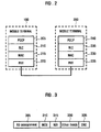
- FIG. 2 is a diagram illustrating a user plane protocol stack for use in LTE architecture of FIG. 1 .
- the mobile terminal 100 has a protocol stack composed of a Packet Data Convergence Protocol (PDCP) layer 205, a Radio Link Control (RLC) layer 210, a Media Access Control (MAC) layer 215, and a Physical (PHY) layer 220.
- PDCP Packet Data Convergence Protocol
- RLC Radio Link Control
- MAC Media Access Control
- PHY Physical
- the base station 200 has a protocol stack composed a PDPC layer 240, a RLC layer 235, a MAC layer 230, and a PHY layer 225.
- the PDCP layer 205 and 240 is responsible for IP header compression/decompression.
- the RLC layer 210 and 235 packs the PDCP Packet Data Units (PDUs) into a size appropriate for transmission and performs an Automatic Repeat reQuest (ARQ) function.
- the MAC layer 215 and 230 serves multiple RLC layer entities and multiplexes the RLC PDUs into a MAC PDU and de-multiplexes a MAC PDU into the RLC PDUs.
- the physical layer 220 and 225 performs encoding and modulation on the upper layer data to transmit through a radio channel and performs demodulation and decoding on the OFDM symbol received through radio channel to deliver to upper layers.
- one of the base station 200 and the UE can be a transmitter and the other of the base station 200 and the UE can be a receiver.
- the receiver fails to receive a packet (e.g., a MAC PDU) transmitted by the transmitter, the receiver transmits a Negative ACLnowledge (NACK) and the transmitter, upon receiving the NACK, retransmits the packet.
- NACK Negative ACLnowledge
- the receiver performs soft combining on the retransmitted packet and the previously received packet to improve data reliability.
- services can be provided in a completely IP-based and packet-based manner.
- the voice communication service can be served as a packet-based service rather than circuit-switched service.
- VoIP Voice over IP
- the traffic is characterized by small packet sizes with periodicity. For instance, when the VoIP service is provided in 12.2 Kbps Adaptive Multi-Rate (AMR) codec mode, VoIP packets having about 35-byte size are created every 20 msecs. Accordingly, in order to support the VoIP service with a normal scheduling scheme, the transmitter and receiver must exchange scheduling request messages and uplink resource allocation message whenever the VoIP packet is generated.
- AMR Adaptive Multi-Rate
- the base station 200 allocates semi-persistent resources to the mobile terminal 100 in order to reduce the control information overhead caused by the frequently transmitted scheduling requests and uplink resource allocation messages.
- This technique for reducing the control channel signaling by allocating semi-persistent resource is called Semi-Persistent resource Scheduling (SPS).
- the base station 200 transmits a resource allocation message whenever a packet to be transmitted is generated.
- a semi-persistent resource e.g., one or more resource blocks
- the resource is implicitly reused until a semi-persistent resource allocation message is transmitted.
- the mobile terminal 100 assumes a downlink transmission according to the semi-persistent resources that the UE has allocated and receives packets on the semi-persistent resources. Accordingly, the base station 200 does not need to transmit a semi-persistent resource allocation message when transmitting the packet using the semi-persistent resources allocated to the mobile terminal 100 but retransmission of the packet.
- the mobile terminal 100 cannot determine whether the currently received semi-persistent resource allocation message indicates a semi-persistent resource allocation (or reallocation), or determine whether the received semi-persistent resource allocation message indicates a resource allocation for retransmission of a packet using the semi-persistent resource.
- the UE can determine whether a semi-persistent resource allocation message indicates a semi-persistent resource allocation or a resource allocation for retransmitting a packet using the semi-persistent resource.
- a message structure for use in the resource allocation method according to embodiments of the present invention is described hereinafter.
- FIG. 3 is a diagram illustrating a format of a semi-persistent resource allocation message for use in the resource allocation method according to an embodiment of the present invention.
- the semi-persistent resource allocation message includes a Resource Block (RB) assignment field 305, a Modulation and Coding Scheme (MCS) field 310, a New Data Indicator (NDI) field 315, and a Cyclic Redundancy Check (CRC) field 335.
- the reference numeral 330 denotes other fields, which may include a HARQ process number field. In order to avoid unnecessarily obscuring the present invention, detailed descriptions of the other fields are omitted.
- the RB assignment field 305 contains the information on the amount and location of the resources assigned to the mobile terminal 100.
- the resource is allocated in units of Resource Blocks (RBs), which are 1 msec in duration, and consist of a predetermined number of subcarriers.
- RBs Resource Blocks
- At least one resource block is assigned is assigned by the RB assignment field 305.
- the at least one allocated resource block is a "transmission resource”.
- the MCS field contains information on the modulation level and channel coding rate adopted for transmission data.
- the MCS is 5 bits long and a code point represents a combination of a modulation scheme and channel coding rate.
- the MCS field 310 can indicate one of 32 code points including a pair a Quadrature Phase-Shift Keying (QPSK) (modulation scheme) and 0.11 (coding rate) to a 64 Quadrature Amplitude Modulation (QAM) and 0.95.
- QPSK Quadrature Phase-Shift Keying
- QAM Quadrature Amplitude Modulation
- the NDI field 315 is 1 bit long and used for indicating whether the resource allocation message indicates a semi-persistent resource allocation or a retransmission of a packet that has not been transmitted (or received). In an embodiment of the present invention, the NDI is set to "0" to indicate the semi-persistent resource allocation, or set to "1" to indicate the resource allocation for retransmission of a packet using the semi-persistent resource.
- the NDI field 315 contains information for identifying the semi-persistent resource allocation messages indicating semi-persistent resource allocation and resource allocation for retransmission of a packet using the semi-persistent resource.
- the UE can determine, based on the NDI value, whether the semi-persistent resource allocation message indicates a semi-persistent resource allocation or a resource allocation for retransmission of a packet, using the semi-persistent resource.
- the CRC field 325 carries a CRC value calculated for the information contained in the resource allocation message and a SPS Cell Radio Network Temporary Identifier (SPS C-RNTI).
- SPS C-RNTI is an identifier for the mobile terminal 100 for determining whether the semi-persistent resource allocation message is intended for the mobile terminal 100. Also, the SPS C-RNTI can be used for identifying the normal resource allocation message and the semi-persistent resource allocation message. Typically, the normal resource allocation message has a C-RNTI.
- the base station 200 can transmit resource allocation messages for allocating resource to the mobile terminal 100.
- the resource allocation messages can be classified into "semi-persistent resource allocation messages" and "normal resource allocation messages".
- the mobile terminal 100 can identify semi-persistent resource allocation messages by a CRC calculation.
- the normal message and semi-persistent resource allocation message can be identified depending on whether the message carries a C-RNTI or a SPS C-RNTI.
- C-RNTIs are carried by normal messages
- SPS C-RNTIs are carried by semi-persistent resource allocation messages.
- SPS C-RNTIs have a value for identifying a specific mobile terminal 100. Accordingly, the base station 200 transmits an SPS C-RNTI to the mobile terminal 100 in a call establishment process.
- the base station 200 When transmitting a semi-persistent resource allocation message to the mobile terminal 100, the base station 200 applies an SPS C-RNTI masking to the semi-persistent resource allocation message, performs a CRC calculation, and inserts the calculation result into the CRC field 525.
- the mobile terminal 100 applies a masking of the SPS C-RNTI received in the call establishment process to the received semi-persistent resource allocation message and performs CRC. If the CRC result matches the result calculated previously, the mobile terminal 100 determines that the semi-persistent resource allocation message intended for the mobile terminal 100 has been successfully received. This means that the semi-persistent resource allocation message has passed the CRC test.
- the mobile terminal 100 determines that a normal message intended for the mobile terminal 100 has been successfully received.
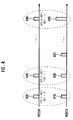
- FIG. 4 is a conceptual diagram illustrating a downlink data transmission using a resource allocation method in a mobile communication according to an embodiment of the present invention.
- a Physical Downlink Control Channel (PDCCH) and a Physical Downlink Shared Channel (PDSCH) are used for downlink transmission.
- the base station 200 transmits the semi-persistent resource allocation message on the PDCCH and data on the PDSCH.
- the mobile terminal 100 locates the semi-persistent resource based on the RB assignment information indicated by the semi-persistent resource allocation message. and the mobile terminal 100 further receives the packets by decoding the semi-persistent resource located on the PDSCH according to the MCS indicated by the semi-persistent resource allocation message.
- reference numbers 405, 415, and 430 denote semi-persistent resource allocation messages
- reference numbers 410, 420, 425, and 435 denote packets.
- the base station 200 transmits a semi-persistent resource allocation message 405 at a time point for assigning a semi-persistent resource to the mobile terminal 100.
- the base station 200 inserts a CRC calculation result into the CRC field 335 of the semi-persistent resource allocation message 405.
- the CRC calculation is performed with the SPS C-RNTI of the mobile terminal 100.
- the base station 200 also sets the NDI value contained in the NDI field 315 to "0.”
- the mobile terminal 100 verifies the semi-persistent resource allocation message 405 by referencing the NDI value, which is set to "0."
- the mobile terminal 100 locates the semi-persistent resource on the PDSCH and receives the packets 410 and 425 transmitted periodically in the semi-persistent resource that the mobile terminal 100 has been assigned.
- the mobile terminal 100 performs CRC test on every packet. In FIG. 4 it is assumed that the first packet 410 fails the CRC test. In this case, the mobile terminal 100 transmits a HARQ NACK to the base station 200.
- the base station 200 Upon receiving of the HARQ NACK, the base station 200 retransmits the erroneous packet using the semi-persistent resource assigned to the mobile terminal 100.
- the base station 200 generates a semi-persistent resource allocation message 415 having a CRC containing the CRC result calculated with the SPS C-RNTI of the mobile terminal 100 and NDI set to "1," which indicates that the retransmission resource allocation uses the semi-persistent resource.
- the mobile terminal 100 verifies the semi-persistent resource allocation message intended for the mobile terminal 100 based on the result of the CRC test, and checks the NDI field 315 of the semi-persistent resource allocation message. The mobile terminal 100 determines, by referencing to the NDI set to "1," that the semi-persistent resource allocation message 415 indicates that the retransmission resource allocation uses the semi-persistent resource.
- the mobile terminal 100 locates the retransmission resource based on the RB assignment information contained in the RB assignment field of the semi-persistent resource allocation message 415 and receives the retransmitted packet 420 in the retransmission resource. Next, the mobile terminal 100 performs HARQ soft while combining the retransmitted packet 420 with the previously received packet 410.
- the base station 200 If the base station 200 changes the semi-persistent resource assigned to the mobile terminal 100, the base station 200 transmits a semi-persistent resource allocation message 430 indicating a semi-persistent resource allocation to the mobile terminal 100.
- the semi-persistent resource allocation message 430 includes CRC field 335 containing a CRC result calculated with the SPS C-RNTI of the mobile terminal 100 and the NDI field 315 containing NDI value set to "0," in order to indicate that the semi-persistent resource allocation message indicates the semi-persistent resource allocation.
- the mobile terminal 100 verifies the semi-persistent resource allocation message according to the positive result of the CRC test and determines, by referencing the NDI value that is set to "0," that the semi-persistent resource allocation message indicates the semi-persistent resource allocation. Accordingly, the mobile terminal 100 locates the semi-persistent resource indicated by the RB assignment information contained in the RB assignment field of the semi-persistent resource allocation message and receives the first packets 435 transmitted periodically in the semi-persistent resource allocated to the mobile terminal 100.
- the mobile terminal can discriminate the semi-persistent resource allocation messages indicating retransmission resource allocation and semi-persistent resource allocation accurately, based on the value of the NDI contained in the NDI field 315 of the semi-persistent resource allocation message.
- the resource allocation method negates the need for supplementary information such as "NDI_LATEST" that is updated for indicating whether the packet is a first packet or a retransmitted packet, in which enhances signaling reliability and system efficiency.
- the semi-persistent resource allocation message can be used for allocating a semi-persistent resource and a retransmission resource using the semi-persistent resource to the mobile terminal 100.
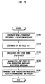
- FIG. 5 is a flowchart illustrating a semi-persistent resource allocation procedure of a resource allocation method according to an embodiment of the present invention
- FIG. 6 is a flowchart illustrating a retransmission resource allocation procedure of the resource allocation method according to an embodiment of the present invention.
- the base station determines whether to transmit a semi-persistent resource allocation message indicating a semi-persistent resource allocation or a semi-persistent resource allocation message indicative of retransmission resource allocation using the semi-persistent resource.
- the base station When transmitting the semi-persistent resource allocation message indicating a semi-persistent resource allocation, the base station performs the semi-persistent resource allocation procedure depicted in FIG. 5 . Otherwise, when transmitting the semi-persistent resource allocation message indicating a retransmission resource allocation using the semi-persistent resource, the base station performs the retransmission resource allocation procedure depicted in FIG. 6 .
- the base station 200 in order to allocate a semi-persistent resource, the base station 200 first creates a semi-persistent resource allocation message based on the information on the semi-persistent resource to be allocated to the mobile terminal 100, in step 505.
- the information on the semi-persistent resource assigned to the mobile terminal 100 is specified in the RB assignment field 305 of the semi-persistent resource allocation message.
- the base station 200 sets the NDI value contained in the NDI field 315 of the semi-persistent resource message to "0," in step 510.
- the base station 200 calculates a CRC code with the SPS C-RNTI of the mobile terminal 100, in step 515.
- the CRC code calculated with the SPS C-RNTI can be used to identify the normal resource allocation message and the semi-persistent resource allocation message.
- the base station 200 inserts the CRC code into the CRC field 335 of the semi-persistent resource allocation message, in step 520.
- the base station 200 sets the NDI value contained in the NDI field 315 of the semi-persistent resource allocation message to "0," so as to inform the mobile terminal 100 that semi-persistent resource allocation message is indicative of semi-persistent resource allocation.
- a procedure for allocating a retransmission resource using the semi-persistent resource allocated to the mobile terminal 100 is described hereinafter with reference to FIG. 6 .
- the base station allocates a retransmission resource for retransmitting the packet indicated by the HARQ NACK message.
- the base station 200 in order to allocate a retransmission resource using the semi-persistent resource allocated to the mobile terminal 100, the base station 200 creates a semi-persistent resource allocation message based on the information on the retransmission resource to be allocated to the mobile terminal 100, in step 650.
- the information on the retransmission resource assigned to the mobile terminal 100 is specified in the RB assignment field 305 of the semi-persistent resource allocation message.
- the base station 200 sets the NDI value contained in the NDI field 315 of the semi-persistent resource allocation message to "1," in step 610.
- the base station 200 calculates a CRC code with the SPS C-RNTI of the mobile terminal 100, in step 615.
- the CRC code calculated with the SPS C-RNTI allows the mobile terminal 100 to distinguish the semi-persistent resource allocation message from the normal resource allocation message.
- the base station 200 inserts the CRC code into the CRC field 335 of the semi-persistent resource allocation message, in step 620.
- the base station 200 transmits the semi-persistent resource allocation message to the mobile terminal 100 via a PDCCH.
- the base station 200 sets the NDI value contained in the NDI field 315 of the semi-persistent resource allocation message to "1," so as to inform the mobile terminal 100 that semi-persistent resource allocation message indicates a retransmission resource allocation.
- FIG. 7 is a flowchart illustrating a resource allocation message discrimination procedure of a resource allocation method according to an embodiment of the present invention.
- the mobile terminal 100 monitors the PDCCH, in step 705.
- the mobile terminal 100 calculates the CRC code with the C-RNTI and SPS C-RNTI and compares the calculated CRC code with the one received from the base station to determine whether the message is intended for the mobile terminal 100.
- the mobile terminal 100 determines whether the message is a normal resource allocation message or a semi-persistent resource allocation message according to whether the message has passed the CRC test with the C-RNTI or the SPS C-RNTI. In FIG. 7 , it is assumed that the message has passed the CRC test with the SPS C-RNTI. This means the received message is a semi-persistent resource allocation message.
- the mobile terminal 100 receives the semi-persistent resource allocation message, in step 710, and checks the NDI field of the semi-persistent resource allocation message to determine whether the semi-persistent resource allocation message indicates a semi-persistent resource allocation or a retransmission resource allocation, in step 715.
- the CRC calculation is performed on the received message with a masking of the SPS C-RNTI of the mobile station 100. If the CRC code obtained from the CRC calculation is compared with the CRC code received from the base station, the CRC success.
- the mobile terminal 100 determines that the semi-persistent resource allocation message indicates a retransmission resource allocation, in step 720. Otherwise, if the NDI value is set to "0," the mobile terminal 100 determines that the semi-persistent resource allocation message indicates a semi-persistent resource allocation, in step 730.
- the mobile terminal 100 receives the packet retransmitted in the resource of the PDSCH that is indicated by the RB assignment information of the semi-persistent resource allocation message, and soft-combines the packet stored in the HARQ buffer with the retransmitted packet in the HARQ process.
- the mobile terminal 100 locates the semi-persistent resource indicated by the semi-persistent resource allocation message.
- the mobile terminal 100 checks the information contained the RB assignment field 305 of the semi-persistent resource allocation message indicating the semi-persistent resource allocation and registers the resource indicated by the RB assignment information as the semi-persistent resource allocated to the mobile terminal 100.
- the mobile terminal 100 changes the previous semi-persistent resource to the newly allocated semi-persistent resource.
- FIG. 8 is a schematic block diagram illustrating a configuration of a mobile terminal according to an embodiment of the present invention.
- the mobile terminal 100 includes an upper layer device 805, an HARQ device 810, an SPS resource controller 820, a transceiver 825, and a PDCCH processor 830.
- the transceiver 825 is responsible for transmitting and receiving radio signal carrying data. Particularly, the transceiver 825 receives data (control information) through the PDCCH. Once the data is received through the PDCCH, the transceiver 825 decodes the resource allocated to the mobile terminal on the PDCCH into data and delivers the decoded data to the PDCCH processor 830.
- the data includes a semi-persistent resource allocation message.
- the PDCCH processor 830 performs a CRC test on the semi-persistent resource allocation message with a masking of the SPS C-RNTI of the mobile terminal.
- the SPS C-RNTI is a dynamic UE identifier allocated by a serving base station. According to an embodiment of the present invention, the SPS C-RNTI is also used for determining whether the message message is a normal resource allocation message or a semi-persistent resource allocation message.
- the PDCCH processor determines that the data is a semi-persistent resource allocation message intended for the mobile terminal 100, and sends the semi-persistent resource allocation message to the SPS resource controller 820.
- the SPS resource controller 820 checks the NDI field 315 of the semi-persistent resource allocation message received from the PDCCH processor 830 and determines whether the semi-persistent resource allocation message indicates a semi-persistent resource allocation or a retransmission resource allocation on the basis of the NDI value contained in the NDI field 315.
- the SPS resource controller 820 determines that the semi-persistent resource allocation message indicates a retransmission resource allocation. In this case, the SPS resource controller 820 controls the HARQ device 810 to combine the packet received in the resource allocated on the PDSCH by the semi-persistent resource allocation message indicative of retransmission resource allocation with the previously received packet stored in the HARQ buffer.
- the SPS resource controller 820 determines that the semi-persistent resource allocation message indicates a semi-persistent resource allocation. In this case, SPS resource controller 820 registers the semi-persistent resource indicated by the semi-persistent resource allocation message.
- the mobile terminal 100 locates the semi-persistent resource indicated by the RB assignment field 305 of the semi-persistent resource allocation message and decodes the semi-persistent resources on the PDSCH(s), since the semi-persistent resource allocation message has been received.
- the SPS resource controller 820 replaces the previously allocated semi-persistent resource with the newly allocated semi-persistent resource. Accordingly, the mobile terminal decodes the newly allocates semi-persistent resource on the PDSCH(s) to receive packets.
- the HARQ device 810 includes a plurality of HARQ processors that are operating in individual HARQ processes, respectively. Each HARQ processor performs HARQ operations to request retransmission of packet and soft combining on the retransmitted packet and the previously received packet stored in the corresponding HARQ buffer.
- the upper layer device 805 includes at least one of Radio Link Control (RLC) device, Packet Data Convergence Protocol (PDCP) device, and Media Access Control (MAC) device.
- RLC Radio Link Control
- PDCP Packet Data Convergence Protocol
- MAC Media Access Control
- the PDCP device is responsible for compressing/decompressing IP header
- the RLC device formats the PDCP PDUs in size appropriate for transporting
- the MAC device multiplexes and demultiplexes MAC PDUs.
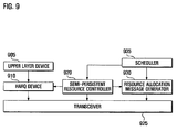
- FIG. 9 is a schematic block diagram illustrating a configuration of a base station according to an embodiment of the present invention.
- the base station includes an upper layer device 905, an HARQ device 910, a transceiver 925, an SPS resource controller 920, resource allocation message generator 930, and a scheduler 935.
- the transceiver 925 is responsible for transmitting and receiving radio signal carrying data. Particularly, the transceiver 925 transmits data (control information) on the PDCCH.
- the data include a semi-persistent resource allocation message.
- the resource allocation message generator 930 generates a semi-persistent resource allocation message and delivers the semi-persistent resource allocation message to the transceiver 925 under the control of the scheduler 935 and the SPS resource controller 920.
- the scheduler 935 allocates resources to the mobile terminal 100 in consideration of the amount, type, and usage of the data to be transmitted to the mobile terminal 100. Particularly, according to the embodiment of the present invention illustrated in FIG. 9 , the scheduler 935 can allocate resources to mobile terminals in normal resource scheduling manner and semi-persistent resource scheduling manner.
- the scheduler 935 controls the resource allocation message generator 930 to generate a resource allocation message according to the types of identifiers and the usages of the resources to be allocated to the mobile terminals.
- the scheduler 935 notifies the semi-persistent resource controller 920.
- the semi-persistent resource controller 920 controls the resource allocation message generator 930 to set the NDI value contained in the NDI field 315 of the semi-persistent resource allocation message to "0."
- the semi-persistent resource controller 920 also controls the transceiver 925 to transmit the packet using the semi-persistent resource allocated to the mobile terminal 100 on the PDSCH.
- the semi-persistent resource controller 920 controls the resource allocation message generator 930 to set the NDI value contained in the NDI field 315 of the semi-persistent resource allocation message to "1."
- the semi-persistent resource controller 920 also controls the transceiver 925 to retransmit the packet requested by the mobile terminal using the semi-persistent resource allocated on the PDSCH.
- the semi-persistent resource controller 920 controls the resource allocation message generator 930 to set the NDI carried by the semi-persistent resource allocation message to "0" or "1,” according to whether the resource allocation is a semi-persistent resource allocation or a retransmission resource allocation using the semi-persistent resource.
- the semi-persistent resource controller 920 calculates a CRC code with the SPS C-RNTI of the mobile terminal to allocate the semi-persistent resource and inserts the calculated CRC code into the CRC field 335.
- the HARQ device 910 includes a plurality of HARQ processors that are operating in individual HARQ processes, respectively. Each HARQ processor performs HARQ operations to request retransmission of a packet and soft combining on the retransmitted packet and the previously received packet stored in the corresponding HARQ buffer.
- the upper layer device 905 includes at least one of Radio Link Control (RLC) device, Packet Data Convergence Protocol (PDCP) device, and Media Access Control (MAC) device.
- RLC Radio Link Control
- PDCP Packet Data Convergence Protocol
- MAC Media Access Control
- the PDCP device is responsible for compressing/decompressing IP header
- the RLC device formats the PDCP PDUs in size appropriate for transporting
- the MAC device multiplexes and demultiplexes MAC PDUs.
- the resource allocation method for a wireless communication system uses a semi-persistent resource allocation message having usage information that indicates whether the semi-persistent resource allocation message is indicative of semi-persistent resource allocation or retransmission resource allocation using the semi-persistent resource, thereby enhancing the reliability of retransmission using the semi-persistent resource. Also, the resource allocation method of the present invention enables the mobile terminal to check the resource allocation for retransmission without recording the status of packet, thereby reducing processing complexity of the mobile terminal.
Landscapes
- Engineering & Computer Science (AREA)
- Computer Networks & Wireless Communication (AREA)
- Signal Processing (AREA)
- Mobile Radio Communication Systems (AREA)
- Error Detection And Correction (AREA)
Priority Applications (1)
| Application Number | Priority Date | Filing Date | Title |
|---|---|---|---|
| EP14153055.0A EP2731393B1 (en) | 2008-08-12 | 2009-08-11 | Retransmission resource allocation method and apparatus for wireless communication system |
Applications Claiming Priority (1)
| Application Number | Priority Date | Filing Date | Title |
|---|---|---|---|
| KR1020080078918A KR101481430B1 (ko) | 2008-08-12 | 2008-08-12 | 무선 통신 시스템의 데이터 재전송 자원 할당 방법 및 장치 |
Related Child Applications (2)
| Application Number | Title | Priority Date | Filing Date |
|---|---|---|---|
| EP14153055.0A Division EP2731393B1 (en) | 2008-08-12 | 2009-08-11 | Retransmission resource allocation method and apparatus for wireless communication system |
| EP14153055.0A Division-Into EP2731393B1 (en) | 2008-08-12 | 2009-08-11 | Retransmission resource allocation method and apparatus for wireless communication system |
Publications (2)
| Publication Number | Publication Date |
|---|---|
| EP2154924A1 EP2154924A1 (en) | 2010-02-17 |
| EP2154924B1 true EP2154924B1 (en) | 2014-03-12 |
Family
ID=41394959
Family Applications (2)
| Application Number | Title | Priority Date | Filing Date |
|---|---|---|---|
| EP14153055.0A Active EP2731393B1 (en) | 2008-08-12 | 2009-08-11 | Retransmission resource allocation method and apparatus for wireless communication system |
| EP20090167616 Active EP2154924B1 (en) | 2008-08-12 | 2009-08-11 | Retransmission resource allocation method for wireless communication system |
Family Applications Before (1)
| Application Number | Title | Priority Date | Filing Date |
|---|---|---|---|
| EP14153055.0A Active EP2731393B1 (en) | 2008-08-12 | 2009-08-11 | Retransmission resource allocation method and apparatus for wireless communication system |
Country Status (7)
| Country | Link |
|---|---|
| US (1) | US20100042886A1 (ru) |
| EP (2) | EP2731393B1 (ru) |
| JP (2) | JP2011530943A (ru) |
| KR (1) | KR101481430B1 (ru) |
| CN (2) | CN103857047B (ru) |
| RU (1) | RU2501165C2 (ru) |
| WO (1) | WO2010018990A2 (ru) |
Families Citing this family (19)
| Publication number | Priority date | Publication date | Assignee | Title |
|---|---|---|---|---|
| WO2009041785A2 (en) * | 2007-09-28 | 2009-04-02 | Lg Electronics Inc. | Method for detecting control information in wireless communication system |
| WO2009120001A2 (en) | 2008-03-24 | 2009-10-01 | Lg Electronics Inc. | Method for configuring different data block formats for downlink and uplink |
| US8446859B2 (en) * | 2008-02-01 | 2013-05-21 | Lg Electronics Inc. | Method for controlling uplink load in cell— FACH state |
| JP4926279B2 (ja) * | 2008-03-21 | 2012-05-09 | エルジー エレクトロニクス インコーポレイティド | 無線通信システムにおけるデータ通信方法 |
| JP5154523B2 (ja) * | 2008-08-27 | 2013-02-27 | 創新音▲速▼股▲ふん▼有限公司 | Sps機能のharqプロセスを処理する方法及び装置 |
| US8305887B2 (en) * | 2009-09-24 | 2012-11-06 | Cisco Technology, Inc. | Selective defragmentation of quadrature amplitude modulators |
| US8873483B2 (en) * | 2010-06-03 | 2014-10-28 | Htc Corporation | Method of handling semi-persistent scheduling cell radio network temporary identifier and related communication device |
| GB2484342B (en) * | 2010-10-08 | 2015-04-29 | Sca Ipla Holdings Inc | Communications systems, communications device, infrastructure equipment and method |
| EP2806681A4 (en) * | 2012-01-19 | 2016-01-27 | Kyocera Corp | MOBILE COMMUNICATION SYSTEM, BASE STATION, COMP CONTROL DEVICE, AND COMMUNICATION CONTROL METHOD |
| CN103442443B (zh) * | 2013-08-14 | 2016-07-06 | 大唐移动通信设备有限公司 | 一种半静态资源的传输检测方法和装置 |
| CN105681439A (zh) * | 2016-01-29 | 2016-06-15 | 宇龙计算机通信科技(深圳)有限公司 | 用于车辆通信的资源调度方法、装置、终端和基站 |
| AR108456A1 (es) | 2016-05-13 | 2018-08-22 | Ericsson Telefon Ab L M | Retransmisión de paquetes en un sistema de comunicaciones inalámbricas |
| WO2017213374A1 (en) | 2016-06-07 | 2017-12-14 | Samsung Electronics Co., Ltd. | Method and device for providing different services in mobile communication system |
| KR102401339B1 (ko) * | 2016-06-07 | 2022-05-25 | 삼성전자 주식회사 | 이동 통신 시스템에서 이종 서비스 제공 방법 및 장치 |
| WO2018165872A1 (zh) * | 2017-03-14 | 2018-09-20 | 广东欧珀移动通信有限公司 | 用于确定基础参数集的方法、终端和网络设备 |
| CN109219024B (zh) * | 2017-06-30 | 2021-08-13 | 华为技术有限公司 | 数据传输方法及装置 |
| AU2017427108A1 (en) * | 2017-08-11 | 2019-12-19 | Guangdong Oppo Mobile Telecommunications Corp., Ltd. | Method for processing semi persistent scheduling, communication device, and storage medium |
| CN111511033B (zh) * | 2019-01-30 | 2022-02-08 | 华为技术有限公司 | 用于短周期半静态调度的资源配置方法和装置 |
| EP4241518A4 (en) * | 2020-11-04 | 2024-10-02 | Qualcomm Incorporated | UPLINK CONTROL RESOURCE DETERMINATION FOR SCHEDULED COMMUNICATIONS WITH DELAYED FEEDBACK REPORTING |
Family Cites Families (18)
| Publication number | Priority date | Publication date | Assignee | Title |
|---|---|---|---|---|
| EP1261227A1 (en) * | 2001-05-21 | 2002-11-27 | Motorola, Inc. | Method and apparatus for increased information transfer in a communication system |
| US7352722B2 (en) * | 2002-05-13 | 2008-04-01 | Qualcomm Incorporated | Mitigation of link imbalance in a wireless communication system |
| JP2006203337A (ja) * | 2005-01-18 | 2006-08-03 | Matsushita Electric Ind Co Ltd | リソース割当方法及び基地局装置 |
| KR101137327B1 (ko) * | 2005-05-06 | 2012-04-19 | 엘지전자 주식회사 | 상향링크 채널 스케쥴링을 위한 제어정보 전송 방법 및상향링크 채널 스케쥴링 방법 |
| US7904055B2 (en) * | 2005-08-23 | 2011-03-08 | Lg Electronics Inc. | Communicating message in mobile communication system |
| WO2007092245A2 (en) * | 2006-02-03 | 2007-08-16 | Interdigital Technology Corporation | Quality of service based resource determination and allocation apparatus and procedure in high speed packet access evolution and long term evolution systems |
| US8848618B2 (en) * | 2006-08-22 | 2014-09-30 | Qualcomm Incorporated | Semi-persistent scheduling for traffic spurts in wireless communication |
| KR101347404B1 (ko) * | 2006-10-05 | 2014-01-02 | 엘지전자 주식회사 | 무선통신 시스템에서 음성 패킷의 전송 방법 |
| TW201251496A (en) * | 2006-12-28 | 2012-12-16 | Interdigital Tech Corp | Efficient uplink operation with high instantaneous data rates |
| EP2109952B1 (en) * | 2007-02-09 | 2015-07-08 | Nokia Technologies Oy | Method and apparatus for acknowledgement signaling |
| ES2950290T3 (es) * | 2007-08-13 | 2023-10-06 | Optis Cellular Tech Llc | Procedimiento para controlar un esquema de programación |
| WO2009041785A2 (en) * | 2007-09-28 | 2009-04-02 | Lg Electronics Inc. | Method for detecting control information in wireless communication system |
| US8739013B2 (en) * | 2007-09-28 | 2014-05-27 | Lg Electronics Inc. | Method for detecting control information in wireless communication system |
| CN102067500B (zh) * | 2008-03-20 | 2014-01-15 | 诺基亚公司 | 通信系统中的用于持久分配的分组的新数据指示符 |
| JP4926279B2 (ja) * | 2008-03-21 | 2012-05-09 | エルジー エレクトロニクス インコーポレイティド | 無線通信システムにおけるデータ通信方法 |
| WO2009149400A1 (en) * | 2008-06-06 | 2009-12-10 | Research In Motion Limited | Hybrid automatic repeat request associations for downlink semi-persistent scheduling |
| US9100179B2 (en) * | 2008-09-10 | 2015-08-04 | Qualcomm Incorporated | Method and apparatus for managing a new data indicator in a wireless communication system |
| EP2166804A1 (en) * | 2008-09-17 | 2010-03-24 | Panasonic Corporation | Deactivation of semi-persistent resource allocations in a mobile communication network |
-
2008
- 2008-08-12 KR KR1020080078918A patent/KR101481430B1/ko active IP Right Grant
-
2009
- 2009-08-11 EP EP14153055.0A patent/EP2731393B1/en active Active
- 2009-08-11 EP EP20090167616 patent/EP2154924B1/en active Active
- 2009-08-12 CN CN201410121351.8A patent/CN103857047B/zh active Active
- 2009-08-12 RU RU2011105142/07A patent/RU2501165C2/ru active
- 2009-08-12 CN CN200980136296.7A patent/CN102160304B/zh active Active
- 2009-08-12 JP JP2011522905A patent/JP2011530943A/ja active Pending
- 2009-08-12 US US12/540,039 patent/US20100042886A1/en not_active Abandoned
- 2009-08-12 WO PCT/KR2009/004494 patent/WO2010018990A2/en active Application Filing
-
2015
- 2015-07-23 JP JP2015146149A patent/JP6090871B2/ja active Active
Also Published As
| Publication number | Publication date |
|---|---|
| WO2010018990A2 (en) | 2010-02-18 |
| CN103857047B (zh) | 2018-01-05 |
| CN102160304A (zh) | 2011-08-17 |
| EP2154924A1 (en) | 2010-02-17 |
| JP2016026417A (ja) | 2016-02-12 |
| RU2501165C2 (ru) | 2013-12-10 |
| JP2011530943A (ja) | 2011-12-22 |
| CN102160304B (zh) | 2014-04-23 |
| KR101481430B1 (ko) | 2015-01-12 |
| WO2010018990A3 (en) | 2010-06-03 |
| KR20100020225A (ko) | 2010-02-22 |
| EP2731393B1 (en) | 2017-06-07 |
| US20100042886A1 (en) | 2010-02-18 |
| JP6090871B2 (ja) | 2017-03-08 |
| EP2731393A1 (en) | 2014-05-14 |
| RU2011105142A (ru) | 2012-08-20 |
| CN103857047A (zh) | 2014-06-11 |
Similar Documents
| Publication | Publication Date | Title |
|---|---|---|
| EP2154924B1 (en) | Retransmission resource allocation method for wireless communication system | |
| US11403193B2 (en) | Transmission control method for HARQ in mobile communication system | |
| US9220093B2 (en) | Method of supporting data retransmission in a mobile communication system | |
| US7830837B2 (en) | Method of data communication in a wireless communication system | |
| CN103648169B (zh) | 释放半静态资源分配的方法和用户设备 | |
| US8493920B2 (en) | Method for transmitting voice packets in wireless communication system | |
| KR101478240B1 (ko) | 무선 통신 시스템의 자원 할당 방법 및 이를 위한 무선통신 시스템 | |
| WO2009053930A2 (en) | Improved re-transmission capability in semi-persistent transmission | |
| JP2010522467A (ja) | セミパーシステント・スケジューリングのための(h)arq | |
| WO2013071754A1 (zh) | 下行控制信息传输方法和系统 | |
| WO2007108602A1 (en) | Method and apparatus for allocation of transmission resources in a mobile communication system | |
| EP2192813A1 (en) | Method and apparatus for releasing reserved resources | |
| KR101298580B1 (ko) | 이동통신 시스템에서 패킷 서비스를 위한 패킷 디코딩정보의 송수신 방법 및 장치 |
Legal Events
| Date | Code | Title | Description |
|---|---|---|---|
| PUAI | Public reference made under article 153(3) epc to a published international application that has entered the european phase |
Free format text: ORIGINAL CODE: 0009012 |
|
| AK | Designated contracting states |
Kind code of ref document: A1 Designated state(s): AT BE BG CH CY CZ DE DK EE ES FI FR GB GR HR HU IE IS IT LI LT LU LV MC MK MT NL NO PL PT RO SE SI SK SM TR |
|
| AX | Request for extension of the european patent |
Extension state: AL BA RS |
|
| 17P | Request for examination filed |
Effective date: 20100729 |
|
| 17Q | First examination report despatched |
Effective date: 20100824 |
|
| RAP1 | Party data changed (applicant data changed or rights of an application transferred) |
Owner name: SAMSUNG ELECTRONICS CO., LTD. |
|
| GRAP | Despatch of communication of intention to grant a patent |
Free format text: ORIGINAL CODE: EPIDOSNIGR1 |
|
| INTG | Intention to grant announced |
Effective date: 20130920 |
|
| GRAS | Grant fee paid |
Free format text: ORIGINAL CODE: EPIDOSNIGR3 |
|
| GRAA | (expected) grant |
Free format text: ORIGINAL CODE: 0009210 |
|
| AK | Designated contracting states |
Kind code of ref document: B1 Designated state(s): AT BE BG CH CY CZ DE DK EE ES FI FR GB GR HR HU IE IS IT LI LT LU LV MC MK MT NL NO PL PT RO SE SI SK SM TR |
|
| REG | Reference to a national code |
Ref country code: GB Ref legal event code: FG4D |
|
| REG | Reference to a national code |
Ref country code: CH Ref legal event code: EP |
|
| REG | Reference to a national code |
Ref country code: AT Ref legal event code: REF Ref document number: 656992 Country of ref document: AT Kind code of ref document: T Effective date: 20140315 |
|
| REG | Reference to a national code |
Ref country code: IE Ref legal event code: FG4D |
|
| REG | Reference to a national code |
Ref country code: DE Ref legal event code: R096 Ref document number: 602009022355 Country of ref document: DE Effective date: 20140424 |
|
| REG | Reference to a national code |
Ref country code: NL Ref legal event code: T3 |
|
| REG | Reference to a national code |
Ref country code: SE Ref legal event code: TRGR |
|
| PG25 | Lapsed in a contracting state [announced via postgrant information from national office to epo] |
Ref country code: LT Free format text: LAPSE BECAUSE OF FAILURE TO SUBMIT A TRANSLATION OF THE DESCRIPTION OR TO PAY THE FEE WITHIN THE PRESCRIBED TIME-LIMIT Effective date: 20140312 Ref country code: NO Free format text: LAPSE BECAUSE OF FAILURE TO SUBMIT A TRANSLATION OF THE DESCRIPTION OR TO PAY THE FEE WITHIN THE PRESCRIBED TIME-LIMIT Effective date: 20140612 |
|
| REG | Reference to a national code |
Ref country code: AT Ref legal event code: MK05 Ref document number: 656992 Country of ref document: AT Kind code of ref document: T Effective date: 20140312 |
|
| REG | Reference to a national code |
Ref country code: LT Ref legal event code: MG4D |
|
| PG25 | Lapsed in a contracting state [announced via postgrant information from national office to epo] |
Ref country code: CY Free format text: LAPSE BECAUSE OF FAILURE TO SUBMIT A TRANSLATION OF THE DESCRIPTION OR TO PAY THE FEE WITHIN THE PRESCRIBED TIME-LIMIT Effective date: 20140312 |
|
| PG25 | Lapsed in a contracting state [announced via postgrant information from national office to epo] |
Ref country code: HR Free format text: LAPSE BECAUSE OF FAILURE TO SUBMIT A TRANSLATION OF THE DESCRIPTION OR TO PAY THE FEE WITHIN THE PRESCRIBED TIME-LIMIT Effective date: 20140312 Ref country code: LV Free format text: LAPSE BECAUSE OF FAILURE TO SUBMIT A TRANSLATION OF THE DESCRIPTION OR TO PAY THE FEE WITHIN THE PRESCRIBED TIME-LIMIT Effective date: 20140312 |
|
| PG25 | Lapsed in a contracting state [announced via postgrant information from national office to epo] |
Ref country code: BE Free format text: LAPSE BECAUSE OF FAILURE TO SUBMIT A TRANSLATION OF THE DESCRIPTION OR TO PAY THE FEE WITHIN THE PRESCRIBED TIME-LIMIT Effective date: 20140312 Ref country code: IS Free format text: LAPSE BECAUSE OF FAILURE TO SUBMIT A TRANSLATION OF THE DESCRIPTION OR TO PAY THE FEE WITHIN THE PRESCRIBED TIME-LIMIT Effective date: 20140712 Ref country code: EE Free format text: LAPSE BECAUSE OF FAILURE TO SUBMIT A TRANSLATION OF THE DESCRIPTION OR TO PAY THE FEE WITHIN THE PRESCRIBED TIME-LIMIT Effective date: 20140312 Ref country code: CZ Free format text: LAPSE BECAUSE OF FAILURE TO SUBMIT A TRANSLATION OF THE DESCRIPTION OR TO PAY THE FEE WITHIN THE PRESCRIBED TIME-LIMIT Effective date: 20140312 Ref country code: RO Free format text: LAPSE BECAUSE OF FAILURE TO SUBMIT A TRANSLATION OF THE DESCRIPTION OR TO PAY THE FEE WITHIN THE PRESCRIBED TIME-LIMIT Effective date: 20140312 Ref country code: BG Free format text: LAPSE BECAUSE OF FAILURE TO SUBMIT A TRANSLATION OF THE DESCRIPTION OR TO PAY THE FEE WITHIN THE PRESCRIBED TIME-LIMIT Effective date: 20140612 |
|
| PG25 | Lapsed in a contracting state [announced via postgrant information from national office to epo] |
Ref country code: AT Free format text: LAPSE BECAUSE OF FAILURE TO SUBMIT A TRANSLATION OF THE DESCRIPTION OR TO PAY THE FEE WITHIN THE PRESCRIBED TIME-LIMIT Effective date: 20140312 Ref country code: ES Free format text: LAPSE BECAUSE OF FAILURE TO SUBMIT A TRANSLATION OF THE DESCRIPTION OR TO PAY THE FEE WITHIN THE PRESCRIBED TIME-LIMIT Effective date: 20140312 Ref country code: PL Free format text: LAPSE BECAUSE OF FAILURE TO SUBMIT A TRANSLATION OF THE DESCRIPTION OR TO PAY THE FEE WITHIN THE PRESCRIBED TIME-LIMIT Effective date: 20140312 Ref country code: SK Free format text: LAPSE BECAUSE OF FAILURE TO SUBMIT A TRANSLATION OF THE DESCRIPTION OR TO PAY THE FEE WITHIN THE PRESCRIBED TIME-LIMIT Effective date: 20140312 |
|
| REG | Reference to a national code |
Ref country code: DE Ref legal event code: R097 Ref document number: 602009022355 Country of ref document: DE |
|
| PG25 | Lapsed in a contracting state [announced via postgrant information from national office to epo] |
Ref country code: PT Free format text: LAPSE BECAUSE OF FAILURE TO SUBMIT A TRANSLATION OF THE DESCRIPTION OR TO PAY THE FEE WITHIN THE PRESCRIBED TIME-LIMIT Effective date: 20140714 |
|
| PLBE | No opposition filed within time limit |
Free format text: ORIGINAL CODE: 0009261 |
|
| STAA | Information on the status of an ep patent application or granted ep patent |
Free format text: STATUS: NO OPPOSITION FILED WITHIN TIME LIMIT |
|
| PG25 | Lapsed in a contracting state [announced via postgrant information from national office to epo] |
Ref country code: DK Free format text: LAPSE BECAUSE OF FAILURE TO SUBMIT A TRANSLATION OF THE DESCRIPTION OR TO PAY THE FEE WITHIN THE PRESCRIBED TIME-LIMIT Effective date: 20140312 |
|
| 26N | No opposition filed |
Effective date: 20141215 |
|
| REG | Reference to a national code |
Ref country code: DE Ref legal event code: R097 Ref document number: 602009022355 Country of ref document: DE Effective date: 20141215 |
|
| PG25 | Lapsed in a contracting state [announced via postgrant information from national office to epo] |
Ref country code: LU Free format text: LAPSE BECAUSE OF FAILURE TO SUBMIT A TRANSLATION OF THE DESCRIPTION OR TO PAY THE FEE WITHIN THE PRESCRIBED TIME-LIMIT Effective date: 20140811 Ref country code: MC Free format text: LAPSE BECAUSE OF FAILURE TO SUBMIT A TRANSLATION OF THE DESCRIPTION OR TO PAY THE FEE WITHIN THE PRESCRIBED TIME-LIMIT Effective date: 20140312 |
|
| REG | Reference to a national code |
Ref country code: CH Ref legal event code: PL |
|
| PG25 | Lapsed in a contracting state [announced via postgrant information from national office to epo] |
Ref country code: LI Free format text: LAPSE BECAUSE OF NON-PAYMENT OF DUE FEES Effective date: 20140831 Ref country code: CH Free format text: LAPSE BECAUSE OF NON-PAYMENT OF DUE FEES Effective date: 20140831 |
|
| REG | Reference to a national code |
Ref country code: IE Ref legal event code: MM4A |
|
| PG25 | Lapsed in a contracting state [announced via postgrant information from national office to epo] |
Ref country code: SI Free format text: LAPSE BECAUSE OF FAILURE TO SUBMIT A TRANSLATION OF THE DESCRIPTION OR TO PAY THE FEE WITHIN THE PRESCRIBED TIME-LIMIT Effective date: 20140312 |
|
| PG25 | Lapsed in a contracting state [announced via postgrant information from national office to epo] |
Ref country code: IE Free format text: LAPSE BECAUSE OF NON-PAYMENT OF DUE FEES Effective date: 20140811 |
|
| PG25 | Lapsed in a contracting state [announced via postgrant information from national office to epo] |
Ref country code: SM Free format text: LAPSE BECAUSE OF FAILURE TO SUBMIT A TRANSLATION OF THE DESCRIPTION OR TO PAY THE FEE WITHIN THE PRESCRIBED TIME-LIMIT Effective date: 20140312 |
|
| PG25 | Lapsed in a contracting state [announced via postgrant information from national office to epo] |
Ref country code: GR Free format text: LAPSE BECAUSE OF FAILURE TO SUBMIT A TRANSLATION OF THE DESCRIPTION OR TO PAY THE FEE WITHIN THE PRESCRIBED TIME-LIMIT Effective date: 20140613 Ref country code: MT Free format text: LAPSE BECAUSE OF FAILURE TO SUBMIT A TRANSLATION OF THE DESCRIPTION OR TO PAY THE FEE WITHIN THE PRESCRIBED TIME-LIMIT Effective date: 20140312 |
|
| REG | Reference to a national code |
Ref country code: FR Ref legal event code: PLFP Year of fee payment: 8 |
|
| PG25 | Lapsed in a contracting state [announced via postgrant information from national office to epo] |
Ref country code: HU Free format text: LAPSE BECAUSE OF FAILURE TO SUBMIT A TRANSLATION OF THE DESCRIPTION OR TO PAY THE FEE WITHIN THE PRESCRIBED TIME-LIMIT; INVALID AB INITIO Effective date: 20090811 Ref country code: TR Free format text: LAPSE BECAUSE OF FAILURE TO SUBMIT A TRANSLATION OF THE DESCRIPTION OR TO PAY THE FEE WITHIN THE PRESCRIBED TIME-LIMIT Effective date: 20140312 |
|
| REG | Reference to a national code |
Ref country code: FR Ref legal event code: PLFP Year of fee payment: 9 |
|
| PG25 | Lapsed in a contracting state [announced via postgrant information from national office to epo] |
Ref country code: MK Free format text: LAPSE BECAUSE OF FAILURE TO SUBMIT A TRANSLATION OF THE DESCRIPTION OR TO PAY THE FEE WITHIN THE PRESCRIBED TIME-LIMIT Effective date: 20140312 |
|
| REG | Reference to a national code |
Ref country code: FR Ref legal event code: PLFP Year of fee payment: 10 |
|
| PGFP | Annual fee paid to national office [announced via postgrant information from national office to epo] |
Ref country code: NL Payment date: 20240722 Year of fee payment: 16 |
|
| PGFP | Annual fee paid to national office [announced via postgrant information from national office to epo] |
Ref country code: FI Payment date: 20240722 Year of fee payment: 16 Ref country code: DE Payment date: 20240722 Year of fee payment: 16 |
|
| PGFP | Annual fee paid to national office [announced via postgrant information from national office to epo] |
Ref country code: GB Payment date: 20240723 Year of fee payment: 16 |
|
| PGFP | Annual fee paid to national office [announced via postgrant information from national office to epo] |
Ref country code: FR Payment date: 20240723 Year of fee payment: 16 |
|
| PGFP | Annual fee paid to national office [announced via postgrant information from national office to epo] |
Ref country code: IT Payment date: 20240729 Year of fee payment: 16 Ref country code: SE Payment date: 20240723 Year of fee payment: 16 |