EP2154661A2 - System und Verfahren zur Überwachung von Fernsteuerungsübertragungen - Google Patents
System und Verfahren zur Überwachung von Fernsteuerungsübertragungen Download PDFInfo
- Publication number
- EP2154661A2 EP2154661A2 EP09175061A EP09175061A EP2154661A2 EP 2154661 A2 EP2154661 A2 EP 2154661A2 EP 09175061 A EP09175061 A EP 09175061A EP 09175061 A EP09175061 A EP 09175061A EP 2154661 A2 EP2154661 A2 EP 2154661A2
- Authority
- EP
- European Patent Office
- Prior art keywords
- command
- remote control
- appliance
- transmission
- sequence
- Prior art date
- Legal status (The legal status is an assumption and is not a legal conclusion. Google has not performed a legal analysis and makes no representation as to the accuracy of the status listed.)
- Granted
Links
Images


Classifications
-
- G—PHYSICS
- G08—SIGNALLING
- G08C—TRANSMISSION SYSTEMS FOR MEASURED VALUES, CONTROL OR SIMILAR SIGNALS
- G08C25/00—Arrangements for preventing or correcting errors; Monitoring arrangements
- G08C25/02—Arrangements for preventing or correcting errors; Monitoring arrangements by signalling back receiving station to transmitting station
-
- G—PHYSICS
- G08—SIGNALLING
- G08C—TRANSMISSION SYSTEMS FOR MEASURED VALUES, CONTROL OR SIMILAR SIGNALS
- G08C17/00—Arrangements for transmitting signals characterised by the use of a wireless electrical link
-
- G—PHYSICS
- G08—SIGNALLING
- G08C—TRANSMISSION SYSTEMS FOR MEASURED VALUES, CONTROL OR SIMILAR SIGNALS
- G08C2201/00—Transmission systems of control signals via wireless link
- G08C2201/30—User interface
- G08C2201/33—Remote control using macros, scripts
-
- G—PHYSICS
- G08—SIGNALLING
- G08C—TRANSMISSION SYSTEMS FOR MEASURED VALUES, CONTROL OR SIMILAR SIGNALS
- G08C2201/00—Transmission systems of control signals via wireless link
- G08C2201/50—Receiving or transmitting feedback, e.g. replies, status updates, acknowledgements, from the controlled devices
Definitions
- the following relates generally to remote control systems and, more particularly, relates to a system and method for monitoring remote control transmissions.
- U.S. Patent No. 5,235,414 describes a device adapted to work with the remote controls of the various appliances that comprise the home entertainment center. The device functions to receive a signal from the remote controls, determine which appliance was the intended target of the signal, send an infrared signal to the intended target appliance, and store tuning information. In this manner, the stored information may be retrieved at a later time and used to determine program ratings.
- a home appliance is already in a state that is intended to be controlled by a command in a macro command transmission (e.g., the macro is intended to turn on an appliance that is already in the "on” state)
- the receipt of such a command may place the appliance in an unintended state (e.g., the receipt of the "power” command may inadvertently cause the appliance to toggle to the "off” state).
- a remote control transmission monitoring system is hereinafter described.
- the system monitors remote control transmissions for the purpose of updating state tables for one or more remotely controllable appliances.
- the state tables may then be queried for the purpose of determining the present state of an appliance whereby the transmission of a command that would place an appliance in an unintended state may be avoided.
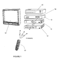
- the system generally includes one or more remote controls 10 each of which is adapted to transmit command codes to control the operation of one or more home appliances 12 as is illustrated in Fig. 1 .
- the appliances 12 can include, but are not limited to, televisions, VCRs, DVRs, DVD players, cable converter boxes, amplifiers, CD players, game consoles, home lighting, drapery, fans, HVAC systems, thermostats, personal computers, etc.
- the remote control 10 is described hereinafter in the context of a universal remote control, i.e., one that is modifiable to command appliances of different types of different manufactures, it is to be appreciated that the remote control 10 may also be a dedicated remote control, i.e., a remote control that is supplied by a manufacturer with an appliance that is preprogrammed to command that appliance. In certain other cases, the remote control 10 may also be a dedicated remote control (with respect to the type of appliance it was supplied with) and a universal remote control with.respect to other appliance types (e.g., a remote control that has its TV mode preset to the Sony brand television with which it was supplied while being universal with respect to other modes such as a VCR mode).
- a dedicated remote control i.e., a remote control that is supplied by a manufacturer with an appliance that is preprogrammed to command that appliance.
- the remote control 10 may also be a dedicated remote control (with respect to the type of appliance it was supplied with) and a universal remote control with.re
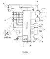
- the remote control 10 may include, as needed for a particular application, a processor 24 coupled to a ROM memory 26, a key matrix 28 (e.g., physical buttons, a touch screen display, or a combination thereof), an internal clock and timer 30, transmission circuit(s) 32, receiver circuit(s) 33 and/or transceiver circuit(s) (e.g., IR and/or RF), a non-volatile read/write memory 34, a means 36 to provide feedback to the user (e.g, LED, display, speaker, and/or the like), a power supply 38, and input means 39 (e.g., serial I/O port, wireless receiver, bar code scanner, etc.) as generally illustrated in Fig.
- a processor 24 coupled to a ROM memory 26, a key matrix 28 (e.g., physical buttons, a touch screen display, or a combination thereof), an internal clock and timer 30, transmission circuit(s) 32, receiver circuit(s) 33 and/or transceiver circuit(s) (e.g.,
- the ROM memory 26 may include executable instructions that are intended to be executed by the processor 24 to control the operation of the remote control 10.
- the processor 24 may be programmed to control the various electronic components within the remote control 10, e.g., to monitor the power supply 38, to cause the transmission of signals, etc.
- the non-volatile read/write memory 34 for example an EEPROM, battery-backed up RAM, Smart Card, memory stick, or the like, may be provided to store setup data and parameters as necessary. While the memory 26 is illustrated and described as a ROM memory, memory 26 can also be comprised of any type of readable media, such as ROM, RAM, SRAM, FLASH, EEPROM, or the like.
- the memory 26 is non-volatile or battery-backed such that data is not required to be reloaded after battery changes.
- the memories 26 and 34 may take the form of a chip, a hard disk, a magnetic disk, and/or an optical disk.
- the remote control 10 is adapted to be responsive to events, such as a sensed user interaction with the key matrix 28, receipt of a transmission, etc.
- appropriate instructions within the memory 26 may be executed.
- the remote control 10 may retrieve a command code corresponding to the activated command key from memory 26 and transmit the command code to a device in a format recognizable by the device.
- the instructions within the memory 26 can be used not only to cause the transmission of command codes and/or data to the appliances 12 but also to perform local operations. While not limiting, local operations that may be performed by the remote control 10 include displaying information/data, favorite channel setup, macro button setup, function key relocation, etc.
- the remote control 10 preferably includes programming such that activation of a macro key causes the transmission of a sequence of command codes that have been assigned to the macro key.
- the macro programming will also allow a user to assign one or more command codes to the macro key.
- the assignment of command codes to the macro key may be made by the user interacting with the keys of the remote control 10 in the manner described in U.S. Patent Nos. 5,959,751 or 6,587,067 .
- the remote control can be preprogrammed to transmit one or more command codes in response to activation of the macro key.
- one or more command codes may be assigned to the macro key by means of being downloaded to the remote control, for example after an interactive session with a network site that maintains a database of command codes.
- the subject system and method includes a command receiver 14.
- the command receiver 14 may be a device separate and apart from the appliances 12 or may be integrated into one or more of the appliances 12 as is illustrated in Fig. 1 .
- the command receiver 14 may include, as needed for a particular application, a processor 50 coupled to a ROM memory 52, an internal clock and timer 53, receiver circuit(s) 54, transmission circuit(s) 55 and/or transceiver circuit(s) (e.g., IR and/or RF), a non-volatile read/write memory 56, a means 58 to provide feedback to the user (e.g., LED, display, speaker, and/or the like), a power supply 62, and input means 64, (e.g., serial I/O port, wireless receiver, bar code scanner, etc.), as is generally illustrated in Fig. 3 .
- a processor 50 coupled to a ROM memory 52, an internal clock and timer 53, receiver circuit(s) 54, transmission circuit(s) 55 and/or transceiver circuit(s) (e.g., IR and/or RF), a non-volatile read/write memory 56, a means 58 to provide feedback to the user (e.g., LED,
- the ROM memory 52 includes executable instructions that are intended to be executed by the processor 50 to control the operation of the command receiver 14.
- the processor 50 may be programmed to control the various electronic components within the command receiver 14, e.g., to monitor the power supply 62, to cause the transmission of signals, to provide audio or visual prompts to a user, etc.
- the non-volatile read/write memory 56 for example an EEPROM, battery-backed up RAM, Smart Card, memory stick, or the like, is provided to store setup data and parameters as necessary. While the memory 52 is illustrated and described as a ROM memory, memory 52 can also be comprised of any type of readable media, such as ROM, RAM, SRAM, FLASH, EEPROM, or the like.
- the memory 56 is non-volatile or battery-backed such that data is not required to be reloaded after battery changes.
- the memories 52 and 56 may take the form of a chip, a hard disk, a magnetic disk, and/or an optical disk. It will also be appreciated that in cases where command receiver capability is integrated into an appliance, some or all of the functional elements described above in conjunction with Fig. 3 may be combined with similar elements already present in the appliance for other purposes.
- a state table which stores parameters representative of one or more states of one or more appliances. More specifically, as illustrated in Fig. 4 , the state table attempts to reflect the state of an appliance by storing parameters that are indicative of the transmission of commands to an appliance. For example, if the appliance is responsive to a "power" toggle command, the "power" field (PF) for that appliance may toggle between a "1,” being used to represent that the appliance power should be on, and "0,” being used to represent that the appliance power should be off.
- the state parameter may be simple Boolean value for states that are either "on” or "off” or may be binary values, for example, representative of a number of times a command has been transmitted to an appliance.
- the command receiver 14 may also be programmed to recognize if an appliance is to change states once a predetermined number of command transmissions to command a state have been achieved, e.g., a VCR or PVR resumes a "playing" state after the receipt of a third "FF" command, the first received "FF” command causing the appliance to fast forward at 2X speed and the second received "FF” command causing the appliance to fast forward at 4X speed.
- state table may be maintained either in part or entirely at a location physically separate from the receiver 14 (such as, for example, a personal computer located elsewhere in the home) and need only be accessible to the receiver 14 for state data storage and retrieval operations, as will be described in more detail later.
- the command receiver 14 may be provided with a means to set the parameters within the state table to a known value, i.e., a reset state, to thereby resynchronize the state table to the actual state of the appliance.
- a known value i.e., a reset state
- the user may be instructed fully reduce the volume, etc. (either manually or via a remote control transmission), place the appliance in an "off" state, and then issue a reset command to the command receiver 14 (either manually or via a remote control transmission) to cause the state table for that appliance to reflect the known, "off," no-volume condition.
- the state table need not be used to reflect all possible states of an appliance. In some circumstances, it may only be desirable to track states that may change should the appliance receive a command to enter a state the appliance is already within, e.g. the transmission of a "power” toggle command for the purpose of powering on an appliance that is already on, the transmission of a "FF" command to an appliance already in “FF” mode and having multiple "FF” speeds, etc.
- an appliance is responsive to discrete power commands (as opposed to a "power toggle” command that causes the appliance to toggle between a "power on” state and a “power off” state) it may not be necessary to track the power state for the appliance, i.e., the state of the appliance would not be inadvertently changed as a result of receiving a discrete "power on” command in the case where the appliance is already powered on.
- the appliance to be monitored is preferably identified to the command receiver 14 using one or more of the methods described hereinafter.
- the particular states to monitor may be preconfigured or user programmable without limitation. For example, once an appliance is identified to the command receiver 14, the command receiver 14 will be able to recognize command transmissions from a remote control 10 intended for that appliance and, as such, will be aware of the functional states of the appliance that are controllable by a remote control 10.
- the programming within the command receiver 14 preferably includes instructions for monitoring for the transmission of command codes by the remote control 10 and for determining, especially in the case of a macro where a plurality of commands are to be transmitted in sequence, if all of the command codes in the sequence were received by the command receiver 14.
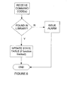
- a command code received by the receiver circuit(s) 54 may be compared against a library of command codes stored in the memory 52 or 56 of the command receiver 14. If command is properly received and recognized, the state table for the intended target appliance(s) may be updated to reflect the received command transmission. If the command is not properly received and recognized, an audible or visual alarm may be issued.
- the library of command codes which are used in the step of comparing may be stored in the memory 52 or 56 at the time of manufacture and/or be downloaded into the command receiver which, for example, allows the library of command codes to be upgradeable. Downloading may be performed by means of wired or wireless connection and may include downloading the command codes via a network connection as described in U.S.. Patent No. 4,959,810 , downloading the command codes via learning circuitry as described in U.S. Patent No. 4,623,887 , or the like.
- the command receiver 14 may additionally be programmed to recognize the sequence of command codes.
- the sequence of command codes that comprise a macro may be taught to the command receiver 14 in same manner as described in U.S. Patent No. 4,623,887 . More specifically, the command receiver 14 may be placed into a macro definition mode, the command codes that will comprise the macro may be transmitted to the command receiver 14 (for example, by the remote control 10), and the command receiver 14 may be caused to exit the macro definition mode as a means to inform the command receiver 14 that the entirety of the command sequence has been transmitted.
- sequence of command codes that will comprise a macro may also be programmed into the command receiver 14 by interacting with a keypad (not illustrated) of the command receiver 14 in the same manner that would be used to program the remote control 10 to transmit the macro. Still further, the sequence of command codes that will comprise a macro may be downloaded into the command receiver 14 via a network connection (for example if the remote control macro is set up via interaction with a Web site - the same macro can be downloaded into the command receiver 14), by means of being read from a barcode, by being read from a smart card, etc.
- the remote control 10 and command receiver 14 may be adapted to cooperate to facilitate the learning of command codes by the command receiver 14.
- the remote control 10 may be adapted to respond to a user input that functions to signify a desire to request registration of a macro with the command receiver 14.
- the remote control 10 may transmit a predefined "enter learning state" command to the command receiver 14 (e.g., using a standard infrared format recognizable by the command receiver 14) followed by the macro command code sequence to be taught to the command receiver 14.
- the end of the macro command code sequence may be signified by the remote control 10 transmitting an "exit learning state" command to the command receiver 14. It will be appreciated that the command receiver 14 should respond to the "exit learning state" command so as to stop the recording of transmissions from the remote control 10.
- the command receiver 14 is capable of comparing received command codes to determine if one or more received command codes has a counterpart within the library command codes accessible to the command receiver 14.
- the command receiver 14 may be programmed to always monitor the transmission of commands or may be programmed to commence the monitoring of command codes in response to a receipt of a "start monitoring" command code, for example, if selective monitoring is desired.
- the "start monitoring" command code may, for example, be transmitted from the remote control 10 as a prefix to a command code sequence that is transmitted from the remote control 10 in response to activation of a macro key.
- the command receiver 14 may issue an alarm, visible or audible, to inform the user that they should attempt to resend the command code.
- the sequence of command codes received by the receiver circuit(s) 54 of the command receiver 14 may also be compared against one or more stored sequences of command codes made accessible to the command receiver 14. In this manner, if a sequence of command codes received by the receiver circuit(s) 54 of the command receiver 14 fails to be found in the stored sequence(s) of command codes made accessible to the command receiver 14, e.g., one or more command codes are missing from the received transmission, the command receiver 14 may issue an alarm to inform the user that they should attempt to resend the macro command sequence.
- the command receiver 14 may also be desirable to have the command receiver 14 notify the remote control 10 as to which command codes from a macro command code sequence were not properly received by the command receiver 14 to thereby allow for the retransmission of just those command codes.
- the command receiver 14 may compare a received sequence of command codes against the macro command code sequences stored in memory, discern which macro stored in its memory is most likely to be the one that was intended to be transmitted by the remote control 10 (if more than one macro has been programmed into the command receiver 14), discern which command codes from that stored macro were not received, and issue a transmission (e.g., an event) to the remote control 10 that notifies the remote control 10 which commands were discerned to be missing from the intended macro transmission.
- a transmission e.g., an event
- the transmission from the command receiver 14 to the remote control 10 may include data indicative of the missing command codes, e.g., a pointer into the memory of the remote control 10, or the missing command codes themselves.
- the command codes may be temporarily stored in the memory of the remote control 10 for easy retransmission back to the appliances 12. In either instance, it is preferred that the user be provided with an indication, such as a visible or audio alarm, that the remote control 10 has received a transmission from the command receiver 14 and is in a state for retransmitting command codes to the appliances 12, either using the received data or received command codes.
- the retransmission from the remote control 10 may be initiated by using a key that has been provided for that purpose, by activating the macro key again (in which case the remote control 10 would temporarily override the original programming of that macro key), etc.
- the command receiver 14 may additionally be programmed to look for the successful retransmission of those command codes that were previously determined to be missing. An appropriate timeout may be utilized in such a case to prevent the command receiver from becoming locked in a state where it is looking for the specific transmission of such command codes.
- the system may also be configured such that the command receiver 14 is programmed to monitor the transmission of each command code as a sequence of command codes is received from the remote control 10. In this case, the command receiver 14 may confirm and acknowledge the receipt of that command code with the remote control 10. The remote control 10 may then wait for the acknowledgement before issuing the next command code in the sequence. If an acknowledgement is not received within a predetermined time, the remote control 10 may cause the command code from the sequence to be retransmitted.
- the command receiver 14 may be taught a macro label by, for example, having the "enter learning state" command include a designator, e.g. a number, which has been assigned to the macro command code sequence to be learned by the command receiver 14.
- the designator assigned to a macro command sequence and included in the "enter learning state” command may be user programmable or may be, for example, pre-programmed by being representative of a key of the remote control 10 to which the macro command code sequence has been assigned.
- the command receiver 14 may then be informed of which command code sequence it is expected to receive by, for example, including the macro designator as part of a "start monitoring" command code transmitted from the remote control 10.
- the command receiver 14 may also be desired, in the case where the command receiver 14 is integrated within an appliance 12, to perform further steps whereby the command receiver 14 also functions to discern if all of the command codes of a macro intended to be transmitted from the remote control 10 were intended for the appliance 12 having the command receiver 14. If all of the command codes of the macro were intended for the appliance 12 having the command receiver 14, the appliance 12 may include a further feature that prohibits the appliance 12 from acting upon the received command codes until such time as the command receiver 14 discerns that all of the command codes in a macro were correctly and completely received. Alternatively, the appliance 12 may be programmed to simply perform all of the operations indicated by the command codes in a macro despite the fact that certain commands were not received, for example if a predetermined number of commands from a programmed macro are received by the command receiver 14.
- the appliance 12 may consult a locally maintained state table or a general state table maintained by command receiver 14, or a remote device such as a personal computer, to discern if the appliance is already in a state desired by the macro and inhibit execution of a command that may effect that state, e.g., inhibit the execution of a "power toggle" command intended to turn the appliance on if the appliance is already in the "on" state.
- the appliance 12 may be preprogrammed to assume that the transmission of a "power toggle" command as part of a macro sequence is intended to turn an appliance "on.”
- the appliance 12 may also be manually programmable whereby a user can affirmatively inform the appliance as to which states the appliance is to achieve when a macro is executed, for example, using a menu or the like conventional programming tool.
- the system may also be adapted to query the state table before actually transmitting the commands associated with the macro.
- a macro command key i.e., a key that is to be actuated to commence transmission of a macro command sequence
- the remote control 10 may query the command receiver 14 to gather data indicative of the present state of the appliances.
- the remote control 10 may make a general request and upload data for all of the appliances being monitored by the command receiver 14 or may specify in the query message the appliances of interest, i.e., by examining the intended target appliances of the commands within the macro command sequence.
- the remote control 10 may examine the macro command sequence to discern the functions to be commanded and then issue a query with respect to only those functions of interest.
- the query may be further limited to only those functions that have the possibility of being acted upon to place an appliance in an unintended state, e.g., when the macro is intended to turn an appliance "on” and the appliance is known to be responsive to power toggle commands, which scenario is described in commonly assigned U.S. Application No. 10/087,078 which is incorporated herein by reference in its entirety.
- the command receiver 14 will examine its state table(s) and return the requested data to the remote control 10.
- the query/response communications between the remote control 10 and the command receiver 14 may be performed using an IR protocol such as XMP (described in co-pending U.S. Patent application 10/431,930 ) an RF protocol such as Bluetooth or 802.11, or any other suitable wireless transmission method. All that is required is that the command receiver 14 be able to decipher a received query command and that the remote control 10 be able to decipher a received query response. Once the remote control 10 receives the query response, the remote control 10 may intelligently utilize the state information to discern whether a command within a macro command sequence is to be transmitted.
- an IR protocol such as XMP (described in co-pending U.S. Patent application 10/431,930 )
- an RF protocol such as Bluetooth or 802.11, or any other suitable wireless transmission method. All that is required is that the command receiver 14 be able to decipher a received query command and that the remote control 10 be able to decipher a received query response.
- the remote control 10 may intelligent
- the remote control 10 may omit the transmission of the appliance power command from the sequence.
- the remote control 10 may be preprogrammed to assume that certain commands that are capable of commanding an appliance to enter into more than one state when received multiple time, e.g., a power toggle command, are intended to place the appliance in a specific state as part of the macro.
- a user may be provided with an opportunity to program the remote control 10 (using a conventional graphical user interface) or have the remote control 10 programmed (for example as part of a macro command downloading process) to indicate the exact state that an appliance is to enter in response to the receipt of a command in a macro sequence, e.g., that the appliance is to turn off when the macro is executed.
- the intended state of an appliance information would be stored within the memory of the remote control and be accessible as being associated with the macro.
- the state table of the command receiver 14 may also be queried to show a graphical representation of a state of a device (in cases where a remote control 10 has a graphical user interface display or is otherwise alterable to display appliance state information - for example, in the case of a remote control having an EL display).
- the command receiver 14 may be polled periodically.
- the command receiver 14 may issue a broadcast message to the remote control(s) 10 including data reflective of one or more state table(s) anytime the command receiver 14 causes a state table entry to be updated.
- the broadcast message may include data with respect to all of the entries of all of the state tables, data with respect to only the appliance whose state has changed, or data with respect to only the changed state.
- the received state information would again be stored within the remote control 10 and be accessed as needed to display state information to the user.
- the command receiver 14 may not be required to completely decode and understand command codes that it receives. Rather, the command receiver 14 may only need to store a representation of a command transmission that would be sufficient to identify if that same transmission has been sent by the remote control 10. Accordingly, differences in receiver bandwidth, response time, sampling interval, etc., between the command receiver hardware 54 and that of the other appliances for which signals are destined may not be critical provided the detected and stored signal data is consistent and repeatable, i.e., the stored representation need not be an exact representation of the transmitted command code sequence.
- the remote control 10 of the present invention may be any portable control device (including but not limited to IR and/or RF based remotes, portable phones, wireless capable PDAs, etc) capable of transmitting and/or receiving command codes remotely to and from the command receiver 14.
- the command receiver 14 of the present invention may be any home control device (including but not limited to STB's, media center PC's, home automation systems, etc) capable of receiving signals representing command codes from the portable control device, determining whether the complete set of command codes was received, and effectuating state changes in one or more appliances (either directly, or through further operation and interaction with the portable control device or other control devices).
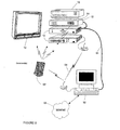
- a home control device such as a personal computer 92
- the home control device 92 may comprise machine-readable instructions loaded in an accessible memory such as a hard disk drive or other non-volatile memory.
- the command receiver 14 may be incorporated into the home control device 92 or may be located separately, communicating with the home control device via a wired (as illustrated in Figure 9 ) or wireless link.
- the machine-readable instructions of the home control device 92 may be adapted to perform pre-programmed logic processing on an incoming command code set(s) such that an accurate determination of the completeness of the received command codes may be made without pre-configuring, learning, or otherwise notifying the home control device of the incoming command codes sets prior to receiving the command codes.
- the software to implement such a system is well within the routine skill of a programmer, and may include for instance, reference to a comparative database of command codes types, frequently used or desirable command code sets, determination of a particular command code scheme (such as a particular type of IR command encoding scheme), etc.
- a combination of learned, programmed, or pre-loaded command codes sets used in conjunction with software based logic operations in the home control device may serve to further enhance the accuracy of determined missing command codes, while not necessarily requiring a user to program or teach every desired command code set to the home control device.
- the home control device may also be connected to a network (such as a wired LAN or Firewire link 94, a wireless LAN 96, a WAN, or the Internet 98) such that it may receive close range command codes (such as via an IR or RF based remote control 10') and/or long range command codes (such as from a remote user sending command codes from a portable phone, wireless enabled PDA, etc via the Internet), in each case the home control device 92 being able to determine whether a complete set of command codes was received, and initiate a corrective measure via a signal back to the user and/or portable control device, or directly to the appliance(s) affected by the missing or incomplete command codes.
- a network such as a wired LAN or Firewire link 94, a wireless LAN 96, a WAN, or the Internet 98
- close range command codes such as via an IR or RF based remote control 10'
- long range command codes such as from a remote user sending command codes from a portable phone, wireless enabled
- a remote user may send command codes (for instance representing commands to turn on the house lights and the home stereo) from a user interface on a wireless enabled PDA via the Internet to the home control device.
- the command codes may be any digital representation of the actual command codes to be sent the desired appliances, including a reference name or number indicating to the home control device the desired command codes.
- the home control device may then determine whether all command codes of the command code set were received properly (using the system and method as described above) and generate a signal to correct any missing or incomplete command codes.
- the home control device may generate a signal to notify the portable control device and/or user to resend the command codes (either the entire command code set, selected missing command codes, or command codes for the portable control device to repeat back directly to one or more appliances).
- the home control device may also consult the state table to prevent an appliance from being placed into an unintended state by a command received from a remote device, such as a PDA.
- the home control device may serve to relay desired command codes directly to various desired appliances to effectuate the desired functionality, or may relay one or more signals to a secondary signal relay/generation device (such as an IR repeater, RF wireless access point, etc) to effectuate the desired appliance functionality.
- a secondary signal relay/generation device such as an IR repeater, RF wireless access point, etc
- Such a system may also be used to relay state information to a remote device, such as a PDA, whereby the user may discern the present state of an appliance, i.e., have the children turned on the TV, did the user forget to turn off an appliance, etc.
- the remote device may again be used to initiate the transmission of a command to an appliance to perform an action, either automatically or manually, in the case where the desired state of an appliance does not match that reported to the remote device.
- the home control device 92 may additionally communicate directly with such appliances in order to determine the current status of various states. As before, the status of various states of various appliances can be returned to the remote control 10' for consideration during the command transmission process. While various concepts have been described in detail, it will be appreciated by those skilled in the art that various modifications and alternatives to those concepts could be developed in light of the overall teachings of the disclosure.
Applications Claiming Priority (3)
| Application Number | Priority Date | Filing Date | Title |
|---|---|---|---|
| US10/603,839 US7005979B2 (en) | 2003-06-25 | 2003-06-25 | System and method for monitoring remote control transmissions |
| US10/665,650 US7126468B2 (en) | 2003-06-25 | 2003-09-19 | System and method for monitoring remote control transmissions |
| EP04755673A EP1644904B1 (de) | 2003-06-25 | 2004-06-16 | System und verfahen zur überwachung von fernbedienungs-übertragungen |
Related Parent Applications (1)
| Application Number | Title | Priority Date | Filing Date |
|---|---|---|---|
| EP04755673.3 Division | 2004-06-16 |
Publications (3)
| Publication Number | Publication Date |
|---|---|
| EP2154661A2 true EP2154661A2 (de) | 2010-02-17 |
| EP2154661A3 EP2154661A3 (de) | 2010-05-05 |
| EP2154661B1 EP2154661B1 (de) | 2011-03-16 |
Family
ID=33539811
Family Applications (3)
| Application Number | Title | Priority Date | Filing Date |
|---|---|---|---|
| EP08157064.0A Active EP1965363B1 (de) | 2003-06-25 | 2004-06-16 | System und Verfahren zur Überwachung der Übertragungsfernbedienung |
| EP11169750.4A Active EP2367160B1 (de) | 2003-06-25 | 2004-06-16 | System und verfahren zur überwachung der übertragungsfernbedienung |
| EP09175061A Active EP2154661B1 (de) | 2003-06-25 | 2004-06-16 | System und Verfahren zur Überwachung von Fernsteuerungsübertragungen |
Family Applications Before (2)
| Application Number | Title | Priority Date | Filing Date |
|---|---|---|---|
| EP08157064.0A Active EP1965363B1 (de) | 2003-06-25 | 2004-06-16 | System und Verfahren zur Überwachung der Übertragungsfernbedienung |
| EP11169750.4A Active EP2367160B1 (de) | 2003-06-25 | 2004-06-16 | System und verfahren zur überwachung der übertragungsfernbedienung |
Country Status (4)
| Country | Link |
|---|---|
| US (2) | US7005979B2 (de) |
| EP (3) | EP1965363B1 (de) |
| AT (2) | ATE451675T1 (de) |
| DE (2) | DE602004031896D1 (de) |
Cited By (1)
| Publication number | Priority date | Publication date | Assignee | Title |
|---|---|---|---|---|
| TWI747520B (zh) * | 2019-10-03 | 2021-11-21 | 蔡牧辰 | 多功能遙控器 |
Families Citing this family (110)
| Publication number | Priority date | Publication date | Assignee | Title |
|---|---|---|---|---|
| US8531276B2 (en) | 2000-03-15 | 2013-09-10 | Logitech Europe S.A. | State-based remote control system |
| US7283059B2 (en) * | 2000-03-15 | 2007-10-16 | Logitech Europe S.A. | Remote control multimedia content listing system |
| US20010033243A1 (en) * | 2000-03-15 | 2001-10-25 | Harris Glen Mclean | Online remote control configuration system |
| US6784805B2 (en) | 2000-03-15 | 2004-08-31 | Intrigue Technologies Inc. | State-based remote control system |
| US7194259B2 (en) * | 2003-09-05 | 2007-03-20 | Sony Ericsson Mobile Communications Ab | Remote control device having wireless phone interface |
| US9754480B2 (en) | 2003-11-04 | 2017-09-05 | Universal Electronics Inc. | System and method for controlling device location determination |
| US7136709B2 (en) | 2003-11-04 | 2006-11-14 | Universal Electronics Inc. | Home appliance control system and methods in a networked environment |
| US7363028B2 (en) | 2003-11-04 | 2008-04-22 | Universal Electronics, Inc. | System and method for controlling device location determination |
| KR100606060B1 (ko) | 2004-02-21 | 2006-07-26 | 삼성전자주식회사 | 휴대단말기의 데이터를 외부장치로 출력하는 장치 및 방법 |
| US7116229B1 (en) * | 2004-03-31 | 2006-10-03 | Zilog, Inc. | Programming a remote control device using RFID technology |
| JP4095591B2 (ja) * | 2004-08-04 | 2008-06-04 | キヤノン株式会社 | ユーザインタフェース装置、処理装置、ユーザインタフェース方法、プログラムおよび記憶媒体 |
| US20060126447A1 (en) * | 2004-10-12 | 2006-06-15 | Warner Bros. Entertainment Inc. | Remote control system for an optical disc player and related method |
| US20060087595A1 (en) * | 2004-10-26 | 2006-04-27 | Lg Electronics Inc. | System and method for interfacing remote controller with digital broadcasting receiver |
| US7319394B2 (en) * | 2004-10-26 | 2008-01-15 | Intel Corporation | Techniques to configure a remote control |
| KR20060046333A (ko) * | 2004-11-03 | 2006-05-17 | 엘지전자 주식회사 | 데이터 방송 정보 데이터 구조, 데이터 방송 구분 방법그리고, 데이터 방송 송수신 시스템 |
| KR100630202B1 (ko) * | 2004-11-11 | 2006-09-29 | 삼성전자주식회사 | Sim 어플리케이션 툴킷을 이용한 사용자 단말기의 서브디바이스 제어 방법 |
| US6990335B1 (en) * | 2004-11-18 | 2006-01-24 | Charles G. Shamoon | Ubiquitous connectivity and control system for remote locations |
| JP4207900B2 (ja) | 2004-12-22 | 2009-01-14 | ソニー株式会社 | リモコン・システム、リモート・コマンダ、並びにリモコン・サーバ |
| KR101263668B1 (ko) * | 2005-03-08 | 2013-05-21 | 코닌클리케 필립스 일렉트로닉스 엔.브이. | 프로그램 동작을 변경하기 위해 태그들을 이용하는 방법 |
| US20070038787A1 (en) * | 2005-03-30 | 2007-02-15 | Logitech Europe S.A. | Interface device and method for networking legacy consumer electronics devices |
| DE102006018238A1 (de) | 2005-04-20 | 2007-03-29 | Logitech Europe S.A. | System und Verfahren zur adaptiven Programmierung einer Fernbedienung |
| JP2006338748A (ja) * | 2005-05-31 | 2006-12-14 | Orion Denki Kk | 操作対象案内機能を備えた複合電子装置 |
| JP2007036906A (ja) * | 2005-07-29 | 2007-02-08 | Victor Co Of Japan Ltd | 電子機器システム |
| US8880047B2 (en) * | 2005-08-03 | 2014-11-04 | Jeffrey C. Konicek | Realtime, location-based cell phone enhancements, uses, and applications |
| US8295851B2 (en) | 2005-08-03 | 2012-10-23 | Michael Edward Finnegan | Realtime, interactive and geographically defined computerized personal matching systems and methods |
| US20070233731A1 (en) * | 2006-02-22 | 2007-10-04 | Logitech Europe S.A. | System and method for configuring media systems |
| DE602006015051D1 (de) | 2006-09-04 | 2010-08-05 | Honeywell Technologies Sarl | Verbessertes Bedienfeld |
| US8812629B2 (en) | 2008-04-18 | 2014-08-19 | Universal Electronics Inc. | System and method for configuring the remote control functionality of a portable device |
| US9208679B2 (en) | 2006-09-05 | 2015-12-08 | Universal Electronics Inc. | System and method for configuring the remote control functionality of a portable device |
| US8659400B2 (en) | 2006-09-05 | 2014-02-25 | Universal Electronics Inc. | System and method for configuring the remote control functionality of a portable device |
| US8077263B2 (en) | 2006-10-23 | 2011-12-13 | Sony Corporation | Decoding multiple remote control code sets |
| US20080098357A1 (en) * | 2006-10-23 | 2008-04-24 | Candelore Brant L | Phantom information commands |
| US20080154806A1 (en) * | 2006-12-22 | 2008-06-26 | Morris Robert P | Methods, systems, and computer program products for a self-automating set of services or devices |
| US8310337B2 (en) * | 2007-01-05 | 2012-11-13 | Monster Cable Products, Inc. | State sensing for a remote control |
| KR101504115B1 (ko) * | 2007-03-12 | 2015-03-19 | 삼성전자 주식회사 | 매크로 명령 동작 장치와 매크로 명령 입력 장치 및 방법 |
| US8438589B2 (en) | 2007-03-28 | 2013-05-07 | Sony Corporation | Obtaining metadata program information during channel changes |
| US20090053997A1 (en) * | 2007-08-24 | 2009-02-26 | Motorola, Inc. | Dynamic user interface for displaying connection status and method thereof |
| US20090102617A1 (en) * | 2007-10-22 | 2009-04-23 | Douglas Thommes | Method, system and computer program product for controlling a plurality of devices in an environment |
| US8552843B2 (en) * | 2008-02-12 | 2013-10-08 | Smk Manufacturing | Universal remote controller having home automation function |
| US9088663B2 (en) | 2008-04-18 | 2015-07-21 | Universal Electronics Inc. | System for appliance control via a network |
| CN102047156B (zh) * | 2008-05-30 | 2014-03-26 | 皇家飞利浦电子股份有限公司 | 圆弧形照明设备 |
| US20100050270A1 (en) * | 2008-08-20 | 2010-02-25 | AT&T InteIlectual Property I, L.P. | Control of Access to Content Received from a Multimedia Content Distribution Network |
| JP2010161588A (ja) * | 2009-01-07 | 2010-07-22 | Yamaha Corp | 遠隔制御システム |
| EP2428000B1 (de) * | 2009-05-07 | 2012-08-29 | Koninklijke Philips Electronics N.V. | Verfahren zum steuern von sendungen von einer ressourcenbeschränkten einrichtung und batterielose einrichtung |
| US9405710B2 (en) * | 2009-06-30 | 2016-08-02 | Rovi Guides, Inc. | Systems and methods for providing interactive media guidance on a wireless communications device |
| KR101642111B1 (ko) | 2009-08-18 | 2016-07-22 | 삼성전자주식회사 | 방송수신장치, 모바일 디바이스, 서비스 제공 방법 및 방송수신장치 제어 방법 |
| US9251702B2 (en) * | 2009-08-25 | 2016-02-02 | Koninklijke Philips N.V. | Remote control of a plurality of devices |
| GB2474508B (en) * | 2009-10-16 | 2015-12-09 | Norwell Sa | Audience measurement system |
| US8299954B2 (en) | 2009-12-15 | 2012-10-30 | At&T Intellectual Property I, L.P. | Proxy remote control |
| US8316413B2 (en) | 2010-02-04 | 2012-11-20 | Eldon Technology Limited | Apparatus for displaying electrical device usage information on a television receiver |
| US9599981B2 (en) * | 2010-02-04 | 2017-03-21 | Echostar Uk Holdings Limited | Electronic appliance status notification via a home entertainment system |
| US8458748B2 (en) * | 2010-04-20 | 2013-06-04 | Time Warner Cable, Inc. | System and method for commanding a controlled device |
| US9310887B2 (en) * | 2010-05-06 | 2016-04-12 | James W. Wieder | Handheld and wearable remote-controllers |
| JP2011244287A (ja) * | 2010-05-19 | 2011-12-01 | Sony Corp | 情報処理装置及び情報処理方法 |
| US9786159B2 (en) | 2010-07-23 | 2017-10-10 | Tivo Solutions Inc. | Multi-function remote control device |
| US8508401B1 (en) | 2010-08-31 | 2013-08-13 | Logitech Europe S.A. | Delay fixing for command codes in a remote control system |
| US20120105195A1 (en) * | 2010-10-29 | 2012-05-03 | Johnson Controls Technology Company | Wireless transceiver with recall indicator |
| US10303357B2 (en) | 2010-11-19 | 2019-05-28 | TIVO SOLUTIONS lNC. | Flick to send or display content |
| US8918719B2 (en) * | 2011-02-14 | 2014-12-23 | Universal Electronics Inc. | Graphical user interface and data transfer methods in a controlling device |
| FR2972062B1 (fr) * | 2011-02-28 | 2013-04-12 | Somfy Sas | Dispositif de commande comprenant une interface capable de proposer le prochain ordre de commande a transmettre a un equipement domotique |
| KR20120099857A (ko) * | 2011-03-02 | 2012-09-12 | 삼성전자주식회사 | 통합 리모콘 시스템 및 그 제어 방법 |
| US20140376919A1 (en) * | 2011-03-24 | 2014-12-25 | Robert P. Stratton | Remote Control System and Method |
| US8918544B2 (en) | 2011-03-31 | 2014-12-23 | Logitech Europe S.A. | Apparatus and method for configuration and operation of a remote-control system |
| US8745024B2 (en) | 2011-04-29 | 2014-06-03 | Logitech Europe S.A. | Techniques for enhancing content |
| CN110677330A (zh) * | 2011-12-21 | 2020-01-10 | 英特尔公司 | 用于促进计算设备和非计算设备的基于代理用户界面的远程管理和控制的机制 |
| KR101634745B1 (ko) | 2011-12-30 | 2016-06-30 | 삼성전자 주식회사 | 전자장치, 이를 제어할 수 있는 사용자 입력장치 및 그 제어방법 |
| EP2667268A1 (de) * | 2012-05-24 | 2013-11-27 | Siemens Aktiengesellschaft | Verfahren zum Betrieb eines Automatisierungsgeräts |
| US20140029913A1 (en) * | 2012-07-30 | 2014-01-30 | General Instrument Corporation | Controlling Trick Play And Progress of Media Playback For Multiple Media Devices |
| US9478123B2 (en) * | 2012-07-31 | 2016-10-25 | Intellectual Discovery Co., Ltd. | Remote control device and method |
| US9640067B1 (en) * | 2012-09-04 | 2017-05-02 | Amazon Technologies, Inc. | Determining commands on a media device interface |
| US9437106B2 (en) * | 2012-10-01 | 2016-09-06 | Logitech Europe S.A. | Techniques for controlling appliances |
| US9952576B2 (en) * | 2012-10-16 | 2018-04-24 | Sonos, Inc. | Methods and apparatus to learn and share remote commands |
| TW201417058A (zh) * | 2012-10-25 | 2014-05-01 | Hon Hai Prec Ind Co Ltd | 電子裝置、移動控制裝置及控制方法 |
| KR101942839B1 (ko) | 2012-10-31 | 2019-01-29 | 삼성전자주식회사 | 에이전트 장치, 전기기기 및 그의 제어 방법 |
| US9009458B2 (en) * | 2013-03-14 | 2015-04-14 | Google Inc. | Systems, methods, and media for managing an entertainment system |
| JP6167660B2 (ja) * | 2013-05-13 | 2017-07-26 | 住友電気工業株式会社 | リモートコントローラおよびリモートコントロールシステム |
| CN105247876A (zh) | 2013-05-20 | 2016-01-13 | 汤姆逊许可公司 | 使用图像编程的远程控制器 |
| JP6300001B2 (ja) * | 2013-09-20 | 2018-03-28 | 東芝ライテック株式会社 | 家電機器、コントローラ及び通信アダプタ |
| WO2015073107A1 (en) * | 2013-11-12 | 2015-05-21 | UTC Fire & Security Americas Corporation, Inc | Mobile user interface for security panel |
| EP3069453B1 (de) | 2013-11-15 | 2021-07-14 | Gentex Corporation | Mit dem internet verbundenes garagentorsteuerungssystem |
| US20150163411A1 (en) | 2013-12-11 | 2015-06-11 | Echostar Technologies, Llc | Home Monitoring and Control |
| US9900177B2 (en) | 2013-12-11 | 2018-02-20 | Echostar Technologies International Corporation | Maintaining up-to-date home automation models |
| US9495860B2 (en) | 2013-12-11 | 2016-11-15 | Echostar Technologies L.L.C. | False alarm identification |
| US9769522B2 (en) | 2013-12-16 | 2017-09-19 | Echostar Technologies L.L.C. | Methods and systems for location specific operations |
| US9723393B2 (en) | 2014-03-28 | 2017-08-01 | Echostar Technologies L.L.C. | Methods to conserve remote batteries |
| US9621959B2 (en) | 2014-08-27 | 2017-04-11 | Echostar Uk Holdings Limited | In-residence track and alert |
| US9824578B2 (en) | 2014-09-03 | 2017-11-21 | Echostar Technologies International Corporation | Home automation control using context sensitive menus |
| US9989507B2 (en) | 2014-09-25 | 2018-06-05 | Echostar Technologies International Corporation | Detection and prevention of toxic gas |
| US9983011B2 (en) | 2014-10-30 | 2018-05-29 | Echostar Technologies International Corporation | Mapping and facilitating evacuation routes in emergency situations |
| US9511259B2 (en) | 2014-10-30 | 2016-12-06 | Echostar Uk Holdings Limited | Fitness overlay and incorporation for home automation system |
| US9967614B2 (en) | 2014-12-29 | 2018-05-08 | Echostar Technologies International Corporation | Alert suspension for home automation system |
| US9729989B2 (en) | 2015-03-27 | 2017-08-08 | Echostar Technologies L.L.C. | Home automation sound detection and positioning |
| US9948477B2 (en) | 2015-05-12 | 2018-04-17 | Echostar Technologies International Corporation | Home automation weather detection |
| US9946857B2 (en) | 2015-05-12 | 2018-04-17 | Echostar Technologies International Corporation | Restricted access for home automation system |
| US9632746B2 (en) | 2015-05-18 | 2017-04-25 | Echostar Technologies L.L.C. | Automatic muting |
| US9960980B2 (en) | 2015-08-21 | 2018-05-01 | Echostar Technologies International Corporation | Location monitor and device cloning |
| US9996066B2 (en) | 2015-11-25 | 2018-06-12 | Echostar Technologies International Corporation | System and method for HVAC health monitoring using a television receiver |
| US10101717B2 (en) | 2015-12-15 | 2018-10-16 | Echostar Technologies International Corporation | Home automation data storage system and methods |
| US9798309B2 (en) | 2015-12-18 | 2017-10-24 | Echostar Technologies International Corporation | Home automation control based on individual profiling using audio sensor data |
| US10091017B2 (en) | 2015-12-30 | 2018-10-02 | Echostar Technologies International Corporation | Personalized home automation control based on individualized profiling |
| US10060644B2 (en) | 2015-12-31 | 2018-08-28 | Echostar Technologies International Corporation | Methods and systems for control of home automation activity based on user preferences |
| US10073428B2 (en) | 2015-12-31 | 2018-09-11 | Echostar Technologies International Corporation | Methods and systems for control of home automation activity based on user characteristics |
| US9628286B1 (en) | 2016-02-23 | 2017-04-18 | Echostar Technologies L.L.C. | Television receiver and home automation system and methods to associate data with nearby people |
| US9882736B2 (en) | 2016-06-09 | 2018-01-30 | Echostar Technologies International Corporation | Remote sound generation for a home automation system |
| US10294600B2 (en) | 2016-08-05 | 2019-05-21 | Echostar Technologies International Corporation | Remote detection of washer/dryer operation/fault condition |
| US10049515B2 (en) | 2016-08-24 | 2018-08-14 | Echostar Technologies International Corporation | Trusted user identification and management for home automation systems |
| US20190134247A1 (en) * | 2017-11-07 | 2019-05-09 | Kingsley Oligie | Fan with air freshening dispenser |
| CN108958112B (zh) * | 2018-06-29 | 2021-04-23 | 广州市得腾技术服务有限责任公司 | 一种智能家居匹配器 |
| US11449250B2 (en) | 2019-10-14 | 2022-09-20 | Micron Technology, Inc. | Managing a mode to access a memory component or a logic component for machine learning computation in a memory sub-system |
| CN114768242A (zh) * | 2022-04-07 | 2022-07-22 | 武狄实业(上海)有限公司 | 一种电竞娱乐系统 |
Citations (9)
| Publication number | Priority date | Publication date | Assignee | Title |
|---|---|---|---|---|
| US4623887A (en) | 1984-05-15 | 1986-11-18 | General Electric Company | Reconfigurable remote control |
| US4959810A (en) | 1987-10-14 | 1990-09-25 | Universal Electronics, Inc. | Universal remote control device |
| US5235414A (en) | 1990-05-21 | 1993-08-10 | Control Data Corporation | Non-obtrusive programming monitor |
| US5481256A (en) | 1987-10-14 | 1996-01-02 | Universal Electronics Inc. | Direct entry remote control with channel scan |
| US5614906A (en) | 1996-04-23 | 1997-03-25 | Universal Electronics Inc. | Method for selecting a remote control command set |
| US6014092A (en) | 1987-10-14 | 2000-01-11 | Universal Electronics Inc. | Key mover |
| US6225938B1 (en) | 1999-01-14 | 2001-05-01 | Universal Electronics Inc. | Universal remote control system with bar code setup |
| US20010045819A1 (en) | 2000-03-15 | 2001-11-29 | Harris Glen Mclean | State-based remote control system |
| US8707802B2 (en) | 2010-10-22 | 2014-04-29 | Seiko Epson Corporation | Detection device, electronic apparatus, and robot |
Family Cites Families (20)
| Publication number | Priority date | Publication date | Assignee | Title |
|---|---|---|---|---|
| US264767A (en) | 1882-09-19 | Anatole exupere equip | ||
| DE3508562A1 (de) * | 1985-03-11 | 1986-09-11 | Philips Patentverwaltung Gmbh, 2000 Hamburg | Verfahren und anordnung zur uebertragung von informationen |
| US4703359A (en) * | 1985-05-30 | 1987-10-27 | Nap Consumer Electronics Corp. | Universal remote control unit with model identification capability |
| JPH0374139A (ja) * | 1989-05-16 | 1991-03-28 | Sony Corp | 電源状態検出装置 |
| US5410326A (en) * | 1992-12-04 | 1995-04-25 | Goldstein; Steven W. | Programmable remote control device for interacting with a plurality of remotely controlled devices |
| EP0784837B1 (de) * | 1995-07-05 | 2001-11-07 | Koninklijke Philips Electronics N.V. | Übertragungssystem zwischen einer dynamischen gruppe von vorrichtungen |
| US5787259A (en) * | 1996-03-29 | 1998-07-28 | Microsoft Corporation | Digital interconnects of a PC with consumer electronics devices |
| US6223348B1 (en) * | 1997-09-03 | 2001-04-24 | Universal Electronics Inc. | Universal remote control system |
| US6747568B1 (en) * | 1997-12-19 | 2004-06-08 | Thomson Licensing S.A. | Remote control code search method and apparatus |
| US20020140571A1 (en) * | 2001-01-29 | 2002-10-03 | Hayes Patrick H. | System and method for using a hand held device to display product information |
| JP2000184478A (ja) * | 1998-12-16 | 2000-06-30 | Sharp Corp | リモコン装置、被制御装置、リモコンシステム、及びリモコンシステムの制御方法 |
| US6496927B1 (en) * | 1999-06-09 | 2002-12-17 | Amx Corporation | Method and configuring a user interface for controlling a controlled device based upon a device class |
| US6725281B1 (en) * | 1999-06-11 | 2004-04-20 | Microsoft Corporation | Synchronization of controlled device state using state table and eventing in data-driven remote device control model |
| FR2809839A1 (fr) * | 1999-12-30 | 2001-12-07 | Thomson Multimedia Sa | Procede de telechargement de donnees procedees par des signaux d'annonce |
| US6956496B1 (en) * | 2000-01-18 | 2005-10-18 | Zilog, Inc. | Method and apparatus for updating universal remote databases through TV VBI processing |
| US7102688B2 (en) | 2001-01-29 | 2006-09-05 | Universal Electronics Inc. | System and method for using a hand held device to display a readable representation of an audio track |
| US6938101B2 (en) | 2001-01-29 | 2005-08-30 | Universal Electronics Inc. | Hand held device having a browser application |
| US6763491B2 (en) * | 2001-02-07 | 2004-07-13 | Telefonaktiebolaget Lm Ericsson (Publ) | Methods and systems for avoiding unnecessary retransmissions associated with automatic retransmission query schemes in radiocommunication systems |
| US6642852B2 (en) | 2002-03-01 | 2003-11-04 | Universal Electronics Inc. | Remote control device with appliance power awareness |
| US7167913B2 (en) | 2002-06-05 | 2007-01-23 | Universal Electronics Inc. | System and method for managing communication links |
-
2003
- 2003-06-25 US US10/603,839 patent/US7005979B2/en not_active Expired - Lifetime
- 2003-09-19 US US10/665,650 patent/US7126468B2/en active Active
-
2004
- 2004-06-16 AT AT04755673T patent/ATE451675T1/de not_active IP Right Cessation
- 2004-06-16 EP EP08157064.0A patent/EP1965363B1/de active Active
- 2004-06-16 DE DE602004031896T patent/DE602004031896D1/de active Active
- 2004-06-16 AT AT09175061T patent/ATE502369T1/de not_active IP Right Cessation
- 2004-06-16 EP EP11169750.4A patent/EP2367160B1/de active Active
- 2004-06-16 DE DE602004024535T patent/DE602004024535D1/de active Active
- 2004-06-16 EP EP09175061A patent/EP2154661B1/de active Active
Patent Citations (11)
| Publication number | Priority date | Publication date | Assignee | Title |
|---|---|---|---|---|
| US4623887A (en) | 1984-05-15 | 1986-11-18 | General Electric Company | Reconfigurable remote control |
| US4959810A (en) | 1987-10-14 | 1990-09-25 | Universal Electronics, Inc. | Universal remote control device |
| US5481256A (en) | 1987-10-14 | 1996-01-02 | Universal Electronics Inc. | Direct entry remote control with channel scan |
| US5959751A (en) | 1987-10-14 | 1999-09-28 | Universal Electronics Inc. | Universal remote control device |
| US6014092A (en) | 1987-10-14 | 2000-01-11 | Universal Electronics Inc. | Key mover |
| US6587067B2 (en) | 1987-10-14 | 2003-07-01 | Universal Electronics Inc. | Universal remote control with macro command capabilities |
| US5235414A (en) | 1990-05-21 | 1993-08-10 | Control Data Corporation | Non-obtrusive programming monitor |
| US5614906A (en) | 1996-04-23 | 1997-03-25 | Universal Electronics Inc. | Method for selecting a remote control command set |
| US6225938B1 (en) | 1999-01-14 | 2001-05-01 | Universal Electronics Inc. | Universal remote control system with bar code setup |
| US20010045819A1 (en) | 2000-03-15 | 2001-11-29 | Harris Glen Mclean | State-based remote control system |
| US8707802B2 (en) | 2010-10-22 | 2014-04-29 | Seiko Epson Corporation | Detection device, electronic apparatus, and robot |
Cited By (1)
| Publication number | Priority date | Publication date | Assignee | Title |
|---|---|---|---|---|
| TWI747520B (zh) * | 2019-10-03 | 2021-11-21 | 蔡牧辰 | 多功能遙控器 |
Also Published As
| Publication number | Publication date |
|---|---|
| ATE451675T1 (de) | 2009-12-15 |
| US7005979B2 (en) | 2006-02-28 |
| EP2154661A3 (de) | 2010-05-05 |
| EP1965363A2 (de) | 2008-09-03 |
| DE602004024535D1 (de) | 2010-01-21 |
| EP2367160A1 (de) | 2011-09-21 |
| EP1965363A3 (de) | 2008-09-17 |
| US20040266419A1 (en) | 2004-12-30 |
| EP1965363B1 (de) | 2017-08-30 |
| ATE502369T1 (de) | 2011-04-15 |
| US7126468B2 (en) | 2006-10-24 |
| DE602004031896D1 (de) | 2011-04-28 |
| EP2154661B1 (de) | 2011-03-16 |
| EP2367160B1 (de) | 2017-08-09 |
| US20040263349A1 (en) | 2004-12-30 |
Similar Documents
| Publication | Publication Date | Title |
|---|---|---|
| EP2367160B1 (de) | System und verfahren zur überwachung der übertragungsfernbedienung | |
| US9613526B2 (en) | System and method for controlling device location determination | |
| EP3330939B1 (de) | Medienrenderingsystem | |
| JP4566997B2 (ja) | 装置制御のシステムおよび方法および装置 | |
| EP1859424B1 (de) | Power-strip mit steuer- und überwachungsfunktionalität | |
| US20040215816A1 (en) | Apparatus and methods for communication among devices | |
| EP1644904B1 (de) | System und verfahen zur überwachung von fernbedienungs-übertragungen | |
| US6650247B1 (en) | System and method for configuring a home appliance communications network | |
| KR20050043271A (ko) | Rf id를 이용한 원격제어 시스템 및 그 방법 | |
| JPH0536988U (ja) | 共用型リモートコントロール装置 |
Legal Events
| Date | Code | Title | Description |
|---|---|---|---|
| PUAI | Public reference made under article 153(3) epc to a published international application that has entered the european phase |
Free format text: ORIGINAL CODE: 0009012 |
|
| AC | Divisional application: reference to earlier application |
Ref document number: 1644904 Country of ref document: EP Kind code of ref document: P |
|
| AK | Designated contracting states |
Kind code of ref document: A2 Designated state(s): AT BE BG CH CY CZ DE DK EE ES FI FR GB GR HU IE IT LI LU MC NL PL PT RO SE SI SK TR |
|
| RIN1 | Information on inventor provided before grant (corrected) |
Inventor name: BLACK, JEREMY K Inventor name: CHAMBERS, CHRISTOPHER Inventor name: SCOTT, WAYNE Inventor name: ARLING, PAUL D Inventor name: HAUGHAWOUT, JOSEPH LEE |
|
| PUAL | Search report despatched |
Free format text: ORIGINAL CODE: 0009013 |
|
| AK | Designated contracting states |
Kind code of ref document: A3 Designated state(s): AT BE BG CH CY CZ DE DK EE ES FI FR GB GR HU IE IT LI LU MC NL PL PT RO SE SI SK TR |
|
| 17P | Request for examination filed |
Effective date: 20100623 |
|
| GRAP | Despatch of communication of intention to grant a patent |
Free format text: ORIGINAL CODE: EPIDOSNIGR1 |
|
| GRAS | Grant fee paid |
Free format text: ORIGINAL CODE: EPIDOSNIGR3 |
|
| GRAA | (expected) grant |
Free format text: ORIGINAL CODE: 0009210 |
|
| AC | Divisional application: reference to earlier application |
Ref document number: 1644904 Country of ref document: EP Kind code of ref document: P |
|
| AK | Designated contracting states |
Kind code of ref document: B1 Designated state(s): AT BE BG CH CY CZ DE DK EE ES FI FR GB GR HU IE IT LI LU MC NL PL PT RO SE SI SK TR |
|
| REG | Reference to a national code |
Ref country code: GB Ref legal event code: FG4D |
|
| REG | Reference to a national code |
Ref country code: CH Ref legal event code: EP |
|
| REG | Reference to a national code |
Ref country code: IE Ref legal event code: FG4D |
|
| REF | Corresponds to: |
Ref document number: 602004031896 Country of ref document: DE Date of ref document: 20110428 Kind code of ref document: P |
|
| REG | Reference to a national code |
Ref country code: DE Ref legal event code: R096 Ref document number: 602004031896 Country of ref document: DE Effective date: 20110428 |
|
| REG | Reference to a national code |
Ref country code: NL Ref legal event code: VDEP Effective date: 20110316 |
|
| PG25 | Lapsed in a contracting state [announced via postgrant information from national office to epo] |
Ref country code: SE Free format text: LAPSE BECAUSE OF FAILURE TO SUBMIT A TRANSLATION OF THE DESCRIPTION OR TO PAY THE FEE WITHIN THE PRESCRIBED TIME-LIMIT Effective date: 20110316 Ref country code: ES Free format text: LAPSE BECAUSE OF FAILURE TO SUBMIT A TRANSLATION OF THE DESCRIPTION OR TO PAY THE FEE WITHIN THE PRESCRIBED TIME-LIMIT Effective date: 20110627 Ref country code: GR Free format text: LAPSE BECAUSE OF FAILURE TO SUBMIT A TRANSLATION OF THE DESCRIPTION OR TO PAY THE FEE WITHIN THE PRESCRIBED TIME-LIMIT Effective date: 20110617 |
|
| PG25 | Lapsed in a contracting state [announced via postgrant information from national office to epo] |
Ref country code: SI Free format text: LAPSE BECAUSE OF FAILURE TO SUBMIT A TRANSLATION OF THE DESCRIPTION OR TO PAY THE FEE WITHIN THE PRESCRIBED TIME-LIMIT Effective date: 20110316 Ref country code: CY Free format text: LAPSE BECAUSE OF FAILURE TO SUBMIT A TRANSLATION OF THE DESCRIPTION OR TO PAY THE FEE WITHIN THE PRESCRIBED TIME-LIMIT Effective date: 20110316 Ref country code: BG Free format text: LAPSE BECAUSE OF FAILURE TO SUBMIT A TRANSLATION OF THE DESCRIPTION OR TO PAY THE FEE WITHIN THE PRESCRIBED TIME-LIMIT Effective date: 20110616 Ref country code: FI Free format text: LAPSE BECAUSE OF FAILURE TO SUBMIT A TRANSLATION OF THE DESCRIPTION OR TO PAY THE FEE WITHIN THE PRESCRIBED TIME-LIMIT Effective date: 20110316 Ref country code: AT Free format text: LAPSE BECAUSE OF FAILURE TO SUBMIT A TRANSLATION OF THE DESCRIPTION OR TO PAY THE FEE WITHIN THE PRESCRIBED TIME-LIMIT Effective date: 20110316 |
|
| PG25 | Lapsed in a contracting state [announced via postgrant information from national office to epo] |
Ref country code: BE Free format text: LAPSE BECAUSE OF FAILURE TO SUBMIT A TRANSLATION OF THE DESCRIPTION OR TO PAY THE FEE WITHIN THE PRESCRIBED TIME-LIMIT Effective date: 20110316 |
|
| PG25 | Lapsed in a contracting state [announced via postgrant information from national office to epo] |
Ref country code: PT Free format text: LAPSE BECAUSE OF FAILURE TO SUBMIT A TRANSLATION OF THE DESCRIPTION OR TO PAY THE FEE WITHIN THE PRESCRIBED TIME-LIMIT Effective date: 20110718 Ref country code: EE Free format text: LAPSE BECAUSE OF FAILURE TO SUBMIT A TRANSLATION OF THE DESCRIPTION OR TO PAY THE FEE WITHIN THE PRESCRIBED TIME-LIMIT Effective date: 20110316 |
|
| PG25 | Lapsed in a contracting state [announced via postgrant information from national office to epo] |
Ref country code: RO Free format text: LAPSE BECAUSE OF FAILURE TO SUBMIT A TRANSLATION OF THE DESCRIPTION OR TO PAY THE FEE WITHIN THE PRESCRIBED TIME-LIMIT Effective date: 20110316 Ref country code: CZ Free format text: LAPSE BECAUSE OF FAILURE TO SUBMIT A TRANSLATION OF THE DESCRIPTION OR TO PAY THE FEE WITHIN THE PRESCRIBED TIME-LIMIT Effective date: 20110316 Ref country code: SK Free format text: LAPSE BECAUSE OF FAILURE TO SUBMIT A TRANSLATION OF THE DESCRIPTION OR TO PAY THE FEE WITHIN THE PRESCRIBED TIME-LIMIT Effective date: 20110316 |
|
| PG25 | Lapsed in a contracting state [announced via postgrant information from national office to epo] |
Ref country code: NL Free format text: LAPSE BECAUSE OF FAILURE TO SUBMIT A TRANSLATION OF THE DESCRIPTION OR TO PAY THE FEE WITHIN THE PRESCRIBED TIME-LIMIT Effective date: 20110316 |
|
| PLBE | No opposition filed within time limit |
Free format text: ORIGINAL CODE: 0009261 |
|
| STAA | Information on the status of an ep patent application or granted ep patent |
Free format text: STATUS: NO OPPOSITION FILED WITHIN TIME LIMIT |
|
| REG | Reference to a national code |
Ref country code: CH Ref legal event code: PL |
|
| 26N | No opposition filed |
Effective date: 20111219 |
|
| PG25 | Lapsed in a contracting state [announced via postgrant information from national office to epo] |
Ref country code: PL Free format text: LAPSE BECAUSE OF FAILURE TO SUBMIT A TRANSLATION OF THE DESCRIPTION OR TO PAY THE FEE WITHIN THE PRESCRIBED TIME-LIMIT Effective date: 20110316 |
|
| REG | Reference to a national code |
Ref country code: IE Ref legal event code: MM4A |
|
| REG | Reference to a national code |
Ref country code: DE Ref legal event code: R097 Ref document number: 602004031896 Country of ref document: DE Effective date: 20111219 |
|
| PG25 | Lapsed in a contracting state [announced via postgrant information from national office to epo] |
Ref country code: IE Free format text: LAPSE BECAUSE OF NON-PAYMENT OF DUE FEES Effective date: 20110616 Ref country code: LI Free format text: LAPSE BECAUSE OF NON-PAYMENT OF DUE FEES Effective date: 20110630 Ref country code: CH Free format text: LAPSE BECAUSE OF NON-PAYMENT OF DUE FEES Effective date: 20110630 |
|
| PG25 | Lapsed in a contracting state [announced via postgrant information from national office to epo] |
Ref country code: IT Free format text: LAPSE BECAUSE OF FAILURE TO SUBMIT A TRANSLATION OF THE DESCRIPTION OR TO PAY THE FEE WITHIN THE PRESCRIBED TIME-LIMIT Effective date: 20110316 |
|
| PG25 | Lapsed in a contracting state [announced via postgrant information from national office to epo] |
Ref country code: MC Free format text: LAPSE BECAUSE OF NON-PAYMENT OF DUE FEES Effective date: 20110630 |
|
| PG25 | Lapsed in a contracting state [announced via postgrant information from national office to epo] |
Ref country code: LU Free format text: LAPSE BECAUSE OF NON-PAYMENT OF DUE FEES Effective date: 20110616 |
|
| PG25 | Lapsed in a contracting state [announced via postgrant information from national office to epo] |
Ref country code: TR Free format text: LAPSE BECAUSE OF FAILURE TO SUBMIT A TRANSLATION OF THE DESCRIPTION OR TO PAY THE FEE WITHIN THE PRESCRIBED TIME-LIMIT Effective date: 20110316 |
|
| PG25 | Lapsed in a contracting state [announced via postgrant information from national office to epo] |
Ref country code: HU Free format text: LAPSE BECAUSE OF FAILURE TO SUBMIT A TRANSLATION OF THE DESCRIPTION OR TO PAY THE FEE WITHIN THE PRESCRIBED TIME-LIMIT Effective date: 20110316 |
|
| REG | Reference to a national code |
Ref country code: FR Ref legal event code: PLFP Year of fee payment: 12 |
|
| REG | Reference to a national code |
Ref country code: FR Ref legal event code: PLFP Year of fee payment: 13 |
|
| REG | Reference to a national code |
Ref country code: FR Ref legal event code: PLFP Year of fee payment: 14 |
|
| REG | Reference to a national code |
Ref country code: FR Ref legal event code: PLFP Year of fee payment: 15 |
|
| P01 | Opt-out of the competence of the unified patent court (upc) registered |
Effective date: 20230530 |
|
| PGFP | Annual fee paid to national office [announced via postgrant information from national office to epo] |
Ref country code: FR Payment date: 20230626 Year of fee payment: 20 Ref country code: DE Payment date: 20230626 Year of fee payment: 20 |
|
| PGFP | Annual fee paid to national office [announced via postgrant information from national office to epo] |
Ref country code: GB Payment date: 20230627 Year of fee payment: 20 |