EP2154556A1 - Device for receiving a subassembly assigned to an optical fibre cable and for fastening the same to a mounting - Google Patents
Device for receiving a subassembly assigned to an optical fibre cable and for fastening the same to a mounting Download PDFInfo
- Publication number
- EP2154556A1 EP2154556A1 EP08014476A EP08014476A EP2154556A1 EP 2154556 A1 EP2154556 A1 EP 2154556A1 EP 08014476 A EP08014476 A EP 08014476A EP 08014476 A EP08014476 A EP 08014476A EP 2154556 A1 EP2154556 A1 EP 2154556A1
- Authority
- EP
- European Patent Office
- Prior art keywords
- subassembly
- stop
- basic body
- mounting
- push
- Prior art date
- Legal status (The legal status is an assumption and is not a legal conclusion. Google has not performed a legal analysis and makes no representation as to the accuracy of the status listed.)
- Granted
Links
- 239000013307 optical fiber Substances 0.000 title claims abstract description 35
- 238000004873 anchoring Methods 0.000 claims abstract description 22
- 238000011161 development Methods 0.000 description 3
- 230000018109 developmental process Effects 0.000 description 3
Images


Classifications
-
- G—PHYSICS
- G02—OPTICS
- G02B—OPTICAL ELEMENTS, SYSTEMS OR APPARATUS
- G02B6/00—Light guides; Structural details of arrangements comprising light guides and other optical elements, e.g. couplings
- G02B6/24—Coupling light guides
- G02B6/36—Mechanical coupling means
- G02B6/38—Mechanical coupling means having fibre to fibre mating means
- G02B6/3807—Dismountable connectors, i.e. comprising plugs
- G02B6/3897—Connectors fixed to housings, casing, frames or circuit boards
-
- G—PHYSICS
- G02—OPTICS
- G02B—OPTICAL ELEMENTS, SYSTEMS OR APPARATUS
- G02B6/00—Light guides; Structural details of arrangements comprising light guides and other optical elements, e.g. couplings
- G02B6/44—Mechanical structures for providing tensile strength and external protection for fibres, e.g. optical transmission cables
- G02B6/4439—Auxiliary devices
- G02B6/4471—Terminating devices ; Cable clamps
- G02B6/44785—Cable clamps
Definitions
- the invention relates to a device for receiving a subassembly assigned to an optical fibre cable and for fastening the subassembly received on the device to a mounting via the device according to the introducing portion of claim 1.
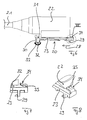
- Figure 1 shows a device, known from the prior art, for receiving a subassembly, in particular a furcation adaptor, assigned to an optical fibre cable and for fastening the subassembly received on the device to a mounting, particularly to a wall of a distribution panel or distribution cabinet via the device.
- the device 10, shown in a side view in Figure 1 has a bar-shaped basic body 11 with a topside 12 and with an underside 13.
- a guide rail 14 is formed, which extends approximately parallel to the bar-shaped basic body 11 and onto which, to receive the subassembly assigned to the optical fibre cable, the respective subassembly can be pushed in such a way that, when the subassembly is pushed onto the guide rail 14, the guide rail 14 engages into a groove formed on the subassembly to be received.
- a subassembly to be received on the device 10 is pushed onto the guide rail 14 in the direction of the arrow 15 shown in Figure 1 .
- the arrow 15 therefore indicates the direction in which a subassembly to be received by the device 10 and assigned to an optical fibre cable is pushed onto the guide rail 14.
- anchoring elements 16 and 17 are formed in the region of mutually opposite ends of the basic body 11.
- the anchoring element 16 is formed on the underside 13 of the latter, and, at the front end of the bar-shaped basic body 11, as seen in the push-on direction 15, the anchoring element 17 is formed, the device 10 according to the invention, via the two anchoring elements 16, 17, being able to be introduced into recesses of a mounting, to which the device 10, together with the subassembly received by it and assigned to the optical fibre cable, is to be fastened.
- the anchoring element 17 positioned at the front end, as seen in the push-on direction 15, of the bar-shaped basic body 11 is designed as an integral part of a stop 18 of U-shaped cross section, this stop 18 being effective in the push-on direction 15 and therefore, in the push-on direction 15, forming a stop for a subassembly to be pushed onto the guide rail 14.
- the device 10 known from the prior art, as illustrated in Figure 1 has the disadvantage that, when it is fastened via its anchoring elements 16, 17 to a mounting, for example a wall of a distribution panel or distribution cabinet, and a force is exerted on the stop 18 of U-shaped cross section via the optical fibre cable or the subassembly received by the device 10 and assigned to the optical fibre cable, the anchoring elements 16, 17 may come loose from the mounting, in that they jump out of the recesses of the mounting into which they are introduced. In this case, a secure fastening of the device 10 to the mounting is no longer ensured. This is a disadvantage.
- the problem on which the present invention is based is to provide a novel device for receiving a subassembly assigned to an optical fibre cable and for fastening the same to a mounting.
- the U-shaped stop is designed in such a way that on the underside of the basic body a closed portion of the U-shaped stop projects with respect to the latter, in such a way that, when the subassembly received on the device is fastened to the mounting, the closed portion of the U-shaped stop can be introduced into a recess of the mounting.
- the stop of U-shaped cross section is designed in such a way that the closed portion of the latter is formed on the underside of the basic body or projects with respect to the underside of the basic body. Consequently, when the device is fastened to the mounting, the closed portion of the U-shaped stop can be introduced into a recess of the mounting.
- the device according to the invention arches on its underside in such a way that the anchoring elements of the latter are hooked up in the region of the recesses of the mounting, so that there is no risk that the anchoring elements of the device come loose from the recesses of the mounting. In the device according to the invention, therefore, there is no risk that it comes loose in an unwanted way from a mounting.
- an elastically deformable stop acting opposite to the push-on direction, for the subassembly is formed at a rear end of the basic body, as seen in the push-on direction of the subassembly.
- Figures 2 and 3 show different views of a device 20 according to the invention for receiving a subassembly, such as, for example, a plug or a socket or a furcation adaptor, assigned to an optical fibre cable and for fastening the subassembly received on the device 20 to a mounting, such as, for example, a wall of a distribution panel or distribution cabinet, via the device.
- a subassembly such as, for example, a plug or a socket or a furcation adaptor
- FIGS 4 and 5 show details of the device 20 according to the invention.
- Figures 6 to 8 show the device 20 according to the invention in each case together with a subassembly 22 which is assigned to an optical fibre cable 21 and which is received on the device 20 according to the invention, the subassembly 22, shown in Figures 6 to 8 , which is assigned to the optical fibre cable 21, being what is known as a furcation adaptor.
- the device 20 has a bar-shaped basic body 23 with a topside 24 and with an underside 25.
- a guide rail 26 is formed, which extends approximately parallel to the bar-shaped basic body 23 and which is connected to the latter via portions 27.
- the subassembly 22, shown in Figure 6 which is assigned to the optical fibre cable 21 can be pushed onto the guide rail 26 in the direction of the arrow 28 shown in Figure 2 , for this purpose the guide rail 26 engaging into a groove, not illustrated in detail, which is formed on the subassembly 22.
- the arrow 28 therefore indicates the direction in which the subassembly 22 assigned to the optical fibre cable 21 is pushed onto the guide rail 26 of the device 20 according to the invention.
- anchoring elements 29 and 30 are formed, via which the device 20 according to the invention can be fastened to a mounting, in particular a wall of a distribution panel or distribution cabinet, specifically in such a way that, in this case, the anchoring elements 29, 30 can be introduced in a barb-like manner into recesses of the mountings and thus project into the recesses of the mounting.
- the anchoring element 30 positioned at the front end of the bar-shaped basic body 23, as seen in the push-on direction 28, is in this case formed as part of a stop 31 of U-shaped cross section, the stop 31 being effective, as seen in the push-on direction 28, as a stop for the subassembly 22 of the optical fibre cable 11.
- the stop 31 of U-shaped cross section is designed in such a way that a closed portion 32 of the latter is formed on the underside 25 of the bar-shaped basic body 23 or projects with respect to the underside 25 of the bar-shaped basic body 23.
- the stop 31 of U-shaped cross section is designed to be open in the region of the topside 24 of the bar-shaped basic body 23.
- the stop 31 of U-shaped cross section engages with the closed portion 32 into a recess of the mounting.
- an elastically deformable stop 34 acting opposite to the push-on direction 28, for the subassembly 22 assigned to the optical fibre cable 21 is formed at the rear end of the basic body 23, as seen in the push-on direction 28.
- the stop 34 acting opposite to the push-on direction 28 can be elastically deformed or pressed in the direction of the topside 24 of the basic body 23 both in order to push the subassembly 22 assigned to the optical fibre cable 21 onto the guide rail 26 and in order to remove the same from the guide rail 26.
- the latter has a ramp-shaped projection 35, which, according to Figures 7 and 8 , when the subassembly 22 is pushed onto the device 20, covers a contour of the subassembly 22 in regions, so that, when a force is exerted opposite to the push-on direction 28 on the optical fibre cable 21 or the subassembly 22, the subassembly 22 presses against the ramp-shaped projection 35 of the stop 34 and thus prevents the situation where the subassembly 22 can be inadvertently pushed off from the guide rail 26.
- the ramp-shaped projection 35 of the stop 34 is suppressed in the direction of the topside 24, specifically in such a way that it is pressed under the contour of the subassembly 22 and therefore does not obstruct the removal of the subassembly 22 from the device 20.
- the ramp-shaped projection 35 of the stop 34 is likewise pressed under the contour of the subassembly 22, while, after the subassembly 22 has been pushed completely onto the device 20, the stop 34 returns automatically, and the ramp-like projection 35 then once again partially covers the contour of the subassembly 22.
- the subassembly 22 can be attached to the device 10 and removed from the device 10 before and after the device 10 has been fastened to the mounting.
Landscapes
- Physics & Mathematics (AREA)
- General Physics & Mathematics (AREA)
- Optics & Photonics (AREA)
- Light Guides In General And Applications Therefor (AREA)
- Installation Of Indoor Wiring (AREA)
- Mechanical Coupling Of Light Guides (AREA)
- Telephone Function (AREA)
Abstract
Description
- The invention relates to a device for receiving a subassembly assigned to an optical fibre cable and for fastening the subassembly received on the device to a mounting via the device according to the introducing portion of claim 1.
-
Figure 1 shows a device, known from the prior art, for receiving a subassembly, in particular a furcation adaptor, assigned to an optical fibre cable and for fastening the subassembly received on the device to a mounting, particularly to a wall of a distribution panel or distribution cabinet via the device. Thedevice 10, shown in a side view inFigure 1 , has a bar-shapedbasic body 11 with atopside 12 and with anunderside 13. On thetopside 12 of thebasic body 11, aguide rail 14 is formed, which extends approximately parallel to the bar-shapedbasic body 11 and onto which, to receive the subassembly assigned to the optical fibre cable, the respective subassembly can be pushed in such a way that, when the subassembly is pushed onto theguide rail 14, theguide rail 14 engages into a groove formed on the subassembly to be received. A subassembly to be received on thedevice 10 is pushed onto theguide rail 14 in the direction of thearrow 15 shown inFigure 1 . Thearrow 15 therefore indicates the direction in which a subassembly to be received by thedevice 10 and assigned to an optical fibre cable is pushed onto theguide rail 14. - In the region of the
underside 13 of the bar-shapedbasic body 11,anchoring elements basic body 11. - Thus, at the rear end of the
basic body 11, as seen in the push-ondirection 15, theanchoring element 16 is formed on theunderside 13 of the latter, and, at the front end of the bar-shapedbasic body 11, as seen in the push-ondirection 15, theanchoring element 17 is formed, thedevice 10 according to the invention, via the twoanchoring elements device 10, together with the subassembly received by it and assigned to the optical fibre cable, is to be fastened. According toFigure 1 , in this case, the anchoringelement 17 positioned at the front end, as seen in the push-ondirection 15, of the bar-shapedbasic body 11 is designed as an integral part of astop 18 of U-shaped cross section, thisstop 18 being effective in the push-ondirection 15 and therefore, in the push-ondirection 15, forming a stop for a subassembly to be pushed onto theguide rail 14. - The
device 10 known from the prior art, as illustrated inFigure 1 , has the disadvantage that, when it is fastened via itsanchoring elements stop 18 of U-shaped cross section via the optical fibre cable or the subassembly received by thedevice 10 and assigned to the optical fibre cable, theanchoring elements device 10 to the mounting is no longer ensured. This is a disadvantage. - There is therefore a need for an improved device in which there is no risk that it comes loose unintentionally from a mounting.
- Proceeding from this, the problem on which the present invention is based is to provide a novel device for receiving a subassembly assigned to an optical fibre cable and for fastening the same to a mounting.
- This problem is solved by means of a device according to Claim 1.
- According to the invention, the U-shaped stop is designed in such a way that on the underside of the basic body a closed portion of the U-shaped stop projects with respect to the latter, in such a way that, when the subassembly received on the device is fastened to the mounting, the closed portion of the U-shaped stop can be introduced into a recess of the mounting.
- In the device according to the invention, the stop of U-shaped cross section is designed in such a way that the closed portion of the latter is formed on the underside of the basic body or projects with respect to the underside of the basic body. Consequently, when the device is fastened to the mounting, the closed portion of the U-shaped stop can be introduced into a recess of the mounting. If a force is exerted in the push-on direction on the U-shaped stop via the optical fibre cable or the subassembly which is assigned to the optical fibre cable and is pushed onto the guide rail of the device, the device according to the invention arches on its underside in such a way that the anchoring elements of the latter are hooked up in the region of the recesses of the mounting, so that there is no risk that the anchoring elements of the device come loose from the recesses of the mounting. In the device according to the invention, therefore, there is no risk that it comes loose in an unwanted way from a mounting.
- According to an advantageous development of the invention, in the region of the topside of the basic body, an elastically deformable stop, acting opposite to the push-on direction, for the subassembly is formed at a rear end of the basic body, as seen in the push-on direction of the subassembly.
- Preferred developments of the invention may be gathered from the subclaims and the following description. Exemplary embodiments are explained in more detail by means of the drawing in which:
- Figure 1
- shows a device, known from the prior art, for receiving a subas- sembly assigned to an optical fibre cable and for fastening the subassembly received on the device to a mounting, in a side view;
- Figure 2
- shows a device according to the invention for receiving a subas- sembly assigned to an optical fibre cable and for fastening the subassembly received on the device to a mounting, in a per- spective view;
- Figure 3
- shows the device of
Figure 2 in a side view; - Figure 4
- shows the detail IV of
Figure 2 ; - Figure 5
- shows the detail V of
Figure 2 ; - Figure 6
- shows the device of
Figure 2 together with an optical fibre cable and with a subassembly which is assigned to the optical fibre cable and is received on the device; - Figure 7
- shows the detail VI of
Figure 6 ; and - Figure 8
- shows the detail of
Figure 7 in a perspective view. -
Figures 2 and3 show different views of adevice 20 according to the invention for receiving a subassembly, such as, for example, a plug or a socket or a furcation adaptor, assigned to an optical fibre cable and for fastening the subassembly received on thedevice 20 to a mounting, such as, for example, a wall of a distribution panel or distribution cabinet, via the device. -
Figures 4 and 5 show details of thedevice 20 according to the invention. -
Figures 6 to 8 show thedevice 20 according to the invention in each case together with asubassembly 22 which is assigned to anoptical fibre cable 21 and which is received on thedevice 20 according to the invention, thesubassembly 22, shown inFigures 6 to 8 , which is assigned to theoptical fibre cable 21, being what is known as a furcation adaptor. - The
device 20 according to the invention has a bar-shapedbasic body 23 with atopside 24 and with anunderside 25. On thetopside 24 of the bar-shapedbasic body 23, aguide rail 26 is formed, which extends approximately parallel to the bar-shapedbasic body 23 and which is connected to the latter viaportions 27. - The
subassembly 22, shown inFigure 6 , which is assigned to theoptical fibre cable 21 can be pushed onto theguide rail 26 in the direction of thearrow 28 shown inFigure 2 , for this purpose theguide rail 26 engaging into a groove, not illustrated in detail, which is formed on thesubassembly 22. Thearrow 28 therefore indicates the direction in which thesubassembly 22 assigned to theoptical fibre cable 21 is pushed onto theguide rail 26 of thedevice 20 according to the invention. - At mutually opposite ends of the bar-shaped
basic body 23,anchoring elements device 20 according to the invention can be fastened to a mounting, in particular a wall of a distribution panel or distribution cabinet, specifically in such a way that, in this case, theanchoring elements - The anchoring
element 30 positioned at the front end of the bar-shapedbasic body 23, as seen in the push-ondirection 28, is in this case formed as part of astop 31 of U-shaped cross section, thestop 31 being effective, as seen in the push-ondirection 28, as a stop for thesubassembly 22 of theoptical fibre cable 11. - According to this invention, the
stop 31 of U-shaped cross section is designed in such a way that a closedportion 32 of the latter is formed on theunderside 25 of the bar-shapedbasic body 23 or projects with respect to theunderside 25 of the bar-shapedbasic body 23. By contrast, thestop 31 of U-shaped cross section is designed to be open in the region of thetopside 24 of the bar-shapedbasic body 23. - When the
device 20 according to the invention, together with asubassembly 22 received on the latter and assigned to theoptical fibre cable 21, is to be fastened to a mounting, thestop 31 of U-shaped cross section engages with the closedportion 32 into a recess of the mounting. - When a force is exerted on the
stop 31 in the push-ondirection 28 via theoptical fibre cable 21 or via thesubassembly 22 assigned to theoptical fibre cable 21, thestop 31 of U-shaped cross section is subjected, according toFigure 6 , to a deformation in the direction of thearrow 33, with the result that the bar-shaped body 23 ultimately arches and theanchoring elements - There is then no risk that the
anchoring elements device 20 comes loose from the mounting inadvertently. - According to an advantageous development of the invention, in the region of the
topside 24 of the bar-shapedbasic body 23, an elasticallydeformable stop 34 acting opposite to the push-ondirection 28, for thesubassembly 22 assigned to theoptical fibre cable 21 is formed at the rear end of thebasic body 23, as seen in the push-ondirection 28. - The
stop 34 acting opposite to the push-ondirection 28 can be elastically deformed or pressed in the direction of thetopside 24 of thebasic body 23 both in order to push thesubassembly 22 assigned to theoptical fibre cable 21 onto theguide rail 26 and in order to remove the same from theguide rail 26. - At the free end of the elastically
deformable stop 34, the latter has a ramp-shaped projection 35, which, according toFigures 7 and 8 , when thesubassembly 22 is pushed onto thedevice 20, covers a contour of thesubassembly 22 in regions, so that, when a force is exerted opposite to the push-ondirection 28 on theoptical fibre cable 21 or thesubassembly 22, thesubassembly 22 presses against the ramp-shaped projection 35 of thestop 34 and thus prevents the situation where thesubassembly 22 can be inadvertently pushed off from theguide rail 26. - If the
subassembly 22 is to be intentionally removed from thedevice 20, the ramp-shaped projection 35 of thestop 34 is suppressed in the direction of thetopside 24, specifically in such a way that it is pressed under the contour of thesubassembly 22 and therefore does not obstruct the removal of thesubassembly 22 from thedevice 20. When thesubassembly 22 is pushed onto thedevice 20 or theguide rail 26 of the latter, the ramp-shaped projection 35 of thestop 34 is likewise pressed under the contour of thesubassembly 22, while, after thesubassembly 22 has been pushed completely onto thedevice 20, thestop 34 returns automatically, and the ramp-like projection 35 then once again partially covers the contour of thesubassembly 22. - The
subassembly 22 can be attached to thedevice 10 and removed from thedevice 10 before and after thedevice 10 has been fastened to the mounting. -
- 10
- device
- 11
- basic body
- 12
- topside
- 13
- underside
- 14
- guide rail
- 15
- push-on direction
- 16
- anchoring element
- 17
- anchoring element
- 18
- stop
- 20
- device
- 21
- optical fibre cable
- 22
- subassembly
- 23
- basic body
- 24
- topside
- 25
- underside
- 26
- guide rail
- 27
- portion
- 28
- push-on direction
- 29
- anchoring element
- 30
- anchoring element
- 31
- stop
- 32
- portion
- 33
- arrow
- 34
- stop
- 35
- projection
Claims (5)
- Device for receiving a subassembly, in particular a plug or a socket or a furcation adaptor, assigned to an optical fibre cable and for fastening the subassembly received on the device to a mounting, in particular to a wall of a distribution panel or distribution cabinet, via the device, with a bar-shaped basic body (23), there being formed on a topside of the basic body a guide rail (26), onto which, to receive the subassembly assigned to the optical fibre cable, the latter can be pushed, there being formed on an underside, in the region of mutually opposite ends of the basic body, anchoring elements (29, 30), via which the device can be introduced into recesses of the mounting, and the anchoring element (30), which is assigned to a front end of the basic body (23) as seen in the push-on direction of the subassembly, being an integral part of a stop (31) of U-shaped cross section, acting in the push-on direction, for the subassembly, characterized in that the stop (31) of U-shaped cross section is designed in such a way that a closed portion (32) of the U-shaped stop (31) on the underside (25) of the basic body (23) projects with respect to the latter, in such a way that, when the subassembly received on the device is fastened to the mounting, the closed portion (32) of the U-shaped stop (31) can be introduced into a recess of the mounting.
- Device according to Claim 1, characterized in that, in the region of the topside (24) of the basic body (23), an elastically deformable stop (34), acting opposite to the push-on direction, for the subassembly is formed at a rear end of the basic body (23), as seen in the push-direction of the subassembly.
- Device according to Claim 2, characterized in that, to push the subassembly assigned to the optical fibre cable onto the guide rail (26), the stop (34) acting opposite to the push-on direction can be pressed elastically in the direction of the topside (24) of the basic body (23).
- Device according to Claim 2 or 3, characterized in that, to remove the subassembly assigned to the optical fibre cable from the guide rail (26), the stop (34) acting opposite to the push-on direction can be pressed elastically in the direction of the topside (24) of the basic body (23).
- Device according to Claim 3 or 4, characterized in that, in this case, a ramp-shaped projection (35) of the stop (34) can be pressed under a contour of the subassembly to be pushed on or to be removed, so that the stop (34) does not obstruct the pushing or removal of the subassembly assigned to the optical fibre cable onto or from the guide rail (26), the ramp-shaped projection (35) of the stop (34) subsequently returning automatically, so that, when the subassembly is pushed onto the guide rail (26), the ramp-shaped projection (35) partially covers the contour of the pushed-on subassembly and forms the stop (34), acting opposite to the push-on direction, for the subassembly.
Priority Applications (6)
| Application Number | Priority Date | Filing Date | Title |
|---|---|---|---|
| PT08014476T PT2154556E (en) | 2008-08-14 | 2008-08-14 | METHOD FOR THE MANAGEMENT OF INFORMATION PARTS AND DATA STORED IN AN ELECTRONIC TYPE TELEPHONE UNIT |
| EP08014476A EP2154556B1 (en) | 2008-08-14 | 2008-08-14 | Device for receiving a subassembly assigned to an optical fibre cable and for fastening the same to a mounting |
| AT08014476T ATE534927T1 (en) | 2008-08-14 | 2008-08-14 | DEVICE FOR RECEIVING A SUB-ASSEMBLY ASSOCIATED WITH AN OPTICAL FIBER CABLE AND ATTACHING THE SAME TO A DEVICE |
| ES08014476T ES2376676T3 (en) | 2008-08-14 | 2008-08-14 | DEVICE FOR RECEIVING A SUBCONJUNCT ASSIGNED TO AN OPTICAL FIBER CABLE AND TO BE FIXED IN AN ASSEMBLY. |
| AU2009203003A AU2009203003B2 (en) | 2008-08-14 | 2009-07-23 | Device for receiving a subassembly assigned to an optical fibre cable and for fastening the same to a mounting |
| US12/541,637 US8218936B2 (en) | 2008-08-14 | 2009-08-14 | Device for receiving a subassembly assigned to an optical fiber cable and for fastening the same to a mounting |
Applications Claiming Priority (1)
| Application Number | Priority Date | Filing Date | Title |
|---|---|---|---|
| EP08014476A EP2154556B1 (en) | 2008-08-14 | 2008-08-14 | Device for receiving a subassembly assigned to an optical fibre cable and for fastening the same to a mounting |
Publications (2)
| Publication Number | Publication Date |
|---|---|
| EP2154556A1 true EP2154556A1 (en) | 2010-02-17 |
| EP2154556B1 EP2154556B1 (en) | 2011-11-23 |
Family
ID=39847053
Family Applications (1)
| Application Number | Title | Priority Date | Filing Date |
|---|---|---|---|
| EP08014476A Not-in-force EP2154556B1 (en) | 2008-08-14 | 2008-08-14 | Device for receiving a subassembly assigned to an optical fibre cable and for fastening the same to a mounting |
Country Status (6)
| Country | Link |
|---|---|
| US (1) | US8218936B2 (en) |
| EP (1) | EP2154556B1 (en) |
| AT (1) | ATE534927T1 (en) |
| AU (1) | AU2009203003B2 (en) |
| ES (1) | ES2376676T3 (en) |
| PT (1) | PT2154556E (en) |
Cited By (3)
| Publication number | Priority date | Publication date | Assignee | Title |
|---|---|---|---|---|
| WO2011137326A1 (en) | 2010-04-30 | 2011-11-03 | Corning Cable Systems Llc | Mounting and strain relief device for optical cables |
| US8625952B2 (en) | 2011-07-13 | 2014-01-07 | Corning Cable Systems Llc | Fiber optic cable mounting adapters, and related fiber optic cable assemblies and methods |
| CN105022130A (en) * | 2015-07-24 | 2015-11-04 | 成都前宏通讯有限责任公司 | Self-supporting fixing piece used in optical fiber routing process |
Families Citing this family (29)
| Publication number | Priority date | Publication date | Assignee | Title |
|---|---|---|---|---|
| US8559786B2 (en) * | 2009-09-28 | 2013-10-15 | Ccs Technology, Inc. | Device for receiving subassemblies assigned to at least one optical fiber cable and for fastening the same to a mounting |
| US12571977B2 (en) | 2017-06-28 | 2026-03-10 | Corning Research & Development Corporation | Multiports and other devices having optical connection ports with securing features and methods of making the same |
| CN111065946B (en) | 2017-06-28 | 2023-08-18 | 康宁研究与开发公司 | Multiport and other devices having keyed connection ports and securing features and methods of manufacture |
| US12271040B2 (en) | 2017-06-28 | 2025-04-08 | Corning Research & Development Corporation | Fiber optic extender ports, assemblies and methods of making the same |
| US11668890B2 (en) | 2017-06-28 | 2023-06-06 | Corning Research & Development Corporation | Multiports and other devices having optical connection ports with securing features and methods of making the same |
| US10359577B2 (en) | 2017-06-28 | 2019-07-23 | Corning Research & Development Corporation | Multiports and optical connectors with rotationally discrete locking and keying features |
| US11300746B2 (en) | 2017-06-28 | 2022-04-12 | Corning Research & Development Corporation | Fiber optic port module inserts, assemblies and methods of making the same |
| USD1002540S1 (en) | 2017-11-30 | 2023-10-24 | Corning Research & Development Corporation | Connector for making optical connections |
| EP3887883B1 (en) | 2018-11-29 | 2023-11-08 | Corning Research & Development Corporation | Multiport having connection ports with rotating actuators |
| EP3903136B1 (en) * | 2018-12-28 | 2024-11-06 | Corning Research & Development Corporation | Multiport assemblies including mounting features or dust plugs |
| MX2021014427A (en) | 2019-05-31 | 2022-03-04 | Corning Res & Dev Corp | MULTIPORTS AND OTHER DEVICES THAT HAVE OPTICAL CONNECTION PORTS WITH SLIDING ACTUATORS AND METHODS FOR MAKING SAME. |
| US11294133B2 (en) | 2019-07-31 | 2022-04-05 | Corning Research & Development Corporation | Fiber optic networks using multiports and cable assemblies with cable-to-connector orientation |
| US11487073B2 (en) | 2019-09-30 | 2022-11-01 | Corning Research & Development Corporation | Cable input devices having an integrated locking feature and assemblies using the cable input devices |
| EP3805827B1 (en) | 2019-10-07 | 2025-07-30 | Corning Research & Development Corporation | Fiber optic terminals and fiber optic networks having variable ratio couplers |
| WO2021076325A1 (en) | 2019-10-18 | 2021-04-22 | Corning Research & Development Corporation | Terminals having optical connection ports with securing features providing stable retention forces and methods of making the same |
| US11650388B2 (en) | 2019-11-14 | 2023-05-16 | Corning Research & Development Corporation | Fiber optic networks having a self-supporting optical terminal and methods of installing the optical terminal |
| USD949107S1 (en) | 2019-12-20 | 2022-04-19 | Corning Research & Development Corporation | Dustplug for a multiport optical connection device |
| US11536921B2 (en) | 2020-02-11 | 2022-12-27 | Corning Research & Development Corporation | Fiber optic terminals having one or more loopback assemblies |
| EP4172671B1 (en) | 2020-06-29 | 2026-01-21 | Corning Research & Development Corporation | Terminals having a multi-fiber optical connection port that inhibits damage from single-fiber connectors |
| US11604320B2 (en) | 2020-09-30 | 2023-03-14 | Corning Research & Development Corporation | Connector assemblies for telecommunication enclosures |
| US11462897B2 (en) | 2020-10-22 | 2022-10-04 | Afl Telecommunications Llc | Cable mounting clamps |
| PL4237889T3 (en) | 2020-10-30 | 2026-01-26 | Corning Research & Development Corporation | FEMALE FIBER OPTIC CONNECTORS WITH LOCKING ARM WITH ROCKING MECHANISM |
| US11927810B2 (en) | 2020-11-30 | 2024-03-12 | Corning Research & Development Corporation | Fiber optic adapter assemblies including a conversion housing and a release member |
| US11686913B2 (en) | 2020-11-30 | 2023-06-27 | Corning Research & Development Corporation | Fiber optic cable assemblies and connector assemblies having a crimp ring and crimp body and methods of fabricating the same |
| US11994722B2 (en) | 2020-11-30 | 2024-05-28 | Corning Research & Development Corporation | Fiber optic adapter assemblies including an adapter housing and a locking housing |
| US11880076B2 (en) | 2020-11-30 | 2024-01-23 | Corning Research & Development Corporation | Fiber optic adapter assemblies including a conversion housing and a release housing |
| EP4314920A1 (en) | 2021-03-31 | 2024-02-07 | AFL Telecommunications LLC | Cable mounting clamps |
| US11947167B2 (en) | 2021-05-26 | 2024-04-02 | Corning Research & Development Corporation | Fiber optic terminals and tools and methods for adjusting a split ratio of a fiber optic terminal |
| USD1060249S1 (en) | 2021-08-30 | 2025-02-04 | Corning Research & Development Corporation | Multifiber connector for making optical connections |
Citations (2)
| Publication number | Priority date | Publication date | Assignee | Title |
|---|---|---|---|---|
| DE9316137U1 (en) * | 1993-10-22 | 1993-12-16 | Philips Patentverwaltung Gmbh, 20097 Hamburg | Arrangement for holding optical fiber coupling carriers |
| US20070047897A1 (en) * | 2005-08-31 | 2007-03-01 | Cooke Terry L | Fiber optic universal bracket apparatus and methods |
Family Cites Families (2)
| Publication number | Priority date | Publication date | Assignee | Title |
|---|---|---|---|---|
| US6845207B2 (en) * | 2001-02-12 | 2005-01-18 | Fiber Optic Network Solutions Corp. | Optical fiber enclosure system |
| GB0423743D0 (en) * | 2004-10-26 | 2004-11-24 | Tyco Electronics Raychem Nv | A signal distribution assembly and a connector holder for use therewith |
-
2008
- 2008-08-14 AT AT08014476T patent/ATE534927T1/en active
- 2008-08-14 EP EP08014476A patent/EP2154556B1/en not_active Not-in-force
- 2008-08-14 PT PT08014476T patent/PT2154556E/en unknown
- 2008-08-14 ES ES08014476T patent/ES2376676T3/en active Active
-
2009
- 2009-07-23 AU AU2009203003A patent/AU2009203003B2/en not_active Ceased
- 2009-08-14 US US12/541,637 patent/US8218936B2/en not_active Expired - Fee Related
Patent Citations (2)
| Publication number | Priority date | Publication date | Assignee | Title |
|---|---|---|---|---|
| DE9316137U1 (en) * | 1993-10-22 | 1993-12-16 | Philips Patentverwaltung Gmbh, 20097 Hamburg | Arrangement for holding optical fiber coupling carriers |
| US20070047897A1 (en) * | 2005-08-31 | 2007-03-01 | Cooke Terry L | Fiber optic universal bracket apparatus and methods |
Cited By (3)
| Publication number | Priority date | Publication date | Assignee | Title |
|---|---|---|---|---|
| WO2011137326A1 (en) | 2010-04-30 | 2011-11-03 | Corning Cable Systems Llc | Mounting and strain relief device for optical cables |
| US8625952B2 (en) | 2011-07-13 | 2014-01-07 | Corning Cable Systems Llc | Fiber optic cable mounting adapters, and related fiber optic cable assemblies and methods |
| CN105022130A (en) * | 2015-07-24 | 2015-11-04 | 成都前宏通讯有限责任公司 | Self-supporting fixing piece used in optical fiber routing process |
Also Published As
| Publication number | Publication date |
|---|---|
| AU2009203003A1 (en) | 2010-03-04 |
| ATE534927T1 (en) | 2011-12-15 |
| AU2009203003B2 (en) | 2014-07-24 |
| US8218936B2 (en) | 2012-07-10 |
| EP2154556B1 (en) | 2011-11-23 |
| PT2154556E (en) | 2012-02-06 |
| ES2376676T3 (en) | 2012-03-15 |
| US20100040338A1 (en) | 2010-02-18 |
Similar Documents
| Publication | Publication Date | Title |
|---|---|---|
| EP2154556B1 (en) | Device for receiving a subassembly assigned to an optical fibre cable and for fastening the same to a mounting | |
| CN102195195B (en) | Closure assembly, strain relief element and method for connector | |
| RU2625250C2 (en) | Optical connector for cables with outer sheath | |
| US7661887B2 (en) | Shutter assembly | |
| US9405068B2 (en) | Strain relieved adapter for a jacketed cable and boot | |
| KR101422991B1 (en) | Optical connector | |
| CN101669054B (en) | Optical fiber connector and optical cable | |
| AU2002327890B2 (en) | Universal adapter | |
| US7648286B2 (en) | Shutter assembly | |
| KR20150067075A (en) | Fixing device for cables | |
| CN101523107A (en) | Coupling part for a fluid line coupling | |
| IL184447A0 (en) | Optical data transmission cable plug connection with fakra housing | |
| EP3159976A1 (en) | Label-holder element for electric wires | |
| US8737797B2 (en) | Device for receiving a subassembly assigned to an optical fibre cable and for fastening the same to a mounting | |
| JP2009282177A (en) | Bent boot for optical connector | |
| KR101914924B1 (en) | Windscreen wiper device for a motor vehicle | |
| MX2009013700A (en) | Connector for multiple optical fibers and installation apparatus. | |
| HUP0302203A2 (en) | Coupling device for glass fiber connectors | |
| EP1901400A3 (en) | A wire cover and a locking construction therefor | |
| EP2302430A1 (en) | Device for receiving subassemblies assigned to at least one optical fiber cable and for fastening the same to a mounting | |
| KR20090063725A (en) | Connector | |
| KR101185537B1 (en) | Field installable optical fiber connector | |
| US20150007432A1 (en) | Modular RJ Connector Latch Replacement | |
| EP1574781A2 (en) | Light shield mounting for automotive headlamp | |
| JP2012048031A (en) | Optical fiber alignment fixture and optical cable terminal processing method |
Legal Events
| Date | Code | Title | Description |
|---|---|---|---|
| PUAI | Public reference made under article 153(3) epc to a published international application that has entered the european phase |
Free format text: ORIGINAL CODE: 0009012 |
|
| AK | Designated contracting states |
Kind code of ref document: A1 Designated state(s): AT BE BG CH CY CZ DE DK EE ES FI FR GB GR HR HU IE IS IT LI LT LU LV MC MT NL NO PL PT RO SE SI SK TR |
|
| AX | Request for extension of the european patent |
Extension state: AL BA MK RS |
|
| 17P | Request for examination filed |
Effective date: 20100809 |
|
| 17Q | First examination report despatched |
Effective date: 20100908 |
|
| AKX | Designation fees paid |
Designated state(s): AT BE BG CH CY CZ DE DK EE ES FI FR GB GR HR HU IE IS IT LI LT LU LV MC MT NL NO PL PT RO SE SI SK TR |
|
| GRAP | Despatch of communication of intention to grant a patent |
Free format text: ORIGINAL CODE: EPIDOSNIGR1 |
|
| GRAS | Grant fee paid |
Free format text: ORIGINAL CODE: EPIDOSNIGR3 |
|
| GRAA | (expected) grant |
Free format text: ORIGINAL CODE: 0009210 |
|
| AK | Designated contracting states |
Kind code of ref document: B1 Designated state(s): AT BE BG CH CY CZ DE DK EE ES FI FR GB GR HR HU IE IS IT LI LT LU LV MC MT NL NO PL PT RO SE SI SK TR |
|
| REG | Reference to a national code |
Ref country code: GB Ref legal event code: FG4D |
|
| REG | Reference to a national code |
Ref country code: CH Ref legal event code: EP |
|
| REG | Reference to a national code |
Ref country code: IE Ref legal event code: FG4D |
|
| REG | Reference to a national code |
Ref country code: DE Ref legal event code: R096 Ref document number: 602008011501 Country of ref document: DE Effective date: 20120119 |
|
| REG | Reference to a national code |
Ref country code: PT Ref legal event code: SC4A Free format text: AVAILABILITY OF NATIONAL TRANSLATION Effective date: 20120126 |
|
| REG | Reference to a national code |
Ref country code: NL Ref legal event code: VDEP Effective date: 20111123 |
|
| REG | Reference to a national code |
Ref country code: ES Ref legal event code: FG2A Ref document number: 2376676 Country of ref document: ES Kind code of ref document: T3 Effective date: 20120315 |
|
| LTIE | Lt: invalidation of european patent or patent extension |
Effective date: 20111123 |
|
| PG25 | Lapsed in a contracting state [announced via postgrant information from national office to epo] |
Ref country code: NO Free format text: LAPSE BECAUSE OF FAILURE TO SUBMIT A TRANSLATION OF THE DESCRIPTION OR TO PAY THE FEE WITHIN THE PRESCRIBED TIME-LIMIT Effective date: 20120223 Ref country code: LT Free format text: LAPSE BECAUSE OF FAILURE TO SUBMIT A TRANSLATION OF THE DESCRIPTION OR TO PAY THE FEE WITHIN THE PRESCRIBED TIME-LIMIT Effective date: 20111123 Ref country code: IS Free format text: LAPSE BECAUSE OF FAILURE TO SUBMIT A TRANSLATION OF THE DESCRIPTION OR TO PAY THE FEE WITHIN THE PRESCRIBED TIME-LIMIT Effective date: 20120323 |
|
| PG25 | Lapsed in a contracting state [announced via postgrant information from national office to epo] |
Ref country code: GR Free format text: LAPSE BECAUSE OF FAILURE TO SUBMIT A TRANSLATION OF THE DESCRIPTION OR TO PAY THE FEE WITHIN THE PRESCRIBED TIME-LIMIT Effective date: 20120224 Ref country code: NL Free format text: LAPSE BECAUSE OF FAILURE TO SUBMIT A TRANSLATION OF THE DESCRIPTION OR TO PAY THE FEE WITHIN THE PRESCRIBED TIME-LIMIT Effective date: 20111123 Ref country code: LV Free format text: LAPSE BECAUSE OF FAILURE TO SUBMIT A TRANSLATION OF THE DESCRIPTION OR TO PAY THE FEE WITHIN THE PRESCRIBED TIME-LIMIT Effective date: 20111123 Ref country code: SE Free format text: LAPSE BECAUSE OF FAILURE TO SUBMIT A TRANSLATION OF THE DESCRIPTION OR TO PAY THE FEE WITHIN THE PRESCRIBED TIME-LIMIT Effective date: 20111123 Ref country code: SI Free format text: LAPSE BECAUSE OF FAILURE TO SUBMIT A TRANSLATION OF THE DESCRIPTION OR TO PAY THE FEE WITHIN THE PRESCRIBED TIME-LIMIT Effective date: 20111123 Ref country code: HR Free format text: LAPSE BECAUSE OF FAILURE TO SUBMIT A TRANSLATION OF THE DESCRIPTION OR TO PAY THE FEE WITHIN THE PRESCRIBED TIME-LIMIT Effective date: 20111123 Ref country code: BE Free format text: LAPSE BECAUSE OF FAILURE TO SUBMIT A TRANSLATION OF THE DESCRIPTION OR TO PAY THE FEE WITHIN THE PRESCRIBED TIME-LIMIT Effective date: 20111123 |
|
| PG25 | Lapsed in a contracting state [announced via postgrant information from national office to epo] |
Ref country code: CY Free format text: LAPSE BECAUSE OF FAILURE TO SUBMIT A TRANSLATION OF THE DESCRIPTION OR TO PAY THE FEE WITHIN THE PRESCRIBED TIME-LIMIT Effective date: 20111123 |
|
| PG25 | Lapsed in a contracting state [announced via postgrant information from national office to epo] |
Ref country code: CZ Free format text: LAPSE BECAUSE OF FAILURE TO SUBMIT A TRANSLATION OF THE DESCRIPTION OR TO PAY THE FEE WITHIN THE PRESCRIBED TIME-LIMIT Effective date: 20111123 Ref country code: DK Free format text: LAPSE BECAUSE OF FAILURE TO SUBMIT A TRANSLATION OF THE DESCRIPTION OR TO PAY THE FEE WITHIN THE PRESCRIBED TIME-LIMIT Effective date: 20111123 Ref country code: EE Free format text: LAPSE BECAUSE OF FAILURE TO SUBMIT A TRANSLATION OF THE DESCRIPTION OR TO PAY THE FEE WITHIN THE PRESCRIBED TIME-LIMIT Effective date: 20111123 Ref country code: BG Free format text: LAPSE BECAUSE OF FAILURE TO SUBMIT A TRANSLATION OF THE DESCRIPTION OR TO PAY THE FEE WITHIN THE PRESCRIBED TIME-LIMIT Effective date: 20120223 Ref country code: SK Free format text: LAPSE BECAUSE OF FAILURE TO SUBMIT A TRANSLATION OF THE DESCRIPTION OR TO PAY THE FEE WITHIN THE PRESCRIBED TIME-LIMIT Effective date: 20111123 |
|
| PG25 | Lapsed in a contracting state [announced via postgrant information from national office to epo] |
Ref country code: PL Free format text: LAPSE BECAUSE OF FAILURE TO SUBMIT A TRANSLATION OF THE DESCRIPTION OR TO PAY THE FEE WITHIN THE PRESCRIBED TIME-LIMIT Effective date: 20111123 Ref country code: RO Free format text: LAPSE BECAUSE OF FAILURE TO SUBMIT A TRANSLATION OF THE DESCRIPTION OR TO PAY THE FEE WITHIN THE PRESCRIBED TIME-LIMIT Effective date: 20111123 |
|
| REG | Reference to a national code |
Ref country code: AT Ref legal event code: MK05 Ref document number: 534927 Country of ref document: AT Kind code of ref document: T Effective date: 20111123 |
|
| PLBE | No opposition filed within time limit |
Free format text: ORIGINAL CODE: 0009261 |
|
| STAA | Information on the status of an ep patent application or granted ep patent |
Free format text: STATUS: NO OPPOSITION FILED WITHIN TIME LIMIT |
|
| 26N | No opposition filed |
Effective date: 20120824 |
|
| REG | Reference to a national code |
Ref country code: DE Ref legal event code: R097 Ref document number: 602008011501 Country of ref document: DE Effective date: 20120824 |
|
| PGFP | Annual fee paid to national office [announced via postgrant information from national office to epo] |
Ref country code: IT Payment date: 20120822 Year of fee payment: 5 |
|
| PG25 | Lapsed in a contracting state [announced via postgrant information from national office to epo] |
Ref country code: AT Free format text: LAPSE BECAUSE OF FAILURE TO SUBMIT A TRANSLATION OF THE DESCRIPTION OR TO PAY THE FEE WITHIN THE PRESCRIBED TIME-LIMIT Effective date: 20111123 |
|
| PGFP | Annual fee paid to national office [announced via postgrant information from national office to epo] |
Ref country code: PT Payment date: 20120126 Year of fee payment: 5 |
|
| PG25 | Lapsed in a contracting state [announced via postgrant information from national office to epo] |
Ref country code: MC Free format text: LAPSE BECAUSE OF NON-PAYMENT OF DUE FEES Effective date: 20120831 |
|
| REG | Reference to a national code |
Ref country code: IE Ref legal event code: MM4A |
|
| PG25 | Lapsed in a contracting state [announced via postgrant information from national office to epo] |
Ref country code: FI Free format text: LAPSE BECAUSE OF FAILURE TO SUBMIT A TRANSLATION OF THE DESCRIPTION OR TO PAY THE FEE WITHIN THE PRESCRIBED TIME-LIMIT Effective date: 20111123 |
|
| PG25 | Lapsed in a contracting state [announced via postgrant information from national office to epo] |
Ref country code: IE Free format text: LAPSE BECAUSE OF NON-PAYMENT OF DUE FEES Effective date: 20120814 |
|
| PG25 | Lapsed in a contracting state [announced via postgrant information from national office to epo] |
Ref country code: MT Free format text: LAPSE BECAUSE OF FAILURE TO SUBMIT A TRANSLATION OF THE DESCRIPTION OR TO PAY THE FEE WITHIN THE PRESCRIBED TIME-LIMIT Effective date: 20111123 |
|
| PGFP | Annual fee paid to national office [announced via postgrant information from national office to epo] |
Ref country code: GB Payment date: 20130827 Year of fee payment: 6 |
|
| REG | Reference to a national code |
Ref country code: PT Ref legal event code: MM4A Free format text: LAPSE DUE TO NON-PAYMENT OF FEES Effective date: 20140214 |
|
| REG | Reference to a national code |
Ref country code: CH Ref legal event code: PL |
|
| PG25 | Lapsed in a contracting state [announced via postgrant information from national office to epo] |
Ref country code: CH Free format text: LAPSE BECAUSE OF NON-PAYMENT OF DUE FEES Effective date: 20130831 Ref country code: LI Free format text: LAPSE BECAUSE OF NON-PAYMENT OF DUE FEES Effective date: 20130831 Ref country code: TR Free format text: LAPSE BECAUSE OF FAILURE TO SUBMIT A TRANSLATION OF THE DESCRIPTION OR TO PAY THE FEE WITHIN THE PRESCRIBED TIME-LIMIT Effective date: 20111123 |
|
| PG25 | Lapsed in a contracting state [announced via postgrant information from national office to epo] |
Ref country code: IT Free format text: LAPSE BECAUSE OF NON-PAYMENT OF DUE FEES Effective date: 20130814 Ref country code: LU Free format text: LAPSE BECAUSE OF NON-PAYMENT OF DUE FEES Effective date: 20120814 |
|
| PG25 | Lapsed in a contracting state [announced via postgrant information from national office to epo] |
Ref country code: PT Free format text: LAPSE BECAUSE OF NON-PAYMENT OF DUE FEES Effective date: 20140214 |
|
| PG25 | Lapsed in a contracting state [announced via postgrant information from national office to epo] |
Ref country code: HU Free format text: LAPSE BECAUSE OF FAILURE TO SUBMIT A TRANSLATION OF THE DESCRIPTION OR TO PAY THE FEE WITHIN THE PRESCRIBED TIME-LIMIT Effective date: 20080814 |
|
| GBPC | Gb: european patent ceased through non-payment of renewal fee |
Effective date: 20140814 |
|
| PG25 | Lapsed in a contracting state [announced via postgrant information from national office to epo] |
Ref country code: GB Free format text: LAPSE BECAUSE OF NON-PAYMENT OF DUE FEES Effective date: 20140814 |
|
| REG | Reference to a national code |
Ref country code: FR Ref legal event code: PLFP Year of fee payment: 8 |
|
| REG | Reference to a national code |
Ref country code: FR Ref legal event code: PLFP Year of fee payment: 9 |
|
| REG | Reference to a national code |
Ref country code: FR Ref legal event code: PLFP Year of fee payment: 10 |
|
| REG | Reference to a national code |
Ref country code: FR Ref legal event code: PLFP Year of fee payment: 11 |
|
| PGFP | Annual fee paid to national office [announced via postgrant information from national office to epo] |
Ref country code: DE Payment date: 20190715 Year of fee payment: 12 Ref country code: ES Payment date: 20190902 Year of fee payment: 12 Ref country code: FR Payment date: 20190717 Year of fee payment: 12 |
|
| REG | Reference to a national code |
Ref country code: DE Ref legal event code: R119 Ref document number: 602008011501 Country of ref document: DE |
|
| PG25 | Lapsed in a contracting state [announced via postgrant information from national office to epo] |
Ref country code: FR Free format text: LAPSE BECAUSE OF NON-PAYMENT OF DUE FEES Effective date: 20200831 Ref country code: DE Free format text: LAPSE BECAUSE OF NON-PAYMENT OF DUE FEES Effective date: 20210302 |
|
| REG | Reference to a national code |
Ref country code: ES Ref legal event code: FD2A Effective date: 20220110 |
|
| PG25 | Lapsed in a contracting state [announced via postgrant information from national office to epo] |
Ref country code: ES Free format text: LAPSE BECAUSE OF NON-PAYMENT OF DUE FEES Effective date: 20200815 |