EP2154500A2 - Multi-zone non-contact spot thermometer - Google Patents
Multi-zone non-contact spot thermometer Download PDFInfo
- Publication number
- EP2154500A2 EP2154500A2 EP09251968A EP09251968A EP2154500A2 EP 2154500 A2 EP2154500 A2 EP 2154500A2 EP 09251968 A EP09251968 A EP 09251968A EP 09251968 A EP09251968 A EP 09251968A EP 2154500 A2 EP2154500 A2 EP 2154500A2
- Authority
- EP
- European Patent Office
- Prior art keywords
- measurement
- detector
- detectors
- optical
- optical system
- Prior art date
- Legal status (The legal status is an assumption and is not a legal conclusion. Google has not performed a legal analysis and makes no representation as to the accuracy of the status listed.)
- Withdrawn
Links
Images



Classifications
-
- G—PHYSICS
- G01—MEASURING; TESTING
- G01J—MEASUREMENT OF INTENSITY, VELOCITY, SPECTRAL CONTENT, POLARISATION, PHASE OR PULSE CHARACTERISTICS OF INFRARED, VISIBLE OR ULTRAVIOLET LIGHT; COLORIMETRY; RADIATION PYROMETRY
- G01J5/00—Radiation pyrometry, e.g. infrared or optical thermometry
- G01J5/02—Constructional details
- G01J5/08—Optical arrangements
-
- G—PHYSICS
- G01—MEASURING; TESTING
- G01J—MEASUREMENT OF INTENSITY, VELOCITY, SPECTRAL CONTENT, POLARISATION, PHASE OR PULSE CHARACTERISTICS OF INFRARED, VISIBLE OR ULTRAVIOLET LIGHT; COLORIMETRY; RADIATION PYROMETRY
- G01J5/00—Radiation pyrometry, e.g. infrared or optical thermometry
- G01J5/02—Constructional details
- G01J5/07—Arrangements for adjusting the solid angle of collected radiation, e.g. adjusting or orienting field of view, tracking position or encoding angular position
-
- G—PHYSICS
- G01—MEASURING; TESTING
- G01J—MEASUREMENT OF INTENSITY, VELOCITY, SPECTRAL CONTENT, POLARISATION, PHASE OR PULSE CHARACTERISTICS OF INFRARED, VISIBLE OR ULTRAVIOLET LIGHT; COLORIMETRY; RADIATION PYROMETRY
- G01J5/00—Radiation pyrometry, e.g. infrared or optical thermometry
- G01J5/02—Constructional details
- G01J5/08—Optical arrangements
- G01J5/0806—Focusing or collimating elements, e.g. lenses or concave mirrors
-
- G—PHYSICS
- G01—MEASURING; TESTING
- G01J—MEASUREMENT OF INTENSITY, VELOCITY, SPECTRAL CONTENT, POLARISATION, PHASE OR PULSE CHARACTERISTICS OF INFRARED, VISIBLE OR ULTRAVIOLET LIGHT; COLORIMETRY; RADIATION PYROMETRY
- G01J5/00—Radiation pyrometry, e.g. infrared or optical thermometry
- G01J5/02—Constructional details
- G01J5/08—Optical arrangements
- G01J5/084—Adjustable or slidable
-
- G—PHYSICS
- G01—MEASURING; TESTING
- G01J—MEASUREMENT OF INTENSITY, VELOCITY, SPECTRAL CONTENT, POLARISATION, PHASE OR PULSE CHARACTERISTICS OF INFRARED, VISIBLE OR ULTRAVIOLET LIGHT; COLORIMETRY; RADIATION PYROMETRY
- G01J5/00—Radiation pyrometry, e.g. infrared or optical thermometry
- G01J5/02—Constructional details
- G01J5/08—Optical arrangements
- G01J5/0846—Optical arrangements having multiple detectors for performing different types of detection, e.g. using radiometry and reflectometry channels
-
- G—PHYSICS
- G01—MEASURING; TESTING
- G01J—MEASUREMENT OF INTENSITY, VELOCITY, SPECTRAL CONTENT, POLARISATION, PHASE OR PULSE CHARACTERISTICS OF INFRARED, VISIBLE OR ULTRAVIOLET LIGHT; COLORIMETRY; RADIATION PYROMETRY
- G01J5/00—Radiation pyrometry, e.g. infrared or optical thermometry
- G01J5/02—Constructional details
- G01J5/08—Optical arrangements
- G01J5/0896—Optical arrangements using a light source, e.g. for illuminating a surface
Definitions
- This disclosure generally relates to non-contact temperature measurement and more particularly relates to non-contact temperature measurement with infrared spot detectors.
- Non-contact temperature-measuring devices usually comprise an infrared detector for receiving infrared radiation emanating from a measurement spot or zone on an object of measurement, an optical system for imaging the infrared radiation emanating from the measurement spot onto the detector, and a sighting arrangement for identifying the position and size of the measurement zone on the object of measurement.
- a further processing arrangement which converts the infrared detector signal into a temperature indication is also usually connected to the detector.
- the optical system is designed so that only infrared radiation from a measurement spot or zone within the target scene or object of measurement is focused onto the detector at a given measurement distance.
- the measurement zone is defined as the area from which a large portion (greater than 50% and typically 90% or more) of the infrared rays focused onto the detector strike.
- Infrared spot detectors are useful for measuring the average temperature of the area of the measurement zone, but are generally not able to resolve separate temperature zones within the measurement zone.
- the size of the measurement zone usually varies with the measurement distance from the measuring device to the target scene or object. This variation in measurement zone size can be referred to as the optical profile and generally depends upon the design of the optical system. Examples of commonly used measurement profiles include standard focus and close focus measurement profiles.
- standard focus will refer to a measurement profile similar to that shown in Figure 1A , i.e. where the measurement spot size is constant or increases as the distance from the objective lens increases.
- close focus will refer to a measurement profile similar to that of Figure 1B , i.e. exhibiting a "bow-tie" shape.
- a close focus profile can be a "near focus” profile having a minimum measurement zone size at a distance of less than one half meter from the lens or a "distant focus” profile having a minimum measurement zone size at a distance of one half meter or greater from the lens. Both close focus and standard focus optical systems are useful in practical applications and non-contact temperature measurement devices are available for each and at a variety of near or distant ranges.
- devices which include a single detector moveable relative to the optical system in order to change the device's optical profile are often undesirable because they are more susceptible to breaking and more expensive than fixed position devices.
- continuous adjustability is unnecessary because the variations in distance and object size are often discrete.
- Non-contact measurement devices include two or more fixed detectors for sensing scene data from corresponding measurement zones within a target scene and generating signals in response to the sensed data.
- An optical system of the device including an objective lens system images the scene data onto the detectors such that each detector is provided with a different optical profile. That is, at substantially any given distance from the objective lens system, each measurement zone is different from the other measurement zones of the device.
- Devices can include close focus optical profiles, standard focus optical profiles, or one or more of both close and standard focus optical profiles.
- Optical systems can include the positioning and arrangement of the detectors, and in some embodiments, a beam splitter.
- the detectors are infrared detectors, the device corresponding to a thermometer.
- Embodiments of the invention can further include a hand-held housing and sighting means.
- embodiments of the invention include a device for infrared temperature measurement having a single specialized detector.
- Such specialized detectors can have at least two distinct detector regions, each region receiving infrared radiation from a target scene according to different optical profiles.
- Embodiments according to this aspect include an optical system for imaging target scene radiation according to the different optical profiles onto each region of the specialized detector.
- Embodiments of the invention thus provide a device for simultaneous, non-contact temperature measurement of multiple zones of a target scene. Such devices eliminate the need for a user to own multiple non-contact measurement devices for measuring different objects within a scene or objects at different distances. Moreover, embodiments of the invention provide this functionality with fixed detectors, eliminating the cost and fragility associated with moveable detector devices.
- Non-contact thermometers can be used to determine a temperature reading from a target scene or object by sensing radiation from the object.
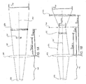
- Figure 1A shows a schematic representation of a non-contact thermometer device 100 and its optical profile 110 with reference to two target objects 121, 121.
- the device 100 generally includes a detector 130 and an objective lens system 140 arranged about an optical axis 145 such that the lens 140 can direct scene information (usually in the form of infrared radiation) from a target scene or object onto the detector 130.
- the device shown in Figure 1A has been configured in what will be referred to here as a "standard focus" arrangement. In such an arrangement, the measurement spot size (S SF ) increases or remains constant as the distance (D) from the objective lens 140 increases.
- S SF measurement spot size
- the spot size S SF In non-contact temperature measurement, it is desirable for the spot size S SF to fit the desired measurement zone or object as closely as possible.
- the spot size S SF at distance D OBJ2 from the device 100 closely fits the second object 122 as indicated by the optical profile 110.
- a close fit can provide a more accurate reading of the temperature of the target object 122 because the amount of non-target scene radiation imaged to the detector 120 is minimized.
- a measurement of the temperature of the smaller first object 121 at distance D OBJ1 from the lens 140 includes extraneous scene data which can throw off the temperature calculation produced by the device 100.
- Figure 1B shows a non-contact thermometer device 102 having a "close focus" optical profile 112.
- the detector 132 and objective lens system 142 are arranged such that the spot size S CF decreases to a minimum spot size S CF , MIN within a focus plane 160 at a distance D FP from the lens 142. Beyond this distance D FP , the spot size S F increases causing the close focus optical profile 112 to exhibit the "bow tie" shape commonly known in the art.
- a close focus optical profile 112 can provide a close fit for certain objects, while providing an inadequate fit for other objects.
- the optical profile 112 provides a well fit measurement spot size for the first object 121 at distance D OBJ1 from the lens 142, and measurement spot size that is too small for the second object 122 at distance D OBJ2 from the lens 142.
- Embodiments of the invention comprise a non-contact thermometer which simultaneously provides a plurality of optical profiles.
- Multiple optical profile devices according to the invention can provide readings from multiple, differently-sized measurement zones at substantially any given distance from the objective lens.
- embodiments of the invention can be used to provide a best-fit optical target for a range of applications and over a range of distances without the need to switch between modes.
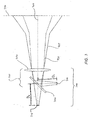
- FIG. 2 shows a schematic representation of such a temperature measurement device 200 according to some embodiments of the invention.
- the device 200 generally includes at least two detectors 210, 215 fixedly positioned relative to an optical system 220 which is configured to provide a different optical profile 230, 235 for each detector 210, 215.
- each detector 210, 215 receives scene data from a different measurement zone having a different spot size.
- the first detector 210 receives infrared radiation from the first measurement zone having a spot size S CF
- the second detector 215 receives infrared radiation from the second measurement zone having a spot size S SF .
- the first and second detectors 210, 215 simultaneously receive scene data and generate first and second signals 240, 245 corresponding to the sensed scene information. Each signal can then be processed to provide information about each measurement zone such as, for example, average zone temperature.
- embodiments of the schematic representation shown in Figure 2 can be installed within a device housing including components to provide a portable, hand-held non-contact temperature measurement device.
- first and second detectors 210, 215 are both detectors capable of collecting radiation in the infrared range of the electromagnetic spectrum, for example infrared thermal detectors.
- detectors e.g. photon detectors
- the detectors 210, 215 are fixed within the device 200 to provide a more durable device having fewer moving and moveable parts, but the size and positioning of the detectors depends on the characteristics of the optical system.
- the detectors are generally circular having a diameter of 0.5 mm to 2 mm. However detectors of any size and shape should be considered within the scope of the invention.
- Each detector produces a signal 240, 245 as a function of the radiation or other scene data imaged thereupon. These signals can be processed by known methods to indicate a temperature or other metric indicated via the received radiation.
- Embodiments of optical systems 220 generally include an objective lens system 250, and a specific detector arrangement relative to an optical axis 260 of the objective lens system 250.
- the optical system 220 further includes a beam splitter 270 or mirror system for directing the incoming radiation to the arrangement of detectors.
- the elements of the optical system 220 present to each detector 210, 215 a different optical profile 230, 235 that simultaneously provides for extracting a reading from multiple zones of the target scene 237. Because of the simultaneous presentation of multiple measurement zones, embodiments of the invention provide a single device, having no moving parts that can be used for both multiple and varying measurement applications without requiring the device to be reconfigured.
- the objective lens system 250 provides the image scene to the device 200.
- the objective lens system 250 comprises a single lens positioned within an aperture of the device housing.
- Other lens systems may include multiple lenses.
- the lenses of the lens system can be concave, convex, or otherwise shaped and can comprise glass, plastic, or other IR transparent materials. While the embodiments shown generally indicate a refractive objective lens system, other objective lens systems (e.g. a reflective system incorporating one or more mirrors to collect the radiation) are within the scope of the invention.
- the lens system can be focusable, allowing for adjustment of the focus plane in close focus systems and fine tuning (e.g. narrowing or widening of the optical profile) of distant focus systems.
- the optical system 220 of the embodiment shown in Figure 2 includes a beam splitter 270 and provides a device having simultaneous close focus and distant focus functionality.
- the beam splitter 270 is positioned on and angled relative to the optical axis 260 such that a portion of the IR radiation entering the device 200 is reflected onto the first detector 210.
- the unreflected portion of the IR radiation passes through the beam splitter 270 and onto the second detector 215 which has been positioned generally concentrically about the optical axis 260.
- the beam splitter 270 has been oriented at approximately 45 degrees relative to the optical axis 260 causing the first detector 210 to be positioned approximately 90 degrees relative to the optical axis 260.
- Beam splitter 270 can comprise any of a variety of beam splitters known in the art.
- the beam splitter 270 can be a silicon mirror coated to have a transmissivity of approximately 50% in the IR range.
- the optical system 220 further includes the specific positioning and arrangement of the detectors.
- the detectors 210, 215 are generally the same size, but are positioned at different fixed distances D 1 , D 2 from the beam splitter 270, and therefore the objective lens system 250.
- D 1 has been selected such that the first detector 210 provides close focus functionality.
- D 2 has been selected such that the second detector 215 provides distant focus functionality.
- Figures 6A and 6B depict measurement zone patterns at various distances from the objective lens 250. The pattern of Figure 6A is representative of the measurement zones at D FP .
- first measurement zone 610 is shown generally concentrically oriented about the optical axis 605, which projects through the page in this view. At this distance, the first, smaller zone 610 is contained entirely within and is generally concentric with the second measurement zone 612. In this optical system orientation, second measurement zone 612 is inclusive of first measurement zone 610, however, in some embodiments signal processing or logic can be used to provide exclusive measurements from each zone.
- Figure 6B represents a measurement zone pattern further from or closer to the objective lens 250, for example, at D TS .
- the configuration of the measurement zones can be seen to be generally the same as that of Figure 6A with first and second zones 620, 622 concentrically disposed about optical axis 605. However, here first measurement zone 620 is significantly larger relative to second measurement zone 622.
- Figure 3 shows an embodiment of a device 300 with an optical system 320 having detectors 310, 315 similarly arranged as in Figure 2 .
- the first and second detectors 310, 315 are of different size; namely the second detector 315 has a larger active range than the first detector 310.
- both detectors are positioned to provide the same focus functionality (here standard focus), but with different sized measurement zones as indicated along the optical profiles 330, 335.
- the measurement zone pattern at any given distance from the lens can correspond to that shown in Figure 6A or 6B depending on the size ratio between the detectors.
- embodiments including detectors having differently sized active ranges can also be arranged to provide close focus functionality.
- embodiments including both close and standard focus functionality can include detectors of different sizes. In such case, either of the close or standard focus detectors can be the larger detector.
- Some embodiments such as the device 400 of Figure 4 , have an optical system 420 that does not include a beam splitter.
- the provision of multiple and different optical profiles is accomplished by positioning the detectors in a different arrangement relative to the objective lens system 450.
- the first detector 410 is placed on the optical axis 460 at a distance D 1 from the objective lens system 450.
- the second detector 415 is likewise positioned on the optical axis 460, but at a distance D 2 from the objective lens system 450.
- D 2 is greater than D 1 such that D 2 provides for standard focus functionality to the second detector 415 and D 1 provides for close focus functionality from the first detector 410.
- the distances D 1 and D 2 can be selected to provide any other combination of focus arrangements (for example, two close focus profiles, one being near focus, and one being distant focused).
- the first detector 410 is within the optical channel 435 of the second detector 415, a portion of the radiation entering the device 400 may not reach the second detector 415.
- the measurement zone of the first detector is commensurate with the first measurement zone 610 of Figure 6A
- the second measurement zone 612 may have reduced sensitivity, especially in regions corresponding to the positioning of the first detector within the optical channel.
- One of skill in the art will recognize various arrangements for positioning the first detector 410 within the second optical channel 435 with minimal interference to the second detector 415.
- some embodiments include a "spider" arrangement, wherein the first detector is suspended in position by one or more thin wires or rods.
- the shadow of the mounting mechanism holding the detector in position can be minimized.
- the detectors 410, 415 can include detectors having different active ranges or sizes.
- the first detector can be smaller than the second detector.
- Figure 4 illustrates how a device having both a close focus optical profile 430 and standard focus optical profile 435 can be used to select a best fit optical profile for taking a particular reading.
- a small object 439 has been positioned at a distance D FP from the objective lens system 450.
- the standard focus measurement spot size as indicated by optical profile 435 is larger than the object 439.
- the close focus measurement zone 430 can be seen to better match the size and profile of the object 439.
- the close focus reading can represent a more accurate determination of the temperature of the targeted object 439.
- the close focus measurement zone is much too large due to the characteristic bow-tie shape of the close focus optical profile 430.
- the standard focus arrangement 435 causes a much more gradual increase in the measurement spot size as the distance D from the objective lens 450 increases. Accordingly, the standard focus arrangement generally provides a better fit measurement zone for objects 437 further from the device.
- Figure 4 further indicates that some embodiments include a crossover point 438 at some distance D C from the lens 450.
- a crossover point can occur in devices having any combination of optical profiles.
- the initially narrower profile close focus profile 430 begins to widen after the focus plane distance D FP , such that after the crossover distance D C , it is wider than the initially broader standard focus profile 435.
- the embodiment of Figure 2 would have a crossover point located at a distance off of the right side of the page.
- embodiments of the invention provide a device having multiple measurement spot sizes at substantially any given distance from the lens.
- the term "substantially,” in this context, should be understood to mean any distance from the lens with the exception of crossover points.
- a crossover point in embodiments including a crossover point, one should take care to select optics such that the crossover point occurs at a non-critical or generally undesirable measurement distance. For example, in devices with contemplated measurement distances from 10 to 100 inches, a crossover point should be selected at a distance of less than 10 inches or greater-than 100 inches.
- Figure 5 shows another schematic of a device 500 according to an embodiment that does not include a beam splitter.
- the detectors 510, 515 are positioned at different distances D 1 , D 2 and both are offset from the optical axis 560.
- the first and second optical profiles 530, 535 are offset from the optical axis 560 along its length.
- the resultant measurement zone pattern corresponds generally with that shown in Figure 6C where both the first measurement zone 630 and second measurement zone 632 are offset from the optical axis 605.
- One difference between this embodiment and that of Figure 4 that should be pointed out is that here, neither detector resides within the optical channel of the other. Thus, each detector receives a complete, unobstructed image of the target scene or object 537.
- the detector distances D 1 , D 2 could be the same, or differently arranged so as to provide for, as an example, two offset standard focus profiles.
- the detectors can be sized differently, offset in larger or smaller amounts from the optical axis, or.offset horizontally and or vertically from the optical axis. The detectors need not be offset the same amount from the optical axis or remain generally perpendicular to the axis as do the detectors shown in Figure 5 .
- devices according to the invention can include a specialized detector having multiple detector zones.
- Figure 7 shows a top plan view of such a detector.
- the detector 700 includes at least two detector regions 710, 715 each region comprising a single device and being capable of producing a signal representative of the IR radiation received across the device surface.
- the detector includes an inner region 710 and a concentric outer region 715.
- the optical profiles 830, 835 corresponding with each detector region can be seen in the schematic of Figure 8 with respect to device 800.
- the detector 700 is oriented relative to the objective lens system 850 such that each detector region provides standard focus functionality.
- the resultant effect of using a detector such as that of Figure 7 is an optical profile similar to that of Figure 3 , where two different sized detectors were positioned equidistant from the lens system.
- Specialized detectors can provide detector regions of varying shape and can thus be designed for use with a variety of applications.
- any of the above embodiments can be adapted to include more than two detectors.
- embodiments including a beam splitter can include a rotating mirror configured to direct image radiation upon a plurality of detectors fixed at angles relative to the optical axis. Such a system can be calibrated to take time multiplexed readings of the image scene.
- Embodiments not including a beam splitter can include a plurality of detectors arranged about and offset from the optical axis to provide any number of simultaneous measurement zones. Such systems can be specifically designed for particular applications and target objects.
- Embodiments can include sighting means for determining where the measurement zones are located relative to the target scene or object.
- the sighting means can include any means for indicating the size of one or more of the measurement spots in context so that a user can properly aim the device.
- Examples of sighting means include means which project an indicator onto the target scene, means which present an intermediate visual indicator between the device and target, and overlay means.
- Projected indicator means can include, for example, laser sighting as commonly known and used in the art.
- the multiple measurement zones can be indicated by projecting visible laser energy onto the object itself.
- a crosshair laser pattern can be projected for close focus and a border pattern can be projected for standard focus.
- Other projected indicators can include a visual light beam pattern filling the measurement zone(s).
- Intermediate visual indicator means can include, for example, a reticle or other scope on the device. Such an example can be thought of as similar to a rifle scope, wherein a user can look through or around the intermediate visual indicator means and view the target scene with the indicator in the foreground identifying the measurement zone(s).
- Overlay sighting means can include, for example, a video overlay system as known in the art.
- a video overlay system is described in commonly owned U.S. Patent Application Number 2006/0152737 .
- the device includes a visual light camera and video monitor for displaying a visual representation of the target scene.
- Software instructions are used to position a pattern overlay on the video image of the target scene that corresponds with the measurement zone.
- a processor and instruction set may need to be provided to calculate the appropriate size and positioning of the overlay on the scene image.
- such methods may require a laser or other distance measurement technique for determining the distance from the objective lens to the target scene.
- the detectors and optical system of devices can be installed within a device housing.
- the non-contact temperature measuring device is a hand-held device.
- a housing for such a device is suitably sized and includes features such as, for example, a grip or handle, so as to be readily held and maneuvered by a user.
- a device housing should include appropriate mounting facilities to position the detectors and components of the optical system according to the requirements of the optical system.
- some devices include analog and/or digital components to provide for local processing and display of the signals produced by the detectors.
- the housing may further include a trigger or other buttons for capturing a temperature reading or activating other functions.
- embodiments including a sighting means can include components specific to the sighting mechanism, such as an LCD display, laser sources, or reticles.
- devices according to the invention can be portable, such devices including a battery housing or other portable power source.
- embodiments of the invention can be non-portable. Such devices can be installed within other devices or part of larger a larger system requiring non-contact temperature measurements. For example, embodiments of the invention can be fixed relative to a belt or assembly line for taking optical readings of properties of objects thereon.
Landscapes
- Physics & Mathematics (AREA)
- General Physics & Mathematics (AREA)
- Spectroscopy & Molecular Physics (AREA)
- Radiation Pyrometers (AREA)
Abstract
Description
- This disclosure generally relates to non-contact temperature measurement and more particularly relates to non-contact temperature measurement with infrared spot detectors.
- Non-contact temperature-measuring devices, as they are known in the art, usually comprise an infrared detector for receiving infrared radiation emanating from a measurement spot or zone on an object of measurement, an optical system for imaging the infrared radiation emanating from the measurement spot onto the detector, and a sighting arrangement for identifying the position and size of the measurement zone on the object of measurement. A further processing arrangement which converts the infrared detector signal into a temperature indication is also usually connected to the detector.
- In many such devices, the optical system is designed so that only infrared radiation from a measurement spot or zone within the target scene or object of measurement is focused onto the detector at a given measurement distance. In most cases the measurement zone is defined as the area from which a large portion (greater than 50% and typically 90% or more) of the infrared rays focused onto the detector strike. Infrared spot detectors are useful for measuring the average temperature of the area of the measurement zone, but are generally not able to resolve separate temperature zones within the measurement zone.
- The size of the measurement zone usually varies with the measurement distance from the measuring device to the target scene or object. This variation in measurement zone size can be referred to as the optical profile and generally depends upon the design of the optical system. Examples of commonly used measurement profiles include standard focus and close focus measurement profiles. For the purposes of this disclosure the term "standard focus" will refer to a measurement profile similar to that shown in
Figure 1A , i.e. where the measurement spot size is constant or increases as the distance from the objective lens increases. The term "close focus" will refer to a measurement profile similar to that ofFigure 1B , i.e. exhibiting a "bow-tie" shape. A close focus profile can be a "near focus" profile having a minimum measurement zone size at a distance of less than one half meter from the lens or a "distant focus" profile having a minimum measurement zone size at a distance of one half meter or greater from the lens. Both close focus and standard focus optical systems are useful in practical applications and non-contact temperature measurement devices are available for each and at a variety of near or distant ranges. - In applications where spot temperatures must be measured at a number of distances it may be desirable to focus the scene image in order to provide a minimal measurement zone size at multiple distances. Similarly, in applications where multiple objects of different sizes are to be measured at the same distance, it is desirable to have multiple measurement zone sizes at that distance to provide a closer fit to each object. Having both a standard focus device and a close focus device can be useful in such situations, however the added cost of a second device often precludes its purchase. In some instances, a single device with focusable optics can be used to overcome the issues of different measurement distances and object sizes, however the ability to adjust a device's optical system can significantly add to the cost of such a device. Similarly, devices which include a single detector moveable relative to the optical system in order to change the device's optical profile are often undesirable because they are more susceptible to breaking and more expensive than fixed position devices. Moreover, in many measurement applications, continuous adjustability is unnecessary because the variations in distance and object size are often discrete. Other difficulties with non-contact temperature measurement that embodiments of the invention address will become apparent throughout the following description.
- A multizone, non-contact spot measurement device is disclosed. Non-contact measurement devices include two or more fixed detectors for sensing scene data from corresponding measurement zones within a target scene and generating signals in response to the sensed data. An optical system of the device including an objective lens system images the scene data onto the detectors such that each detector is provided with a different optical profile. That is, at substantially any given distance from the objective lens system, each measurement zone is different from the other measurement zones of the device. Devices can include close focus optical profiles, standard focus optical profiles, or one or more of both close and standard focus optical profiles. Optical systems can include the positioning and arrangement of the detectors, and in some embodiments, a beam splitter. In some embodiments, the detectors are infrared detectors, the device corresponding to a thermometer. Embodiments of the invention can further include a hand-held housing and sighting means.
- In another aspect, embodiments of the invention include a device for infrared temperature measurement having a single specialized detector. Such specialized detectors can have at least two distinct detector regions, each region receiving infrared radiation from a target scene according to different optical profiles. Embodiments according to this aspect include an optical system for imaging target scene radiation according to the different optical profiles onto each region of the specialized detector.
- Embodiments of the invention thus provide a device for simultaneous, non-contact temperature measurement of multiple zones of a target scene. Such devices eliminate the need for a user to own multiple non-contact measurement devices for measuring different objects within a scene or objects at different distances. Moreover, embodiments of the invention provide this functionality with fixed detectors, eliminating the cost and fragility associated with moveable detector devices.
- The following drawings are illustrative of particular embodiments of the invention and therefore do not limit the scope of the invention. The drawings are not to scale (unless so stated) and are intended for use in conjunction with the explanations in the following detailed description. Embodiments of the invention will hereinafter be described in conjunction with the appended drawings, wherein like numerals denote like elements.
-
Figure 1A shows a schematic representation of a standard focus device. -
Figure 1B shows a schematic representation of a close focus device. -
Figure 2 shows a schematic representation of a device for temperature measurement according to some embodiments of the invention. -
Figure 3 shows a schematic representation of a device for temperature measurement according to some embodiments of the invention. -
Figure 4 is shows a schematic representation of a device for temperature measurement according to some embodiments of the invention. -
Figure 5 is shows a schematic representation of a device for temperature measurement according to some embodiments of the invention. -
Figures 6A-6C show multiple measurement zones according to some embodiments of the invention. -
Figure 7 shows a representation of an infrared spot detector with multiple regions according to some embodiments of the invention. -
Figure 8 shows a schematic representation of a device for temperature measurement including the detector ofFigure 7 according to some embodiments of the invention. - The following detailed description should be read with reference to the drawings, in which like elements in different drawings are numbered identically. It will be understood that embodiments shown in the drawings and described herein are merely for illustrative purposes and are not intended to limit the invention to any embodiment. On the contrary, it is intended to cover alternatives, modifications, and equivalents as may be included within the scope of the invention as defined by the appended claims.
- Non-contact thermometers can be used to determine a temperature reading from a target scene or object by sensing radiation from the object. For example,
Figure 1A shows a schematic representation of anon-contact thermometer device 100 and itsoptical profile 110 with reference to twotarget objects device 100 generally includes adetector 130 and anobjective lens system 140 arranged about anoptical axis 145 such that thelens 140 can direct scene information (usually in the form of infrared radiation) from a target scene or object onto thedetector 130. The device shown inFigure 1A , has been configured in what will be referred to here as a "standard focus" arrangement. In such an arrangement, the measurement spot size (SSF) increases or remains constant as the distance (D) from theobjective lens 140 increases. In non-contact temperature measurement, it is desirable for the spot size SSF to fit the desired measurement zone or object as closely as possible. For example, the spot size SSF at distance DOBJ2 from thedevice 100 closely fits thesecond object 122 as indicated by theoptical profile 110. A close fit can provide a more accurate reading of the temperature of thetarget object 122 because the amount of non-target scene radiation imaged to the detector 120 is minimized. By contrast, a measurement of the temperature of the smallerfirst object 121 at distance DOBJ1 from thelens 140, for example, includes extraneous scene data which can throw off the temperature calculation produced by thedevice 100. -
Figure 1B shows anon-contact thermometer device 102 having a "close focus"optical profile 112. In thisdevice 102, thedetector 132 andobjective lens system 142 are arranged such that the spot size SCF decreases to a minimum spot size SCF, MIN within afocus plane 160 at a distance DFP from thelens 142. Beyond this distance DFP, the spot size SF increases causing the close focusoptical profile 112 to exhibit the "bow tie" shape commonly known in the art. Devices using a close focus arrangement can be near focus devices (i.e. DFP < one half meter) or distant focus devices (i.e. DFP >= one half meter). As shown inFigure 1B , a close focusoptical profile 112 can provide a close fit for certain objects, while providing an inadequate fit for other objects. For example, theoptical profile 112 provides a well fit measurement spot size for thefirst object 121 at distance DOBJ1 from thelens 142, and measurement spot size that is too small for thesecond object 122 at distance DOBJ2 from thelens 142. - Embodiments of the invention comprise a non-contact thermometer which simultaneously provides a plurality of optical profiles. Multiple optical profile devices according to the invention can provide readings from multiple, differently-sized measurement zones at substantially any given distance from the objective lens. Thus, embodiments of the invention can be used to provide a best-fit optical target for a range of applications and over a range of distances without the need to switch between modes.
-
Figure 2 shows a schematic representation of such atemperature measurement device 200 according to some embodiments of the invention. Thedevice 200 generally includes at least twodetectors 210, 215 fixedly positioned relative to anoptical system 220 which is configured to provide a differentoptical profile detector 210, 215. Thus, at substantially any given distance eachdetector 210, 215 receives scene data from a different measurement zone having a different spot size. For example, with respect to targetscene 237 at distance DTS, the first detector 210 receives infrared radiation from the first measurement zone having a spot size SCF, and thesecond detector 215 receives infrared radiation from the second measurement zone having a spot size SSF. In such adevice 200, the first andsecond detectors 210, 215 simultaneously receive scene data and generate first andsecond signals 240, 245 corresponding to the sensed scene information. Each signal can then be processed to provide information about each measurement zone such as, for example, average zone temperature. In application, embodiments of the schematic representation shown inFigure 2 can be installed within a device housing including components to provide a portable, hand-held non-contact temperature measurement device. - In some embodiments, first and
second detectors 210, 215 are both detectors capable of collecting radiation in the infrared range of the electromagnetic spectrum, for example infrared thermal detectors. One of skill in the art will recognize that other detectors (e.g. photon detectors) can be used, and can be used in combination with one or more infrared detectors. Thedetectors 210, 215 are fixed within thedevice 200 to provide a more durable device having fewer moving and moveable parts, but the size and positioning of the detectors depends on the characteristics of the optical system. In some embodiments, the detectors are generally circular having a diameter of 0.5 mm to 2 mm. However detectors of any size and shape should be considered within the scope of the invention. Each detector produces asignal 240, 245 as a function of the radiation or other scene data imaged thereupon. These signals can be processed by known methods to indicate a temperature or other metric indicated via the received radiation. - Embodiments of
optical systems 220 according to the invention generally include anobjective lens system 250, and a specific detector arrangement relative to anoptical axis 260 of theobjective lens system 250. In some embodiments, theoptical system 220 further includes abeam splitter 270 or mirror system for directing the incoming radiation to the arrangement of detectors. In combination, the elements of theoptical system 220 present to each detector 210, 215 a differentoptical profile target scene 237. Because of the simultaneous presentation of multiple measurement zones, embodiments of the invention provide a single device, having no moving parts that can be used for both multiple and varying measurement applications without requiring the device to be reconfigured. - The
objective lens system 250 provides the image scene to thedevice 200. In some embodiments, theobjective lens system 250 comprises a single lens positioned within an aperture of the device housing. Other lens systems may include multiple lenses. The lenses of the lens system can be concave, convex, or otherwise shaped and can comprise glass, plastic, or other IR transparent materials. While the embodiments shown generally indicate a refractive objective lens system, other objective lens systems (e.g. a reflective system incorporating one or more mirrors to collect the radiation) are within the scope of the invention. In some embodiments, the lens system can be focusable, allowing for adjustment of the focus plane in close focus systems and fine tuning (e.g. narrowing or widening of the optical profile) of distant focus systems. - The
optical system 220 of the embodiment shown inFigure 2 includes abeam splitter 270 and provides a device having simultaneous close focus and distant focus functionality. Here, thebeam splitter 270 is positioned on and angled relative to theoptical axis 260 such that a portion of the IR radiation entering thedevice 200 is reflected onto the first detector 210. The unreflected portion of the IR radiation passes through thebeam splitter 270 and onto thesecond detector 215 which has been positioned generally concentrically about theoptical axis 260. In this embodiment, thebeam splitter 270 has been oriented at approximately 45 degrees relative to theoptical axis 260 causing the first detector 210 to be positioned approximately 90 degrees relative to theoptical axis 260.Beam splitter 270 can comprise any of a variety of beam splitters known in the art. For example, thebeam splitter 270 can be a silicon mirror coated to have a transmissivity of approximately 50% in the IR range. - The
optical system 220 further includes the specific positioning and arrangement of the detectors. In the embodiment ofFigure 2 , thedetectors 210, 215 are generally the same size, but are positioned at different fixed distances D1, D2 from thebeam splitter 270, and therefore theobjective lens system 250. As can be seen by following the optical profile of thefirst detector 230, D1 has been selected such that the first detector 210 provides close focus functionality. Conversely, as is apparent by following the secondoptical profile 235, D2 has been selected such that thesecond detector 215 provides distant focus functionality.Figures 6A and 6B depict measurement zone patterns at various distances from theobjective lens 250. The pattern ofFigure 6A is representative of the measurement zones at DFP. Here,first measurement zone 610 is shown generally concentrically oriented about theoptical axis 605, which projects through the page in this view. At this distance, the first,smaller zone 610 is contained entirely within and is generally concentric with thesecond measurement zone 612. In this optical system orientation,second measurement zone 612 is inclusive offirst measurement zone 610, however, in some embodiments signal processing or logic can be used to provide exclusive measurements from each zone.Figure 6B represents a measurement zone pattern further from or closer to theobjective lens 250, for example, at DTS. Here, the configuration of the measurement zones can be seen to be generally the same as that ofFigure 6A with first andsecond zones optical axis 605. However, herefirst measurement zone 620 is significantly larger relative tosecond measurement zone 622. -
Figure 3 shows an embodiment of adevice 300 with anoptical system 320 havingdetectors Figure 2 . However, in this embodiment, the first andsecond detectors second detector 315 has a larger active range than thefirst detector 310. Additionally, here bothdetectors objective lens system 350, that is D1 = D2. Thus, both detectors are positioned to provide the same focus functionality (here standard focus), but with different sized measurement zones as indicated along theoptical profiles Figure 6A or 6B depending on the size ratio between the detectors. One should appreciate that embodiments including detectors having differently sized active ranges can also be arranged to provide close focus functionality. Moreover, embodiments including both close and standard focus functionality can include detectors of different sizes. In such case, either of the close or standard focus detectors can be the larger detector. - Some embodiments, such as the
device 400 ofFigure 4 , have anoptical system 420 that does not include a beam splitter. Here, the provision of multiple and different optical profiles is accomplished by positioning the detectors in a different arrangement relative to theobjective lens system 450. In this embodiment, for example, thefirst detector 410 is placed on theoptical axis 460 at a distance D1 from theobjective lens system 450. Thesecond detector 415 is likewise positioned on theoptical axis 460, but at a distance D2 from theobjective lens system 450. In this embodiment, D2 is greater than D1 such that D2 provides for standard focus functionality to thesecond detector 415 and D1 provides for close focus functionality from thefirst detector 410. Of course, the distances D1 and D2 can be selected to provide any other combination of focus arrangements (for example, two close focus profiles, one being near focus, and one being distant focused). Here, it should be recognized that because thefirst detector 410 is within theoptical channel 435 of thesecond detector 415, a portion of the radiation entering thedevice 400 may not reach thesecond detector 415. Thus, while the measurement zone of the first detector is commensurate with thefirst measurement zone 610 ofFigure 6A , at certain distances from theobjective lens 450 thesecond measurement zone 612 may have reduced sensitivity, especially in regions corresponding to the positioning of the first detector within the optical channel. One of skill in the art will recognize various arrangements for positioning thefirst detector 410 within the secondoptical channel 435 with minimal interference to thesecond detector 415. For example, some embodiments include a "spider" arrangement, wherein the first detector is suspended in position by one or more thin wires or rods. Thus, the shadow of the mounting mechanism holding the detector in position can be minimized. It should also be mentioned that as in embodiments described above, thedetectors - Additionally,
Figure 4 illustrates how a device having both a close focusoptical profile 430 and standard focusoptical profile 435 can be used to select a best fit optical profile for taking a particular reading. Here asmall object 439 has been positioned at a distance DFP from theobjective lens system 450. At this location, the standard focus measurement spot size as indicated byoptical profile 435 is larger than theobject 439. Thus, a standard focus measurement of this object at this location would include extraneous information that could affect the accuracy of the reading. The closefocus measurement zone 430, however, can be seen to better match the size and profile of theobject 439. Thus in this case, the close focus reading can represent a more accurate determination of the temperature of the targetedobject 439. By contrast, with respect to object/target scene 437 at a distance DTS from theobjective lens 450, the close focus measurement zone is much too large due to the characteristic bow-tie shape of the close focusoptical profile 430. However, thestandard focus arrangement 435 causes a much more gradual increase in the measurement spot size as the distance D from theobjective lens 450 increases. Accordingly, the standard focus arrangement generally provides a better fit measurement zone forobjects 437 further from the device. By simultaneously providing both close and standard focus functionality, devices according to embodiments of the invention can allow the user to select which reading to utilize to take a reading that best fits the object being tested and minimizes inclusion of extraneous or background scene information. Moreover, some devices can include control circuitry or software to automatically selects the better fit reading for temperature determination and presents indicates the more appropriate reading. -
Figure 4 further indicates that some embodiments include acrossover point 438 at some distance DC from thelens 450. A crossover point can occur in devices having any combination of optical profiles. In this example, the initially narrower profileclose focus profile 430 begins to widen after the focus plane distance DFP, such that after the crossover distance DC, it is wider than the initially broaderstandard focus profile 435. As another example, the embodiment ofFigure 2 would have a crossover point located at a distance off of the right side of the page. As previously described, embodiments of the invention provide a device having multiple measurement spot sizes at substantially any given distance from the lens. Thus, the term "substantially," in this context, should be understood to mean any distance from the lens with the exception of crossover points. For this reason, in embodiments including a crossover point, one should take care to select optics such that the crossover point occurs at a non-critical or generally undesirable measurement distance. For example, in devices with contemplated measurement distances from 10 to 100 inches, a crossover point should be selected at a distance of less than 10 inches or greater-than 100 inches. -
Figure 5 shows another schematic of adevice 500 according to an embodiment that does not include a beam splitter. Here, thedetectors optical axis 560. As a result, the first and secondoptical profiles optical axis 560 along its length. Thus, the resultant measurement zone pattern corresponds generally with that shown inFigure 6C where both thefirst measurement zone 630 andsecond measurement zone 632 are offset from theoptical axis 605. One difference between this embodiment and that ofFigure 4 that should be pointed out is that here, neither detector resides within the optical channel of the other. Thus, each detector receives a complete, unobstructed image of the target scene orobject 537. Of course, one should recognize numerous variations and combinations of the offset configuration shown. For example, the detector distances D1, D2 could be the same, or differently arranged so as to provide for, as an example, two offset standard focus profiles. Additionally, the detectors can be sized differently, offset in larger or smaller amounts from the optical axis, or.offset horizontally and or vertically from the optical axis. The detectors need not be offset the same amount from the optical axis or remain generally perpendicular to the axis as do the detectors shown inFigure 5 . - In other embodiments, devices according to the invention can include a specialized detector having multiple detector zones.
Figure 7 shows a top plan view of such a detector. As can be seen from this view, thedetector 700 includes at least twodetector regions Figure 7 , the detector includes aninner region 710 and a concentricouter region 715. Theoptical profiles 830, 835 corresponding with each detector region can be seen in the schematic ofFigure 8 with respect todevice 800. In this arrangement, thedetector 700 is oriented relative to the objective lens system 850 such that each detector region provides standard focus functionality. The resultant effect of using a detector such as that ofFigure 7 is an optical profile similar to that ofFigure 3 , where two different sized detectors were positioned equidistant from the lens system. Specialized detectors can provide detector regions of varying shape and can thus be designed for use with a variety of applications. - It should be recognized that any of the above embodiments can be adapted to include more than two detectors. For example, embodiments including a beam splitter can include a rotating mirror configured to direct image radiation upon a plurality of detectors fixed at angles relative to the optical axis. Such a system can be calibrated to take time multiplexed readings of the image scene. Embodiments not including a beam splitter can include a plurality of detectors arranged about and offset from the optical axis to provide any number of simultaneous measurement zones. Such systems can be specifically designed for particular applications and target objects.
- Embodiments can include sighting means for determining where the measurement zones are located relative to the target scene or object. The sighting means can include any means for indicating the size of one or more of the measurement spots in context so that a user can properly aim the device. Examples of sighting means include means which project an indicator onto the target scene, means which present an intermediate visual indicator between the device and target, and overlay means.
- Projected indicator means can include, for example, laser sighting as commonly known and used in the art. In such embodiment, the multiple measurement zones can be indicated by projecting visible laser energy onto the object itself. For example, a crosshair laser pattern can be projected for close focus and a border pattern can be projected for standard focus. Other projected indicators can include a visual light beam pattern filling the measurement zone(s).
- Intermediate visual indicator means can include, for example, a reticle or other scope on the device. Such an example can be thought of as similar to a rifle scope, wherein a user can look through or around the intermediate visual indicator means and view the target scene with the indicator in the foreground identifying the measurement zone(s).
- Overlay sighting means can include, for example, a video overlay system as known in the art. One example of a video overlay system is described in commonly owned
U.S. Patent Application Number 2006/0152737 . In such a system, the device includes a visual light camera and video monitor for displaying a visual representation of the target scene. Software instructions are used to position a pattern overlay on the video image of the target scene that corresponds with the measurement zone. In such embodiments, a processor and instruction set may need to be provided to calculate the appropriate size and positioning of the overlay on the scene image. In addition, such methods may require a laser or other distance measurement technique for determining the distance from the objective lens to the target scene. - The detectors and optical system of devices according to embodiments of the invention can be installed within a device housing. In some embodiments, the non-contact temperature measuring device is a hand-held device. A housing for such a device is suitably sized and includes features such as, for example, a grip or handle, so as to be readily held and maneuvered by a user. A device housing should include appropriate mounting facilities to position the detectors and components of the optical system according to the requirements of the optical system. In addition, some devices include analog and/or digital components to provide for local processing and display of the signals produced by the detectors. The housing may further include a trigger or other buttons for capturing a temperature reading or activating other functions. And embodiments including a sighting means, such as those described above, can include components specific to the sighting mechanism, such as an LCD display, laser sources, or reticles. Moreover, devices according to the invention can be portable, such devices including a battery housing or other portable power source.
- Additionally, embodiments of the invention can be non-portable. Such devices can be installed within other devices or part of larger a larger system requiring non-contact temperature measurements. For example, embodiments of the invention can be fixed relative to a belt or assembly line for taking optical readings of properties of objects thereon.
- Thus, embodiments of the multizone non-contact spot thermometer are disclosed. Although the present invention has been described in considerable detail with reference to certain disclosed embodiments, the disclosed embodiments are presented for purposes of illustration and not limitation and other embodiments of the invention are possible. One skilled in the art will appreciate that various changes, adaptations, and modifications may be made without departing from the spirit of the invention and the scope of the appended claims.
Claims (24)
- A non-contact measurement device comprising:a first detector for sensing scene data from a first measurement zone within a target scene and generating a first signal corresponding to the second data;a second detector for sensing scene data from a second measurement zone within the target scene and generating a second signal corresponding to the sensed data; andan optical system for imaging scene data from the target scene onto the detectors, the optical system comprising an objective lens system,wherein the optical system images the scene data from the first measurement zone onto the first detector and the scene data from the second measurement zone onto the second detector, andwherein he sizes of the first and second measurement zones vary with distance from the objective lens systems according to first and second optical profiles, such that at substantially any given distance from the objective lens system the first measurement zone size is different from the second measurement zone size.
- The device of claim 1, wherein one or more of the detectors are infrared (IR) detectors, for example thermal detectors or photon detectors.
- The device of claim 1 or claim 2, wherein the detectors are fixedly positioned within the device.
- The device of any one of the preceding claims, wherein the first and second detectors are of different sizes.
- The device of any one of the preceding claims, wherein the sensed data is infrared radiation.
- The device of any one of the preceding claims, wherein the first and second signals correspond to the temperature of the target scene within the first and second measurement zones, the device thus comprising a non-contact thermometer.
- The device of any one of the preceding claims, wherein the optical system further comprises a beam splitter positioned on an optical axis defined by the optical system and oriented to direct the scene data onto each of the detectors, the beam splitter preferably comprising a partially transmissive mirror angled relative to the optical axis, or a rotating mirror.
- The device of any one of claims 1 to 7, wherein the optical system further comprises positioning the detectors relative to the optical system and an optical axis defined by the optical system.
- The device of claim 8, wherein the detectors are positioned such that a central axis of each of the detectors is generally coaxial with the optical axis, each detector being positioned at a different distance from the optical system, or such that at least one detector is positioned such that a central axis of the detector passes through the optical system at an angle relative to the optical axis, or such that none of the central axes of the detectors are coaxial with the optical axis.
- The device of any one of the preceding claims, wherein the objective lens system is a refractive system comprising:one or m ore lenses; orone or more collecting mirrors.
- The device of any one of the preceding claims, wherein one or more of the optical profiles is a close focus optical profile or a standard focus optical profile.
- The device of any one of the preceding claims, further comprising:at least one additional detector for sensing scene data from an additional measurement zone within the target scene and generating an additional signal corresponding to the sensed data,wherein each additional detector is positioned relative to the optical system such that the optical system images the scene data from additional measurement zones onto each corresponding additional detector, and
wherein the sizes of the additional measurement zones vary with distance from the objective lens system according to additional corresponding optical profiles, such that at substantially any given distance from the objective lens system each measurement zone size is different from every other measurement zone size. - The device of any one of the preceding claims, further comprising a sighting means for identifying the position and size of the measurement zones within the target scene, for example a projected indicator sighting means, an intermediate visual sighting means, or an overlay sighting means.
- A non-contact temperature measurement device, comprising:a first infrared (IR) detector for sensing IR radiation from a first measurement spot within a target scene and generating a first signal corresponding to the sensed IR radiation;a second IR detector for sensing IR radiation from a second measurement spot within the target scene and generating a second signal corresponding to the sensed IR radiation; andan optical system for imaging IR radiation, wherein the optical system defines an optical axis and images the IR radiation from the first measurement spot onto the first IR detector and images the IR radiation from the second measurement spot onto the second IR detector, andwherein the optical system is configured to image a different optical profile to each IR detector, such that at substantially any given distance from the optical system the size of the first measurement spot does not equal the size of the second measurement spot.
- The device of claim 14, wherein the infrared detectors are thermal detectors.
- The device of claim 14 or claim 15, wherein the optical system comprises a beam splitter positioned on the optical axis and oriented to direct the IR radiation onto the first and second IR detectors.
- The device of any one of claims 14 to 16, wherein the first and second infrared detectors have different active diameters.
- The device of any one of claims 14 to 17, wherein at least one of the optical profiles is close focus or standard focus.
- The device of any one of claims 14 to 18, further comprising at least one additional detector.
- The device of any one of claims 14 to 19, wherein the measurement spots at least partially overlap one of the measurement spots preferably being entirely within another of the measurement spots, the measurement spots preferably being concentric.
- The device of any one of the preceding claims, wherein the device further comprises a hand-held housing, the detectors and optical system being coupled thereto.
- A hand-held device for infrared temperature measurement comprising:an infrared detector comprising (i) a first detector region for sensing infrared radiation from a first measurement zone within a target scene and generating a first signal corresponding to the sensed infrared radiation, and (ii) a second detector region for sensing infrared radiation from a second measurement zone within the target scene and generating a second signal corresponding to the sensed infrared radiation; andan optical system comprising an objective lens systems,wherein images the infrared radiation from the first measurement zone onto the first detector region and images the infrared radiation from the second measurement zone onto the second detector region, and
wherein the optical system is configured to image a different optical profile to each detector region, such that at substantially any given distance from the objective lens system the size of the first measurement zone does not equal the size of the second measurement zone. - The device of claim 22, wherein the first detector region is positioned completely within the second detector region.
- The device of claim 22, wherein the first measurement zone is central and concentric with the second measurement zone.
Applications Claiming Priority (1)
| Application Number | Priority Date | Filing Date | Title |
|---|---|---|---|
| US12/192,720 US8240912B2 (en) | 2008-08-15 | 2008-08-15 | Multi-zone non-contact spot thermometer |
Publications (2)
| Publication Number | Publication Date |
|---|---|
| EP2154500A2 true EP2154500A2 (en) | 2010-02-17 |
| EP2154500A3 EP2154500A3 (en) | 2010-03-31 |
Family
ID=41226334
Family Applications (1)
| Application Number | Title | Priority Date | Filing Date |
|---|---|---|---|
| EP09251968A Withdrawn EP2154500A3 (en) | 2008-08-15 | 2009-08-10 | Multi-zone non-contact spot thermometer |
Country Status (3)
| Country | Link |
|---|---|
| US (1) | US8240912B2 (en) |
| EP (1) | EP2154500A3 (en) |
| CN (1) | CN101706327B (en) |
Cited By (2)
| Publication number | Priority date | Publication date | Assignee | Title |
|---|---|---|---|---|
| EP3508793A1 (en) * | 2018-01-09 | 2019-07-10 | Safera OY | Stove guard using a broad field of view |
| CN112729551A (en) * | 2020-12-08 | 2021-04-30 | 福建星网天合智能科技有限公司 | Human body infrared temperature measurement method, distance compensation method and device |
Families Citing this family (8)
| Publication number | Priority date | Publication date | Assignee | Title |
|---|---|---|---|---|
| CN101922971B (en) * | 2010-05-06 | 2012-09-05 | 袁国炳 | Optical system for infrared radiation thermometer and focusing structure |
| DE102010030928A1 (en) * | 2010-07-05 | 2012-01-05 | Robert Bosch Gmbh | Non-contact measurement of a mean surface temperature of a measuring range |
| US8902302B2 (en) | 2011-09-16 | 2014-12-02 | Emerson Electric Co. | Method and apparatus for surveying with a feature location |
| CN103776548A (en) * | 2014-02-14 | 2014-05-07 | 丹纳赫(上海)工业仪器技术研发有限公司 | Infrared temperature measurement meter and method for measuring temperature of energy area |
| FI3589190T3 (en) | 2017-03-01 | 2023-03-25 | Thermidas Oy | Multimodal medical imaging and analyzing system, method and server |
| CN107560753B (en) * | 2017-09-28 | 2024-01-09 | 清华大学 | Vehicle wheel axle single-point temperature measurement device and method based on visible light and infrared multispectrum |
| CN108151887A (en) * | 2017-12-25 | 2018-06-12 | 湖南航天诚远精密机械有限公司 | A kind of microwave experiment stove |
| CN111024242A (en) * | 2019-12-13 | 2020-04-17 | 浙江大立科技股份有限公司 | Thermal infrared imager and continuous automatic focusing method thereof |
Family Cites Families (62)
| Publication number | Priority date | Publication date | Assignee | Title |
|---|---|---|---|---|
| GB696604A (en) | 1950-04-07 | 1953-09-02 | Leeds & Northrup Co | Improved optical systems for radiation pyrometers |
| DE1797032B2 (en) | 1968-08-07 | 1976-07-22 | Max-Planck-Gesellschaft zur Förderung der Wissenschaften e.V., 3400 Göttingen | COLOR TEMPERATURE MEASURING DEVICE |
| US4005605A (en) * | 1974-07-22 | 1977-02-01 | Mikron Instrument Company, Inc. | Remote reading infrared thermometer |
| JPS589928B2 (en) * | 1977-09-30 | 1983-02-23 | ミノルタ株式会社 | Steel camera with automatic and manual focus adjustment |
| GB1602160A (en) | 1978-04-26 | 1981-11-11 | Negretti & Zambra Aviat Ltd | Pyrometers |
| US4215273A (en) * | 1979-03-29 | 1980-07-29 | Nasa | Multispectral scanner optical system |
| JPS56501138A (en) | 1979-09-12 | 1981-08-13 | ||
| US4343182A (en) | 1980-07-14 | 1982-08-10 | Exergen Corporation | Radiation heat loss detector |
| JPS5722521A (en) | 1980-07-15 | 1982-02-05 | Horiba Ltd | Confirming method for radiation or irradiated area |
| US4315150A (en) | 1980-07-24 | 1982-02-09 | Telatemp Corporation | Targeted infrared thermometer |
| DE3213955A1 (en) | 1982-04-16 | 1982-10-14 | Dr. Herbert Specht VisIR-Messtechnik Handels GmbH, 6204 Taunusstein | Laser beam sighting device for marking the position and diameter of the measurement spot for radiation thermometers having focal and afocal lens and mirror optical systems |
| DE3403372C1 (en) | 1984-02-01 | 1985-07-25 | Fraunhofer-Gesellschaft zur Förderung der angewandten Forschung e.V., 8000 München | Multi-channel process spectrometer |
| US4948258A (en) * | 1988-06-27 | 1990-08-14 | Harbor Branch Oceanographic Institute, Inc. | Structured illumination surface profiling and ranging systems and methods |
| JPH081460Y2 (en) | 1990-05-23 | 1996-01-17 | 株式会社堀場製作所 | Radiation thermometer |
| FR2665533B1 (en) | 1990-08-06 | 1994-03-25 | Ortomedic | DEVICE FOR REMOTE MEASUREMENT OF TEMPERATURE AND / OR TEMPERATURE DIFFERENCES. |
| CA2093716C (en) | 1992-05-04 | 1999-08-17 | Thomas M. Sorensen | Movable heat treat apparatus with sighting means |
| US5399018A (en) | 1993-03-31 | 1995-03-21 | Omega Engineering, Inc. | Adjustable positioning housing assembly for an infrared thermocouple |
| US5481819A (en) | 1993-06-08 | 1996-01-09 | Teetzel; James W. | Laser module apparatus |
| US5368392B1 (en) | 1993-09-17 | 1998-11-03 | Omega Engineering | Method and apparatus for measuring temperature using infrared techniques |
| US5823679A (en) | 1993-09-17 | 1998-10-20 | Omega Engineering, Inc. | Method and apparatus for measuring temperature including aiming light |
| IL107659A0 (en) | 1993-11-18 | 1994-07-31 | State Of Israel Ministy Of Def | A hand-held infra red imaging probe |
| SE502278C2 (en) | 1994-01-21 | 1995-09-25 | Jonas Samuelsson | Device for measuring vehicle wheel angles |
| US5626424A (en) | 1994-07-21 | 1997-05-06 | Raytek Subsidiary, Inc. | Dual light source aiming mechanism and improved actuation system for hand-held temperature measuring unit |
| JP3708991B2 (en) | 1994-12-28 | 2005-10-19 | ペンタックス株式会社 | Inner focus telescope |
| US5653537A (en) * | 1995-03-17 | 1997-08-05 | Ircon, Inc. | Non-contacting infrared temperature thermometer detector apparatus |
| GB2303988A (en) * | 1995-07-31 | 1997-03-05 | Secr Defence | Thermal imaging system with detector array calibration mode |
| DE19528590C3 (en) | 1995-08-03 | 2003-11-27 | Raytek Gmbh | Temperature measuring device |
| US5628034A (en) | 1996-02-27 | 1997-05-06 | Eastman Kodak Company | Image recording apparatus with movement detector and laser emitter |
| IT1284119B1 (en) | 1996-07-05 | 1998-05-08 | Tecnica S R L | INFRARED THERMOMETER INCLUDING AN OPTICAL AIMING SYSTEM |
| US5836694A (en) | 1996-12-10 | 1998-11-17 | Raytek Subsidiary, Inc. | Laser and scope aiming mechanism for a hand-held temperature measuring unit |
| DE19654211C2 (en) | 1996-12-24 | 2000-07-06 | Leica Microsystems | Confocal microscope |
| DE19654276A1 (en) | 1996-12-24 | 1998-06-25 | Raytek Gmbh | Device for non-contact temperature measurement |
| US6012840A (en) * | 1997-01-27 | 2000-01-11 | The Regents Of The University Of California | Single-fiber multi-color pyrometry |
| US7353071B2 (en) | 1999-07-14 | 2008-04-01 | Philips Solid-State Lighting Solutions, Inc. | Method and apparatus for authoring and playing back lighting sequences |
| JP4187329B2 (en) | 1997-11-21 | 2008-11-26 | オメガ エンジニアリング,インコーポレイテッド | Emissivity display method using one-handed instrument and one-handed instrument equipped with emissivity display means |
| ATE248356T1 (en) | 1998-01-30 | 2003-09-15 | Tecnimed Srl | INFRARED THERMOMETER |
| DE19949582B4 (en) | 1998-10-14 | 2004-02-12 | Pentax Corp. | Auto focus device for a telescope |
| US6951411B1 (en) | 1999-06-18 | 2005-10-04 | Spectrx, Inc. | Light beam generation, and focusing and redirecting device |
| US6377400B1 (en) | 1999-07-02 | 2002-04-23 | Milton Bernard Hollander | Laser sighting beam modification for measuring or treatment instrument |
| CA2319880C (en) | 1999-09-17 | 2012-03-13 | Milton Bernard Hollander | Laser beam adjustment |
| AUPQ771700A0 (en) * | 2000-05-24 | 2000-06-15 | Bartsch, Friedrich Karl John | Integrated electronic target shooting, scoring and timing system for biathlon |
| JP3881498B2 (en) | 2000-05-25 | 2007-02-14 | ペンタックス株式会社 | Light wave rangefinder |
| US6519083B2 (en) | 2000-07-26 | 2003-02-11 | James A. Heinrich | Power focusing device for a telescopic sight |
| DE10036720A1 (en) | 2000-07-27 | 2002-02-07 | Raytek Gmbh | Device and method for infrared temperature measurement |
| US6960749B1 (en) | 2000-08-01 | 2005-11-01 | Sokkia Co., Ltd. | Automatic focusing mechanism for mounting on measuring device |
| US6734410B2 (en) | 2000-08-30 | 2004-05-11 | Pentax Precision Co., Ltd. | Surveying instrument having an optical distance meter and an autofocus system, and a surveying instrument having a detachable autofocus system |
| ATE316254T1 (en) | 2000-09-07 | 2006-02-15 | Heidelberger Druckmasch Ag | PARALLEL PROCESSING OPTICAL RANGE FINDER |
| US20020048307A1 (en) | 2000-09-14 | 2002-04-25 | Volker Schmidt | Device and process for infrared temperature measurement |
| GB0115308D0 (en) | 2001-06-22 | 2001-08-15 | Caretek Ltd | Medical diagnostic instrument |
| US7093974B2 (en) | 2002-03-13 | 2006-08-22 | Ulrich Kienitz | Radiometer with digital imaging system |
| US20040196888A1 (en) | 2002-10-31 | 2004-10-07 | Fluke Corporation | IR thermometer for automotive applications |
| US7399969B2 (en) | 2003-01-21 | 2008-07-15 | Suren Systems, Ltd. | PIR motion sensor |
| CN1480716A (en) * | 2003-06-13 | 2004-03-10 | 北京雷波泰克信息技术有限公司 | Automatic system for tracking and monitoring infrared realtime image temp of quick multiple objective |
| EP1642084A1 (en) | 2003-07-03 | 2006-04-05 | Optris GmbH | Visiereinrichtung und vorrichtung mit einer kontaktlos oder kontaktbehaftet einsetzbaren mess-, arbeits- und/oder wirkeinrichtung |
| EP1649256B1 (en) | 2003-07-30 | 2010-01-20 | Optris GmbH | Device for non-contact temperature measurement |
| US7537381B2 (en) * | 2003-12-02 | 2009-05-26 | White Box, Inc. | Measurement system and method |
| US7339685B2 (en) | 2004-02-10 | 2008-03-04 | Fluke Corporation | Method and apparatus for electronically generating an outline indicating the size of an energy zone imaged onto the IR detector of a radiometer |
| US7355178B2 (en) * | 2004-06-22 | 2008-04-08 | Everest Charles E | Infrared thermometer with through-the-lens visible targeting system |
| US7828478B2 (en) | 2004-09-29 | 2010-11-09 | Delphi Technologies, Inc. | Apparatus and method for thermal detection |
| JP4533824B2 (en) * | 2005-08-30 | 2010-09-01 | 株式会社日立製作所 | Image input device and calibration method |
| CN101127202B (en) * | 2006-08-18 | 2011-07-27 | 鸿富锦精密工业(深圳)有限公司 | Display device parameter automatic regulation system and method |
| US7789556B2 (en) * | 2006-11-16 | 2010-09-07 | University Of South Florida | Thermally compensated dual-probe fluorescence decay rate temperature sensor and method of use |
-
2008
- 2008-08-15 US US12/192,720 patent/US8240912B2/en active Active
-
2009
- 2009-08-10 EP EP09251968A patent/EP2154500A3/en not_active Withdrawn
- 2009-08-14 CN CN2009102116092A patent/CN101706327B/en not_active Expired - Fee Related
Cited By (4)
| Publication number | Priority date | Publication date | Assignee | Title |
|---|---|---|---|---|
| EP3508793A1 (en) * | 2018-01-09 | 2019-07-10 | Safera OY | Stove guard using a broad field of view |
| US11441845B2 (en) | 2018-01-09 | 2022-09-13 | Safera Oy | Stove guard using a broad field of view |
| CN112729551A (en) * | 2020-12-08 | 2021-04-30 | 福建星网天合智能科技有限公司 | Human body infrared temperature measurement method, distance compensation method and device |
| CN112729551B (en) * | 2020-12-08 | 2022-01-04 | 福建星网天合智能科技有限公司 | Human body infrared temperature measurement method, distance compensation method and device |
Also Published As
| Publication number | Publication date |
|---|---|
| US20100040109A1 (en) | 2010-02-18 |
| CN101706327A (en) | 2010-05-12 |
| CN101706327B (en) | 2012-01-04 |
| EP2154500A3 (en) | 2010-03-31 |
| US8240912B2 (en) | 2012-08-14 |
Similar Documents
| Publication | Publication Date | Title |
|---|---|---|
| US8240912B2 (en) | Multi-zone non-contact spot thermometer | |
| EP0644408B1 (en) | Method and apparatus for measuring temperature using infrared techniques | |
| US6188079B1 (en) | Measurement of hot container wall thickness | |
| US6540398B2 (en) | Method and apparatus for measuring temperature using infrared techniques | |
| US6123453A (en) | Method and apparatus for measuring temperature | |
| CA2754573A1 (en) | Geodetic measuring device | |
| CA2223195C (en) | Light source system and method for hand-held temperature measuring unit | |
| US4081678A (en) | Through-the-lens thermometer apparatus | |
| US20050201444A1 (en) | Temperature measurement | |
| US7390124B2 (en) | Device for contact-free measurement of temperature | |
| JP2026026307A (en) | Radiation thermometer, temperature measurement method and temperature measurement program | |
| WO2001080566A1 (en) | Instrument visualization system | |
| CN1121608C (en) | Long-distance infrared thermoscope able to fully stabilize object and regulse focus | |
| EP1729102B1 (en) | Detector with miniature optics for constant energy collection from different distances | |
| RU2046303C1 (en) | Optical pyrometer | |
| RU2053489C1 (en) | Radiation pyrometer | |
| CA2317734C (en) | Method and apparatus for measuring temperature using infrared techniques | |
| US20030210732A1 (en) | Laser thermometer | |
| CN2663955Y (en) | Portable infrared temperature measuring optical device with big distance coefficient | |
| JP2000139849A (en) | Infrared detector and radiation thermometer using the same | |
| CN2444218Y (en) | Far distance infrared temp. measuring appliance capable of completely stabling image and focusing | |
| Cameron | Laser assisted remote temperature measurement | |
| JPH04223238A (en) | Radiometer for low temperature | |
| CZ17375U1 (en) | Device for measuring breakage structural index |
Legal Events
| Date | Code | Title | Description |
|---|---|---|---|
| PUAI | Public reference made under article 153(3) epc to a published international application that has entered the european phase |
Free format text: ORIGINAL CODE: 0009012 |
|
| AK | Designated contracting states |
Kind code of ref document: A2 Designated state(s): AT BE BG CH CY CZ DE DK EE ES FI FR GB GR HR HU IE IS IT LI LT LU LV MC MK MT NL NO PL PT RO SE SI SK SM TR |
|
| AX | Request for extension of the european patent |
Extension state: AL BA RS |
|
| PUAL | Search report despatched |
Free format text: ORIGINAL CODE: 0009013 |
|
| AK | Designated contracting states |
Kind code of ref document: A3 Designated state(s): AT BE BG CH CY CZ DE DK EE ES FI FR GB GR HR HU IE IS IT LI LT LU LV MC MK MT NL NO PL PT RO SE SI SK SM TR |
|
| AX | Request for extension of the european patent |
Extension state: AL BA RS |
|
| 17P | Request for examination filed |
Effective date: 20100923 |
|
| 17Q | First examination report despatched |
Effective date: 20101022 |
|
| R17P | Request for examination filed (corrected) |
Effective date: 20100923 |
|
| STAA | Information on the status of an ep patent application or granted ep patent |
Free format text: STATUS: THE APPLICATION IS DEEMED TO BE WITHDRAWN |
|
| 18D | Application deemed to be withdrawn |
Effective date: 20140301 |