EP2154415A2 - Flat screen assembly with a stand device - Google Patents
Flat screen assembly with a stand device Download PDFInfo
- Publication number
- EP2154415A2 EP2154415A2 EP09000338A EP09000338A EP2154415A2 EP 2154415 A2 EP2154415 A2 EP 2154415A2 EP 09000338 A EP09000338 A EP 09000338A EP 09000338 A EP09000338 A EP 09000338A EP 2154415 A2 EP2154415 A2 EP 2154415A2
- Authority
- EP
- European Patent Office
- Prior art keywords
- support
- flat screen
- support means
- screen assembly
- fixed
- Prior art date
- Legal status (The legal status is an assumption and is not a legal conclusion. Google has not performed a legal analysis and makes no representation as to the accuracy of the status listed.)
- Withdrawn
Links
- 238000005192 partition Methods 0.000 claims abstract description 47
- 238000012856 packing Methods 0.000 description 8
- 239000004411 aluminium Substances 0.000 description 4
- 229910052782 aluminium Inorganic materials 0.000 description 4
- XAGFODPZIPBFFR-UHFFFAOYSA-N aluminium Chemical compound [Al] XAGFODPZIPBFFR-UHFFFAOYSA-N 0.000 description 4
- 229910052751 metal Inorganic materials 0.000 description 3
- 239000002184 metal Substances 0.000 description 3
- 239000004677 Nylon Substances 0.000 description 1
- 239000004793 Polystyrene Substances 0.000 description 1
- 230000000712 assembly Effects 0.000 description 1
- 238000000429 assembly Methods 0.000 description 1
- 230000006835 compression Effects 0.000 description 1
- 238000007906 compression Methods 0.000 description 1
- 230000001419 dependent effect Effects 0.000 description 1
- 238000011161 development Methods 0.000 description 1
- 230000018109 developmental process Effects 0.000 description 1
- 238000005553 drilling Methods 0.000 description 1
- 238000005516 engineering process Methods 0.000 description 1
- 238000003801 milling Methods 0.000 description 1
- 229920001778 nylon Polymers 0.000 description 1
- 239000004033 plastic Substances 0.000 description 1
- 229920002223 polystyrene Polymers 0.000 description 1
Images





Classifications
-
- F—MECHANICAL ENGINEERING; LIGHTING; HEATING; WEAPONS; BLASTING
- F16—ENGINEERING ELEMENTS AND UNITS; GENERAL MEASURES FOR PRODUCING AND MAINTAINING EFFECTIVE FUNCTIONING OF MACHINES OR INSTALLATIONS; THERMAL INSULATION IN GENERAL
- F16M—FRAMES, CASINGS OR BEDS OF ENGINES, MACHINES OR APPARATUS, NOT SPECIFIC TO ENGINES, MACHINES OR APPARATUS PROVIDED FOR ELSEWHERE; STANDS; SUPPORTS
- F16M11/00—Stands or trestles as supports for apparatus or articles placed thereon ; Stands for scientific apparatus such as gravitational force meters
- F16M11/02—Heads
- F16M11/04—Means for attachment of apparatus; Means allowing adjustment of the apparatus relatively to the stand
- F16M11/06—Means for attachment of apparatus; Means allowing adjustment of the apparatus relatively to the stand allowing pivoting
- F16M11/08—Means for attachment of apparatus; Means allowing adjustment of the apparatus relatively to the stand allowing pivoting around a vertical axis, e.g. panoramic heads
-
- F—MECHANICAL ENGINEERING; LIGHTING; HEATING; WEAPONS; BLASTING
- F16—ENGINEERING ELEMENTS AND UNITS; GENERAL MEASURES FOR PRODUCING AND MAINTAINING EFFECTIVE FUNCTIONING OF MACHINES OR INSTALLATIONS; THERMAL INSULATION IN GENERAL
- F16M—FRAMES, CASINGS OR BEDS OF ENGINES, MACHINES OR APPARATUS, NOT SPECIFIC TO ENGINES, MACHINES OR APPARATUS PROVIDED FOR ELSEWHERE; STANDS; SUPPORTS
- F16M11/00—Stands or trestles as supports for apparatus or articles placed thereon ; Stands for scientific apparatus such as gravitational force meters
- F16M11/20—Undercarriages with or without wheels
- F16M11/22—Undercarriages with or without wheels with approximately constant height, e.g. with constant length of column or of legs
-
- F—MECHANICAL ENGINEERING; LIGHTING; HEATING; WEAPONS; BLASTING
- F16—ENGINEERING ELEMENTS AND UNITS; GENERAL MEASURES FOR PRODUCING AND MAINTAINING EFFECTIVE FUNCTIONING OF MACHINES OR INSTALLATIONS; THERMAL INSULATION IN GENERAL
- F16M—FRAMES, CASINGS OR BEDS OF ENGINES, MACHINES OR APPARATUS, NOT SPECIFIC TO ENGINES, MACHINES OR APPARATUS PROVIDED FOR ELSEWHERE; STANDS; SUPPORTS
- F16M2200/00—Details of stands or supports
- F16M2200/08—Foot or support base
Definitions
- the present invention is related to a flat screen assembly, which comprises a flat screen panel and a stand device with a base means, a fixing means, a first support means and a second support means.
- the fixing means In an assembled position, the fixing means is fixed to the base means, the first support means is pivot-mounted to the fixing means and the second support means is fixed to the first support means and to the flat screen panel.
- Flat screen assemblies with stand devices are used for computers and TV apparatuses.
- a stand device for a flat screen assembly is known from the JP 2006-227390 .
- a first support means of the stand device comprises a support element and a first washer, where the support element is set on a fixing means and the first washer is arranged between the fixing means and the support element.
- the first support means also comprises a fixing assembly with a second washer, a spring plate, a third washer and a screw. In an assembled position, the fixing assembly is arranged beneath a front face of the fixing means while the screw is fixed to the support element.
- the pivot-mounted elements of the first support means are located near the base means.
- the location of the rotation function near the base means limits the possible design of the stand device. The access to the screw beneath the fixing elements could be difficult.
- a stand device for a flat screen assembly mentioned as a base device of a LCD TV-set, is known from the CN 2927554 .
- a first support means of the stand device comprises a support element and a first washer, where the support element is arranged upon a fixing means and where the first washer is arranged between the fixing means and the support element.
- the first support means also comprises a fixing assembly with a second washer, a third washer, a nut and a screw. In an assembled position, the fixing assembly, all except for the screw, is arranged above an inside face of the support element. The screw protrudes through the fixing element, the first washer, the support element, the second and the third washer and is fixed to the support element by the nut.
- this screw together with the support element is pivot-mounted to the fixing means.
- the pivot-mounted parts of the first support means are located near the base means.
- a flat screen assembly of the invention comprises a flat screen panel and a stand device with a base means, a fixing means, a first support means and a second support means.
- the first support means comprises a support element, an outer washer and an inner washer.
- the fixing means is fixed to the base means
- the first support means is pivot-mounted to the fixing means
- the second support means is fixed to the first support means and to the flat screen panel.
- a rotating partition of the support element is pivot-mounted between the outer and inner washers, which are fixed to the fixing means.
- the support element alone i.e. its rotating partition between the washers, is moved when the flat screen panel is pivoted. All other elements of the first support means are fixed to the fixing means.
- the outer and the inner washer are fixed to the fixing means e.g. by a screw, which extends from the outer washer through openings of the outer washer, of the rotating partition of the support element and of the inner washer up to the fixing means.
- a pivot-mounted screw which can be loosened during rotation and which had to be secured by a spring, is not necessary.
- the stand device is improved with respect to the safety of the connection between its parts.
- the first support means needs only few elements.
- the mounting of the assembly is simplified.
- the support means with the support element, which is pivoted-mounted between the fixed outer and inner washers, makes it possible to arrange the elements of the support means outside of the fixing means.
- the first support means in the assembled position is arranged on a face side of the fixing means.
- the support means are arranged opposite to the base means. It is possible to locate the pivot-mounted rotating partition of the support element near the flat screen panel and to integrate at least elements of the first support means into a housing of the flat screen panel. This arrangement enables new possible designs of the stand device.
- the first support means comprises a cover.
- the cover In the assembled position, the cover is arranged on the outer washer, where the cover and the inner and outer washers are commonly fixed to the fixing means.
- the cover is fixed to the fixing means by at least one screw, which extends through corresponding openings of the washers and the rotating partition. Only four pieces, namely the support element, the two washers and the cover, and at least one screw are used for pivot-mounting the support element to the fixing means.
- the cover is provided with a cylindrical collar.
- the collar protrudes through a corresponding second opening of the outer washer and a corresponding first opening of the rotating partition of the support element.
- the collar avoids a compression of the outer washer when the cover is fixed to the fixing means.
- An outer face of the collar is generated as a slide face for the rotating partition.
- the collar is provided with an intermittence within a sector of the collar circle, while the rotating partition comprises a projection extending into the second opening. In the assembled position, the projection is arranged in the sector of the intermittence.
- the support element comprises a support partition. In the assembled position, the second support means are fixed at the support partition.
- the second support means comprises a support bar. In the assembled position, the support bar is fixed to the flat screen panel.
- the support partition comprises two parallel plates. In the assembled position, the support bar is fixed between the two plates.
- the fixing means comprises a cylinder. In the assembled position, the cylinder is connected to the base means and to the first support means at its opposite face sides.
- the base means comprises a plate, which is provided with a cylindrical groove for the cylinder of the fixing means.
- a flat screen assembly of an embodiment of the invention comprises a flat screen panel P, which is generated e.g. by a LCD panel, and a stand device.
- the flat screen panel P has a panel body, which basically has the shape of a cuboid.
- the flat screen panel P is provided with a housing with at least a rear cover 1 and a front cover 2.
- the stand device comprises a base means, a fixing means, a first support means and a second support means.
- the first support means which is shown in figure 1 has a support element with a rotating partition 3 and a support partition 4, an outer washer 5, an inner washer 6, a cover 7 and at least one first screw 8, in this embodiment three first screws 8.
- the support element in another perspective is shown in figure 2 .
- the rotating partition 3 of the support element is generated as a base plate with a circular first opening 9.
- the support partition 4 is generated as at least one plate, which is arranged perpendicularly to the rotating partition 3.
- the support partition 4 is generated as two plates 10, 11 which are arranged vis-à-vis at opposite sides of the rotating partition 3.
- the cross section of the support element has the shape essentially of a U, where the base of the U is formed by the rotating partition 3 and the sides of the U are formed by the plates 10, 11 of the support partition 4.
- the plate 10 is somewhat shifted toward the middle of the first opening 9, in order to fit with the second support means, the flat screen panel P and the housing of this exemplary embodiment.
- the plate 10 has a greater height than the plate 11.
- the plate 10 is provided with an outer recess 12 in the middle of its outer edge and with two holes 13 beside the outer recess 12 and with an inner recess 14 in the middle of its inner edge.
- the plate 10 is adjoined to the base plate of the rotating partition 3 at the sides of the recess 14.
- the outer recess 12 has the shape of a rectangle and the inner recess 14 has the shape of a segment of a circle. The straight edge of the segment is placed adjacent to the rotating partition 3 while its borrow edge is directed to the outer recess 12 of the plate 10.
- the shape of the recess 14 corresponds to the outer shape of the part of the rotating partition 3, which protrudes the plate 10.
- the plate 11 is provided with two holes with nuts 15 on the outer face of the plate 11. The holes with the nuts 15 are aligned with the holes 13.
- the support partition 4 has two lugs 16, which are arranged vis-à-vis at opposite sides from edges of the base plate of the rotating partition 3 between the plates 10, 11.
- the lugs 16 extend perpendicular to the base plate and to the plates 10 in the direction of the plates 10, 11.
- the lugs 16 are used to install the first support means to the second support means.
- the lugs 16 are used as stoppers at the panel elements 23 which vertically place and stop the first support means in relation to the second support means.
- the base plate of the rotating partition 3 has the shape of a ring where its inner diameter is formed by the first opening 9 and where its outer diameter is provided with outer projections with straight edges in the regions of the plate 11 and of the lugs 16.
- the edge of the base plate is round beneath and protruding the second recess 14 of the plate 10.
- the base plate of the rotating partition 3 has an inner projection 17, which extends from the inner diameter into the first opening 9.
- the projection 17 is arranged at the side of the plate 10 beneath the inner recess 14.
- the support element is manufactured from one flat metal sheet, where the shape of the rotating partition 13 with the projection 17, the plate 10 with the outer recess 12, the plate 11 and the two lugs 16 is cut out.
- the recess 14 of the plate 10 and the outer shape of the part of the rotating partition 3 protruding the plate 10 is generated by a cut between the rotating partition 3 and the plate 10.
- the plates 10, 11 and the lugs 16 are bended in a way that they extend in one direction perpendicularly to the rotating partition 3.
- the outer and inner washers 5, 6 are ring-shaped and have a second circular opening 18 and a third circular opening 19.
- the outer diameter of the inner washer 6 is greater than the diameter of the outer washer 5.
- the inner diameter of the inner washer 6 is the same as the inner diameter of the outer washer 5.
- the cover 7 is generated as a cover plate, which is provided with three bosses 20 for the first screws 8 and a circular collar 21, which extend outwards from an inner face side of the cover plate.
- the bosses 20 are equidistantly arranged at an inner diameter inside the collar 21.
- the height of the bosses 20 is slightly greater than the height of the collar 21.
- the collar 21 has an intermittence 22 within a sector of the collar circle.
- the second support means which is shown in figures 3 and 8 has a support bar 23, two fixing elements 24 and two panel elements 25.
- the support bar 23 is generated as a profile with a rectangular cross cut.
- the fixing elements 24 are plates, which are connected to an edge of the support bar 23 with a certain distance to another and which, in an assembled position, are directed to the flat screen panel P.
- Each fixing element 24 is provided with two holes 26 for two panel screws 27 for fixing the second support means to the flat screen panel P.
- the panel elements 25 are plates, which are bended in an angle of 90°. In an assembled position, a first part of each panel element 25 extends from an opposite edge of the support bar 23 parallel to the flat screen area. A second part of each panel element 25 extends perpendicular to the flat screen area and the flat screen panel P.
- the support bar 23 is provided with two second screws 28 and holes 29 for the second screws 28 in its centre.
- the diameter of the holes 29 is slightly greater than the diameter of the screws 28 in order to let it crossing the support bar 23 easily when fixing the first support means.
- the fixing means comprises a cylinder 30 with two face sides 31, 32 and with three first threads 33 extending from the first face side 31 into its interior for the first screws 8 of the first support means and with at least one, namely one, second thread 34 extending from the centre of the second face side 32 into its interior for a third screw 35.
- the threads 33, 34 are formed by tapped bosses, which extend from the first face side 31 to the second face side 32.
- the fixing means comprises a first over cover 36 for aesthetical reasons, which has the shape of a hollow cylinder and envelops the cylinder 30 in its lower part.
- the base means comprises a bottom plate 37, which has the shape of an ellipse and which has an elevation with a circular cavity 38 with an outer groove at one of the two centres of the ellipse.
- the diameter of the cavity 38 corresponds to the outer diameter of the cylinder 30 of the fixing means.
- the bottom plate 37 has a hole 39 in the centre of the cavity 38 and a pin 40. In an assembled position, the pin 40 extends in a corresponding hole of one of the first threads 33 of the cylinder 30 in order to avoid any rotation between the cylinder 30 and the bottom plate 37.
- the base means comprises a second over cover 41, also for aesthetical reasons.
- the shape of the second over cover 41 corresponds to the shape of the bottom plate 37, but instead of the cavity 38 it comprises a central hole with a flange 42 and with at least one arresting lug 43, namely four arresting lugs 43.
- the flange 42 comprises two arresting holes 44, which are provided for at least one arresting pin 45 protruding from the first over cover 36 downwards.
- the fixing means In an assembled position, the fixing means is fixed to the base means, the first support means, namely the rotating partition 3, is pivot-mounted between the outer washer 5 and the inner washer 6 to the fixing means and the second support means is fixed to the first support means and to the flat screen panel P.
- the outer washer 5 and the inner washer 6 are fixed to the fixing means.
- the fixing means is connected to the base means and to the first support means at the opposite face sides 31, 32 of the cylinder 30, where the first support means with all its pieces is arranged on the first face side 31 of the cylinder 30.
- the cover 7 of the first support means is arranged on the outer washer 5 and fixed to the fixing means.
- the bosses 20 extend through the openings 9, 18, 19 of the outer washer 5, the rotating partition 3 and the inner washer 6 up to the first face side 31 of the cylinder 30.
- the three first screws 8 extend from the top of the cover 7 through the bosses 20 and are fixed in the first threads 33 of the cylinder 30.
- the collar 21 of the cover 7 extends through the openings 9 and 18 of the outer washer 5 and the rotating partition 3, while its outer face is generated as a slide face for the rotating partition 3.
- the projection 17 of the rotating partition 3 of the support element is arranged in the sector of the intermittence 22 of the collar 21 of the cover 7.
- the sector of the intermittence 22 determines the movement of the flat screen panel P.
- the second support means are fixed at the support partition 4 of the support element of the first support means.
- the holes 29 of the support bar 23 are aligned correspondingly to the holes 13 and the holes with the nuts 15 of the support element or the first support means, due to the lugs 16 of the support element.
- the support bar 23 is fixed between the two plates 10, 11 by the second screws 28.
- the support bar 23 is fixed by the panel screws 27 to the flat screen panel P at its fixing elements 24, while the flat screen panel P is arranged on the panel element 25.
- the arresting lugs 43 of the second over cover 41 are located in the outer groove of the cavity 38 of the bottom plate 37 beneath the cylinder 30.
- the cylinder 30 is arranged in the cavity 38 of the bottom plate 37, while it is surrounded by the first over cover 36 at its lower part.
- the support element with both the rotating partition 3 and the support partition 4, which is manufactured from one metal sheet, has a thickness of 1,5 to 3 mm.
- the support bar 23, the fixing elements 24 and the panel elements 25 of the second support means are manufactured from a metal, e.g. from aluminium.
- the support bar 23, the fixing 24 and the panel elements 25 are generated as an extruded aluminium profile which is machined by milling and drilling.
- the cover 7 and the bottom plate 37 are manufactured form an aluminium die cast.
- the washers 5, 6 are manufactured from nylon.
- the cylinder 30 is manufactured from extruded aluminium.
- the first and second over cover 36, 41 are manufactured from plastic, e.g. from ADS glossy.
- the rear cover 1 and the front cover 2 are manufactured from a Polystyrene High Impact.
- the screen size of this embodiment ranges e.g. from 11" to 60".
- a packing device for the flat screen assembly is shown in figures 10 to 11 . It comprises three edge parts 46, 47, 48 and a stand part 49 with an edge part at the four edges of the housing.
- the stand part 49 houses the base means and an assembly of the first support means and the fixing means.
- the bottom plate 37 of the base means are arranged parallel to the area of the flat screen panel P.
- the assembly of fixing means and first support means is preassembled and arranged with the stand part 49 beside the base means.
- This packing device with a flat screen assembly which allows the base means to be arranged parallel to the flat screen panel P only needs a small space in comparison to a packing device for a flat screen assembly with fixed base means shown in figure 12 .
- the stand device according to the invention only needs a small number of elements of the first support means.
- the space for the stand device is reduced.
- the stand device reduces the dimension of the means providing the rotation function.
- New design solutions are possible.
- the volume of packing of the flat screen assembly is reduced. Efficiency and strength of the stand function are improved.
- the support means according to the invention also makes it possible to preassemble the first support means and the fixing means.
- the consumer only has to fix the assembly to the base means and then to the second support means.
- the customer In order to fix the assembly with the base means to the second support means the customer has to move the assembly along the support bar 23, align progressively the holes 13 and nuts 15 on the holes 29 and to fix the screws 28.
- the flat screen assembly has a flat screen panel P corresponding to the plasma technology.
Landscapes
- Engineering & Computer Science (AREA)
- General Engineering & Computer Science (AREA)
- Mechanical Engineering (AREA)
- Devices For Indicating Variable Information By Combining Individual Elements (AREA)
- Pivots And Pivotal Connections (AREA)
Abstract
Description
- The present invention is related to a flat screen assembly, which comprises a flat screen panel and a stand device with a base means, a fixing means, a first support means and a second support means. In an assembled position, the fixing means is fixed to the base means, the first support means is pivot-mounted to the fixing means and the second support means is fixed to the first support means and to the flat screen panel. Flat screen assemblies with stand devices are used for computers and TV apparatuses.
- A stand device for a flat screen assembly is known from the
JP 2006-227390 - As a result, the screw together with the support element is pivot-mounted to the fixing element. By rotating the flat screen, the pivot-mounted screw could be loosened.
- The pivot-mounted elements of the first support means are located near the base means. The location of the rotation function near the base means limits the possible design of the stand device. The access to the screw beneath the fixing elements could be difficult.
- A stand device for a flat screen assembly, mentioned as a base device of a LCD TV-set, is known from the
CN 2927554 . A first support means of the stand device comprises a support element and a first washer, where the support element is arranged upon a fixing means and where the first washer is arranged between the fixing means and the support element. The first support means also comprises a fixing assembly with a second washer, a third washer, a nut and a screw. In an assembled position, the fixing assembly, all except for the screw, is arranged above an inside face of the support element. The screw protrudes through the fixing element, the first washer, the support element, the second and the third washer and is fixed to the support element by the nut. - As a result, also this screw together with the support element is pivot-mounted to the fixing means. The pivot-mounted parts of the first support means are located near the base means.
- It is therefore desirable to improve a flat screen assembly with a stand device in order to simplify the mounting of the assembly, in particular to simplify the mounting of the stand device. In addition, it is desirable to improve the stand device with respect to a safety connection between the parts of the stand device.
- According to the invention this can be achieved by the features of
claim 1. Possible advantageous developments of the invention are specified in the dependent claims. - A flat screen assembly of the invention comprises a flat screen panel and a stand device with a base means, a fixing means, a first support means and a second support means. The first support means comprises a support element, an outer washer and an inner washer. In an assembled position, the fixing means is fixed to the base means, the first support means is pivot-mounted to the fixing means, and the second support means is fixed to the first support means and to the flat screen panel.
- According to the invention, a rotating partition of the support element is pivot-mounted between the outer and inner washers, which are fixed to the fixing means.
- The support element alone, i.e. its rotating partition between the washers, is moved when the flat screen panel is pivoted. All other elements of the first support means are fixed to the fixing means. In particular, the outer and the inner washer are fixed to the fixing means e.g. by a screw, which extends from the outer washer through openings of the outer washer, of the rotating partition of the support element and of the inner washer up to the fixing means. A pivot-mounted screw, which can be loosened during rotation and which had to be secured by a spring, is not necessary.
- The stand device is improved with respect to the safety of the connection between its parts. The first support means needs only few elements. The mounting of the assembly is simplified.
- The support means with the support element, which is pivoted-mounted between the fixed outer and inner washers, makes it possible to arrange the elements of the support means outside of the fixing means.
- In an embodiment of the invention the first support means, in the assembled position is arranged on a face side of the fixing means. By arranging the first support means on a face side of the fixing means, the support means are arranged opposite to the base means. It is possible to locate the pivot-mounted rotating partition of the support element near the flat screen panel and to integrate at least elements of the first support means into a housing of the flat screen panel. This arrangement enables new possible designs of the stand device.
- In an embodiment of the invention the first support means comprises a cover. In the assembled position, the cover is arranged on the outer washer, where the cover and the inner and outer washers are commonly fixed to the fixing means. The cover is fixed to the fixing means by at least one screw, which extends through corresponding openings of the washers and the rotating partition. Only four pieces, namely the support element, the two washers and the cover, and at least one screw are used for pivot-mounting the support element to the fixing means.
- Preferably, the cover is provided with a cylindrical collar. In the assembled position, the collar protrudes through a corresponding second opening of the outer washer and a corresponding first opening of the rotating partition of the support element. The collar avoids a compression of the outer washer when the cover is fixed to the fixing means. An outer face of the collar is generated as a slide face for the rotating partition.
- Preferably, the collar is provided with an intermittence within a sector of the collar circle, while the rotating partition comprises a projection extending into the second opening. In the assembled position, the projection is arranged in the sector of the intermittence.
- In an embodiment of the invention the support element comprises a support partition. In the assembled position, the second support means are fixed at the support partition.
- In an embodiment of the invention, the second support means comprises a support bar. In the assembled position, the support bar is fixed to the flat screen panel.
- Preferably, the support partition comprises two parallel plates. In the assembled position, the support bar is fixed between the two plates.
- In an embodiment of the invention, the fixing means comprises a cylinder. In the assembled position, the cylinder is connected to the base means and to the first support means at its opposite face sides.
- Preferably, the base means comprises a plate, which is provided with a cylindrical groove for the cylinder of the fixing means.
- The invention will be explained in more detail using one embodiment, which is illustrated in
figures 1 to 12 .
It shows: - Figure 1,
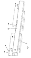
- a simplified perspective exploded view of a first support means of a stand device of a flat screen assembly according to the invention;
- Figure 2,
- a simplified perspective view of a support element of the first support means;
- Figure 3,
- a simplified perspective exploded view of a second support means of the stand device;
- Figure 4,
- a simplified perspective exploded view of the first support means, a fixing means and a base means of the stand device;
- Figure 5,
- a simplified perspective view of a cylinder of the fixing means;
- Figure 6,
- a simplified perspective view of the first and second support means and the fixing means, which are assembled together, and of the base means of the stand device;
- Figure 7,
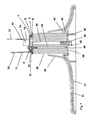
- a simplified cross section of the stand device with the first support means, the fixing means and the base means;
- Figure 8,
- a simplified cross section of the flat screen assembly with the stand device;
- Figure 9,
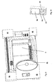
- a simplified rear view of a packing device of the flat screen assembly;
- Figure 10,
- a simplified perspective view of a packing device of an assembly of the fist support means and the fixing means;
- Figure 11,
- a simplified side view of the packing device of the flat screen assembly where the bottom plate is arranged parallel to the flat screen area; and
- Figure 12,
- a simplified side view of a packing device of an assembled flat screen assembly for comparison.
- A flat screen assembly of an embodiment of the invention comprises a flat screen panel P, which is generated e.g. by a LCD panel, and a stand device. As shown in figures, the flat screen panel P has a panel body, which basically has the shape of a cuboid. The flat screen panel P is provided with a housing with at least a
rear cover 1 and afront cover 2. The stand device comprises a base means, a fixing means, a first support means and a second support means. - The first support means which is shown in
figure 1 has a support element with arotating partition 3 and asupport partition 4, anouter washer 5, aninner washer 6, acover 7 and at least onefirst screw 8, in this embodiment threefirst screws 8. - The support element in another perspective is shown in
figure 2 . Therotating partition 3 of the support element is generated as a base plate with a circularfirst opening 9. - The
support partition 4 is generated as at least one plate, which is arranged perpendicularly to therotating partition 3. In this embodiment, thesupport partition 4 is generated as twoplates rotating partition 3. The cross section of the support element has the shape essentially of a U, where the base of the U is formed by therotating partition 3 and the sides of the U are formed by theplates support partition 4. In particular, theplate 10 is somewhat shifted toward the middle of thefirst opening 9, in order to fit with the second support means, the flat screen panel P and the housing of this exemplary embodiment. - The
plate 10 has a greater height than theplate 11. Theplate 10 is provided with anouter recess 12 in the middle of its outer edge and with twoholes 13 beside theouter recess 12 and with aninner recess 14 in the middle of its inner edge. Theplate 10 is adjoined to the base plate of therotating partition 3 at the sides of therecess 14. Theouter recess 12 has the shape of a rectangle and theinner recess 14 has the shape of a segment of a circle. The straight edge of the segment is placed adjacent to therotating partition 3 while its borrow edge is directed to theouter recess 12 of theplate 10. The shape of therecess 14 corresponds to the outer shape of the part of therotating partition 3, which protrudes theplate 10. In the assembled position, theouter washer 5 and thecover 7, which are arranged onto therotating partition 3, extend through therecess 14 and protrude theplate 10. Theplate 11 is provided with two holes withnuts 15 on the outer face of theplate 11. The holes with the nuts 15 are aligned with theholes 13. - The
support partition 4 has twolugs 16, which are arranged vis-à-vis at opposite sides from edges of the base plate of therotating partition 3 between theplates lugs 16 extend perpendicular to the base plate and to theplates 10 in the direction of theplates - The
lugs 16 are used to install the first support means to the second support means. In particular, thelugs 16 are used as stoppers at thepanel elements 23 which vertically place and stop the first support means in relation to the second support means. - The base plate of the
rotating partition 3 has the shape of a ring where its inner diameter is formed by thefirst opening 9 and where its outer diameter is provided with outer projections with straight edges in the regions of theplate 11 and of thelugs 16. The edge of the base plate is round beneath and protruding thesecond recess 14 of theplate 10. - The base plate of the
rotating partition 3 has aninner projection 17, which extends from the inner diameter into thefirst opening 9. Theprojection 17 is arranged at the side of theplate 10 beneath theinner recess 14. - In an embodiment of the invention the support element is manufactured from one flat metal sheet, where the shape of the
rotating partition 13 with theprojection 17, theplate 10 with theouter recess 12, theplate 11 and the twolugs 16 is cut out. Therecess 14 of theplate 10 and the outer shape of the part of therotating partition 3 protruding theplate 10 is generated by a cut between therotating partition 3 and theplate 10. After cutting out the shape of the support element, theplates lugs 16 are bended in a way that they extend in one direction perpendicularly to therotating partition 3. - The outer and
inner washers circular opening 18 and a thirdcircular opening 19. The outer diameter of theinner washer 6 is greater than the diameter of theouter washer 5. The inner diameter of theinner washer 6 is the same as the inner diameter of theouter washer 5. - The
cover 7 is generated as a cover plate, which is provided with threebosses 20 for thefirst screws 8 and acircular collar 21, which extend outwards from an inner face side of the cover plate. Thebosses 20 are equidistantly arranged at an inner diameter inside thecollar 21. The height of thebosses 20 is slightly greater than the height of thecollar 21. - The
collar 21 has anintermittence 22 within a sector of the collar circle. - The second support means, which is shown in
figures 3 and8 has asupport bar 23, two fixingelements 24 and twopanel elements 25. Thesupport bar 23 is generated as a profile with a rectangular cross cut. The fixingelements 24 are plates, which are connected to an edge of thesupport bar 23 with a certain distance to another and which, in an assembled position, are directed to the flat screen panel P. Each fixingelement 24 is provided with twoholes 26 for two panel screws 27 for fixing the second support means to the flat screen panel P. - The
panel elements 25 are plates, which are bended in an angle of 90°. In an assembled position, a first part of eachpanel element 25 extends from an opposite edge of thesupport bar 23 parallel to the flat screen area. A second part of eachpanel element 25 extends perpendicular to the flat screen area and the flat screen panel P. - The
support bar 23 is provided with twosecond screws 28 and holes 29 for thesecond screws 28 in its centre. The diameter of theholes 29 is slightly greater than the diameter of thescrews 28 in order to let it crossing thesupport bar 23 easily when fixing the first support means. - The fixing means comprises a
cylinder 30 with twoface sides first threads 33 extending from thefirst face side 31 into its interior for thefirst screws 8 of the first support means and with at least one, namely one,second thread 34 extending from the centre of thesecond face side 32 into its interior for athird screw 35. Thethreads first face side 31 to thesecond face side 32. - The fixing means comprises a first over
cover 36 for aesthetical reasons, which has the shape of a hollow cylinder and envelops thecylinder 30 in its lower part. - The base means comprises a
bottom plate 37, which has the shape of an ellipse and which has an elevation with acircular cavity 38 with an outer groove at one of the two centres of the ellipse. The diameter of thecavity 38 corresponds to the outer diameter of thecylinder 30 of the fixing means. Thebottom plate 37 has ahole 39 in the centre of thecavity 38 and apin 40. In an assembled position, thepin 40 extends in a corresponding hole of one of thefirst threads 33 of thecylinder 30 in order to avoid any rotation between thecylinder 30 and thebottom plate 37. - The base means comprises a second over
cover 41, also for aesthetical reasons. The shape of the second overcover 41 corresponds to the shape of thebottom plate 37, but instead of thecavity 38 it comprises a central hole with aflange 42 and with at least one arrestinglug 43, namely four arrestinglugs 43. Theflange 42 comprises two arrestingholes 44, which are provided for at least one arrestingpin 45 protruding from the first overcover 36 downwards. - In an assembled position, the fixing means is fixed to the base means, the first support means, namely the
rotating partition 3, is pivot-mounted between theouter washer 5 and theinner washer 6 to the fixing means and the second support means is fixed to the first support means and to the flat screen panel P. Theouter washer 5 and theinner washer 6 are fixed to the fixing means. - The fixing means is connected to the base means and to the first support means at the opposite face sides 31, 32 of the
cylinder 30, where the first support means with all its pieces is arranged on thefirst face side 31 of thecylinder 30. - The
cover 7 of the first support means is arranged on theouter washer 5 and fixed to the fixing means. In particular, thebosses 20 extend through theopenings outer washer 5, therotating partition 3 and theinner washer 6 up to thefirst face side 31 of thecylinder 30. The threefirst screws 8 extend from the top of thecover 7 through thebosses 20 and are fixed in thefirst threads 33 of thecylinder 30. - The
collar 21 of thecover 7 extends through theopenings outer washer 5 and therotating partition 3, while its outer face is generated as a slide face for therotating partition 3. - The
projection 17 of therotating partition 3 of the support element is arranged in the sector of theintermittence 22 of thecollar 21 of thecover 7. The sector of theintermittence 22 determines the movement of the flat screen panel P. - The second support means are fixed at the
support partition 4 of the support element of the first support means. Theholes 29 of thesupport bar 23 are aligned correspondingly to theholes 13 and the holes with thenuts 15 of the support element or the first support means, due to thelugs 16 of the support element. Thesupport bar 23 is fixed between the twoplates support bar 23 is fixed by the panel screws 27 to the flat screen panel P at its fixingelements 24, while the flat screen panel P is arranged on thepanel element 25. - The arresting lugs 43 of the second over
cover 41 are located in the outer groove of thecavity 38 of thebottom plate 37 beneath thecylinder 30. Thecylinder 30 is arranged in thecavity 38 of thebottom plate 37, while it is surrounded by the first overcover 36 at its lower part. - The support element with both the
rotating partition 3 and thesupport partition 4, which is manufactured from one metal sheet, has a thickness of 1,5 to 3 mm. - The
support bar 23, the fixingelements 24 and thepanel elements 25 of the second support means are manufactured from a metal, e.g. from aluminium. In particular, thesupport bar 23, the fixing 24 and thepanel elements 25 are generated as an extruded aluminium profile which is machined by milling and drilling. - The
cover 7 and thebottom plate 37 are manufactured form an aluminium die cast. Thewashers cylinder 30 is manufactured from extruded aluminium. The first and second overcover - The
rear cover 1 and thefront cover 2 are manufactured from a Polystyrene High Impact. - The screen size of this embodiment ranges e.g. from 11" to 60".
- A packing device for the flat screen assembly is shown in
figures 10 to 11 . It comprises threeedge parts stand part 49 with an edge part at the four edges of the housing. Thestand part 49 houses the base means and an assembly of the first support means and the fixing means. Thebottom plate 37 of the base means are arranged parallel to the area of the flat screen panel P. The assembly of fixing means and first support means is preassembled and arranged with thestand part 49 beside the base means. - This packing device with a flat screen assembly according to the invention which allows the base means to be arranged parallel to the flat screen panel P only needs a small space in comparison to a packing device for a flat screen assembly with fixed base means shown in
figure 12 . - The stand device according to the invention only needs a small number of elements of the first support means. The space for the stand device is reduced. As a result, the stand device reduces the dimension of the means providing the rotation function. New design solutions are possible. The volume of packing of the flat screen assembly is reduced. Efficiency and strength of the stand function are improved.
- The support means according to the invention also makes it possible to preassemble the first support means and the fixing means. The consumer only has to fix the assembly to the base means and then to the second support means. In order to fix the assembly with the base means to the second support means the customer has to move the assembly along the
support bar 23, align progressively theholes 13 andnuts 15 on theholes 29 and to fix thescrews 28. - As an alternative, the flat screen assembly has a flat screen panel P corresponding to the plasma technology.
Claims (10)
- A flat screen assembly comprising a flat screen panel (P) and a stand device, where the stand device comprises a base means, a fixing means, a first support means and a second support means,
where the first support means comprises a support element, an outer washer (5) and an inner washer (6),
where, in an assembled position,
the fixing means is fixed to the base means, the first support means is pivot-mounted to the fixing means, and the second support means is fixed to the first support means and to the flat screen panel (P), and
a rotating partition (3) of the support element is pivot-mounted between the outer and inner washers (5, 6), which are fixed to the fixing means. - A flat screen assembly according to claim 1, characterized in that, in the assembled position, the first support means is arranged on a face side of the fixing means.
- A flat screen assembly according to claim 1 or 2, characterized in that the first support means comprises a cover (7) where, in the assembled position, the cover (7) is arranged on the outer washer (5), where the cover (7) and the inner and outer washers (5, 6) are commonly fixed to the fixing means by at least one first screw (8).
- A flat screen assembly according to claim 3, characterized in that the cover is provided with a cylindrical collar (21) which, in the assembled position, protrudes through a corresponding second opening (18) of the outer washer (5) and a corresponding first opening (9) of the rotating partition (3) of the support element while an outer face of the collar (21) is generated as a slide face for the rotating partition (3).
- A flat screen assembly according to claim 4, characterized in that the collar (21) is provided with an intermittence (22) within a sector of the collar circle and the rotating partition (3) comprises a projection (17) extending into the second opening (18) where, in the assembled position, the projection (17) is arranged in the sector of the intermittence (22).
- A flat screen assembly according to one of the claims 1 to 5, characterized in that the support element comprises a support partition (4) at which, in the assembled position, the second support means are fixed.
- A flat screen assembly according to one of the claims 1 to 6, characterized in that the second support means comprises a support bar (23) which, in the assembled position, is fixed to the flat screen panel (P).
- A flat screen assembly according to claim 7, characterized in that the support partition (4) comprises two parallel plates (10, 11) where, in the assembled position, the support bar (23) is fixed between the two plates (10, 11).
- A flat screen assembly according to one of the claims 1 to 8, characterized in that the fixing means comprises a cylinder (30) which, in the assembled position, is connected to the base means and to the first support means at its opposite face sides (31, 32).
- A flat screen assembly according to one of the claims 1 to 9, characterized in that the base means comprises a plate, which is provided with a cylindrical groove (38) for the cylinder (30) of the fixing means.
Applications Claiming Priority (1)
| Application Number | Priority Date | Filing Date | Title |
|---|---|---|---|
| CNU2008201327398U CN201255966Y (en) | 2008-08-12 | 2008-08-12 | Planar display screen device |
Publications (2)
| Publication Number | Publication Date |
|---|---|
| EP2154415A2 true EP2154415A2 (en) | 2010-02-17 |
| EP2154415A3 EP2154415A3 (en) | 2011-11-02 |
Family
ID=40739292
Family Applications (1)
| Application Number | Title | Priority Date | Filing Date |
|---|---|---|---|
| EP09000338A Withdrawn EP2154415A3 (en) | 2008-08-12 | 2009-01-13 | Flat screen assembly with a stand device |
Country Status (2)
| Country | Link |
|---|---|
| EP (1) | EP2154415A3 (en) |
| CN (1) | CN201255966Y (en) |
Cited By (1)
| Publication number | Priority date | Publication date | Assignee | Title |
|---|---|---|---|---|
| EP3211885A4 (en) * | 2014-10-21 | 2018-07-04 | Boe Technology Group Co. Ltd. | Television pedestal and television applying same |
Families Citing this family (1)
| Publication number | Priority date | Publication date | Assignee | Title |
|---|---|---|---|---|
| CN102705653A (en) * | 2012-06-25 | 2012-10-03 | 苏州胜利精密制造科技股份有限公司 | X-shaped liquid crystal television base |
Citations (2)
| Publication number | Priority date | Publication date | Assignee | Title |
|---|---|---|---|---|
| JP2006227390A (en) | 2005-02-18 | 2006-08-31 | Munekata Co Ltd | Turning unit for monitor stand |
| CN2927554Y (en) | 2006-06-30 | 2007-07-25 | 新科电子集团有限公司 | Base device of liquid-crystal TV-set |
Family Cites Families (2)
| Publication number | Priority date | Publication date | Assignee | Title |
|---|---|---|---|---|
| JP2007271061A (en) * | 2006-03-31 | 2007-10-18 | Casio Hitachi Mobile Communications Co Ltd | Hinge unit |
| CN101427299B (en) * | 2006-06-28 | 2012-05-30 | 爱尔康公司 | Control display positioning system |
-
2008
- 2008-08-12 CN CNU2008201327398U patent/CN201255966Y/en not_active Expired - Lifetime
-
2009
- 2009-01-13 EP EP09000338A patent/EP2154415A3/en not_active Withdrawn
Patent Citations (2)
| Publication number | Priority date | Publication date | Assignee | Title |
|---|---|---|---|---|
| JP2006227390A (en) | 2005-02-18 | 2006-08-31 | Munekata Co Ltd | Turning unit for monitor stand |
| CN2927554Y (en) | 2006-06-30 | 2007-07-25 | 新科电子集团有限公司 | Base device of liquid-crystal TV-set |
Cited By (1)
| Publication number | Priority date | Publication date | Assignee | Title |
|---|---|---|---|---|
| EP3211885A4 (en) * | 2014-10-21 | 2018-07-04 | Boe Technology Group Co. Ltd. | Television pedestal and television applying same |
Also Published As
| Publication number | Publication date |
|---|---|
| CN201255966Y (en) | 2009-06-10 |
| EP2154415A3 (en) | 2011-11-02 |
Similar Documents
| Publication | Publication Date | Title |
|---|---|---|
| CN203573585U (en) | Small-spacing light-emitting diode (LED) display screen | |
| WO2012096328A1 (en) | Tablet cassette | |
| JP2014008897A (en) | Door mirror | |
| US8558111B1 (en) | Round box to single gang cover adapter | |
| JP2021512749A (en) | Fixed placement for WC flap elements | |
| CA3078076A1 (en) | Push-pull passage lock mounting device adapted to doors in various sizes | |
| US20140021217A1 (en) | Vending machine with product receiving structure | |
| EP2159892A2 (en) | Adjustable mounting bracket and a distribution box having the same | |
| US20120304457A1 (en) | Mounting apparatus for circuit board | |
| US8408662B2 (en) | Electronic device enclosure | |
| US9101073B2 (en) | Server cabinet | |
| US8749973B2 (en) | Electronic device enclosure | |
| US8787027B2 (en) | Mounting apparatus for circuit board | |
| CN201255966Y (en) | Planar display screen device | |
| CN103341762B (en) | A kind of rotating concealed control panel device | |
| JP5443139B2 (en) | Air filter mounting mechanism | |
| JP4805098B2 (en) | Pivot hinge | |
| US20120170219A1 (en) | Electronic device | |
| CN212361415U (en) | Base mounting structure and camera device | |
| JP5964104B2 (en) | Electronic equipment housing | |
| CN223065696U (en) | Laptop | |
| US20140117185A1 (en) | Sensor mounting apparatus | |
| CN208744083U (en) | Auto License plate board fixture nut press-mounting detecting device | |
| EP2301765B1 (en) | Castor | |
| CN222320437U (en) | Side fan fixing structure of battery compartment of charging cabinet |
Legal Events
| Date | Code | Title | Description |
|---|---|---|---|
| PUAI | Public reference made under article 153(3) epc to a published international application that has entered the european phase |
Free format text: ORIGINAL CODE: 0009012 |
|
| AK | Designated contracting states |
Kind code of ref document: A2 Designated state(s): AT BE BG CH CY CZ DE DK EE ES FI FR GB GR HR HU IE IS IT LI LT LU LV MC MK MT NL NO PL PT RO SE SI SK TR |
|
| AX | Request for extension of the european patent |
Extension state: AL BA RS |
|
| PUAL | Search report despatched |
Free format text: ORIGINAL CODE: 0009013 |
|
| AK | Designated contracting states |
Kind code of ref document: A3 Designated state(s): AT BE BG CH CY CZ DE DK EE ES FI FR GB GR HR HU IE IS IT LI LT LU LV MC MK MT NL NO PL PT RO SE SI SK TR |
|
| AX | Request for extension of the european patent |
Extension state: AL BA RS |
|
| RIC1 | Information provided on ipc code assigned before grant |
Ipc: F16M 11/08 20060101AFI20110923BHEP |
|
| AKY | No designation fees paid | ||
| REG | Reference to a national code |
Ref country code: DE Ref legal event code: R108 |
|
| REG | Reference to a national code |
Ref country code: DE Ref legal event code: R108 Effective date: 20120711 |
|
| STAA | Information on the status of an ep patent application or granted ep patent |
Free format text: STATUS: THE APPLICATION IS DEEMED TO BE WITHDRAWN |
|
| 18D | Application deemed to be withdrawn |
Effective date: 20120503 |