EP2154346A1 - Sealing gasket for exhaust pipes - Google Patents
Sealing gasket for exhaust pipes Download PDFInfo
- Publication number
- EP2154346A1 EP2154346A1 EP09009481A EP09009481A EP2154346A1 EP 2154346 A1 EP2154346 A1 EP 2154346A1 EP 09009481 A EP09009481 A EP 09009481A EP 09009481 A EP09009481 A EP 09009481A EP 2154346 A1 EP2154346 A1 EP 2154346A1
- Authority
- EP
- European Patent Office
- Prior art keywords
- gasket
- rib
- zone
- exhaust pipes
- flanges
- Prior art date
- Legal status (The legal status is an assumption and is not a legal conclusion. Google has not performed a legal analysis and makes no representation as to the accuracy of the status listed.)
- Withdrawn
Links
Images

Classifications
-
- F—MECHANICAL ENGINEERING; LIGHTING; HEATING; WEAPONS; BLASTING
- F01—MACHINES OR ENGINES IN GENERAL; ENGINE PLANTS IN GENERAL; STEAM ENGINES
- F01N—GAS-FLOW SILENCERS OR EXHAUST APPARATUS FOR MACHINES OR ENGINES IN GENERAL; GAS-FLOW SILENCERS OR EXHAUST APPARATUS FOR INTERNAL-COMBUSTION ENGINES
- F01N13/00—Exhaust or silencing apparatus characterised by constructional features
- F01N13/18—Construction facilitating manufacture, assembly, or disassembly
- F01N13/1805—Fixing exhaust manifolds, exhaust pipes or pipe sections to each other, to engine or to vehicle body
- F01N13/1827—Sealings specially adapted for exhaust systems
-
- F—MECHANICAL ENGINEERING; LIGHTING; HEATING; WEAPONS; BLASTING
- F16—ENGINEERING ELEMENTS AND UNITS; GENERAL MEASURES FOR PRODUCING AND MAINTAINING EFFECTIVE FUNCTIONING OF MACHINES OR INSTALLATIONS; THERMAL INSULATION IN GENERAL
- F16J—PISTONS; CYLINDERS; SEALINGS
- F16J15/00—Sealings
- F16J15/02—Sealings between relatively-stationary surfaces
- F16J15/06—Sealings between relatively-stationary surfaces with solid packing compressed between sealing surfaces
- F16J15/08—Sealings between relatively-stationary surfaces with solid packing compressed between sealing surfaces with exclusively metal packing
- F16J15/0818—Flat gaskets
-
- F—MECHANICAL ENGINEERING; LIGHTING; HEATING; WEAPONS; BLASTING
- F16—ENGINEERING ELEMENTS AND UNITS; GENERAL MEASURES FOR PRODUCING AND MAINTAINING EFFECTIVE FUNCTIONING OF MACHINES OR INSTALLATIONS; THERMAL INSULATION IN GENERAL
- F16L—PIPES; JOINTS OR FITTINGS FOR PIPES; SUPPORTS FOR PIPES, CABLES OR PROTECTIVE TUBING; MEANS FOR THERMAL INSULATION IN GENERAL
- F16L23/00—Flanged joints
- F16L23/16—Flanged joints characterised by the sealing means
- F16L23/18—Flanged joints characterised by the sealing means the sealing means being rings
-
- F—MECHANICAL ENGINEERING; LIGHTING; HEATING; WEAPONS; BLASTING
- F16—ENGINEERING ELEMENTS AND UNITS; GENERAL MEASURES FOR PRODUCING AND MAINTAINING EFFECTIVE FUNCTIONING OF MACHINES OR INSTALLATIONS; THERMAL INSULATION IN GENERAL
- F16J—PISTONS; CYLINDERS; SEALINGS
- F16J15/00—Sealings
- F16J15/02—Sealings between relatively-stationary surfaces
- F16J15/06—Sealings between relatively-stationary surfaces with solid packing compressed between sealing surfaces
- F16J15/08—Sealings between relatively-stationary surfaces with solid packing compressed between sealing surfaces with exclusively metal packing
- F16J15/0818—Flat gaskets
- F16J2015/0837—Flat gaskets with an edge portion folded over a second plate or shim
-
- F—MECHANICAL ENGINEERING; LIGHTING; HEATING; WEAPONS; BLASTING
- F16—ENGINEERING ELEMENTS AND UNITS; GENERAL MEASURES FOR PRODUCING AND MAINTAINING EFFECTIVE FUNCTIONING OF MACHINES OR INSTALLATIONS; THERMAL INSULATION IN GENERAL
- F16J—PISTONS; CYLINDERS; SEALINGS
- F16J15/00—Sealings
- F16J15/02—Sealings between relatively-stationary surfaces
- F16J15/06—Sealings between relatively-stationary surfaces with solid packing compressed between sealing surfaces
- F16J15/08—Sealings between relatively-stationary surfaces with solid packing compressed between sealing surfaces with exclusively metal packing
- F16J15/0818—Flat gaskets
- F16J2015/0862—Flat gaskets with a bore ring
Definitions
- the present invention generally relates to a sealing gasket for exhaust pipes.
- the present invention relates to a sealing gasket to be applied to pairs of flanges connected to the ends of exhaust pipes in order to ensure tightness between the flanges and to prevent leaks of exhaust gases.
- Sealing gaskets to be inserted between flanges located at the ends of exhaust pipes in order to prevent leaks of exhaust gases in correspondence of connection regions between the exhaust pipes are well known.
- sealing gaskets are known that include an insert of refractory material in correspondence of the connection region in order to improve the tightness of the gasket
- a sealing gasket known from patent publication EP_1267049_A1 includes a ring of refractory material encapsulated in a first metal sheet folded with overlapping edges so as to have a toroidal shape (toroidal element), and a second metal sheet with substantially oval shape having a central hole whose diameter is slightly smaller than the outside diameter of the ring and whose inner rim is sandwiched between the overlapping edges of the first metal sheet.
- the second sheet of the prior art document is arranged to form two plane surfaces extending on a middle plane of the toroidal element.
- the prior art gasket in use, operates in correspondence of a region where the flanges face each other and have facing folding radii so as to form a cavity housing the toroidal element of the gasket.
- a first problem of such a prior art is that the sealing action of the gasket is provided by the toroidal element only, whereas the remaining plane portion, with oval shape, only assists in positioning the gasket and signalling the presence thereof.
- a further problem of the prior art gasket is that anyway it demands assembling two metal sheets.
- gaskets including an insert of refractory material at the flange connection region in order to improve the sealing action of the gasket are also known.
- a sealing gasket known from patent publication EP_1386099_A1 demands providing two metal sheets to be arranged in facing relationship and to be suitably folded so as to form facing ribs capable of holding the insert of refractory material so as to form a toroidal sealing element.
- such a gasket has the problem that the sealing action of the gasket is provided by the toroidal element in cooperation only with the outer plane ends of the opposite ribs, which work on the plane surfaces of the flanges.
- Second, such a gasket has the problem that it demands, for its manufacture, the provision of two metal sheets that are to be inserted in facing relationship between the flanges and are configured so as to hold the insert of refractory material.
- the object is achieve by the sealing gasket for exhaust pipes as claimed.
- the present invention also concerns a method of operation of a gasket with an insert of refractory material.
- the sealing gasket for exhaust pipes to be inserted between facing surfaces of end flanges comprises a metallic body having a refractory element in a first zone and at least one rib in a second zone, which rib has at least one ridge (top) arranged to exert pressure on at least one of the facing surfaces of the flanges and to operate elastically.
- the gasket includes S-shaped ribs, or single and/or multiple ribs.
- the gasket has an opening for the passage of exhaust gases, which is larger than or equal in size to a corresponding opening formed in the end or opposite flange,
- a sealing gasket 10 for exhaust pipes comprises a body 12, for instance made from a sheet of metallic material such as stainless steel AISI 304, and an insert or refractory element 14 having a predetermined thickness h', capable of resisting high temperatures (800°C - 900°C) and made for instance of mineral fibre materials, such as commercially available materials intended for insulation.
- Body 12 has for instance a triangular outline, the corners of which are preferably equipped with holes 23 arranged to enable clamping gasket 10 between end or opposite flanges 15a and 15b ( Fig. 1 , Fig, 3 ) fastened, in known manner, by mean of fastening members 19, to the ends of respective exhaust pipes 18a and 18b to be joined, and shaped so as to form an opening with predetermined shape for the passage of exhaust gases.
- body 12 may have an ovoid outline, or an outline with more than three sides, without thereby departing from the scope of the description and claims.
- Body 12 further includes an opening 21, preferably barycentrically located relative to the body, having an edge 22 with such a size as to enable passage of exhaust gases for instance from an engine.
- Opening (gas passage hole) 21 preferably has circular shape and such a shape is referred to in the Figures and the description, even though other shapes, for instance ovoid shapes, quadrangular shapes, etc., are possible without thereby departing from the scope of the description and claims.
- Body 12 is preferably made from a single foil of metal sheet and it includes an active region 31, formed near edge 22 of opening (gas passage hole) 21 and arranged to cooperate with flanges 15a and 15b in order to provide a seal in respect of exhaust gases, and a fastening region 33, formed in correspondence of holes 23 (fastening holes) and arranged to be used for fastening gasket 10 to flanges 15a and 15b.
- Fastening region 33 preferably has a plane surface.
- Active region 31 includes, from edge 22 of gas passage hole 21 towards fastening region 33:
- ribs 45a are S-shaped and have constant height h and projecting ridges 46a. Such ridges may have a curved or a sharp shape.
- ribs 45b are single or multiple ribs and have constant height h and projecting ridges 46a. Such ridges may have a curved or a sharp shape.
- Both embodiments enable, especially in case of sharp ridges, concentrating the contact in a very small area of the flanges, thereby obtaining a very high specific pressure.
- Ribs 45a in accordance with the first embodiment preferably have a greater height h than ribs 45b in accordance with the second embodiment.
- height h of ribs 45a or 45b is determined depending on thickness h' and the pliability characteristics of the fibrous element. For instance, for a same fibrous element, height h of the ribs made in accordance with the first embodiment ranges from 1.0 to 1.5 mm, and height h of the ribs made in accordance with the second embodiment ranges from 0.8 to 1.2 mm: different elastic characteristics of the ribs can thus be achieved, by using different thicknesses and/or materials for the metal sheet foil.
- a layer or sheet in particular in case of flanges having high rigidity, it is provided to arrange a layer or sheet, preferably made of metal (for instance stainless steel), in an area corresponding to the fastening region 33.
- the layer or sheet (metal sheet) is preferably shaped so as to extend to all the fastening holes 23,
- fastening members 19, for instance bolts are tightened, it is possible to ensure a constant mechanical response of the gasket 10 so as to avoid that bolts tightening affects or is affected by the active region 31,
- gasket 10 ( Fig. 1, Fig. 2a , Fig. 2b, Fig. 3 ) described above is as follows.
- gasket 10 is positioned between flanges 15a and 15b, welded or fastened to exhaust pipes 18a and 18b, respectively, to be joined.
- the flanges preferably have facing plane surfaces and the pipes are fastened to the flanges so that they do no project out from the respective plane surfaces of the flanges.
- fastening members 19 such as bolts of known type or stud bolts, are inserted into fastening holes 23, and the fastening members are locked, whereby flanges 15a and 15b are frontally brought close to each other.
- active region 31 of gasket 10 is compressed so that the first zone (folding zone) 41 first undergoes a plastic deformation and then operates elastically.
- folding zone 41 stops the frontal approach of the flanges, so that also ribs 45a or 45b are loaded at their ridges 46a or 46b so as to operate elastically with characteristics depending on the embodiment selected.
- the elastic action of active region 31 is such that it ensures exhaust gas tightness both in case of small displacements of the flanges, due for instance to thermal variations, and in case of mechanical vibrations, due for instance to vibrations of the engine.
- the gasket described herein by working in correspondence of the facing surfaces of the flanges, does not require a particularly precise centring relative to the flanges.
- the shape of the ribs in the first embodiment enables compensating greater shape irregularities in the flanges than those that can be compensated with the second embodiment.
- the first embodiment allows sags of greater amplitude than allowed by the second embodiment.
- rib shapes are possible, for instance shapes in which the ribs are a combination of both embodiments described or in which rib height h changes depending on the distance from edge 22 of opening 21, without thereby departing from the scope of the description and claims.
- Part of the ribs can also be formed in areas that are not adjacent to folding zone 41, for instance at a distance of 2 - 3 mm from such a zone 41, in order to better compensate surface defects of the flange surfaces.
- the construction of the gasket according to the present invention preferably comprises a sequence of cold mechanical operations, including:
Landscapes
- Engineering & Computer Science (AREA)
- General Engineering & Computer Science (AREA)
- Mechanical Engineering (AREA)
- Chemical & Material Sciences (AREA)
- Combustion & Propulsion (AREA)
- Gasket Seals (AREA)
- Joints With Sleeves (AREA)
- Sealing Material Composition (AREA)
Abstract
The present invention relates to a sealing gasket for exhaust pipes, to be inserted between facing surfaces of opposite flanges (15a, 15b) fastened to the ends of the exhaust pipes (18a, 18b) and comprising a refractory element (14) and a metallic body (12) shaped so as to contain the refractory element (14) and to provide a zone with an opening (21) for the passage of exhaust gases. The gasket has at least one rib having at least one ridge and arranged to exert pressure, with said at least one ridge, on at least one of the facing surfaces of the opposite flanges and to operate elastically. The invention also concerns the method of operation of the gasket.
Description
- The present invention generally relates to a sealing gasket for exhaust pipes.
- More particularly, the present invention relates to a sealing gasket to be applied to pairs of flanges connected to the ends of exhaust pipes in order to ensure tightness between the flanges and to prevent leaks of exhaust gases.
- Sealing gaskets to be inserted between flanges located at the ends of exhaust pipes in order to prevent leaks of exhaust gases in correspondence of connection regions between the exhaust pipes are well known.
- In particular, sealing gaskets are known that include an insert of refractory material in correspondence of the connection region in order to improve the tightness of the gasket
- For instance, a sealing gasket known from patent publication
EP_1267049_A1 includes a ring of refractory material encapsulated in a first metal sheet folded with overlapping edges so as to have a toroidal shape (toroidal element), and a second metal sheet with substantially oval shape having a central hole whose diameter is slightly smaller than the outside diameter of the ring and whose inner rim is sandwiched between the overlapping edges of the first metal sheet. - The second sheet of the prior art document is arranged to form two plane surfaces extending on a middle plane of the toroidal element.
- The prior art gasket, in use, operates in correspondence of a region where the flanges face each other and have facing folding radii so as to form a cavity housing the toroidal element of the gasket.
- A first problem of such a prior art is that the sealing action of the gasket is provided by the toroidal element only, whereas the remaining plane portion, with oval shape, only assists in positioning the gasket and signalling the presence thereof.
- Another problem of the prior art gasket is that the toroidal element, which in use works within a cavity, demands a particularly precise mounting; actually, otherwise, the risk exists that the toroidal element does not provide a seal because of a different pressure distribution due to a different compression exerted by the flanges along the circumference of the toroidal element.
- A further problem of the prior art gasket is that anyway it demands assembling two metal sheets.
- Other gaskets including an insert of refractory material at the flange connection region in order to improve the sealing action of the gasket are also known.
- For instance, a sealing gasket known from patent publication EP_1386099_A1 demands providing two metal sheets to be arranged in facing relationship and to be suitably folded so as to form facing ribs capable of holding the insert of refractory material so as to form a toroidal sealing element.
- First of all, such a gasket has the problem that the sealing action of the gasket is provided by the toroidal element in cooperation only with the outer plane ends of the opposite ribs, which work on the plane surfaces of the flanges. Second, such a gasket has the problem that it demands, for its manufacture, the provision of two metal sheets that are to be inserted in facing relationship between the flanges and are configured so as to hold the insert of refractory material.
- By summarising, the Applicant has realised that the prior art gaskets including inserts of refractory material cannot effectively solve the problem of ensuring an optimum tightness, especially in case the mounting is scarcely precise.
- The Applicant also has realised that the prior art gaskets demand particularly complex manufacturing processes, such as for instance the provision of two sheets to be joined.
- It is an object of the present invention to provide a gasket with a refractory insert, which overcomes the problems mentioned above of the prior art.
- The object is achieve by the sealing gasket for exhaust pipes as claimed.
- The present invention also concerns a method of operation of a gasket with an insert of refractory material.
- The claims are an integral part of the technical teaching provided herein in respect of the invention.
- In accordance with a feature of a preferred embodiment, the sealing gasket for exhaust pipes to be inserted between facing surfaces of end flanges comprises a metallic body having a refractory element in a first zone and at least one rib in a second zone, which rib has at least one ridge (top) arranged to exert pressure on at least one of the facing surfaces of the flanges and to operate elastically.
- In accordance with another feature of the present invention, the gasket includes S-shaped ribs, or single and/or multiple ribs.
- In accordance with a further feature of the present invention, the gasket has an opening for the passage of exhaust gases, which is larger than or equal in size to a corresponding opening formed in the end or opposite flange,
- The above and other features and advantages of the present invention will become apparent from the following description of preferred embodiments, made by way of non limiting example with reference to the accompanying drawings, in which elements denoted by a same or similar numerical reference denote elements having the same or similar functionality, and in which:
-
Fig. 1 is a front view of a gasket according to the invention; -
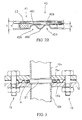
Fig. 2a is a detail of a first embodiment of the gasket depicted inFig. 1 ; -
Fig. 2b is a detail of a second embodiment of the gasket depicted inFig. 1 ; and -
Fig. 3 is an exemplary assembly of the gasket according to the invention. - Referring to
Fig. 1 , a sealinggasket 10 for exhaust pipes according to the present invention comprises abody 12, for instance made from a sheet of metallic material such as stainless steel AISI 304, and an insert orrefractory element 14 having a predetermined thickness h', capable of resisting high temperatures (800°C - 900°C) and made for instance of mineral fibre materials, such as commercially available materials intended for insulation. -
Body 12 has for instance a triangular outline, the corners of which are preferably equipped withholes 23 arranged to enable clampinggasket 10 between end oropposite flanges Fig. 1 ,Fig, 3 ) fastened, in known manner, by mean of fasteningmembers 19, to the ends ofrespective exhaust pipes - Of course, in other embodiments,
body 12 may have an ovoid outline, or an outline with more than three sides, without thereby departing from the scope of the description and claims. -
Body 12 further includes anopening 21, preferably barycentrically located relative to the body, having anedge 22 with such a size as to enable passage of exhaust gases for instance from an engine. - Opening (gas passage hole) 21 preferably has circular shape and such a shape is referred to in the Figures and the description, even though other shapes, for instance ovoid shapes, quadrangular shapes, etc., are possible without thereby departing from the scope of the description and claims.
-
Body 12 is preferably made from a single foil of metal sheet and it includes anactive region 31, formed nearedge 22 of opening (gas passage hole) 21 and arranged to cooperate withflanges fastening region 33, formed in correspondence of holes 23 (fastening holes) and arranged to be used for fasteninggasket 10 toflanges - Fastening
region 33 preferably has a plane surface. -
Active region 31 includes, fromedge 22 ofgas passage hole 21 towards fastening region 33: - a first zone 41 (
Fig. 2a andFig. 2b ), obtained for instance by folding the sheet and configured so as to house refractory element (fibrous element) 14, Generally, the first zone (folding zone) 41 has an opening whose size is larger than or equal to the size of the gas passage opening formed in the end flanges and, in the manufacturing phase, it is formed with a predetermined thickness "z"; more preferably,folding zone 41 has an opening whose size is slightly larger (e.g. 0.5 mm) than the size of the opening formed inend flanges - a
second zone 43, preferably adjacent to thefirst zone 41 and comprising one ormore ribs - In accordance with a first embodiment, which is deemed to be preferable,
ribs 45a (one or more) are S-shaped and have constant height h and projectingridges 46a. Such ridges may have a curved or a sharp shape. - In accordance with a second embodiment,
ribs 45b (one or more) are single or multiple ribs and have constant height h and projectingridges 46a. Such ridges may have a curved or a sharp shape. - Both embodiments enable, especially in case of sharp ridges, concentrating the contact in a very small area of the flanges, thereby obtaining a very high specific pressure.
-
Ribs 45a in accordance with the first embodiment preferably have a greater height h thanribs 45b in accordance with the second embodiment. - More preferably, height h of
ribs - According to a further embodiment, in particular in case of flanges having high rigidity, it is provided to arrange a layer or sheet, preferably made of metal (for instance stainless steel), in an area corresponding to the
fastening region 33.
According to said further embodiment, the layer or sheet (metal sheet) is preferably shaped so as to extend to all thefastening holes 23,
In operation, thanks to such embodiment, when fasteningmembers 19, for instance bolts, are tightened, it is possible to ensure a constant mechanical response of thegasket 10 so as to avoid that bolts tightening affects or is affected by theactive region 31, - The operation of gasket 10 (
Fig. 1, Fig. 2a ,Fig. 2b, Fig. 3 ) described above is as follows. - In a first step,
gasket 10 is positioned betweenflanges exhaust pipes - In a second step, fastening
members 19, such as bolts of known type or stud bolts, are inserted into fasteningholes 23, and the fastening members are locked, wherebyflanges - During the step of gasket locking between the facing surfaces of the flanges,
active region 31 ofgasket 10 is compressed so that the first zone (folding zone) 41 first undergoes a plastic deformation and then operates elastically. - The plastic deformation of
folding zone 41 stops the frontal approach of the flanges, so that alsoribs ridges - At the end of the locking step, the elastic action of
active region 31 is such that it ensures exhaust gas tightness both in case of small displacements of the flanges, due for instance to thermal variations, and in case of mechanical vibrations, due for instance to vibrations of the engine. - Advantageously, the gasket described herein, by working in correspondence of the facing surfaces of the flanges, does not require a particularly precise centring relative to the flanges.
- Moreover, as the skilled in the art can readily appreciate, the shape of the ribs in the first embodiment enables compensating greater shape irregularities in the flanges than those that can be compensated with the second embodiment. The first embodiment allows sags of greater amplitude than allowed by the second embodiment.
- Of course, also other rib shapes are possible, for instance shapes in which the ribs are a combination of both embodiments described or in which rib height h changes depending on the distance from
edge 22 ofopening 21, without thereby departing from the scope of the description and claims. - Part of the ribs can also be formed in areas that are not adjacent to
folding zone 41, for instance at a distance of 2 - 3 mm from such azone 41, in order to better compensate surface defects of the flange surfaces. - The construction of the gasket according to the present invention preferably comprises a sequence of cold mechanical operations, including:
- shearing the metallic material so as to obtain the outer shape of
body 12, fastening holes 23 and agas passage hole 21 with a size enablingfolding edge 22 overfibrous element 14; of course, such a hole will have a size previously determined, for instance, according to the design specifications; - forming the ribs by pressing or drawing, by bending
edge 22 of opening 21 preferably at right angle or at an angle slightly smaller than 90° so as to form ahousing cavity 25; - positioning
fibrous element 14 intohousing cavity 25; of course,fibrous element 14 is preferably obtained in advance and in know manner by shearing, for instance from a sheet or a plate or a roll of fibrous material; - folding
edge 22 overfibrous element 14, for instance by means of a conical punch. - The gasket made in this manner is ready for use.
- Of course, obvious modifications and/or variations can be made to the above description, in respect of the size, shapes, materials and components, as well as in the details of the illustrated construction and the operating method, without departing from the scope of the invention as set forth in the following claims.
Claims (10)
- Sealing gasket for exhaust pipes to be inserted between facing surfaces of opposite flanges (15a, 15b) fastened to the ends of the exhaust pipes (18a, 18b), comprising- a refractory element (14);- a metallic body (12) shaped so as to contain said refractory element (14) and to provide a zone (41) with an opening (21) for the passage of exhaust gases;
characterised by- at least one rib (45a, 45b) having at least one top (46a, 46b) arranged to exercise pressure, with said at least one top, on at least one of the facing surfaces of the opposite flanges (15a, 15b) and to operate elastically. - Gasket according to claim 1, wherein said at least one rib (45a) is a "S" shaped rib.
- Gasket according to claim 2, wherein said at least one rib (45a) has a height (h) ranging between 1.0 and 1.5 mm.
- Gasket according to claim 1, wherein said at least one rib (45b) is a single rib or a multi rib.
- Gasket according to claim 4, wherein said at least one rib (45b) has a height (h) ranging between 0.8 and 1.2 mm.
- Gasket according to any one of claims 1 to 5, wherein- said opening (21) of said metallic body (12) is larger than or equal in size to a corresponding opening in said opposite flanges (15a, 15b).
- Gasket according to any one of claims 1 to 6, wherein- said zone (41) with an opening (21) for the passage of exhaust gases has a shape selected from the following shapes:- a circular shape;- an ovoidal shape;- a quadrangular shape.
- Gasket according to any one of claims 1 to 7 wherein said body has an outline selected from the following outlines- an ovoidal outline;- a triangular outline;- an outline with more than three sides.
- Working method of a sealing gasket for exhaust pipes to be inserted between facing surfaces of opposite flanges (15a, 15b) fastened to the ends of the exhaust pipes (18a, 18b), said gasket comprising in a first zone (41) a refractory element (14) and in a second zone (43) at least one rib (45a, 45b) having at least one top (46a, 46b), characterised by the step of- making said at least one gasket (10) operate elastically by exercising pressure with said at least one top (46a, 46b) on at least one of the facing surfaces of the opposite flanges (15a, 15b).
- Method according to claim 9, wherein said step of making the gasket operate elastically comprises- applying a plastic strain in said first zone (41);- making said first zone (41) and said second zone (43) operate elastically.
Applications Claiming Priority (1)
| Application Number | Priority Date | Filing Date | Title |
|---|---|---|---|
| IT000593A ITTO20080593A1 (en) | 2008-07-30 | 2008-07-30 | SEALING GASKET FOR DRAIN PIPES. |
Publications (1)
| Publication Number | Publication Date |
|---|---|
| EP2154346A1 true EP2154346A1 (en) | 2010-02-17 |
Family
ID=40751079
Family Applications (1)
| Application Number | Title | Priority Date | Filing Date |
|---|---|---|---|
| EP09009481A Withdrawn EP2154346A1 (en) | 2008-07-30 | 2009-07-22 | Sealing gasket for exhaust pipes |
Country Status (2)
| Country | Link |
|---|---|
| EP (1) | EP2154346A1 (en) |
| IT (1) | ITTO20080593A1 (en) |
Cited By (2)
| Publication number | Priority date | Publication date | Assignee | Title |
|---|---|---|---|---|
| CN103470767A (en) * | 2012-06-08 | 2013-12-25 | 中国核动力研究设计院 | Duplex compensation damping shunt axial sealing ring |
| WO2016114323A1 (en) * | 2015-01-14 | 2016-07-21 | Nok株式会社 | Gasket |
Citations (4)
| Publication number | Priority date | Publication date | Assignee | Title |
|---|---|---|---|---|
| EP0242868A1 (en) * | 1986-04-22 | 1987-10-28 | Nippon Reinz Co.,Ltd. | Joint means having flanges |
| EP0267049A2 (en) | 1986-11-06 | 1988-05-11 | Thomas Jefferson University | Method of determining endothelial cell coverage of a prosthetic surface |
| EP1386099A1 (en) | 2001-05-09 | 2004-02-04 | Meillor S.A. | Metallic joint with fibrous insert |
| FR2905439A1 (en) * | 2006-09-05 | 2008-03-07 | Freudenberg Meillor Soc Par Ac | Sealing joint for exhaust line, has metal plate including housing with variable volume and volume variation unit that stops reduction of volume to non-null minimum value and receives elastic insert that is against reduction of volume |
-
2008
- 2008-07-30 IT IT000593A patent/ITTO20080593A1/en unknown
-
2009
- 2009-07-22 EP EP09009481A patent/EP2154346A1/en not_active Withdrawn
Patent Citations (4)
| Publication number | Priority date | Publication date | Assignee | Title |
|---|---|---|---|---|
| EP0242868A1 (en) * | 1986-04-22 | 1987-10-28 | Nippon Reinz Co.,Ltd. | Joint means having flanges |
| EP0267049A2 (en) | 1986-11-06 | 1988-05-11 | Thomas Jefferson University | Method of determining endothelial cell coverage of a prosthetic surface |
| EP1386099A1 (en) | 2001-05-09 | 2004-02-04 | Meillor S.A. | Metallic joint with fibrous insert |
| FR2905439A1 (en) * | 2006-09-05 | 2008-03-07 | Freudenberg Meillor Soc Par Ac | Sealing joint for exhaust line, has metal plate including housing with variable volume and volume variation unit that stops reduction of volume to non-null minimum value and receives elastic insert that is against reduction of volume |
Cited By (4)
| Publication number | Priority date | Publication date | Assignee | Title |
|---|---|---|---|---|
| CN103470767A (en) * | 2012-06-08 | 2013-12-25 | 中国核动力研究设计院 | Duplex compensation damping shunt axial sealing ring |
| WO2016114323A1 (en) * | 2015-01-14 | 2016-07-21 | Nok株式会社 | Gasket |
| CN107110359A (en) * | 2015-01-14 | 2017-08-29 | Nok株式会社 | Pad |
| JPWO2016114323A1 (en) * | 2015-01-14 | 2017-10-19 | Nok株式会社 | gasket |
Also Published As
| Publication number | Publication date |
|---|---|
| ITTO20080593A1 (en) | 2010-01-31 |
Similar Documents
| Publication | Publication Date | Title |
|---|---|---|
| KR101560565B1 (en) | Comby two-sided overlain gasket for sealing of dismountable flanged joints | |
| JP3738121B2 (en) | Metal gasket | |
| EP3557107B1 (en) | Gasketed pipe clamp | |
| US8118551B2 (en) | Casing and fluid machine | |
| US20130106066A1 (en) | Layered seal for turbomachinery | |
| US20100295298A1 (en) | Device for pre-stressed sealed connection with flanges | |
| JPH05602Y2 (en) | ||
| EP3182048A1 (en) | Porthole gasket, assembly for a heat exchanger and heat exchanger comprising such an assembly | |
| KR101979755B1 (en) | Metal bead gasket | |
| US7048201B2 (en) | Gasket and heat shield assembly for a flanged joint | |
| JP3439934B2 (en) | Spiral-wrapped gasket, method of manufacturing the same, and winding form used in the manufacturing method | |
| US6205778B1 (en) | Exhaust pipe assembly for multi-cylinder internal combustion engine | |
| US12181084B2 (en) | Clamping system for connecting tubes, comprising a collar and a seal | |
| US20090183864A1 (en) | Heat exchanger, in particular an intercooler, comprising a reinforced pipe base | |
| EP2464901B1 (en) | Bimetallic static gasket and method of construction thereof | |
| JP4313748B2 (en) | Multilayer gasket for cylinder head including at least one thick wedge member | |
| EP1686248B1 (en) | Construction of coupling exhaust pipes of vehicle | |
| KR100739500B1 (en) | Cylinder head gasket | |
| JP3984955B2 (en) | Cylinder head gasket including butt stopper | |
| US20050110223A1 (en) | Cylinder-head gasket comprising an edge-to-edge stop ring which is connected by means of stapling | |
| WO2020240897A1 (en) | Flange with gasket and method for connecting pipe | |
| ITTO20080593A1 (en) | SEALING GASKET FOR DRAIN PIPES. | |
| JP4092382B2 (en) | Metal fitting with fiber insert | |
| CN218439518U (en) | Hoop lining plate, anti-leakage hoop and preparation mold thereof | |
| EP3564559B1 (en) | Metal gasket |
Legal Events
| Date | Code | Title | Description |
|---|---|---|---|
| PUAI | Public reference made under article 153(3) epc to a published international application that has entered the european phase |
Free format text: ORIGINAL CODE: 0009012 |
|
| AK | Designated contracting states |
Kind code of ref document: A1 Designated state(s): AT BE BG CH CY CZ DE DK EE ES FI FR GB GR HR HU IE IS IT LI LT LU LV MC MK MT NL NO PL PT RO SE SI SK SM TR |
|
| AX | Request for extension of the european patent |
Extension state: AL BA RS |
|
| STAA | Information on the status of an ep patent application or granted ep patent |
Free format text: STATUS: THE APPLICATION IS DEEMED TO BE WITHDRAWN |
|
| 18D | Application deemed to be withdrawn |
Effective date: 20100818 |